1
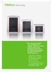
Universal Line free standing
• Provides unique features for system designers, installers and network managers.
• Suitable for office, equipment room and cabling closet installations
• Exceptionally rugged and strong
• Highly cost-effective and assembly-friendly solutions for numerous applications
• Multiple cable entry points provide maximum versatility
• Delivered as assembled and side by side mounting is possible
27
Universal Line free standing enclosures
Universal Line free standing enclosures
16U 20U22U 26U 32U
26U 36U
42U
36U
39U
42U
44U
47U
600 x 600
600 x 800
600 x 1000
47U
Universal Line JUMBO free standing enclosures
32U
42U
36U
39U
42U
44U
47U
800 x 600
800 x 1000
47U
Universal Line PCcase
36U
“
600 x 800
Highly cost-effective and
assembly-friendly solutions for
numerous applications.
28
”
800 x 800
UNIVERSAL LINE ENCLOSURES FOR
STANDARD DIMENSIONS:
Heights:16U, 20U, 22U, 26U 32U, 36U, 39U,
42U, 44U, 47U
Width: 600 mm
Depth: 600 mm - 800 mm
Heights: 26U, 36U, 42U, 47U
Width: 600 mm
Depth: 1000 mm
LOAD CARRYING CAPACITY: 600 kg
600x600 mm - 600x800 mm - 600x1000 mm
COLOUR:
RAL 9005 black
RAL 7035 light grey
STANDARDS:
ISO 9001: 2008 Quality Management Sytems
ISO 14001: 2004 Environmental Management System
19” mounting to IEC 297-1
EN 61587-1 mechanical structures (cabinets for electronic equipments)
Overall cabinet dimensions to IEC 297-2
KEY FEATURES
• The Universal Line free standing cabinets suitable for
office, equipment room, housing server and cabling closet
installations. Attention to styling with attractive colours
black RAL 9005 and light grey RAL 7035 with a smoked
glass door reinforced with vertical left and right metal
frames mean that cabinets can be deployed in the most
demanding of office environments when looks really
matter.
• However, Universal Line are an exceptionally rugged and
strong cabinet enabling it to be used for all application.
• Front door frames are available with decorative stripe as
orange.
• The Universal Line offers a highly cost-effective and
assembly-friendly solutions for numerous applications
in the field of network technology and electronics. The
Universal Line is highly configurable to the end users
requirements and provides unique features to benefit
system designers, installers and network managers.
• Standard cabinet is completely assembled. It is being
delivered as a single enclosure.
• Side by side mounting is also possible when side panels
are not used; baying kits to be added.
• The rigid welded frame construction can be
disassembled and assembled easily without any special
tools. Thus narrow doors, staircases and elevators are
no problem.
29
Universal Line free standing enclosures
Universal Line free standing enclosures
have a wide range of alternatives
30
UNIVERSAL LINE FREE STANDING ENCLOSURES FOR 600x600 mm - 600x800 mm - 600x1000 mm
EASY TO ACCESS
Front door
Features a full-length smoked and shatterproof glass
door with decorative accent stripe reinforced with
left/right metal frames and integral locking mechanism.
Side doors
Lockable, removable, complete with slam latches and
barrel type locks.
19” mounting angles (front/2ea and back/2ea) allow for
flexible configuration and adjustable in depth.
C rails 3 fold 1,5 mm thickness to increase the stability
of equipment .
Levelling feet is included as a standard feature.
Rear door
Lockable, removable with lock.
Secure, locking front and back doors with spring loaded
hinges offer best accessibility even when connecting the
cabinets. The door hinge is easily swapped from one
side to the other to change the door opening way.
All giving you 4-way access to equipment. Front and
rear door can be replaced that gives you flexibility for
different installations.
CABLE ACCESS
Multiple cable entry points provide maximum versatility.
There is a rubber edge sliding cover mechanism that
protects and fix the cables. There is a brush on the rear
panel that can be positioned on top or bottom (brush
entry available on height of 26 U and above)
CONSTRUCTION
Rigid welded frame construction in steel sheet, rapidly
disassembled with 4 screw per corner. Corner of bases
have welded sockets on each corner that tightly fixed
into the columns gives maximum stability.
Frames are made with 28-fold design for increased
stability.
Vented Pagoda style top cover with built-in space for
available top mount ventilation fan system providing
protection against dust flow from the top. Besides that
it cause a chimney effect to provide passive air flow via
convection.
31
Universal Line free standing
SELECTION STEPS FOR
600x600 mm - 600x800 mm
STEPS TO SELECT RIGHT FREE STANDING ENCLOSURE
In addition to Estap product part numbers, the options mentioned at the next page is to supply the right definition
to meet your requirements.
Each wall mounted and free standing enclosure section on the catalogue, has a ‘’Main part number structure’’ and
‘’Options’’ sections.
The below example explains how to select the right options for your needs.
The product part number has the below structure:
Product range name
+
U height (HHU)
+
Widht&Depth (WD)
+
Rear door option (RX)
The product options have the below structure:
Colour option (MX)
+
Front door option (FX)
HOW TO SELECT THE OPTIONS
Step 1
Please choose product part number.
For example: CKR42U66
Step 2
Please choose the colour from the table and place it after the part number.
For example: CKR42U66 - M02 (MX=Look at the MX colour options on the next page)
Step 3
Please choose the front door from the table and place it after MX colour.
For example: CKR42U66 - M02 - F01 (FX= look at the FX front door options on the next page)
Step 4
Please choose the rear door from the table and place it after FX front door option.
For example: CKR42U66 - M02 - F01 - R02 (RX= look at the RX rear door options on the next page)
32
PART NUMBER DEFINITION FOR
600x600 mm - 600x800 mm
FX
MAIN PART NUMBER STRUCTURE
CKR Product
range
Universal Line
F01*
Width
&
Depth
U
height
+
CKR
Front door options
- HHU - WD
+
HHU
F02
600
600
WD
16U
20U
22U
26U
CKR
32U
66
36U
68
H
H
39U
42U
44U
Front view
47U
Front view
F03
CKR: Universal Line free standing product range HHU: “U” height
WD: Width and depth
F04
600
600
OPTIONS
MX -
- RX**
Front door
options
Colour
options
MX
FX
+
FX
Rear door
options
+
H
H
RX
M01
F01*
R01
M02
F02
R02
F03
* F01 is the standard front door.
**RX - R01 is standard rear door for 22U and below, It is optional door for 26U and above
R02 is standard rear door for 26U and above with 2 brushed cable access part
Front view
RX**
Rear door options
300
R02
55
MX:
Colour options
M01= RAL 9005 black M02= RAL 7035 light grey
FX: Front door options
F01*= Single opening shatter proof glass door with left and right metal frame slotted, single point handled locking
F02= Single opening shatter proof glass door with complete metal frame slotted, single point handled locking
F03= Single opening solid metal door, single point handled locking
F04= Single opening %63 perforated door with complete metal frame slotted, single point handled locking
RX**: Rear door options
R01= Single opening solid metal rear door with barrel type single point lock unit for 22U and below
R02= Single opening solid metal rear door with barrel type single point lock unit with brushed cable entry, for 26U and above
Front view
R01
600
55
F04
H= Enclosure height
300
Back view
Back view
33
Universal Line free standing
TECHNICAL DRAWINGS FOR
600x600 mm - 16U/20U/22U
R01**
F01*
F02
F03
F04
Exploded view
Part
number
Product
definition
(mm)
U
Size
Width:
overall
(mm)
Depth:
overall
(mm)
Depth: max
mounting
profile (mm)
Height:
vertical
mounting
profile (mm)
Height:
without
levelling feet
(mm)
Height:
with
levelling feet
(mm)
Height:
with casters
(mm)
Universal Line free standing cabinets 19” 600 x 600 mm
CKR16U66
16U 600x600
16
600
600
390
715
865
880
945
CKR20U66
20U 600x600
20
600
600
390
890
1042
1057
1122
CKR22U66
22U 600x600
22
600
600
390
980
1131
1146
1211
* F01 is the standard front door.
** R01 is the standard rear door for 22U and below
34
TECHNICAL DRAWINGS FOR 600x600 mm - 16U/20U/22U
600
395
F01*
(Min 30)
111
300
(Min 520)
390
478
200
H
(Min 45)
95
Front view
Bottom view
600
19”
F02
Mounting profile
H
600
600
Front view
600
F03
H
Side view
Front view
H
Back view
Front view
600
600
600
F04
H
Top view
H= Enclosure height
Iso view
Front view
* F01is the standard front door.
35
Universal Line free standing
TECHNICAL DRAWINGS FOR
600x800 mm - 16U/20U/22U
R01**
F01*
F02
F03
F04
Exploded view
Part
number
Product
definition
(mm)
U
Size
Width:
overall
(mm)
Depth:
overall
(mm)
Depth: max
mounting
profile (mm)
Height:
vertical
mounting
profile (mm)
Height:
without
levelling feet
(mm)
Height:
with
levelling feet
(mm)
Height:
with casters
(mm)
Universal Line free standing cabinets 19” 600 x 800 mm
CKR16U68
16U 600x800
16
600
780
555
715
865
880
945
CKR20U68
20U 600x800
20
600
780
555
890
1042
1057
1122
CKR22U68
22U 600x800
22
600
780
555
980
1131
1146
1211
* F01 is the standard front door.
** R01 is the standard rear door for 22U and below
36
TECHNICAL DRAWINGS FOR
600x800 mm - 16U/20U/22U
600
F01*
395
200
(Min 30)
130
300
658
(Min 701)
555
H
(Min 45)
91
Front view
600
F02
19”
Bottom view
Mounting profile
H
600
780
Front view
H
600
F03
H
H
Front view
Side view
Back view
Front view
600
600
780
F04
H
Top view
H= Enclosure height
Iso view
Front view
* F01is the standard front door.
37
Universal Line free standing
TECHNICAL DRAWINGS FOR 600x600 mm - 26U/32U/36U/39U/42U/44U/47U
R02**
F01*
F02
F03
F04
Exploded view
Part
number
Product
definition
(mm)
U
Size
Width:
overall
(mm)
Depth:
overall
(mm)
Depth: max
mounting
profile (mm)
Height:
vertical
mounting
profile (mm)
Height:
without
levelling feet
(mm)
Height:
with
levelling feet
(mm)
Height:
with casters
(mm)
Universal Line free standing cabinets 19” 600 x 600 mm
CKR26U66
26U 600x600
26
600
600
390
1160
1309
1324
1389
CKR32U66
32U 600x600
32
600
600
390
1422
1576
1591
1656
CKR36U66
36U 600x600
36
600
600
390
1603
1754
1769
1834
CKR39U66
39U 600x600
39
600
600
390
1735
1887
1902
1967
CKR42U66
42U 600x600
42
600
600
390
1868
2021
2036
2101
CKR44U66
44U 600x600
44
600
600
390
1960
2110
2125
2190
CKR47U66
47U 600x600
47
600
600
390
2093
2244
2259
2324
* F01 is the standard front door.
** R02 is the standard rear door for 26U and above.
38
TECHNICAL DRAWINGS FOR 600x600 mm - 26U/32U/36U/39U/42U/44U/47U
600
F01*
395
H
(Min 520)
390
(Min 45)
95
478
200
(Min 30)
111
300
Bottom view
Front view
F02
600
19”
Mounting profile
600
300
55
600
H
Front view
600
F03
55
H
Front view
H
300
Back view
Side view
Front view
600
F04
600
600
H
Top view
H= Enclosure height
Iso view
Front view
* F01is the standard front door.
39
Universal Line free standing
TECHNICAL DRAWINGS FOR
600x800 mm - 26U/32U/36U/39U/42U/44U/47U
R02**
F01*
F02
F03
F04
Exploded view
Part
number
Product
definition
(mm)
U
Size
Width:
overall
(mm)
Depth:
overall
(mm)
Depth: max
mounting
profile (mm)
Height:
vertical
mounting
profile (mm)
Height:
without
levelling feet
(mm)
Height:
with
levelling feet
(mm)
Height:
with casters
(mm)
Universal Line free standing cabinets 19” 600 x 800 mm
CKR26U68
26U 600x800
26
600
780
555
1160
1309
1324
1389
CKR32U68
32U 600x800
32
600
780
555
1422
1576
1591
1656
CKR36U68
36U 600x800
36
600
780
555
1603
1754
1769
1834
CKR39U68
39U 600x800
39
600
780
555
1735
1887
1902
1967
CKR42U68
42U 600x800
42
600
780
555
1868
2021
2036
2101
CKR44U68
44U 600x800
44
600
780
555
1960
2110
2125
2190
CKR47U68
47U 600x800
47
600
780
555
2093
2244
2259
2324
* F01 is the standard front door.
** R02 is the standard rear door for 26U and above.
40
TECHNICAL DRAWINGS FOR 600x800 mm - 26U/32U/36U/39U/42U/44U/47U
395
600
F01*
200
(Min 30)
130
300
(Min 45)
91
658
(Min 701)
555
H
Bottom view
Front view
F02
600
19”
Mounting profile
780
300
55
600
H
Front view
600
F03
55
H
H
300
Front view
Side view
Back view
600
Front view
F04
780
600
H
Top view
H= Enclosure height
Iso view
Front view
* F01is the standard front door.
41
Universal Line free standing
SELECTION STEPS FOR 600x1000 mm
STEPS TO SELECT RIGHT FREE STANDING ENCLOSURE
In addition to Estap product part numbers, the options mentioned at the next page is to supply the right definition
to meet your requirements.
Each wall mounted and free standing enclosure section on the catalogue, has a ‘’Main part number structure’’ and
‘’Options’’ sections.
The below example explains how to select the right options for your needs.
The product part number has the below structure:
Product range name
+
U height (HHU)
+
Widht&Depth (WD)
+
Rear door option (RX)
The product options have the below structure:
Colour option (MX)
+
Front door option (FX)
HOW TO SELECT THE OPTIONS
Step 1
Please choose product part number.
For example: CKR42U6100
Step 2
Please choose the colour from the table and place it after the part number.
For example: CKR42U6100 - M02 (MX=Look at the MX colour options on the next page)
Step 3
Please choose the front door from the table and place it after MX colour.
For example: CKR42U6100 - M02 - F01 (FX= look at the FX front door options on the next page)
Step 4
Please choose the rear door from the table and place it after FX front door option.
For example: CKR42U6100 - M02 - F01 - R02 (RX= look at the RX rear door options on the next page)
42
PART NUMBER DEFINITION FOR 600x1000 mm
FX
MAIN PART NUMBER STRUCTURE
CKR Product
range Universal
Line
CKR
Front door options
- HHU - WD
+
HHU
F05*
Width
&
Depth
U
height
+
F06
600
600
WD
26U
6100
36U
CKR
42U
47U
H
CKR: Universal Line free standing product range HHU: U height
WD: Width and depth
H
Front view
Front view
F07
OPTIONS
F08
600
MX - FX - RX
Front
door
options
Colour
options
MX
+
FX
Rear
door
options
+
RX
M01
F05*
R01
M02
F06
R02*
F07
R03
F08
F04
MX:
Colour options
M01= RAL 9005 black M02= RAL 7035 light grey
FX: Front door options
F05*= Single opening shatter proof glass door with left and right metal frame slotted, single point handled locking F06= Single opening shatter proof glass door with complete metal frame slotted, single point handled locking
F07= Single opening solid metal door, single point handled locking
F08= Single opening %63 perforated door with complete metal frame slotted, single point handled locking
RX: Rear door options
R01= Single opening solid metal rear door with barrel type, single point lock unit R02*= Single opening solid metal rear door with barrel type, single point lock unit, brushed cable entry on top and bottom
R03= Double opening % 63 perforated rear door with complete frame, 3 point handled locking
F04= Single opening %63 perforated door with complete metal frame slotted, single point handled locking
H
H
Front view
Front view
RX
Rear door options
R02*
300
R03
R01
F04
55
600
Back view
Back view
Back view
Back view
H= Enclosure height
* F05 and R02 are the standart doors
43
Universal Line free standing
TECHNICAL DRAWINGS FOR 600x1000 mm - 26U/36U/42U/47U
R01
R03
F04
R02**
F05*
F06
F07
F08
Exploded view
U
Size
Width:
overall
(mm)
Depth:
overall
(mm)
Depth: max
mounting
profile (mm)
Height:
vertical
mounting
profile (mm)
Height:
without
levelling feet
(mm)
Height:
with
levelling feet
(mm)
Height:
with casters
(mm)
Universal Line free standing cabinets 19” 600 x 1000 mm
CKR26U6100 26U 600x1000
26
600
1000
740
1175
1309
1324
1389
CKR36U6100 36U 600x1000
36
600
1000
740
1620
1754
1769
1834
CKR42U6100 42U 600x1000
42
600
1000
740
1889
2021
2036
2101
CKR47U6100 47U 600x1000
47
600
1000
740
2110
2244
2259
2324
Part
number
Product
definition
(mm)
* F05 is the standard front door.
** R02 is the standard rear door for 26U and above.
44
TECHNICAL DRAWINGS FOR 600x1000 mm - 26U/36U/42U/47U
600
395
F05*
200
(Min 30)
150
300
878
(Min 921)
740
H
Front view
(Min 45)
106
Bottom view
1000
19”
Mounting profile
300
55
600
F06
600
H
Front view
600
F07
55
H
Front view
H
300
Back view
Side view
600
Front view
F08
1000
600
H
Top view
H= Enclosure height
Iso view
Front view
* F05 is the standard front door.
45
Universal Line free standing
TECHNICAL SPECIFICATIONS
TESTS AND CERTIFICATIONS
Environment EN61587-1 / 4.2, IEC60068-2, IEC60068-2-2, IEC60068-2-30, IEC60917 and IEC60297
Industrial environment
EN61587-1 / 4.3, IEC60068-2-42, IEC60068-2-43 and
IEC60068-2-49, IEC60068-2-I, IEC60917 and IEC60297
Statical mechanical structure load test EN61587-1 / 5.2.1, IEC60917 and IEC60297
Statical mechanical structure stability EN61587-1 / 5.2.2, IEC60917 and IEC60297
Dynamic load, vibration and mechanical stroke
EN61587-1 / 5.3.1, EN61587- / 5.3.3, IEC60917, C60297, IEC62208
Grounding continuity
EN61587-1 / 6.2, IEC60917 and IEC60297
Fire and flame resistance
EN61587-1 / 6.3, IEC60917 and IEC60297
Corrosion
ISO9227 and ASTM B 117-85, IEC60917 and IEC60297
IP protection degree
IP20 accordingly EN61587-1 / 6.4, IEC60529, IEC60917 and IEC60297
Transportation
ETS300019-1-2 Class2.3
Storage
ETS300019-1-1 Class1.2
Security
EN60950_LVD
PURCHASED PRODUCT CERTIFICATIONS
Sheet steel
DIN EN 10130 – 99 Ereğli DC-01 6112 , 7122, RoHS
Electrostatic powder coating
ISO 9001, ISO 2178, ISO 2813, ISO 6272, ISO 8130-5,
ISO 8130-3, RoHS
Fan
ISO 9001, CE (89/336/EEC EMC, 73/23/EEC LVD), RoHS
Glass
ISO 9001, EN 12150 – 1: 2000 tempered and secure
Fixings
DIN 7985, DIN 965, DIN 7981, DIN 934, DIN 985, DIN 933,
RoHS
Castors
TS EN 12530, TS EN 12532, RoHS
Lock
DIN 1743, DIN 53571, RoHS
46
KEY FEATURES
Main profile (framework) has a structure that would increase
mechanical resistance with aesthetic appearance, folded with an angle
of 45 degree and consist of 7 bending for each profile. Totally 28 fold
desing creates the framework stability. Tested to provide (x, y, z) axis
resistance that meets EN 61587-1/5.2.1 and 5.2.2 and external impact
resistance that meets EN 61587-1/5.3.3.
Bottom and upper case have a structure that would increase resistance
and strength of cabinet by mono-block bended, welded and profileinterlocking design. Profiles are manufactured to interlock bottom and
upper case with screws. Cable access at bottom case has a sliding type
blanking access plate that would block dust inlet.
A rubber edge on the cable access plate and thanks to its sliding
structure, it is capable of fixing the cables and allowing the cables to be
placed into cabinet without any damage.
Rear door is manufactured with 2 cable access part top/bottom with
brush for 26 U and above sizes*.
Rear door in standard configuration is single opening door which is
removable and lockable. For options please see the related drawings
and technical charts in pages 33-43-49-55.
Side panels have a structure that can be opened and removed with
slam latch and key. It is lockable and removable.
Front doors are with framed glass structure which is tempered,
anti-static, secure and smoked glass (4 mm thickness) with decorative
stripe, according to EN 12150-1:2000 standard. Front door in standard
configuration has left and right metal frame structure with high density
polyurethane adhesive and screw. For front door options please see the
related drawing and technical charts in pages 33-43-49-55.
Front door can be opened up to 135 degrees, removable and lockable with handle type locking unit.
Pagoda style vented top panel with a dedicated space of ventilation fan
module system allows easy installation of max. 4 fans.
19”(inch) mounting angles (2ea. in front and 2ea. in rear) are part of
cabinet interior configuration and adjustable in depth.
Baying is possible for side by side applications. Levelling feet is standard
in shipping configuration. The cabinet meets EN 61587-1, IEC 60917,
IEC 60297 standards, RoHS compliancy, Gost and TSE certified.
Cabinets are manufactured in our factory which has ISO 9001: 2008
Quality Assurance System and our responsibility for environment with ISO 14001:2004 Environmental Management System.
* Please see related drawings to define the difference of rear door design
between up to 26U and above 26U
TECHNICAL SPECIFICATIONS
Custom number
85380000 / 85381000 / 853710990019
Shipping structure
Assembled
Mounting type
Stand alone
Load carrying capacity (kg)
600
Certification on product
TSE, Gost
Surface finish
Electrostatic powder coated c/with surface treatment , 80 +/ - 5
micron paint thickness and tested according to IEC 60068-21,2-2, 2-30,2-42, 2-43, 2-49, 2-11
STANDARD PRODUCT
Standard colour
RAL 7035, RAL 9005
Standard stripe colour
Orange
IP protection standard
IP20
FRONT DOOR
Shatterproof glass with left and right metal frame
Glass
4 mm full-lenght smoked, shatterproof, tempered, secure
Front door construction
Single door opening with handled lock
Front door lock
Handle type, single point locking
Adhesive material
High density polyurethane DIN 53479, DIN 53505
Hinge system
Spring loaded
Door opening angle and swapping
135 degree, possible to swap one side to the other
SIDE PANEL
Solid metal, 1,2 mm left and right (2ea.)
Side panel construction
Lockable, removable c/with slam latches and lock
Side panel lock
Barrel type lock unit, single point + Slam latch (2ea)
REAR DOOR
Solid metal, 1,2 mm
Rear door construction
Single opening, solid metal with brushed cable entry on top and
bottom. Rear door lock
Barrel type lock unit, single point
Hinge system
Spring loaded
Door opening angle and swapping
135 degree, possible to swap one side to the other
TOP COVER
Solid metal 1,5 mm
Top cover construction
Pagoda type struction provides efficient air removal FRAMEWORK Top and bottom base units
Solid metal 1,5 mm
Top and bottom base units construction
Completely welded corner socket system
Uprights
Solid metal, 1,5 mm
Uprights construction
Tightly fixed into top and bottom base units 7 times folded INTERIOR PARTS 19’’ mounting angles
Solid metal, 1,5 mm
3 times folded 60x600, 600x800 / 1 time folded for 600x1000
“U” marking available 2ea. at rear, 2ea. at front
Pre-configured as 19’’ (482,6mm)
Free space to front door approx. 90 to 100 mm depends on
depth versions.
Zinc plated, passivated, 8-12 micron.
Adjustable in depth
C type support rails in depth
Solid metal, 1,5 mm 3 times folded, 2 ea. at left , 2 ea. at right up to 26U
3 ea. at left , 3 ea. at right 26U and higher
OPTIONS For the front and rear door options, please look at pages
33-43-49-55.
For the CUSTOMIZED PRODUCTS rather
than above options, please contact with sales
department. 47
Universal Line JUMBO
free standing
SELECTION STEPS FOR 800x800 mm
STEPS TO SELECT RIGHT FREE STANDING ENCLOSURE
In addition to Estap product part numbers, the options mentioned at the next page is to supply the right definition
to meet your requirements.
Each wall mounted and free standing enclosure section on the catalogue, has a ‘’Main part number structure’’ and
‘’Options’’ sections.
The below example explains how to select the right options for your needs.
The product part number has the below structure:
Product range name
+
U height (HHU)
+
Widht&Depth (WD)
+
Rear door option (RX)
The product options have the below structure:
Colour option (MX)
+
Front door option (FX)
HOW TO SELECT THE OPTIONS
Step 1
Please choose product part number.
For example: CKR42U88
Step 2
Please choose the colour from the table and place it after the part number.
For example: CKR42U88 - M02 (MX=Look at the MX colour options on the next page)
Step 3
Please choose the front door from the table and place it after MX colour.
For example: CKR42U88 - M02 - F09 (FX= look at the FX front door options on the next page)
Step 4
Please choose the rear door from the table and place it after FX front door option.
For example: CKR42U88 - M02 - F09 - R06 (RX= look at the RX rear door options on the next page)
48
PART NUMBER DEFINITION FOR 800x600 - 800x800 mm
FX
MAIN PART NUMBER STRUCTURE
CKR - HHU - WD
Product
range Universal
Line
CKR
Width
&
Depth
U
height
+
CKR
HHU
Front door options
+
F09*
WD
32U
86
36U
88
F10
780
780
39U
H
H
42U
44U
47U
CKR: Universal Line free standing product range HHU: “U” height
WD: Width and depth
Front view
F11
Front view
F12***
780
R04**
780
780
OPTIONS
MX - FX - RX
Front
door
options
Colour
options
MX
+
FX
Rear
door
options
+
H
H
RX
M01
F09*
R04**
M02
F10
R05
F11
R06*
F12***
F12***
Front view
Front view
Rear door options
R04**
R06*
55
300
H
55
MX:Colour options
M01= RAL 9005 black M02= RAL 7035 light grey
FX: Front door options
F09*= Double opening shatter proof glass door with left and right metal frame slotted, two point barrel type locking
F10= Single opening shatter proof glass door with complete metal frame slotted, single point handled locking
F11= Single opening solid metal door, single point handled locking
F12***= Single opening %63 perforated door with complete metal frame slotted, single point handled locking
R04**= Double opening %63 perfore door with complete metal frame, 3 point handled locking RX:Rear door options
R06*= Double opening complete metal door with brushed cable entry, barrel type single point lock unit.
R04**= Double opening %63 perforated door with complete metal frame, 3 point handled locking
R05= Single opening solid metal rear door with barrel type, single point lock unit
F12***= Single opening %63 perforated door with complete metal frame slotted, single point handled locking
Front view
RX
R04**
* F09 and R06 are the standart doors
** R04 can be usable as front door as well.
*** F12 can be usable as rear door as well.
H
300
Back view
R05
Back view
Back view
F12***
Back view
H= Enclosure height
49
Universal Line JUMBO
TECHNICAL DRAWINGS FOR
800x600 mm - 32U/36U/39U/42U/44U/47U
F12***
R05
R04**
R06*
F09*
F10
F11
R04**
F12***
Exploded view
Part
number
Product
definition
(mm)
U
Size
Width:
overall
(mm)
Depth:
overall
(mm)
Depth: max
mounting
profile (mm)
Height:
vertical
mounting
profile (mm)
Height:
without
levelling feet
(mm)
Height:
with
levelling feet
(mm)
Height:
with casters
(mm)
Universal Line JUMBO cabinets 19” 800 x 600 mm
CKR32U86
32U 800x600
32
780
600
365
1422
1576
1591
1656
CKR36U86
36U 800x600
36
780
600
365
1603
1754
1769
1834
CKR39U86
39U 800x600
39
780
600
365
1735
1887
1902
1967
CKR42U86
42U 800x600
42
780
600
365
1868
2021
2036
2101
CKR44U86
44U 800x600
44
780
600
365
1960
2110
2125
2190
CKR47U86
47U 800x600
47
780
600
365
2093
2244
2259
2324
* F09 and R06 are the standard doors.
** R04 can be usable as front door as well.
*** F12 can be usable as rear door as well.
50
TECHNICAL DRAWINGS FOR 800x600 mm - 32U/36U/39U/42U/44U/47U
F09*
515
F10
780
300
478
(Min 408)
365
55
H
(Min 138)
141
200
780
(Min 50)
90
300
19”
Bottom view
Front view
Mounting profile
780
Front view
F11
780
300
55
600
H
H
H
H
Front view
F12
55
780
Front view
300
Side view
H
Back view
Front view
780
R04
55
300
600
780
H
Top view
H= Enclosure height
Iso view
Front view
* F09 is the standart door.
51
Universal Line JUMBO
TECHNICAL DRAWINGS
800x800 mm - 32U/36U/39U/42U/44U/47U
F12***
R05
R04**
R06*
F09*
F10
F11
R04**
F12***
Exploded view
Part
number
Product
definition
(mm)
U
Size
Width:
overall
(mm)
Depth:
overall
(mm)
Depth: max
mounting
profile (mm)
Height:
vertical
mounting
profile (mm)
Height:
without
levelling feet
(mm)
Height:
with
levelling feet
(mm)
Height:
with casters
(mm)
Universal Line JUMBO cabinets 19” 800 x 800 mm
CKR32U88
32U 800x800
32
780
780
550
1422
1576
1591
1656
CKR36U88
36U 800x800
36
780
780
550
1603
1754
1769
1834
CKR39U88
39U 800x800
39
780
780
550
1735
1887
1902
1967
CKR42U88
42U 800x800
42
780
780
550
1868
2021
2036
2101
CKR44U88
44U 800x800
44
780
780
550
1960
2110
2125
2190
CKR47U88
47U 800x800
47
780
780
550
2093
2244
2259
2324
* F09 and R06 are the standard doors.
** R04 can be usable as front door as well.
*** F12 can be usable as rear door as well.
52
TECHNICAL DRAWINGS FOR 800x800 mm - 42U/47U
515
300
(Min 40)
95
F10
780
(Min 720)
550
780
H
H
(Min 130)
131
658
300
85
300
F09*
Front view
19”
Bottom view
Mounting profile
Front view
F11
780
780
300
55
780
H
H
H
Front view
F12
55
780
Front view
300
Side view
Back view
H
780
Front view
R04
55
780
300
780
H
Top view
H= Enclosure height
Iso view
Front view
* F09 is the standard front door.
53
Universal Line JUMBO free standing
SELECTION STEPS FOR 800x1000 mm
STEPS TO SELECT RIGHT FREE STANDING ENCLOSURE
In addition to Estap product part numbers, the options mentioned at the next page is to supply the right definition
to meet your requirements.
Each wall mounted and free standing enclosure section on the catalogue, has a ‘’Main part number structure’’ and
‘’Options’’ sections.
The below example explains how to select the right options for your needs.
The product part number has the below structure:
Product range name
+
U height (HHU)
+
Widht&Depth (WD)
+
Rear door option (RX)
The product options have the below structure:
Colour option (MX)
+
Front door option (FX)
HOW TO SELECT THE OPTIONS
Step 1
Please choose product part number.
For example: CKR42U8100
Step 2
Please choose the colour from the table and place it after the part number.
For example: CKR42U8100 - M02 (MX=Look at the MX colour options on the next page)
Step 3
Please choose the front door from the table and place it after MX colour.
For example: CKR42U8100 - M02 - F09 (FX= look at the FX front door options on the next page)
Step 4
Please choose the rear door from the table and place it after FX front door option.
For example: CKR42U8100 - M02 - F09 - R06 (RX= look at the RX rear door options on the next page)
54
PART NUMBER DEFINITION FOR 800x1000 mm
FX
MAIN PART NUMBER STRUCTURE
CKR - HHU - WD
Product
range Universal
Line
CKR
Front door options
Width
&
Depth
U
height
+
HHU
+
WD
H
H
Front view
F11
Front view
F12***
780
R04**
780
780
MX - FX - RX
Front
door
options
Colour
options
MX
+
FX
Rear
door
options
+
H
RX
M01
F09*
R04**
M02
F10
R05
F11
R06*
F12
F12***
H
Front view
Front view
Front view
R04**
RX
MX:Colour options
M01= RAL 9005 black M02= RAL 7035 light grey
FX: Front door options
F09*= Double opening shatter proof glass door with left and right metal frame slotted, two point barrel type locking
F10= Single opening shatter proof glass door with complete metal frame slotted, single point handled locking
F11= Single opening solid metal door, single point handled locking
F12***= Single opening %63 perforated door with complete metal frame slotted, single point handled locking
R04**= Double opening %63 perforated door with complete metal frame, 3 point handled locking RX:Rear door options
R05= Single opening solid metal rear door with barrel type, single point lock unit
R04**= Double opening %63 perforated door with complete metal frame, 3 point handled locking
R06*= Double opening complete metal door with brushed cable entry, barrel type single point lock unit.
F12***= Single opening %63 perforated door with complete metal frame slotted, single point handled locking
Rear door options
* F09 and R06 are the standart doors
** R04 can be usable as front door as well.
*** F12 can be usable as rear door as well.
R04**
R06*
55
300
H
55
780
47U
CKR: Universal Line product range HHU: “U” height
WD: Width and depth
OPTIONS
F10
780
8100
42U
CKR
F09*
300
Back view
R05
Back view
Back view
F12***
Back view
H= Enclosure height
55
Universal Line JUMBO
TECHNICAL DRAWINGS FOR
800x1000 mm - 42U/47U
F12***
R05
R04**
R06*
F09*
F10
F11
R04**
F12***
Exploded view
Part
number
Product
definition
(mm)
U
Size
Width:
overall
(mm)
Depth:
overall
(mm)
Depth: max
mounting
profile (mm)
Height:
vertical
mounting
profile (mm)
Height:
without
levelling feet
(mm)
Height:
with
levelling feet
(mm)
Height:
with casters
(mm)
Universal Line JUMBO cabinets 19” 800 x 1000 mm
CKR42U8100
42U 800X1000
42
780
1000
740
1889
2021
2036
2101
CKR47U8100
47U 800X1000
47
780
1000
740
2110
2244
2259
2324
* F09 and R06 are the standard doors.
** R04 can be usable as front door as well.
*** F12 can be usable as rear door as well.
56
TECHNICAL DRAWINGS FOR 800x1000 mm - 42U/47U
515
300
(Min 26)
120
F10
780
780
(Min 852)
740
(Min 118)
136
878
300
85
300
F09*
Bottom view
H
H
Front view
19”
Mounting profile
Front view
F11
780
780
1000
55
300
H
H
H
Front view
55
F12
Front view
780
300
Side view
Back view
H
780
Front view
R04
780
1000
300
55
H
Top view
H= Enclosure height
Iso view
Front view
* F09 is the standard front door.
57
Universal Line JUMBO
TECHNICAL SPECIFICATIONS
TESTS AND CERTIFICATIONS
Environment EN61587-1 / 4.2, IEC60068-2, IEC60068-2-2, IEC60068-2-30, IEC60917 and IEC60297
Industrial environment
EN61587-1 / 4.3, IEC60068-2-42, IEC60068-2-43 and
IEC60068-2-49, IEC60068-2-I, IEC60917 and IEC60297
Statical mechanical structure load test EN61587-1 / 5.2.1, IEC60917 and IEC60297
Statical mechanical structure stability EN61587-1 / 5.2.2, IEC60917 and IEC60297
Dynamic load, vibration and mechanical stroke
EN61587-1 / 5.3.1, EN61587- / 5.3.3, IEC60917, C60297, IEC62208
Grounding continuity
EN61587-1 / 6.2, IEC60917 and IEC60297
Fire and flame resistance
EN61587-1 / 6.3, IEC60917 and IEC60297
Corrosion
ISO9227 and ASTM B 117-85, IEC60917 and IEC60297
IP protection degree
IP20 accordingly EN61587-1 / 6.4, IEC60529, IEC60917 and IEC60297
Transportation
ETS300019-1-2 Class2.3
Storage
ETS300019-1-1 Class1.2
Security
EN60950_LVD
PURCHASED PRODUCT CERTIFICATIONS
Sheet steel
DIN EN 10130 – 99 Ereğli DC-01 6112 , 7122, RoHS
Electrostatic powder coating
ISO 9001, ISO 2178, ISO 2813, ISO 6272, ISO 8130-5,
ISO 8130-3, RoHS
Fan
ISO 9001, CE (89/336/EEC EMC, 73/23/EEC LVD), RoHS
Glass
ISO 9001, EN 12150 – 1: 2000 tempered and secure
Fixings
DIN 7985, DIN 965, DIN 7981, DIN 934, DIN 985, DIN 933,
RoHS
Castors
TS EN 12530, TS EN 12532, RoHS
Lock
DIN 1743, DIN 53571, RoHS
58
KEY FEATURES
Main profile (framework) has a structure that would increase
mechanical resistance with aesthetic appearance, folded with an angle
of 45 degree and consist of 7 bended surfaces for each profile.Totally
28 fold design creates the framework stability.Tested to provide (x, y, z)
axis resistance that meets EN 61587-1 / 5.2.1 and 5.2.2, and external
impact resistance that meets EN 61587-1 / 5.3.3.
Bottom and upper case have a structure that would increase resistance
and strength of cabinet by mono block bended, welded and
profile-interlocking design. Profiles are manufactured to interlock
bottom and upper case with screws. Cable access at bottom case has a
sliding type blanking access plate that would block dust inlet.
A rubber edge on the cable access plate and thanks to its sliding
structure, it is capable of fixing the cables and allowing the cables to be
placed into cabinet without any damage. Additionally both on top and
bottom, there are brushed cable entry plates for mass cabling needs.
Rear door is manufactured with 2 cable access part top/bottom with
brush.
Rear door in standard configuration is double opening door which is
removable and lockable. For options please see the related drawing and
technical charts in pages 33-43-49-55.
Side panels have a structure that can be opened and removed with
slam latch and key. It is lockable and removable.
Front doors are with framed glass structure which is tempered,
anti-static, secure and smoked glass (4 mm thickness) with decorative
stripe, according to EN 12150-1:2000 standard. Front door in standard
configuration has left and right metal frame structure with high density
polyurethane adhesive and screw and double openning.
For options please see the related drawing and technical charts
in pages 33-43-49-55.
Front door is double openning door which can be opened up to 135
degrees, removable and lockable with handle type locking unit.
Pagoda style vented top panel with a dedicated space of ventilation fan
module system allows easy installation of max. 4 fans.
19”(inch) mounting angles (2ea. in front and 2ea. in rear) are part of
cabinet interior configuration and adjustable in depth.
Baying is possible for side by side applications. Levelling feet is standard
in shipping configuration.The cabinet meets EN 61587-1, IEC 60917,
IEC 60297 standards, RoHS compliancy, Gost and TSE certified.
Cabinets are manufactured in our factory which has ISO 9001: 2008
Quality Assurance System and our responsibility for enviroment with ISO 14001: 2004 Environmental Management System.
TECHNICAL SPECIFICATIONS
Custom number
85380000 / 85381000 / 853710990019
Shipping structure
Assembled
Mounting type
Stand alone
Load carrying capacity (kg)
600
Certification on product
TSE, Gost
Surface finish
Electrostatic powder coated c/with surface treatment , 80 +/ - 5
micron paint thickness and tested according to IEC 60068-21,2-2, 2-30,2-42, 2-43, 2-49, 2-11
STANDARD PRODUCT
Standard colour
RAL 7035, RAL 9005
Standard stripe colour
Orange
Baying
Possible with baying kit for side by side applications without side
panels
IP protection standard
IP20
FRONT DOOR
Shatterproof glass with left and right metal frame
Glass
4 mm full-lenght smoked, shatterproof, tempered, secure
Front door construction
Double opening door with handled lock
Front door lock
Handle type, single point locking
Adhesive material
High density polyurethane DIN 53479, DIN 53505
Hinge system
Spring loaded
Door opening angle and swapping
135 degree
SIDE PANEL
Solid metal, 1,2 mm left and right (2ea.)
Side panel construction
Lockable, removable c/with slam latches and lock
Side panel lock
Barrel type lock unit, single point + Slam latch (2ea)
REAR DOOR
Solid metal, 1,2 mm
Rear door construction
Double door opening, lockable, removable Rear door lock
Barrel type lock unit, single point
Hinge system
Spring loaded
Door opening angle and swapping
135 degree
TOP COVER
Solid metal 1,2 mm
Top cover construction
Pagoda type, allow efficient air removal FRAMEWORK Top and bottom base units
Solid metal 1,5 mm
Top and bottom base units construction
Completely welded corner socket system
Uprights
Solid metal, 1,5 mm
Uprights construction
Tightly fixed into top and bottom base units 7 times folded INTERIOR PARTS 19’’ mounting angles
Solid metal, 1,5 mm
3 times folded 800x600, 800x800 / 1 time folded for 800x1000
“U” marking available
2ea. at rear, 2ea. at front
Pre-configured as 19’’ (482,6 mm)
Free space to front door approx. 90 to 100 mm depends on
depth versions.
Zinc plated, passivated, 8-12 micron.
Adjustable in depth
Omega type support rails in depth
Solid metal, 1,5 mm 3 times folded
2 ea. at left , 2 ea. at right up to 26U
3 ea. at left , 3 ea. at right 26U and higher
OPTIONS For the front and rear door options, please look at pages
33-43-49-55.
For the CUSTOMIZED PRODUCTS rather
than above options, please contact with sales
department. 59
Universal Line JUMBO
Accessories
SPECIAL ACCESSORIES* FOR JUMBO
Teleskopic cable trunking
It is designed to protect and hide cable bundles coming from
the ceiling. Since the height between ceiling and cabinet isn’t
known, it is manufactured as teleskopic to fit all dimensions.
There is cover for it. When it is closed, provides very
professional look.
Vertical cable management channels
(left and right)
It is designed to manage large patch cable bundles in front of
the cabinet. It is installed through the height of the cabinet,
and each “U” dimension, there is a hole to pass horizontal
patch cables on vertical axis.There is spring hinged cover in
front of the vertical cable management panel integral with
slam latch.The cover protect and hide all cable bundles. When it is closed, it looks really matter and provide
professional look. Besides that, it reduces labour cost
around %20 and save time.
Vertical cable management trunking
It is designed to carry large cable bundles through the
vertical axis of the cabinet. From top to bottom, it is
continuous with the height of cabinet. Bottom edge of the
trunking fit into the cabinet bottom cable entry, top edge of
the trunking fit into the cabinet top cable entry. It has holes
for cable access for horizantal axis. It is punched in a shape
to tie the cables. Since it has a sliding cover on the trunking,
cable bundles are hidden and protected. When it is closed, it
looks really matter and provide professional look.
*See accessories for product part numbers, definitions and contact with sales department.
Professional cabling solutions
with JUMBO
Left and right cable management panels
hide and protect all networking cables
that brings professional look after
integration.
Double openning rear doors provide space saving
between cabinet and wall.
60
UNIVERSAL LINE JUMBO FEATURES
Perforated, vented Pagoda-style top
providing maximum
protection against dust
Front door with
integrated locking
mechanism for added
security
integral locking
mechanism.
Side panel comes with
snap closures and locks
providing security while
four-way access to the
equipment is applicable.
Sliding access panel on
the bottom for cable
entry and a brush entry
on the rear panel that
can be positioned on the
top or bottom
61
Universal Line PCcase free standing
600x800 mm - 36U
STANDARD DIMENSIONS:
Height: 36U
Width: 600 mm
Depth: 800 mm
STANDARDS:
ISO 9001: 2008 Quality Management Sytems
ISO 14001: 2004 Environmental Management System
19” mounting to IEC 297-1
EN 61587-1 mechanical structures (cabinets for electronic equipments)
Overall cabinet dimensions to IEC 297-2
COLOUR:
RAL 9005 black
RAL 7035 light grey
• 19”
• FITS YOUR DECORATION AND ENVIRONMENT
• SECURE AND STURDY
• EASY TO MAINTENANCE AND HIGH INNER VOLUME
• DUST PROOF
• AIR CIRCULATION WITH VENTED FILTERS
62
PCcase is ideal for office, factory, workshop, storage,
store, gas stations and laboratories etc. as server
housing. It protects your servers and devices against
dust, humidity, hot/cold air but most important that
against unauthorized peoples. Servers, all kind of PC’s,
monitors, keyboards, UPS’s, switches and networking
products can easily be placed in it.
Its ergonomy provides the keyboards are in hands level
and monitor is at eye level.
600x800 mm - 36U
FEATURES
PCCcase cabinets match all features defined for
Universal Line as main construction.
It has 3 sections;
1st compartment: Screen section
11U space covered, not 19’’, equipped with a fixed
shelf which should be base for the screen unit).
2nd Compartment: Keyboard section
3U space covered (not 19’’, equipped with a specific
sliding shelf integrated with mouse housing and
platform).
3rd Compartment: Device section
19” 22U usable (19’’, 22U rail that is possible to use
all standart accessories to mount all kind of devices
printers, UPS, server or any LAN/WAN devices...)
All compartments are lockable.
Both side doors are lockable, removable, and
openable.
Side doors have filtered and vented air circulation
trays that allow air circulation or air entry.
It is possible to use together with cooling fans and
also have filtered and vented tray on top that allow
air circulation.
Bottom section have two door options:
Glass door or solid metal door.
63
Universal Line PCcase
TECHNICAL DRAWINGS
600x800 mm - 36U
Exploded view
64
Height:
with
levelling feet
(mm)
Height:
with casters
(mm)
36U 600x800 mm PCcase, metal door
section at bottom
Height:
without
levelling feet
(mm)
PCCASE36M
Height:
vertical
mounting
profile (mm)
36U 600x800 mm PCcase, glass door
section at bottom
Depth: max
mounting
profile (mm)
PCCASE36
Depth:
overall
(mm)
Product
definition
(mm)
Width:
overall
(mm)
Part
number
U
Size
Universal Line PCcase cabinets 19” 600 x 800 mm
36
600
780
555
1603
1744
1759
1824
TECHNICAL DRAWINGS FOR 600x800 mm - 36U
395
600
(Min 30)
91
1746
(Min 701)
555
658
200
(Min 30)
130
300
19”
Bottom view
Mounting profile
600
780
1746
Front view with glass door
600
Front view
Side view
Back view
1746
600
780
302
350
Front view with metal door
Top view
Iso view
65
Universal Line
free standing accessories
FREQUENTLY USED ACCESSORIES SELECTION TABLE FOR Universal Line
Estap has a wide range of accessories: Fixed shelves, heavy duty fixed shelves, sliding shelves, fans, cooling units,
vertical cable managements, cable rings, organisers, trays, plinth and so on...
* See the other accessories and part number definitions at the pages 173-213.
* Please mention colour choice in your orders. M01=RAL 9005 black and M02= RAL 7035 light grey
Frequently used accessories selection table
Universal Line /
Shelves
part numbers
Fixed shelves
Enclosure Sizes (mm)
PCcase
-
600x1000
-
-
800x600
M55SR720
M44HRK80 M44HRK60 M44HRK80
Heavy duty sliding shelves
800x800
800x1000
-
-
-
-
-
-
M44HRK60 M44HRK80
M55HR720
M55SR720
-
-
-
M55HR720
Universal Line /
Fan units
part numbers
PCcase
600x600
600x800
600x1000
800x600
800x800
800x1000
2 Fan unit with on/off switch
M44HV2F
M44HV2F
M44HV2F
M44HV2F
M44HV2F
M44HV2F
M44HV2F
4 Fan unit with on/off switch
M44HV4F
M44HV4F
M44HV4F
M44HV4F
M44HV4F
M44HV4F
M44HV4F
2 Fan unit with thermostat unit
M44HV2FT M44HV2FT M44HV2FT M44HV2FT M44HV2FT M44HV2FT
M44HV2FT
4 Fan unit with thermostat unit
M44HV4FT M44HV4FT M44HV4FT M44HV4FT M44HV4FT M44HV4FT
M44HV4FT
Universal Line /
Cable management
part numbers
1U cable management
panel (5 rings)
Vertical cable management
Universal Line /
PDU
part numbers
Enclosure Sizes (mm)
Enclosure Sizes (mm)
PCcase
600x600
600x800
600x1000
800x600
E44ORG1U E44ORG1U E44ORG1U E44ORG1U E44ORG1U
-
-
-
-
800x800
800x1000
E44ORG1U
E44ORG1U
M44ORGxxU M44ORGxxU M44ORGxxU
Enclosure Sizes (mm)
PCcase
600x600
600x800
600x1000
800x600
800x800
800x1000
6 way PDU with 1x16A
CCT breaker,1U
M446AL
M446AL
M446AL
M446AL
M446AL
M446AL
M446AL
9 way PDU with 1x16A
CCTbreaker, 2U
M449ALC
M449ALC
M449ALC
M449ALC
M449ALC
M449ALC
M449ALC
800x600
800x800
800x1000
Universal Line /
Castor
part numbers
Castor group
Fixings/ cagenut, screw, washer
(1set=20 pcs.)
66
600x800
M44SBR80 M44SBR60 M44SBR80 M44SBR100 M44SBR60 M44SBR80 M44SBR100
Heavy duty fixed shelves
Sliding shelves
600x600
Enclosure Sizes (mm)
PCcase
600x600
600x800
600x1000
M22TKGR1 M22TKGR1 M22TKGR1 M22TKGR1 M22TKGR1 M22TKGR1
KFS6X15
KFS6X15
KFS6X15
KFS6X15
KFS6X15
KFS6X15
M22TKGR1
KFS6X15