1
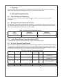
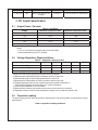
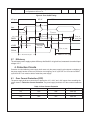
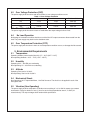
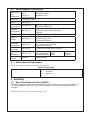
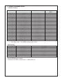
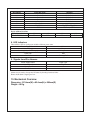
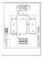
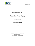
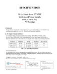
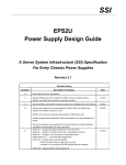
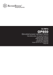
IS-600S2UPD8
IS -600S2UPD8
Redundant Power Supply
( 2U- 600W 8 0 P L U S )
SPECIFICATION
Revision: 1.0
727
, . Phillips Drive City of Industry. CA 91748. USA
http:// www.Xeal.com
TEL: 626-3038885
FAX: 626-3010588
1. Purpose
This specification defines the performance characteristics and functions of a 600 watts 2U form factor of
switch mode redundant power supply with Active PFC (Power Factor Correction).
2. AC Input Requirements
2.1
Input Voltage and Frequency
Voltage (sinusoidal) : 100~240 VAC full range, with 10% tolerance. Input frequency ranges from
47hz~63hz
2.2
AC Input Current and Inrush Current
AC line inrush current shall not damage any component nor cause the AC line fuse to blow under any
DC conditions and with any specified AC line input voltage and frequency. Repetitive On/Off cycling of
the AC input voltage shall not damage the power supply.
Table 1: AC Input Current and Inrush Current
2.3
Input
Voltage
Maximum
Input Current
Maximum
Inrush Current
100~240VAC
10A~5A
60Apeak@115VAC
Input Power Factor Correction (Active PFC)
The power factor at 100% of rated load shall be ≥ 0.97 at nominal input voltage.
2.4
AC Line Transient Specification
AC line transient conditions are characterized as “sag” and “surge” conditions. Sag conditions (also referred
to as “brownout” conditions) will be defined as the AC line voltage dropping below nominal voltage. Surge
conditions will be defined as the AC line voltage rising above nominal voltage. The power supply shall meet
the regulation requirements under the following AC line sage and surge conditions.
Table 2: AC Line Sag Transient Performance
Duration
Sag
Operating AC Voltage
Line
Frequency
Load
Performance Criteria
Continuous
10%
Nominal AC Input ranges
50/60 Hz
100%
No loss of function or
performance
0-1 AC cycle
100%
Nominal AC Input ranges
50/60 Hz
80%
No loss of function or
performance
> 1 AC cycle
> 10%
Nominal AC Input ranges
50/60 Hz
100%
Loss of function Acceptable,
Self- recoverable
Table 3: AC Line Surge Transient Performance
Duration
Surge
Operating AC Voltage
Line Frequency
Performance Criteria
Continuous
10%
Nominal AC Voltage
50/60 Hz
No loss of function or performance
0 - ½ AC cycle
30%
Mid-point of Nominal AC
Voltage
50/60 Hz
No loss of function or performance
3. DC Output Specification
3.1
Output Power / Currents
Voltage
Table 4: Load Range
Minimum Continuous Load
Maximum Continuous Load1,3
+3.3V
0.5A
25A
+5V
0.5A
25A
+12V
0.8A
48A
-12V
0.1A
0.5A
+5VSB
0.1A
3.5A
Notes:
1: The +3.3 &+5 Volt total outputs shall not exceed 150W.
2: Noise bandwidth is from DC to 20 MHz
3.2
Voltage Regulation, Ripple and Noise
Output Voltage
Table 5: Regulation, ripple and noise
+3.3V
+5V
+12V
-12V
+5VSB
Load Reg.
±5%
±5%
±5%
±5%
±5%
Line Reg.
±1%
±1%
±1%
±1%
±1%
Ripple & Noise
60mV
60mV
120mV
120mV
60mV
Ripple and noise shall be measured using the following methods:
a) Measurements made differentially to eliminate common-mode noise
b) Ground lead length of oscilloscope probe shall be ≤ 0.25 inch.
c) Measurements made where the cable connectors attach to the load.
d) Outputs bypassed at the point of measurement with a parallel combination of
10uF tantalum capacitor in parallel with 0.1uF ceramic capacitors.
e) Oscilloscope bandwidth of 0 Hz to 20MHz.
f) Measurements measured at locations where remote sense wires are connected.
g) Regulation tolerance shall include temperature change, warm up drift and dynamic load
3.3
Capacitive Loading
The power supply shall be stable and meet all requirements in the following table, except dynamic loading
requirements.
Table 6: Capacitive Loading Conditions
3.4
Output
MIN
MAX
Units
+3.3V
10
12,000
uF
+5V
10
12,000
uF
+12V
10
11,000
uF
-12V
1
350
uF
+5VSB
1
350
uF
Dynamic Loading
The output voltages shall remain within the limits specified in Table-Regulation, ripple and noise for the
step loading and within the limits specified in Table-Transient Load Requirement for the capacitive loading.
The load transient repetition rate shall be tested between 50Hz and 5kHz at duty cycle ranging from
10%-90%. The load transient repetition rate is only a test specification. The step load may occur
anywhere within the MIN load to the MAX load shown in Table-Load Range.
Table 7: Transient Load Requirements
Step Load Size
Load Slew Rate
Output
3.5
Capacitive Load
+5V
30% of Max. Load
0.5 A/uS
1000 uF
+3.3V
30% of Max. Load
0.5 A/uS
1000 uF
+12V
50% of Max. Load
0.5 A/uS
2200 uF
+5VSB
30% of Max. Load
0.5 A/uS
1 uF
Overshoot at Turn-on/Turn-off
Any output overshoot at turn on shall be less than 10% of the nominal output value. Any overshoot shall
recover to be within regulation requirements in less than 10ms.
3.6
Timing Requirements
Table 8: Output Voltage Timing
MIN
MAX
Units
Output voltage rise time from each main output
1
30
mS
Output voltage rise time for the 5Vsb out put
1
25
mS
Item
Description
Tvout_rise
Tvout_on
All main output must be within regulation of each other
within
this time.
50
mS
Tvout_off
All main output must leave regulation within this time
400
mS
Figure 1: Output Voltage Timing
Vout
V1
10% Vout
V2
V3
V4
Tvout_on
Tvout_off
Tvout_rise
Table 9: Turn On/Off Timing
Item
Description
MIN
MAX
Units
Tsb_on-delay
Delay from AC being applied to +5VSB being within
regulation.
1500
mS
Tac_on-delay
Delay from AC being applied to all output voltages
being
within regulation.
2500
mS
Tvout_holdup
Time all output voltage stay within regulation after loss
of AC tested at 80% of maximum load.
17
mS
Tpwok_holdup
Delay from loss of AC deassertion of PWOK tested at
80% of maximum load.
16
mS
Tpson_on_delay
Delay from PSON# active to output voltage within
regulation limits.
5
Tpson_pwok
Delay from PSON# deactive to PWOK being
deasserted.
Tpwok_on
Delay from output voltage within regulation limits to
PWOK asserted at turn on.
100
Tpwok_off
Delay from PWOK deasserted to output voltages
(+5V, +3.3V, +12V, -12V) dropping out of regulation
limits.
1
mS
Tpwok_low
Duration of PWOK being in the deasserted state
during an off/on cycle using AC or the PSON#
signal. .
100
mS
400
mS
50
mS
1000
mS
Tsb_vout
Delay from +5VSB being in regulation to O/Ps being
in regulation at AC turn on.
50
1000
mS
Figure 2: Turn On/Off Timing
AC Input
AC off
AC On
Tvout_holdup
Vout
Tac_on-delay
Tpwok_low
Tsb_on-delay
PWOK
Tpwok_on
+5VSB
Tsb_vout
Tpwok_off
Tpwok_holdup
Tpwok_off
Tsb_on-delay
Tpwok_on
Tpson_pwok
Tsb_holdup
Min.>70mS
Tpson_on_delay
PSON#
AC turn 0n/off cycle
3.7
PSON turn on/off cycle
Efficiency
The minimum power supply system efficiency shall be 80% at typical load, measured at nominal input
voltage 115 V
4. Protection Circuits
Protection circuits inside the power supply shall cause only the power supply’s main outputs to shutdown. If
the power supply latches off due to a protection circuit tripping, an AC cycle OFF for 15 sec and a PSON#
cycle HIGH for 1 sec must be able to restart the power supply.
4.1
Over Current Protection (OCP)
The power supply shall have current limit to prevent the +5V, +3.3V, and +12V outputs from exceeding the
values shown in Table-Over Current Protection. The power supply shall latch off if the current exceeds the
limit.
Voltage
Table 10: Over Current Protection
Minimum
Maximum
Shutdown Mode
+5V
27A
38A
Latch Off
+3.3V
27A
38A
Latch Off
+12V
53A
72A
Latch Off
4.2
Over Voltage Protection (OVP)
The power supply shall shut down and latch off after an over voltage conditions occurs.
Table 11: Over Voltage Protection
Voltage
Minimum
Maximum
Shutdown Mode
4.3
+5V
+5.7V
+6.5V
Latch Off
+3.3V
+3.9V
+4.5V
Latch Off
+12V
+13.3V
+14.5V
Latch Off
Short Circuit Protection
The power supply shall shut down in latch off mode when the output voltage is short circuit.
4.4
No Load Operation
No damage or hazardous condition should occur with all the DC output connectors disconnected from the
load. The power supply may latch into the shutdown state.
4.5
Over Temperature Protection (OTP)
The power supply will shut down i when an over temperature condition occurs; no damage shall be caused.
5. Environmental Requirements
5.1
Temperature
Operating Ambient, normal mode (inlet air): 0°C ~ 50°C (32°F~ 113°F)
Non-operating Ambient:: -40°C ~ 70°C (-40°F~ 158°F)
5.2
Humidity
Operating: 20% ~ 90%RH non-condensing
Non-Operating: 5% ~ 95%RH non-condensing
5.3
Altitude
Operating: Sea level to 10,000 ft
Non Operating: Sea level to 40,000 ft
5.4
Mechanical Shock
Non-Operating: 50 G Trapezoidal Wave, 11mS half sin wave. The shock is to be applied in each of the
orthogonal axes.
5.5
Vibration (Non-Operating)
The power supply shall be subjected to a vibration test consisting of a 10 to 300 Hz sweep at a constant
acceleration of 2.0g for duration of one (1) hour for each of the perpendicular axes X, Y and Z (0.1
octave/minute). The output voltages shall remain within specification.
5.6
Electromagnetic Compatibility
Electromagn
etic
Interference
FCC CFR Title 47
Part 15
Sub Part B
EN55022/EN55024
Harmonics
IEC61000-3-2 Class D
Flicker
IEC61000-3-3
ESD
Susceptibility
EN-61000-4-2
Radiated
Susceptibility
EN61000-4-3
EFT/Burst
EN61000-4-4
Surge
Voltage
EN61000-4-5
Conducted
Susceptibility
EN61000-4-6
RF
Conducted
Voltage Dips
and
Interruptions
Leakage
Current
5.7
Conducted B Class
Radiated A Class
8KV by Air, 4KV by Contact
Performance Criteria B
80MHz~1000MHz
(3V/m(mns) Amplitude 80% AM 1KHz
Criteria A
5KHz, AC: 1KV, DC: 0,5 KV, Performance Criteria B
Line-to-Line: 1KV
Line-to-Ground: 2KV
Performance Criteria B
0.15MHz~80MHz
3V/m Amplitude 80% AM 1KHz
Performance Criteria A
EN61000-4-8
50 Hz/3A(ms)/m Performance Criteria A
EN61000-4-11
30%(Voltage Dips)
10 ms
60%(Voltage Dips)
100ms
>95%(Voltage Dips) 500ms
EN60950-1
3.5mA@240VAC
Criteria B
Criteria C
Criteria C
Safety Agency Requirements
This power supply is designed to meet the following safety
Table X: Product Safety
Product Safety:
UL,cUL
CB
TUV
CCC
UL60950-1
IEC60950-1
EN60950-1
6 Reliability
6.1
Mean Time Between Failures (MTBF)
The MTBF of the power supply shall be calculated utilizing the Part-Stress Analysis method of MIL217F.
The calculated MTBF of the power supply shall be greater than 100,000 hours under the following
conditions:
Full rated load; 120V AC input; Ground Benign; 25°C
7. PMBus Command Codes
Command Summary
Command Code
Command Name
SMBus Transaction Type
19h
CAPABILITY
Read Byte
1Ah
QUERY
Read Byte
88h
READ_VIN(Note1)
READ WORD
89h
READ_IIN
READ WORD
8Bh
READ_VOUT
READ WORD
8Ch
READ_IOUT
READ WORD
8Dh
READ_TEMPERATURE_1
READ WORD
90h
READ_FAN_SPEED_1
READ WORD
91h
READ_FAN_SPEED_2
READ WORD
96h
READ_POUT
READ WORD
97h
READ_PIN
READ WORD
98h
PMBUS_REVISION
READ BYTE
99h
MFR_ID
R/W Block
9Ah
MFR_MODEL
R/W Block
9Bh
MFR_REVSION
R/W Block
9Eh
MFR_SERIAL
R/W Block
A0h
MFR_VIN_MIN
READ_WORD
A1h
MFR_VIN_MAX
READ_WORD
A7h
MFR_POUT_MAX
READ_WORD
B0h
USER_DATA_00
READ BYTE
Note1: If AC Input= 90V ~ 180V PMBus sent the value of 115V
If AC Input= 181V ~ 264V PMBus sent the value of 230V
MFR Meaning
Command Code
99h
9Ah
9Bh
9Eh
A0h
A1h
A7h
Command Name
MFR_ID
MFR_MODEL
MFR_REVSION
MFR_SERIAL
MFR_VIN_MIN
MFR_VIN_MAX
MFR_POUT_MAX
Status BYTE Message Contents
Command code = B0h (Command name = USER_DATA_00)
Meaning
ETASIS
EFRP-S603
A0 ~ Z9
Code = 12
100VAC
240VAC
600W
Number of Data
Bytes
1
1
2
2
2
2
2
2
2
2
2
1
Variable
Variable
Variable
Variable
2
2
2
1
Bit Number
7
6
5
4
3
2
1
0
Status Bit Name
Reserved
Reserved
Reserved
Reserved
Reserved
Module Status
PS_ON Status
AC Status
Device address locations
PDB adderss A0/A1
PSU PMBUS Device
0/0
B0h
Meaning
Default=0
Default=0
Default=0
Default=0
Default=0
Inserted=0, Not inserted=1
PS_OFF=0, PS_ON=1
AC OK=0, AC Fail=1
0/1
B2h
1/0
B4h
8. LED Indicators
There will be a LED on each power module to indicate power status
Power Supply Status
Works Normally
Standby (Only +5VSB output)
Power Fail
Fan Fail
Color
Green
Blinking Green
Red
Blinking Red
9. Signals from Wire Harness
Power Supply Status
Works Normally
Power Fail
Fan Fail
Alarm reset is used to clear power fail status by shorting circuit activities.
Buzzer shall alarm if signal goes low.
10. Mechanical Overview
Dimension: 101.8mm(W) x 83.4mm(H) x 280mm(D)
Weight: 4.8 Kg
Signal Type
High
Low
Low
1/1
B6h