1
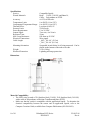
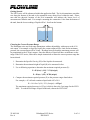
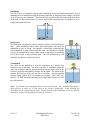
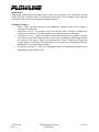
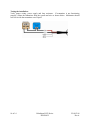
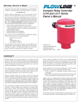
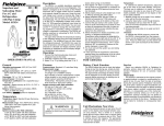
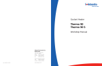
DeltaSpan
Waste Water Pressure
Level Transmitter Manual
LD32 Series
22 AUG 08
Rev A
Flowline, Inc.
10500 Humbolt Street
Los Alamitos, CA 90720
Tel: (562) 598-3015
Fax: (562) 431-8507
www.flowline.com
22 MAY 08
Rev A
DeltaSpan LD32 Series
MN301032
1 of 14
2 of 14
DeltaSpan LD32 Series
MN301032
22 AUG 08
Rev A
Preface
This manual explains how to use the DeltaSpan LD32 series waste water pressure level
transmitter.
Warranty, Service & Repair
To register your product with the manufacturer, go to the Flowline website for on-line
registration. The website address is as follows:
www.flowline.com
On-line Warranty Registration can be found under Contact Us in the Navigation Bar along the
side of the home page.
If for some reason your product must be returned for factory service, go to the Flowline website
to receive a Material Return Authorization number (MRA), providing the following information:
1. Full Part Number, Full Serial Number
2. Name and telephone number of someone who can answer technical questions related
to the product and its application.
3. Return Shipping Address
4. Brief Description of the Symptom
5. Brief Description of the Application
On-line Material Return Authorization can be found under Contact Us in the Navigation Bar
along the side of the home page. Click on Return Authorization to begin the MRA request.
Once you have received a MRA number, ship the product prepaid in its original packing to:
Flowline Factory Service
MRA_____
10500 Humbolt Street
Los Alamitos, CA 90720
To avoid delays in processing your repair, write the MRA on the shipping label. Please include
the information about the malfunction with your product. This information enables our service
technicians to process your repair order as quickly as possible.
22 MAY 08
Rev A
DeltaSpan LD32 Series
MN301032
3 of 14
Warranty
Flowline warrants to the original purchaser of its products that such products will be free from
defects in material and workmanship under normal use and service for a period which is equal to
the shorter of one year from the date of purchase of such products or two years from the date of
manufacture of such products.
This warranty covers only those components of the products which hare non-moving and not
subject to normal wear. Moreover, products which are modified or altered, and electrical cables
which are cut to length during installation are not covered by this warranty.
Flowline’s obligation under this warranty is solely and exclusively limited to the repair or
replacement, at Flowline’s option, of the products (or components thereof) which Flowline’s
examination proves to its satisfaction to be defective. FLOWLINE SHALL HAVE NO
OBLIGATION FOR CONSEQUENTIAL DAMAGES TO PERSONAL OR REAL
PROPERTY, OR FOR INJURY TO ANY PERSON.
This warranty does not apply to products which have been subject to electrical or chemical
damage due to improper use, accident, negligence, abuse or misuse. Abuse shall be assumed
when indicated by electrical damage to relays, reed switches or other components. The warranty
does not apply to products which are damaged during shipment back to Flowline’s factory or
designated service center or are returned without the original casing on the products. Moreover,
this warranty becomes immediately null and void if anyone other than service personnel
authorized by Flowline attempts to repair the defective products.
Products which are thought to be defective must be shipped prepaid and insured to Flowline’s
factory or a designated service center (the identity and address of which will be provided upon
request) within 30 days of the discovery of the defect. Such defective products must be
accompanied by proof of the date of purchase.
Flowline further reserves the right to unilaterally waive this warranty and to dispose of any
product returned to Flowline where:
a. There is evidence of a potentially hazardous material present with product.
b. The product has remained unclaimed at Flowline for longer than 30 days after
dutifully requesting disposition of the product.
THERE ARE NO WARRANTIES WHICH EXTEND BEYONDTHE DESCRIPTION ON THE
FACE OF THIS WARRANTY. This warranty and the obligations and liabilities of Flowline
under it are exclusive and instead of, and the original purchaser hereby waives, all other
remedies, warranties, guarantees or liabilities, express or implied. EXCLUDED FROM THIS
WARRANTY IS THE IMPLIED WARRANTY OF FITNESS OF THE PRODUCTS FOR A
PARTICULAR PURPOSE OR USE AND THE IMPLIED WARRANTY OF
MERCHANTABILITY OF THE PRODUCTS.
This warranty may not be extended, altered or varied except by a written instrument signed by a
duly-authorized officer of Flowline, Inc.
4 of 14
DeltaSpan LD32 Series
MN301032
22 AUG 08
Rev A
Introduction
The LD32 Series Waster Water Level Transmitter is manufactured for years of trouble free
service in the harshest applications. The pressure transmitter measures the height of liquid above
its position in the tank referenced to atmospheric pressure. The transmitter consists of a
piezoresistive sensing element, encased in 316 SS housing. Perfect for wastewater and slurry
applications, the LD32 series has features to protect the unit from these demanding applications.
Superior lightning and surge protection utilizing dual arrestor technology, grounded to case,
eliminating both power supply surges and lightning ground strike transients. Large diameter 316
SS diaphragm seal is non-clogging and damage resistant to floating solids.
The transmitter is equipped with a 270-pound tensile strength, shielded, vented cable.
Ventilation tube in the cable automatically compensates for changes in atmospheric pressure
above the tank. The vent tube has a filter attached to the end that will block particles, such as
dust, dirt, and water droplets, from entering the tube.
•
•
•
•
Excellent chemical compatibility with 316 construction and ETFE cable
Lightning and surge protection on all models
Maintenance free vent filter
Large diameter, non-clogging, damage resistant, 316 SS diaphragm seal
Table of Contents
Introduction ..........................................................................................................................5
About this Manual................................................................................................................6
Components .........................................................................................................................7
Technology ..........................................................................................................................7
Specifications .......................................................................................................................8
Dimensions ..........................................................................................................................8
Material Compatibility .........................................................................................................8
Getting Started .....................................................................................................................9
Choosing Correct Pressure Range ...........................................................................9
Effects of Specific Gravity.....................................................................................10
Electrical Installation .........................................................................................................11
Installation..........................................................................................................................12
Interference ............................................................................................................12
Termination ............................................................................................................12
Maintenance .......................................................................................................................13
Cleaning Procedure ................................................................................................13
Testing the transmitter ...........................................................................................14
22 MAY 08
Rev A
DeltaSpan LD32 Series
MN301032
5 of 14
About this Manual:
PLEASE READ THE ENTIRE MANUAL PRIOR TO INSTALLING OR USING THIS
PRODUCT. This manual includes information on all versions of the DeltaSpan Series Waste
Water Pressure Level Transmitter from Flowline; models LD32-____. Please refer to the part
number located on the transmitter label to verify the exact model which you have purchased.
User’s Responsibility for Safety:
Flowline manufactures a wide range of liquid level sensors and technologies. While each of
these technologies are designed to operate in a wide variety of applications, it is the user’s
responsibility to select a technology that is appropriate for the application, install it properly,
perform tests of the installed system, and maintain all components. The failure to do so could
result in property damage or serious injury.
Proper Installation and Handling:
Only properly-trained staff should install and/or repair this product. Use a proper sealant with all
installations. Always check for leaks prior to system start-up.
Wiring and Electrical:
A supply voltage of 13 to 30 VDC is used to power the LD32 series transmitter. Electrical
wiring of the sensor should be performed in accordance with all applicable national, state, and
local codes.
Temperature and Pressure:
The LD32 series is designed for use in application temperatures from -18° to 93°C (0° to 200°F),
and for use at pressures up to 2 x the full span of the LD32 series.
Material Compatibility:
The waste water pressure level transmitter, LD32 series, is made of 316 Stainless Steel (316 SS),
316L Stainless Steel (316L SS) with a cable of Polyurethane or Ethylene Tetrafluoroethylene
(ETFE). Make sure that the model which you have selected is chemically compatible with the
application liquids.
Flammable, Explosive and Hazardous Applications:
DO NOT USE THE DELTASPAN, LD32 SERIES LEVEL TRANSMITTER IN HAZARDOUS
LOCATIONS.
Make a Fail-Safe System:
Design a fail-safe system that accommodates the possibility of transmitter failure or battery
power loss. In critical applications, Flowline recommends the use of redundant backup systems
and alarms in addition to the primary system.
6 of 14
DeltaSpan LD32 Series
MN301032
22 AUG 08
Rev A
Components:
DeltaSpan is offered in eight different models, based upon pressure rating and material.
Depending on the model purchased, you may or may not have been shipped all the components
shown below. .
•
•
DeltaSpan
o LD32-S101
o LD32-S111
o LD32-S121
o LD32-S131
o LD32-S201
o LD32-S211
o LD32-S221
o LD32-S231
Quick Start Guide
– 05 psi
– 10 psi
– 15 psi
– 20 psi
– 05 psi
– 10 psi
– 15 psi
– 20 psi
(11.54 ft wc / 3.52 m wc),
(23.09 ft wc / 7.04 m wc),
(34.63 ft wc / 10.56 m wc),
(46.18 ft wc / 14.08 m wc),
(11.54 ft wc / 3.52 m wc),
(23.09 ft wc / 7.04 m wc),
(34.63 ft wc / 10.56 m wc),
(46.18 ft wc / 14.08 m wc),
40’ (12.2 m) Polyurethane Cable
40’ (12.2 m) Polyurethane Cable
60’ (18.3 m) Polyurethane Cable
60’ (18.3 m) Polyurethane Cable
40’ (12.2 m) ETFE Cable
40’ (12.2 m) ETFE Cable
60’ (18.3 m) ETFE Cable
60’ (18.3 m) ETFE Cable
Technology
A sealed pressure transmitter is placed near or on the bottom of the tank. A stainless steel
pressure diaphragm within the pressure transmitter is exposed on one side to the application
liquid. The other side is exposed to the reference pressure via a small ventilation tube located
inside of the Polyurethane cable. A difference in pressure between liquid and reference
pressures will slightly deflect the diaphragm. The deflection of the diaphragm is measured by a
built-in microprocessor that provides greater linearity correction over common thermal
compensation methods. A 4-20 mA current signal proportional the height of the liquid is
generated from the microprocessor.
22 MAY 08
Rev A
DeltaSpan LD32 Series
MN301032
7 of 14
Specifications
Service:
Wetted Materials:
Accuracy:
Temperature Limit:
Compensated Temperature Range:
Thermal Effect:
Pressure Limit:
Power Requirement:
Output Signal:
Response Time:
Max. Loop Resistance:
Electrical Connections:
Cable Length
Mounting Orientation:
Weight:
Electrical Protection:
Compatible liquids.
Body: 316 SS, 316L SS, and Buna-N;
Cable: Polyurethane or ETFE.
±0.25% of full scale.
0 to 200ºF (-18 to 93ºC).
0 to 180ºF (-18 to 82ºC).
Less than ±0.02%/°F.
2X full scale.
13 to 30 VDC.
Two-wire, 4 to 20 mA.
50 ms.
850 ohms at 30 VDC.
Wire pigtail.
-_001/-_101: 40’ (12.2 m)
-_201/-_301: 60’ (18.3 m)
Suspended in tank below level being measured. Can be
placed on the bottom of the tank on its side.
4.3 lb (2.0 kg).
Lightning and surge protection.
Dimensions
Material Compatibility:
o The LD32 series is made of 316 Stainless Steel (316 SS), 316L Stainless Steel (316L SS)
with a cable of Polyurethane or Ethylene Tetrafluoroethylene (ETFE).
o Make sure that the switch is compatible with the application liquids. To determine the
chemical compatibility between the sensor and its application liquids, refer to the
Compass Corrosion Guide, available from Compass Publications (858-589-9636).
8 of 14
DeltaSpan LD32 Series
MN301032
22 AUG 08
Rev A
Getting Started
The LD32 series will be submersed within the application fluid. The level transmitters can either
rest along the bottom of the tank or be suspended at any desired level within the tank. Please
note that the physical location of the level transmitter will indicate the lowest level of
measurement within the tank. For example: mounting the transmitter 1 foot from the bottom of
the tank, then the lowest reading of liquid will be 1 foot from the bottom.
Choosing the Correct Pressure Range
The DeltaSpan series are fixed range transmitters with no adjustability with respect to the 4-20
mA output. For example: at 0 psi (no liquid), the current output will be 4 mA and at maximum
pressure, the current output will be 20 mA. Readings between 0 and the maximum pressure will
be proportional to the 4-20 mA output. Since the density of liquid will have an influence on the
range of the LD32 series, follow these simple instructions to insure the correct pressure range has
been selected.
1. Determine the Specific Gravity (SG) of the liquid to be measured.
2. Determine the maximum height of liquid (H) to be measured in feet.
3. Use to following equation to determine the maximum required pressure (P):
P = H (feet) * (SG) / 2.31 (feet/psi)
or
P = H (m) * (SG) / 0.704 (m/psi)
4. Compare the maximum required pressure (P) to the pressure ranges listed above.
For example, a 16’ tall tank contains a liquid with a SG of 0.9:
P = 16.0 feet * (0.9) / 2.31 (feet/psi) = 6.23 psi
The maximum required pressure is 6.23 psi, which is above the 5 psi range for the LD32S001. To read the full range of liquid in the tank, choose the LD32-S101.
22 MAY 08
Rev A
DeltaSpan LD32 Series
MN301032
9 of 14
Effects of Specific Gravity:
The LD32 series has a fixed span with 4 mA equal to 0 psi and 20 mA equal to the maximum psi
setting. Each unit is calibrated for use in liquids with a specific gravity (SG) of 1.000. Pressure
transducers maybe used in liquids with a SG other than 1.000. Please note the following
relationship between the pressure range and specific gravity:
1 psi = 2.31 feet @ SG = 1.000
or
1 psi = 0.704 m @ SG = 1.000
For example, the LD32-S001 has a range of 0 to 5 psi. The maximum depth the transmitter can
read in water (SG = 1.000) is 5 psi x (2.31 feet / 1 psi) = 11.5 feet. For metric, the maximum
depth in water is 5 psi x 0.704 m / psi) = 3.52 m.
For liquids with a different SG, simply divide 2.31 by the new SG to determine the new ratio.
For example, the LD32-S001 is installed in a liquid with a SG = 0.85. The new ratio is as
follows:
1 psi = 2.31 feet / (0.85) = 2.717 feet (0.828 m)
Multiply 5 psi by the new ratio to determine the maximum depth:
5 psi * (2.717 feet / 1 psi) = 13.6 feet (4.15 m)
A lower SG will increase the maximum depth for the transmitter. Another example, the LD32S101 is installed in a liquid with a SG = 1.2. The new ratio is as follows:
1 psi = 2.31 feet / (1.2) = 1.925 feet (0.587 m)
Multiply 10 psi by the new ratio to determine the maximum depth:
10 psi * (1.925 feet / 1 psi) = 19.3 feet (5.87 m)
A high SG will decrease the maximum depth for the transmitter.
10 of 14
DeltaSpan LD32 Series
MN301032
22 AUG 08
Rev A
Electrical Installation
An external power supply delivering 13-30 VDC with minimum current capability of 40 mA DC
(per transmitter) is required to power the control loop. See figure below for connection of the
power supply, transmitter and receiver.
The maximum receiver load resistance (RLmax) for the DC power supply voltage (Vsup) is
expressed by the formula:
RLmax = (Vsup – 13V) / 0.02A
Shielded cable is recommended for control loop wiring. Use the Red wire as the (+) and the
Black wire as the (-).
Wiring to a Loop Powered Display
Wiring to a Typical PLC
22 MAY 08
Rev A
DeltaSpan LD32 Series
MN301032
11 of 14
Installation
The LD32 series is designed to operate while submerged in the actual application liquid. Avoid
installing the level transmitter along the bottom of the tank is materials such as sludge will build
up and coat/cover the transmitter. This also includes any debris that will settle along the bottom
of the tank. In these applications, it is best to suspend the transmitter above the highest level of
sludge/debris that will occur.
Interference
The DeltaSpan is designed to operate under the surface of the liquid in the
tank. Avoid installations where other tank requirements will cause the
transmitter to move or swing. For example: a mixer blade could cause the
level transmitter to whip around within the tank. An alternative would be
to move the transmitter to a more stable section of the tank or to install the
LD32 series inside a still well/drop tube. The still well/drop pipe will
minimize the effects created by the mixer.
Termination
The cable for the DeltaSpan is typically terminated at a junction box
located on top of the tank. Since the vent tube is contained within the
cable, the pressure within the junction box must always be the same as the
reference (typically atmospheric) pressure for the liquid. The inside of the
junction box must be clean, dry and free of moisture. Add the optional
pressure fitting (LD90-_001) to complete the package. The LD90-_001
features a 2” NPT thread for mounting and a liquid tight connector to seal
the cable interface.
Note: Use caution when sealing the cable at the top of the tank. The ventilation tube must be
open and free to allow air to flow back to the pressure diaphragm. Avoid blocking the
ventilation tube by compressing the cable. Always keep the cable termination clean, dry and free
of moisture and prevent liquid from entering the vent tube.
12 of 14
DeltaSpan LD32 Series
MN301032
22 AUG 08
Rev A
Maintenance
Maintenance should consist of inspection to see that the transmitter is free from debris and not
coated with any substance, which would prevent liquid from freely entering and leaving the
transmitter. If this occurs, the transmitter should be cleaned.
Cleaning procedure:
1. Power: Make sure that all power to the transmitter, controller and/or power supply is
completely disconnected.
2. Transmitter removal: If necessary, make sure that the tank is drained well below the
switch prior to removal. Carefully, remove the transmitter from the installation.
3. Cleaning the switch: Using a soft bristle brush and mild detergent, carefully wash the
switch. Do not use harsh abrasives such as steel wool or sandpaper, which might damage
the surface of the sensor. Do not use incompatible solvents, which may damage the
sensor's stainless steel body. Take particular care to remove any scaling from the body
and that there is no debris inside the inlet.
4. Transmitter installation: Follow the appropriate steps of installation as outlined in the
Installation section of this manual.
22 MAY 08
Rev A
DeltaSpan LD32 Series
MN301032
13 of 14
Testing the installation:
Verify proper wiring, power supply and loop resistance. If transmitter is not functioning
properly, isolate the transmitter from the system and wire as shown below. Multimeter should
read 4 mA with the transmitter out of liquid.
14 of 14
DeltaSpan LD32 Series
MN301032
22 AUG 08
Rev A