1
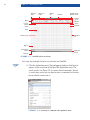
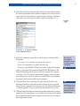
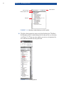
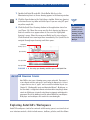
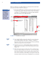
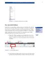
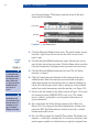
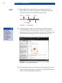
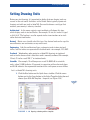
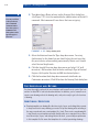
Chapter 1 Getting Started As we begin this chapter on getting started with AutoCAD, I’m reminded TE RI AL of a quote by Lao-Tzu: “A journey of a thousand miles begins with a single step.” In much the same way, learning AutoCAD is something anyone can do by taking it one step at a time. And I promise AutoCAD is much easier than walking a thousand miles! Congratulations if you are reading this: You are now on your way. By the end of this book, you will have a solid understanding of AutoCAD. Setting drawing units MA Exploring the AutoCAD 2012 for Windows User interface TE D Exploring the AutoCAD 2012 for Windows User Interface GH RI PY AutoCAD for Mac has a user interface that is customized to the Mac experience. Although the Mac user interface is not covered in this book, its commands and capabilities are similar to those in AutoCAD for Windows. Autodesk has released several versions of AutoCAD, including AutoCAD 2012, AutoCAD LT 2012, and AutoCAD 2012 for the Mac. The two Windows versions look nearly identical and function in almost the same way. The main difference is that LT doesn’t support automation and some of the advanced 3D functions. The Mac version looks a bit different than its cousins but functions nearly identically to AutoCAD for Windows. Although this book was written using AutoCAD 2012 running on Windows XP Professional, you can use it to learn any of the current versions of AutoCAD. CO Exploring AutoCAD’s Graphical User Interface Before you can use AutoCAD, you’ll need to thoroughly familiarize yourself with its graphical user interface (GUI). The AutoCAD 2012 (for Windows) user interface is shown in Figure 1.1. Chapter 1 • Getting Started 2 Application menu Quick Access toolbar Drawing title InfoCenter AutoCAD-specific Windows controls Drawingspecific Windows controls Ribbon In-canvas viewport controls ViewCube Cursor Navigation bar Drawing canvas UCS icon Command line window Application handle Status bar F igu r e 1 . 1 AutoCAD 2012 user interface Let’s now step through the basic user interface for AutoCAD: Certification Objective 1. Click the Application menu. Type polygon and observe that the text appears in the search box at the top of the Application menu. The search results (see Figure 1.2) list many related commands. Search is useful when you’re not sure how to access a command in the interface or what its exact name is. F igu r e 1 . 2 Searching for commands in the Application menu E xploring the AutoC AD 2012 for Windows User Inter face 3 2. Click the red X at the extreme right edge of the search box to make the initial Application menu interface reappear; here you can create new or open existing drawings, export or print drawings, and more. Hover the cursor over Open and then click Drawing (Figure 1.3). Certification Objective F igu r e 1 . 3 Opening a drawing from the Application menu 3. Select the following sample file and click Open in the Select File dialog box: C:\Program Files\Autodesk\AutoCAD 2012\Sample\ Sheet Sets\Manufacturing\VW252-02-0142.dwg Sheet sets are not available in AutoCAD LT and are an optional feature in AutoCAD. If you are using AutoCAD LT open any of the sample files located under: C:\Program Files\Autodesk\AutoCAD LT 2012\Sample. The Sheet Set Manager palette appears when the sample file is opened (see Figure 1.4). This palette automatically appears when you open any drawing that’s a part of a sheet set. AutoCAD has many palettes to organize tools and reusable drawing content. 4. Click the Sheet Views tab along the right edge of the Sheet Set Manager and observe that tabs provide a means of accessing additional interface content. In its present state, the Sheet Set Manager is a floating palette. Drag its palette bar and relocate it on screen. O 5. Click the Auto-hide toggle and watch the palette collapse to its vertical palette bar; this saves space on screen. Hover the cursor over the palette bar and watch the whole palette reappear so you can access its content. Now toggle Auto-hide off. Drag floating palettes to a secondary monitor to maximize the drawing area on your primary monitor. 4 Chapter 1 • Getting Started Auto-hide toggle Tabbed interface Palette properties menu Palette bar F igu r e 1 . 4 Opening a sample drawing reveals this palette. 6. Click the palette properties menu and select Anchor Left. The Sheet Set Manager palette is docked along the left edge of the user interface (see Figure 1.5). There are many options you can use to organize the user interface to match the way you work. F igu r e 1 . 5 Docking a palette E xploring the AutoC AD 2012 for Windows User Inter face 7. Double click Detail-B under 04 – Brush Roller Sub Assy in the Manufacturing sheet set. A new drawing appears in the drawing window. 8. Click the Open button in the Quick Access toolbar. Select any drawing in the Manufacturing folder and click Open. If you are using LT, open any other sample file. 5 9. Click the Quick View Drawings button in the application status bar (see Figure 1.6). Move the cursor over the first drawing and observe that two smaller views appear above it; these are the highlighted drawing’s spaces. Move the cursor over Model and its view enlarges. Click the model view icon to go there immediately. Use Quick View to navigate through open drawings and their spaces. Highlighted drawing’s spaces Open drawings Close Quick View Open Quick View F igu r e 1 . 6 Accessing open drawings and their spaces with Quick View A u t o C A D D r aw i n g S pac e s AutoCAD has two types of drawing spaces: paper and model. Paperspace is a two-dimensional area analogous to and having the dimensions of a sheet of paper. Various sizes of “paper” can be created in individual layouts (see Chapter 13, “Working with Layouts and Annotative Objects”). Modelspace, on the other hand, is a single three-dimensional volume where everything is drawn actual size. Modelspace is typically scaled down in viewports and displayed in paperspace. Most of the drawing you will do in AutoCAD will be in modelspace. Both paper- and modelspaces are saved in the same drawing file. Exploring AutoCAD’s Workspaces AutoCAD workspaces (not to be confused with drawing spaces) are stored sets of user interface controls, which include menus, toolbars, palettes, and the ribbon. Certification Objective O The Quick Access toolbar is a convenient way to open drawings, especially when you’re not using the Sheet Set Manager. Chapter 1 • Getting Started 6 People use workspaces to quickly configure the interface for the task at hand. Let’s take a brief look at AutoCAD’s workspaces: Although longtime users might feel more comfortable with the AutoCAD Classic interface, there are many advantages to using all the workspaces. 1. Select the AutoCAD Classic workspace from the drop-down menu on the Quick Access toolbar. The user interface changes dramatically (see Figure 1.7). The AutoCAD Classic workspace makes AutoCAD look similar to how it did in 2008 and before. Classic menu bar Floating toolbars Docked toolbars Scrollbars F igu r e 1 . 7 AutoCAD Classic workspace Certification Objective 2. Drag a docked toolbar out from the edge of the screen and convert it into a floating toolbar. Select Tools ➢ Toolbars ➢ AutoCAD ➢ Dimension from the classic menu bar. Drag the Dimension floating toolbar to any edge of the screen and dock it. Certification Objective 3. Position the cursor over a docked toolbar button and right-click; a toolbar context menu appears. Select Object Snap from this menu (Figure 1.8). 4. Right-click in the drawing window and you’ll see a different context menu. Right-clicking over most items, from the tool palettes to the status bar buttons, brings up other unique context menus. In the Classic workspace, right-clicking is the means of accessing numerous context-sensitive menus throughout the user interface. E xploring the AutoC AD 2012 for Windows User Inter face 7 F igu r e 1 . 8 Using the context menu to open toolbars The AutoCAD Ribbon AutoCAD has so many toolbars, palettes, and menus that finding the right tool for the job can seem like a job in itself. The ribbon was therefore an important feature that was introduced to AutoCAD. Autodesk adopted Microsoft’s ribbon standard to organize the ever-increasing number of toolbars in a single special palette, making tools much easier to find. Let’s now explore various ribbon modes and identify the user interface elements of each. 1. Choose the 3D Basics workspace from the drop-down menu in the Quick Access toolbar. The ribbon replaces all the classic menus and toolbars (see Figure 1.9). Close the tool palettes and the Online floating toolbar. Tabbed interface Minimize ribbon Typical panel F igu r e 1 . 9 The full ribbon interface 2. Click the Minimize Ribbon button and observe the full ribbon change to display tabs and panel buttons (see Figure 1.10). Hover the cursor O The ribbon isn’t shown in the AutoCAD Classic workspace. Certification Objective Chapter 1 • Getting Started 8 over the panel buttons. The buttons expand to reveal all the tools shown on the full ribbon. Panel buttons Panel titles Tabs F igu r e 1 . 1 0 Ribbon modes Certification Objective I recommend using the full ribbon interface until you learn where all the tools are. Using one of the minimized modes saves space on screen. 3. Click the Minimize Ribbon button again. The panel buttons change into titles. Again hover the cursor over the titles to reveal each panel’s tools. 4. Click the Minimize Ribbon button once again. Hovering the cursor over the tabs doesn’t have any effect. Click the Home tab to reveal the full panel temporarily. It disappears after you move the cursor away. 5. Click the Minimize Ribbon button one last time. The full ribbon interface is restored. 6. Click the Create button at the bottom of the Create panel to reveal additional tools. Hover the mouse over one of the tools to display a tooltip that identifies the tool and describes its function. Holding the cursor still a while longer reveals either a drawing or a video (without audio) that visually demonstrates what the tool does (see Figure 1.11). 7. Observe that the bottom of the tooltip shown in Figure 1.11 reveals the command name (SURFSCULPT in this case). The ribbon, menus, toolbars, and palettes are all graphical alternatives to typing commands. 8. Press and release the Alt key. Keytips appear on the ribbon (see Figure 1.12). Pressing any of the letter combinations activates that part of the GUI. Type IN and observe that the Insert tab is selected without moving the cursor. 9. Press the F2 key to open the AutoCAD Text window. The bottom line, Command:, is called the command line. It is the active line where commands appear regardless of whether they are typed or triggered from AutoCAD is based on commands. If you know the name of a command, you can type it instead of finding it in the GUI. E xploring the AutoC AD 2012 for Windows User Inter face 9 the GUI. The complete history of commands scrolls upward as new commands are entered. Close the AutoCAD Text window. Three lines of this command history appear at the bottom of the user interface, just above the application status bar. F igu r e 1 . 1 1 Tooltip and video F igu r e 1 . 1 2 Keytips allow you to press keys to manipulate the ribbon with the keyboard. 10. The application status bar contains a coordinate readout on the left, a number of status toggle buttons, and various items, as shown in Figure 1.13. Click the application status bar menu and deselect Clean Screen; its button disappears. You can control which buttons appear using this menu. Clean screen Coordinate readout Status toggles Quick View controls Specialized tools Tray Paper/Model Drawing status bar F igu r e 1 . 1 3 Application, drawing status bars, and the tray Application status bar menu O The drawing status bar contains items that are saved in the current drawing, whereas the application status bar contains items that are not specific to a particular drawing. Chapter 1 • Getting Started 10 Certification Objective 11. Take a look at the InfoCenter at the top right of the screen (see Figure 1.14); this is where you connect to Autodesk and the larger community. Click in the search field and type solid. Search box Search button Autodesk online services Exchange Help F igu r e 1 . 1 4 InfoCenter The AutoCAD Exchange dialog box contains help, the Autodesk store, and access to the AutoCAD community. 12. Click the binoculars icon on the right of the search field and the AutoCAD Exchange dialog box appears. Multiple online books are searched and relevant results appear in the left panel. The description of the SOLID command appears in the right panel (Figure 1.15). F igu r e 1 . 1 5 AutoCAD Exchange 13. Click the Help button on the right edge of the InfoCenter. The Help Table of Contents page opens in your browser. All AutoCAD documentation is accessible through this interface. Setting Drawing Units 11 Setting Drawing Units Before you start drawing, it’s important to decide what one drawing unit represents in the real world. Architects in the United States typically equate one drawing unit with one inch in AutoCAD. You need to choose a unit type that matches your country’s industry standard. Architectural A s the name suggests, most architects will choose this type, which displays units in feet and inches. For example, 12 feet, 61⁄2 inches is typed as 12´6-1/2˝. The hyphen is used to separate inches from fractions of an inch rather than feet from inches. Decimal Metric users should select this type. One decimal unit can be equal to one millimeter, one centimeter, or any metric unit. Engineering Like the architectural type, engineering units feature feet and inches, but the inches are represented in decimal form—for example, 12´6.500˝. Fractional Woodworkers often prefer to set AutoCAD drawings in fractional units of inches because that is how their work is normally reckoned. For example, 12 feet, 61⁄2 inches reads 150-1⁄2˝ in fractional units. Scientific For example, 12 million parsecs reads 12.000E+06 in scientific units, where 12.000 indicates 12 accurate to a precision of three decimal places and E+06 indicates the exponential function to the sixth power, or one million. Let’s set AutoCAD’s drawing units: 1. Click the New button on the Quick Access toolbar. Click the arrow button next to the Open button in the Select Template dialog box and choose Open With No Template – Imperial (see Figure 1.16). Certification Objective F igu r e 1 . 1 6 Opening a drawing with no template Chapter 1 • Getting Started 12 You can press Enter or the spacebar to enter commands (command names never have spaces). Commands and their options can be typed in upper or lowercase. 2. Type UN and press Enter to bring up the Drawing Units dialog box (see Figure 1.17). UN is the command alias (abbreviation) of the UNITS command. Most commands have aliases that save on typing. F igu r e 1 . 1 7 Setting drawing units 3. Select Architectural from the Type drop-down menu. I’m using Architectural in this book, but you should select the unit type that fits your industry when working professionally. Metric users should select Decimal length units. 4. Click the Length Precision drop-down menu and select 1/8˝ (or 0 for metric). Set Insertion Scale to Inches and Angle Type to Decimal Degrees. Set Angular Precision to 0.00 (two decimal places). 5. Click the Insertion Scale drop-down menu and select Inches (or Centimeters for metric). Click OK to close the Drawing Units dialog box. T h e E ss e n t i a l s a n d B e yo n d You have thoroughly explored the user interface and learned how to control the look and feel of AutoCAD to suit task-based workflows. In addition, you’ve learned how to create a new drawing and set the drawing units, and you’re ready to get to the business of drawing. A dd i t i o n a l E x e r c i s e s Drawing templates are drawing files that store styles, layers, and settings that you want to keep consistent in every drawing you create. Set up the drawing units according to the way you work and save a new template file (.dwt). Then create a new drawing file (.dwg) based on your template and verify that the units are as expected. As you learn more about styles, layers, and settings later in this book, you can add your preferences to this template file. Be aware that templates do not affect preexisting drawings.