1
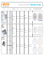
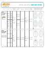
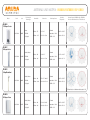
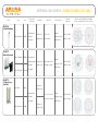
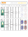
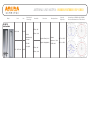
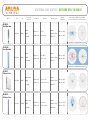
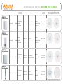
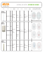
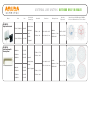
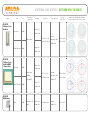
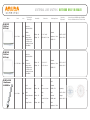
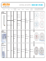
ANTENNA LINE MATRIX: INDOOR ONLY (RP-SMA)
Model
Band
Gain
Polarization &
Element Type
Beamwidth
Dimensions
Max Input Power
Operating
Temperature
AP-ANT-1B
Direct-Mount Omni
2.4 - 2.5 GHz
E-Plane – 50º
3.8 dBi
H-Plane - 360º
Vertical, Linear
1.54” x 0.75” x 5.00”
RP-SMA
3.9 x 1.9 x 12.7 cm
2 watts
Impedence - 50 Ω
VSWR <2.0:1
14º F to 131º F
-10º C to +55º C
E-Plane – 25º
4.900 – 5.875 GHz
5.8 dBi
H-Plane - 360º
AP-ANT-2
Ceiling Mount Omni
Vertical, Linear
2.4-2.5 GHz
6.0 dBi
Linear Array
RP-SMA
E-Plane – 18º
10.86” x 1.06”
H-Plane - 360º
27.6 x 2.7 cm
50 watts
Impedence - 50 Ω
VSWR <2.0:1
-40º F to 158º F
-40º C to +70º C
AP-ANT-3
Bidirectional Patch
Vertical, Linear
2.4-2.5 GHz
5.0 dBi
Linear Patch
RP-SMA
36” pigtail
E-Plane – 40º
H-Plane - 60º
Bidirectional
2.72” x 2.52” x 0.79”
6.9 x 6.4 x 2 cm
50 watts
Impedence - 50 Ω
VSWR <1.8:1
-40º F to 158º F
-40º C to +70º C
Antenna Pattern (2450Mhz and/or 5500Mhz)
Direction of Maximum Gain at 0o Unless Noted
ANTENNA LINE MATRIX: INDOOR ONLY (RP-SMA)
Model
Band
Gain
Polarization &
Element Type
Beamwidth
Dimensions
Max Input Power
Operating
Temperature
Antenna Pattern (2450Mhz and/or 5500Mhz)
Direction of Maximum Gain at 00 Unless Noted
AP-ANT-4
High-Gain Patch
Linear
2.4-2.5 GHz
9.0 dBi
Air-loaded patch
E-Plane – 60º
5.08” x 5.08” x 0.87”
RP-SMA
H-Plane - 60º
12.9 x 12.9 x 2.22 cm
E-Plane – 50º
4.09” x 4.09” x 0.87”
H-Plane - 360º
10.4 x 10.4 x 2.2cm
36” pigtail
AP-ANT-5
Low-Gain
Downtilt Omni
50 watts
Impedence - 50 Ω
VSWR <1.5:1
-40º F to +158º F
-40º C to +70º C
Downtilt
2.4-2.5 GHz
3.5 dBi
Omnidirectional
patch
RP-SMA
50 watts
Impedence - 50 Ω
VSWR <1.5:1
-40º F to +158º F
-40º C to +70º C
36” pigtail
E-Plane Direction of Maximum Gain at 180º
AP-ANT-13B
Downtilt Omni
2.4-2.5 GHz
4.4 dBi
Vertical, Linear
Downtilt
RP-SMA
30” pigtail
4.9-5.9 GHz
3.3 dBi
E-Plane – 60º
2.16” x 2.16” x 0.63”
H-Plane - 360º
5.5 x 5.5 x 1.6cm
2 watts
Impedence - 50 Ω
VSWR <2.0:1
-40º F to +158º F
-40º C to +70º C
ANTENNA LINE MATRIX: INDOOR ONLY (RP-SMA)
Model
AP-ANT-14
Dual-Band Downtilt
Diversity Omni
Band
Gain
2.400 GHz
3.67 dBi
2.450 GHz
2.55 dBi
2.500 GHz
2.83 dBi
Polarization &
Element Type
Beamwidth
Dimensions
Max Input Power
Operating
Temperature
E-Plane – 57-61º
H-Plane - 360º
Downtilt
Vertical, Linear
6.16” x 0.89” x 3.66”
RP-SMA
15.65 x 2.26 x 9.3cm
4.900 GHz
5.14 dBi
5.150 GHz
4.10 dBi
E-Plane – 55-59º
5.550 GHz
3.32 dBi
H-Plane – 360º
5.990 GHz
3.31 dBi
2.4-2.5 GHz
3.9 dBi
2x36” pigtails
2 watts
Impedence - 50 Ω
VSWR <2.0:1
-40º F to +158º F
-40º C to +70º C
AP-ANT-16
Downtilt Omni MIMO
3-Element Array
Vertical
Downtilt
E-Plane – 60º
12.13” x 3.62” x 0.86”
3x RP-SMA
H-Plane – 360º
30.82 x 9.2 x 2.2 cm
3x 36” pigtails
4.9-5.9 GHz
4.7 dBi
2 watts
Impedence - 50 Ω
VSWR <2.0:1
-40º F to +158º F
-40º C to +70º C
Antenna Pattern (2450Mhz and/or 5500Mhz)
Direction of Maximum Gain at 00 Unless Noted
ANTENNA LINE MATRIX: INDOOR/OUTDOOR (RP-SMA)
Model
Band
Gain
Polarization &
Element Type
Beamwidth
Dimensions
Max Input Power
Operating
Temperature
Antenna Pattern (2450Mhz and/or 5500Mhz)
Direction of Maximum Gain at 00 Unless Noted
AP-ANT-6
135 Degree Sector
Linear
2.4-2.5 GHz
5.0 dBi
RP-SMA
36” pigtail
E-Plane – 55º
6” x 3” x 2”
H-Plane – 135º
15.2 x 7.6 x 5 cm
E-Plane – 10º
3” x 26” x 1”
H-Plane – 90º
7.6 x 66 x 2.5 cm
E-Plane – 30º
11.5” x 7.1” x 0.98”
H-Plane – 360º
29.2 x 18 x 2.5 cm
50 watts
Impedence - 50 Ω
VSWR <1.5:1
-40º F to +158º F
-40º C to +70º C
AP-ANT-7
90 Degree Sector
Vertical, Linear
2.4-2.5 GHz
12.0 dBi
RP-SMA
36” pigtail
50 watts
Impedence - 50 Ω
VSWR <2.0:1
-22º F to +149º F
-30º C to +65º C
AP-ANT-8
Ceiling Mount Omni
Vertical, Linear
2.4-2.5 GHz
5.0 dBi
RP-SMA
36” pigtail
50 watts
Impedence - 50 Ω
VSWR <1.5:1
-40º F to +158º F
-40º C to +70º C
E-Plane Direction of Maximum Gain at 90º & 270º
AP-ANT-9
90 Degree Sector
Vertical, Linear
2.4-2.5 GHz
7.0 dBi
RP-SMA
36” pigtail
E-Plane – 60º
4.6” x 2.6” x 0.99”
H-Plane – 90º
11.8 x 6.8 x 2.5 cm
25 watts
Impedence - 50 Ω
VSWR <1.5:1
-40º F to +158º F
-40º C to +70º C
ANTENNA LINE MATRIX: INDOOR/OUTDOOR (RP-SMA)
Model
Band
Gain
Polarization &
Element Type
Beamwidth
Dimensions
Max Input Power
Operating
Temperature
Antenna Pattern (2450Mhz and/or 5500Mhz)
Direction of Maximum Gain at 00 Unless Noted
AP-ANT-10
Ceiling Mount Omni
Vertical, Linear
5.150 - 5.875 GHz
6.0 dBi
RP-SMA
36” pigtail
E-Plane – 18º
11.5” x 1.0”
H-Plane - 360º
29.2 x 2.54cm
10 watts
Impedence - 50 Ω
VSWR <2.0:1
-40º F to +158º F
-40º C to +70º C
E-Plane Direction of Maximum Gain at 90º & 270º
AP-ANT-12
High-Gain Directional
5.150 - 5.350 GHz
14.0 dBi
5.470 - 5.875 GHz
13.25 dBi
2.4-2.5 GHz
5.0 dBi
Vertical, Linear
Directional patch
E-Plane – 30º
4.02” x 4.02” x 1.38”
RP-SMA
H-Plane - 30º
10.2 x 10.2 x 3.5cm
36” pigtail
AP-ANT-15
120 Degree Sector
Dual-Band
VSWR <2.0:1
-40º F to +158º F
-40º C to +70º C
H-Plane - 120º
2.16” x 5.16” x 1.38”
RP-SMA
5.49 x 13.11 x 3.51cm
36” pigtail
5.0 dBi
Impedence - 50 Ω
E-Plane – 65º
Vertical, Linear
4.900 – 5.875 GHz
10 watts
E-Plane – 65º
H-Plane - 120º
5 watts
Impedence - 50 Ω
VSWR <2.0:1
-40º F to +158º F
-40º C to +70º C
ANTENNA LINE MATRIX: INDOOR/OUTDOOR (RP-SMA)
Model
Band
Gain
2.4-2.5 GHz
6.0 dBi
Polarization &
Element Type
AP-ANT-17
120 Degree Sector
Dual-Band MIMO
Beamwidth
Max Input Power
Operating
Temperature
Antenna Pattern (2450Mhz and/or 5500Mhz)
Direction of Maximum Gain at 00 Unless Noted
E-Plane – 65º
H-Plane - 120º
Vertical, Linear
7.9” x 7.9” x 1.26”
3x RP-SMA
20.1 x 20.1 x 3.2 cm
3x 30” pigtail
4.900 – 5.875 GHz
Dimensions
50 watts
Impedence - 50 Ω
VSWR <1.7:1
-40º F to +158º F
-40º C to +70º C
E-Plane – 75º
5.0 dBi
H-Plane - 150º
AP-ANT-18
60 Degree Sector
Dual-Band MIMO
75
10
60
165
120
150
135
-10
150
-15
-165
-30
7.87” x 7.87” x 1.30”
Dual slant
200 x 200 x 33 mm
+/-45 degrees
20 watts
Impedence - 50 Ω
VSWR <1.8:1
75
-75
60
75
-40º C to +70º C
-60
45
10
30
-30
15
165
105
60
-150
-10
120
150
5.15 – 5.875 GHz
7.5 dBi
H-Plane - 60º
165
180
-40
-15
-165
-30
-150
-45
-135
-60
-120
-75
-120
-20
-30
0
-135
-10
-20
E-Plane – 60º
10
-15
-165
0
135
135
30
15
0
-180
150
120
0
45
-45
-105
90
-90
-40
-120
-90
-105
-35
-135
-60
-75
-120
-30
90
-150
-45
-40º F to +158º F
-135
-25
105
180
-40
-15
Linear, Vertical
-150
-15
-35
H-Plane - 60º
-165
-10
120
165
-30
0
-180
0
-5
-20
-25
15
10
5
135
-20
E-Plane – 60º
7.5 dBi
105
0
-5
30
2.4-2.5 GHz
90
5
45
-90
-105
105
-105
-30
90
-90
-40
75
-75
60
-60
45
-45
-30
30
15
0
-15
ANTENNA LINE MATRIX: INDOOR/OUTDOOR (RP-SMA)
Model
Band
Gain
Polarization &
Element Type
Beamwidth
Dimensions
Max Input Power
Operating
Temperature
AP-ANT-19
Dual-Band Omni
2.4-2.5 GHz
E-Plane – 50º
3.0 dBi
Vertical
H-Plane - 360º
Omnidirectional
coverage
Height: 245 mm (9.6 in)
Weight: 140 kg (0.30 lb)
RP-SMA
36” pigtail
5.15 – 5.875 GHz
6.0 dBi
E-Plane – 20º
H-Plane - 360º
10 watts
Impedence - 50 Ω
VSWR <2.0:1
-40º F to +158º F
-40º C to +70º C
Antenna Pattern (2450Mhz and/or 5500Mhz)
Direction of Maximum Gain at 00 Unless Noted
ANTENNA LINE MATRIX: OUTDOOR ONLY (N-MALE)
Model
Band
Gain
Polarization &
Element Type
Beamwidth
Dimensions
Max Input Power
Operating
Temperature
Antenna Pattern (2450Mhz and/or 5500Mhz)
Direction of Maximum Gain at 00 Unless Noted
AP-ANT-80
Mast Mount Omni
Vertical
2.4-2.5 GHz
8.0 dBi
N-Male
36” pigtail
E-Plane – 13º
25” x 1”
H-Plane – 360º
63.5 x 2.5 cm
20 watts
Impedence - 50 Ω
VSWR <1.5:1
-40º F to +158º F
-40º C to +70º C
E-Plane Direction of Maximum Gain at 90º & 270º
AP-ANT-80D
Direct Mount Omni
Vertical
2.4-2.5 GHz
8.0 dBi
N Male
Direct Mount
E-Plane – 13º
19.5” x 0.75”
H-Plane - 360º
49.5 x 1.9 cm
50 watts
Impedence - 50 Ω
VSWR 1.7:1
-40º F to +158º F
-40º C to +70º C
E-Plane Direction of Maximum Gain at 90º & 270º
AP-ANT-81
60 Degree Sector
Vertical, Linear
2.4-2.5 GHz
8.0 dBi
N-Male
36” pigtail
E-Plane – 60º
6” x 6” x 1.25”
H-Plane – 65º
15.2 x 15.2 x 3.2 cm
E-Plane – 10º
3” x 26” x 1”
H-Plane – 90º
7.6 x 66 x 2.5 cm
50 watts
Impedence - 50 Ω
VSWR <1.5:1
-40º F to +158º F
-40º C to +70º C
AP-ANT-82
90 Degree Sector
Vertical, Linear
2.4-2.5 GHz
12.0 dBi
N-Male
36” pigtail
50 watts
Impedence - 50 Ω
VSWR <2.0:1
-22º F to +149º F
-30º C to +65º C
ANTENNA LINE MATRIX: OUTDOOR ONLY (N-MALE)
Model
Band
Gain
Polarization &
Element Type
Beamwidth
Dimensions
Max Input Power
Operating
Temperature
Antenna Pattern (2450Mhz and/or 5500Mhz)
Direction of Maximum Gain at 00 Unless Noted
AP-ANT-83
90 Degree Sector
Vertical, Linear
2.4-2.5 GHz
7.0 dBi
N-Male
36” pigtail
E-Plane – 60º
4.6” x 2.6” x 0.99”
H-Plane – 90º
11.8 x 6.8 x 2.5 cm
E-Plane – 55º
6” x 3” x 2”
H-Plane – 135º
15.2 x 7.6 x 5cm
E-Plane – 29º
10” x 10” x 1.5”
H-Plane – 31º
25.4 x 25.4 x 3.8cm
E-Plane – 8º
19.5” x 1”
H-Plane – 360º
49.53 x 2.54cm
25 watts
Impedence - 50 Ω
VSWR <1.5:1
-40º F to +158º F
-40º C to +70º C
AP-ANT-84
135 Degree Sector
Linear
2.4-2.5 GHz
5.0 dBi
N-Male
36” pigtail
50 watts
Impedence - 50 Ω
VSWR <1.5:1
-40º F to +158º F
-40º C to +70º C
AP-ANT-85
High-Gain Directional
Vertical, Linear
2.4-2.5 GHz
15.0 dBi
N-Male
36” pigtail
50 watts
Impedence - 50 Ω
VSWR 1.5:1
-22º F to +149º F
-30º C to +65º C
AP-ANT-86
Mast Mount Omni
Vertical, Linear
5.150 – 5.900 GHz 10.0 dBi
N-Male
36” pigtail
10 watts
Impedence - 50 Ω
VSWR 2.0:1
-22º F to +149º F
-30º C to +65º C
E-Plane Direction of Maximum Gain at 90º & 270º
ANTENNA LINE MATRIX: OUTDOOR ONLY (N-MALE)
Model
Band
Gain
Polarization &
Element Type
Beamwidth
Dimensions
Max Input Power
Operating
Temperature
Antenna Pattern (2450Mhz and/or 5500Mhz)
Direction of Maximum Gain at 00 Unless Noted
AP-ANT-86D
Direct Mount Omni
Vertical, Linear
4.900 – 5.875 GHz
10.0 dBi
N-Male
Direct mount
E-Plane – 8º
19.6” x 1”
H-Plane - 360º
49.6 x 2.54 cm
10 watts
Impedence - 50 Ω
VSWR 2.0:1
-22º F to +149º F
-30º C to +65º C
E-Plane Direction of Maximum Gain at 90º & 270º
AP-ANT-87
Mid-Gain Patch
2.4-2.5 GHz
E-Plane – 66º
7.0 dBi
H-Plane - 68º
Vertical, Linear
4.1” x 4.1” x 1.5”
N-Male
10.4 x 10.4 x 3.8 cm
36” pigtail
4.900 – 5.990 GHz
10 watts
Impedence - 50 Ω
VSWR <2.0:1
-40º F to +158º F
-40º C to +70º C
E-Plane – 60º
7.0 dBi
H-Plane – 52º
AP-ANT-88
120 Degree Sector
Vertical, Linear
4.990 – 5.900 GHz
10 dBi
N-Male
36” pigtail
E-Plane – 15º
9.5” x 2.4” x 1”
H-Plane – 120º
24.1 x 6.1 x 2.5 cm
10 watts
Impedence - 50 Ω
VSWR <2.0:1
-22º F to +149º F
-30º C to +65º C
ANTENNA LINE MATRIX: OUTDOOR ONLY (N-MALE)
Model
AP-ANT-89
High-Gain Directional
Band
5.150 - 5.350 GHz
Gain
14.0 dBi
Polarization &
Element Type
Patch
N-Male
AP-ANT-90
Dual-Band Downtilt
Diversity Omni
13.25 dBi
2.400 GHz
3.67 dBi
2.450 GHz
2.55 dBi
2.500 GHz
2.83 dBi
Dimensions
Max Input Power
Operating
Temperature
Vertical, Linear
Directional
5.470 - 5.875 GHz
Beamwidth
E-Plane – 30º
4.02” x 4.02” x 1.38”
H-Plane - 30º
10.2 x 10.2 x 3.5 cm
50 watts
Impedence - 50 Ω
VSWR <2.0:1
-40º F to +158º F
-40º C to +70º C
36” pigtail
E-Plane – 57-61º
H-Plane - 360º
Downtilt
Vertical, Linear
6.16” x 0.89” x 3.66”
N-Male
15.65 x 2.26 x 9.3 cm
4.900 GHz
5.14 dBi
5.150 GHz
4.10 dBi
E-Plane – 55-59º
5.550 GHz
3.32 dBi
H-Plane – 360º
5.990 GHz
3.31 dBi
Dual 36” pigtails
2 watts
Impedence - 50 Ω
VSWR <2.0:1
-40º F to +158º F
-40º C to +70º C
Antenna Pattern (2450Mhz and/or 5500Mhz)
Direction of Maximum Gain at 00 Unless Noted
ANTENNA LINE MATRIX: OUTDOOR ONLY (N-MALE)
Model
Band
Gain
2.4-2.5 GHz
5.0 dBi
Polarization &
Element Type
AP-ANT-91
120 Degree Sector
Dual-Band
Beamwidth
Max Input Power
Operating
Temperature
E-Plane – 65º
H-Plane - 120º
2.16” x 5.16” x 1.38”
Vertical, Linear
4.900 – 5.875 GHz
Dimensions
5.49 x 13.11 x 3.51 cm
5 watts
Impedence - 50 Ω
VSWR <2.0:1
-40º F to +158º F
-40º C to +70º C
E-Plane – 65º
5.0 dBi
H-Plane - 120º
AP-ANT-92
120 Degree Sector
Dual-Band MIMO
3-Element Array
2.4-2.5 GHz
E-Plane – 60º
6.0 dBi
H-Plane - 120º
Vertical, Linear
7.9” x 7.9” x 1.25”
3x N-Male
20.1 x 20.1 x 3.2 cm
3x 30” pigtails
4.900 – 5.875 GHz
5.0 dBi
5 GHz
14 dBi
50 watts
Impedence - 50 Ω
VSWR <1.7:1
-40º F to +158º F
-40º C to +70º C
E-Plane – 75º
H-Plane - 150º
AP-ANT-93
MIMO Antenna
Dual Slant +/- 45º
E-Plane – 20º
Vertical
H-Plane - 20º
305 x 305 x 15 mm
10 watts
VSWR <1.7:1
-55º F to +65º F
Antenna Pattern (2450Mhz and/or 5500Mhz)
Direction of Maximum Gain at 00 Unless Noted
ANTENNA LINE MATRIX: OUTDOOR ONLY (N-MALE)
Model
Band
Gain
AP-ANT-2418
18 dBi Panel
(AP-85 only)
Polarization &
Element Type
Beamwidth
Dimensions
Max Input Power
Operating
Temperature
Vertical or
Horizontal, Patch
N-Male
2.4 – 2.7 GHz
18 dBi
AP-ANT-5016
16 dBi Panel
(AP-85 only)
12” and 36”
jumper cables
for direct mount
to AP-85 or pole
mount (pole mount
kit included)
E-Plane – 20º
12” x 12” x 0.6”
H-Plane - 21º
30.5 x 30.5 x 1.5 cm
E-Plane – 19º
5.9” x 5.9” x 1”
H-Plane - 21º
15 x 15 x 2.6 cm
30 watts
Impedence - 50 Ω
VSWR 1.5:1
-40º F to +158º F
-40º C to +70º C
Vertical or
Horizontal, Patch
N-Male
4.9 – 5.875 GHz
16 dBi
AP-ANT-2x2-2005
2 Omni Antennas
2x2 MIMO Pair
12” and 36”
jumper cables
for direct mount
to AP-85 or pole
mount (pole mount
kit included)
30 watts
Impedence - 50 Ω
VSWR 1.5:1
40º F to +149º F
-40º C to +65º C
Vpol:
2.4 - 2.5 GHz
5 dBi
Vpol:
Vpol:
Vpol:
50 watts
Linear, Vertical
E-Plane – 30º
309 x 32 x 32 mm
VSWR <1.7:1
Hpol:
Hpol:
140 g
Hpol:
Linear, Horizontal
E-Plane – 25º
Hpol:
10 watts
Both:
Both:
329 x 45 x 45 mm
VSWR <2.0:1
N-type Female
H-Plane - 360º
260 g
Both:
Impedence - 50 Ω
Operating:
-30º F to +70º C
Storage:
-40º C to +85º C
Antenna Pattern (2450Mhz and/or 5500Mhz)
Direction of Maximum Gain at 00 Unless Noted
ANTENNA LINE MATRIX: OUTDOOR ONLY (N-MALE)
Model
Band
Gain
AP-ANT-2x2-5005
2 Omni Antennas
2x2 MIMO Pair
5.150 - 5.875 GHz
5.0 dBi
AP-ANT-2x2-5010
2 Omni Antennas
2x2 MIMO Pair
5.150 - 5.875 GHz
AP-ANT-2x2-D607
60 Degree Sector
Dual-Band MIMO
2-Element Array
2.4-2.5 GHz
10.0 dBi
Polarization &
Element Type
Dimensions
Vpol:
Vpol:
Linear, Vertical
E-Plane – 29º
Hpol:
Hpol:
200 x 25 x 25 mm
Linear, Horizontal
E-Plane – 33º
140 g
Both:
Both:
N-type Female
H-Plane - 360º
Vpol:
Vpol:
Linear, Vertical
E-Plane – 8º
Vpol:
Hpol:
Hpol:
490 x 25 x 25 mm
Horizontal, Vertical
E-Plane – 9.5º
Hpol:
Both:
Both:
451 x 25 x 25 mm
N-type Female
H-Plane - 360º
Max Input Power
10 watts
Impedence - 50 Ω
VSWR <2.0:1
10 watts
Impedence - 50 Ω
VSWR <2.0:1
Operating
Temperature
Operating:
-30º F to +70º C
Storage:
-40º C to +85º C
Operating:
-30º F to +70º C
Storage:
-40º C to +85º C
7.0 dBi
Dual slant
+/- 45 degrees
2x 30” pigtails
5.15 – 5.875 GHz
Beamwidth
7.0 dBi
E-Plane – 50º
7.9” x 7.9” x 1.25”
H-Plane - 60º
200 x 200 x 33 mm
20 watts
Impedence - 50 Ω
VSWR <1.8:1
-40º F to +158º F
-40º C to +70º C
Antenna Pattern (2450Mhz and/or 5500Mhz)
Direction of Maximum Gain at 00 Unless Noted
ANTENNA LINE MATRIX: OUTDOOR ONLY (N-MALE)
Model
Band
Gain
2.4-2.5 GHz
5.0 dBi
Polarization &
Element Type
Beamwidth
Dimensions
Max Input Power
Operating
Temperature
Antenna Pattern (2450Mhz and/or 5500Mhz)
Direction of Maximum Gain at 00 Unless Noted
AP-ANT-2x2-D805
120 Degree Sector
Dual-Band MIMO
Dual slant
E-Plane – 70º
7.9” x 7.9” x 1.25”
H-Plane - 120º
200 x 200 x 33 mm
+/- 45 degrees
E-Plane – 23º
306 x 306 x 25 mm
Linear
H-Plane - 70º
1,700 g
E-Plane – 14º
10.63” x 4.06” x 1.38”
H-Plane - 60º
270 x 103 x 35 mm
+/- 45 degrees
2x 30” pigtails
5.15 – 5.875 GHz
20 watts
Impedence - 50 Ω
VSWR <1.8:1
-40º F to +158º F
-40º C to +70º C
5.0 dBi
AP-ANT-2x2-2714
70 Degree Sector
2 Element MIMO
Dual slant
2.400 – 2.483 GHz
14.0 dBi
20 watts
Impedence - 50 Ω
-45º C to +70º C
VSWR <1.5:1
2xN-type female
AP-ANT-2x2-5614
60 Degree Sector
2 Element MIMO
Dual slant
5.150 - 5.875 GHz
14.0 dBi
+/- 45 degrees
2xN-type female
50 watts
Impedence - 50 Ω
VSWR <1.8:1
-40º F to +158º F
-40º C to +70º C
© 2010 Aruba Networks, Inc. AirWave®, Aruba Networks®, Aruba Mobility Management System®, Bluescanner, For Wireless That Works®, Mobile Edge Architecture®, People Move. Networks Must Follow®, RFprotect®, The All Wireless Workplace Is Now Open For Business, Green Island, and The Mobile Edge Company® are
trademarks of Aruba Networks, Inc. All rights reserved. Aruba Networks reserves the right to change, modify, transfer, or otherwise revise this publication and the product specifications without notice. While Aruba uses commercially reasonable efforts to ensure the accuracy of the specifications contained in this document, Aruba
will assume no responsibility for any errors or omissions. MAT_ANT_101121