1
Connector/Header Locations and Pin-outs
7.5
Intel®Server Board S1200BT TPS
I/O Connectors
7.5.1
VGA Connector
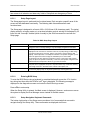
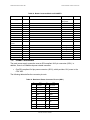
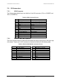
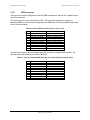
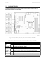
The following table details the pin-out definition of the VGA connector (J7A1 on S1200BTL and
J6A1 on S1200BTS):
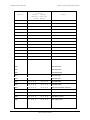
Table 28. VGA Connector Pin-out
Pin
1
2
3
4
5
6
7
8
9
10
11
12
13
14
15
7.5.2
Signal Name
V_IO_R_CONN
V_IO_G_CONN
V_IO_B_CONN
TP_VID_CONN_B4
GND
GND
GND
GND
TP_VID_CONN_B9
GND
TP_VID_CONN_B11
V_IO_DDCDAT
V_IO_HSYNC_CONN
V_IO_VSYNC_CONN
V_IO_DDCCLK
Description
Red (analog color signal R)
Green (analog color signal G)
Blue (analog color signal B)
No connection
Ground
Ground
Ground
Ground
No connection
Ground
No connection
DDCDAT
HSYNC (horizontal sync)
VSYNC (vertical sync)
DDCCLK
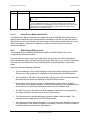
Rear NIC and USB connector
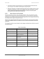
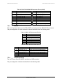
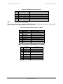
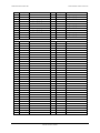
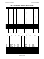
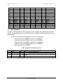
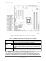
The server board provides two stacked RJ-45/2xUSB connectors side-by-side on the back edge
of the board. The pin-out for NIC connectors is identical and defined in the following table:
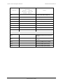
Table 29. RJ-45 10/100/1000 NIC Connector Pin-out
Pin
1
3
5
7
9
11
13
15
17
19
21
Signal Name
P5V_USB_PWR75
USB_PCH_11_FB_DP
P5V_USB_PWR75
USB_PCH_10_FB_DP
P1V9_LAN2_R
NIC2_MDIN<0>
NIC2_MDIN<1>
NIC2_MDIN<2>
NIC2_MDIN<3>
LED_NIC2_1
LED_NIC2_LINK100_R_0
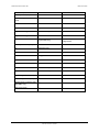
Pin
2
4
6
8
10
12
14
16
18
20
22
96
Signal Name
USB_PCH_11_FB_DN
GND
USB_PCH_10_FB_DN
GND
NIC2_MDIP<0>
NIC2_MDIP<1>
NIC2_MDIP<2>
NIC2_MDIP<3>
GND
P3V3_AUX
LED_NIC2_LINK1000_2
Revision 1.0
Intel order number G13326-003