1
DellTM PowerEdgeTM 3250 (SR870BH2)
Systems Product Guide
Model Code: SVS
Disclaimer
Information in this document is provided in connection with Intel® products. No license, express or implied, by estoppel or
otherwise, to any intellectual property rights is granted by this document. Except as provided in Intel’s Terms and Conditions
of Sale for such products, Intel assumes no liability whatsoever, and Intel disclaims any express or implied warranty, relating
to sale and/or use of Intel products including liability or warranties relating to fitness for a particular purpose, merchantability,
or infringement of any patent, copyright or other intellectual property right. Intel products are not intended for use in medical,
life saving, or life sustaining applications. Intel may make changes to specifications and product descriptions at any time,
without notice.
Server System SR870BH2 may contain design defects or errors known as errata which may cause the product to deviate
from published specifications. Current characterized errata are available on request.
Contact your local Intel sales office or your distributor to obtain the latest specifications and before placing your product
order.
Copies of documents which have an ordering number and are referenced in this document, or other Intel literature, may be
obtained from Intel Corporation by going to the World Wide Web site at: http://www.intel.com/ or by calling
1-800-548-4725.
Intel, Pentium and Itanium are registered trademarks of Intel Corporation or its subsidiaries in the United States and other
countries. Dell and PowerEdge are trademarks of Dell Computer Corporation.
* Other names and brands may be claimed as the property of others.
Copyright © 2003, Intel Corporation. All rights reserved.
2
Important Safety Information
Important Safety Instructions
Read all caution and safety statements in this document before performing any of the instructions.
See Intel Server Boards and Server Chassis Safety Information on the Resource CD and/or at
http://support.intel.com/support/motherboards/server/safecert.htm.
Wichtige Sicherheitshinweise
Lesen Sie zunächst sämtliche Warn- und Sicherheitshinweise in diesem Dokument, bevor Sie eine
der Anweisungen ausführen. Beachten Sie hierzu auch die Sicherheitshinweise zu IntelServerplatinen und -Servergehäusen auf der Ressourcen-CD oder unter
http://support.intel.com/support/motherboards/server/safecert.htm.
重要安全指导
在执行任何指令之前,请阅读本文档中的所有注意事项及安全声明。参见 Resource
CD(资源光盘) 和/或 http://support.intel.com/support/motherboards/server/safecert.htm 上的
Intel Server Boards and Server Chassis Safety Information(《Intel
服务器主板与服务器机箱安全信息》)。
Important Safety InstructionsConsignes de sécurité
Lisez attention toutes les consignes de sécurité et les mises en garde indiquées dans ce document
avant de suivre toute instruction. Consultez Intel Server Boards and Server Chassis Safety
Information sur le CD Resource CD ou bien rendez-vous sur le site
http://support.intel.com/support/motherboards/server/safecert.htm.
Instrucciones de seguridad importantes
Lea todas las declaraciones de seguridad y precaución de este documento antes de realizar
cualquiera de las instrucciones. Vea Intel Server Boards and Server Chassis Safety Information en
el CD Resource y/o en http://support.intel.com/support/motherboards/server/safecert.htm.
3
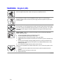
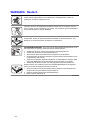
WARNING
Overcurrent protection: The server is designed for an AC line voltage
source with up to 20 amperes of overcurrent protection. If the power
system for the equipment rack is installed on a branch circuit with more
than 20 amperes of protection, you must provide supplemental
protection for the server.
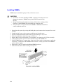
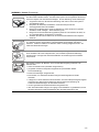
CAUTION
Temperature: The range of temperatures in which the server operates when
installed in an equipment rack, must not go below 10 °C (50 °F) or rise above
35 °C (95 °F). Extreme fluctuations in temperature can cause a variety of
problems in your server.
Ventilation: The equipment rack must provide sufficient airflow to the front
of the server to maintain proper cooling. The rack must also include
ventilation sufficient to exhaust a maximum of 700 W (2500 BTU/hr) for
each server. The rack selected and the ventilation provided must be suitable
to the environment in which the server will be used.
4
Regulatory and Certification Information
Product Regulatory Compliance
The Server System SR870BH2 complies with the following safety and electromagnetic
compatibility (EMC) regulations.
Product Safety Compliance
•
•
•
•
•
•
•
•
UL60950 - CSA 950 (US/Canada)
GB4943 – CNCA (China)
EN 60 950 (European Union)
IEC60 950 (International)
CE – Low Voltage Directive (73/23/EEC) (European Union)
EMKO-TSE (74-SEC) 207/94 (Nordics)
GOST R 50377-92 (Russia)
IRAM (Argentina)
Product EMC Compliance
•
•
•
•
•
•
•
•
•
•
•
•
•
•
•
FCC /ICES-003 - Class A Emissions (USA/Canada) Verification
GB9254 – Class A Emissions (CNCA China)
GB17625 – Harmonics (CNCA China)
CISPR 22 - Class A Emissions (International)
EN55022 - Class A Emissions (CENELEC Europe)
EN55024 - Immunity (CENELEC Europe)
EN61000-3-2 - Harmonics (CENELEC Europe)
EN61000-3-3 - Voltage Flicker (CENELEC Europe)
CE – EMC Directive 89/336/EEC (CENELEC Europe)
VCCI - Class A Emissions (Japan)
AS/NZS 3548 - Class A Emissions (Australia / New Zealand)
BSMI CNS13438 - Class A Emissions (Taiwan)
GOST R 29216-91 - Class A Emissions (Russia)
GOST R 50628-95 - Immunity (Russia)
RRL, MIC Notice No. 1997-41 (EMC) & 1997-42 (EMI) (Korea)
Regulatory and Certification Information
5
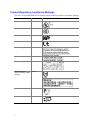
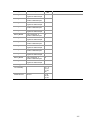
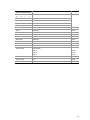
Product Regulatory Compliance Markings
The Server System SR870BH2 may be marked with the following regulatory compliance markings.
Regulatory Compliance
Country
cULus Listing Marks
USA/Canada
CCC Mark
China
GS Mark
Germany
CE Mark
Europe
FCC Marking (Class A)
USA
EMC Marking (Class A)
Canada
VCCI Marking (Class A)
Japan
BSMI Registration
Number / Marking & EMC
Warning
Taiwan
GOST R Marking
Russia
RRL MIC Mark
Korea
6
Marking
Electromagnetic Compatibility Notices
FCC Verification Statement (USA)
®
Intel Server System SR870BH2
This device complies with Part 15 of the FCC Rules. Operation is subject to the following two
conditions: (1) This device may not cause harmful interference, and (2) this device must accept any
interference received, including interference that may cause undesired operation.
Intel Corporation
5200 N.E. Elam Young Parkway
Hillsboro, OR 97124-6497
Phone: 1-800-628-8686
This equipment has been tested and found to comply with the limits for a Class A digital device,
pursuant to Part 15 of the FCC Rules. These limits are designed to provide reasonable protection
against harmful interference in a residential installation. This equipment generates, uses, and can
radiate radio frequency energy and, if not installed and used in accordance with the instructions,
may cause harmful interference to radio communications. However, there is no guarantee that
interference will not occur in a particular installation. If this equipment does cause harmful
interference to radio or television reception, which can be determined by turning the equipment off
and on, you are encouraged to try to correct the interference by one or more of the following
measures:
• Reorient or relocate the receiving antenna.
• Increase the separation between the equipment and the receiver.
• Connect the equipment into an outlet on a circuit different from that to which the receiver is
connected.
• Consult the dealer or an experienced radio/TV technician for help.
Any changes or modifications not expressly approved by the grantee of this device could void your
authority to operate the equipment. The customer is responsible for ensuring compliance of the
modified product.
Only peripherals (computer input/output devices, terminals, printers, etc.) that comply with FCC
Class A or B limits may be attached to this computer product. Operation with noncompliant
peripherals is likely to result in interference to radio and TV reception.
All cables used to connect to peripherals must be shielded and grounded. Operation with cables,
connected to peripherals that are not shielded and grounded may result in interference to radio and
TV reception.
Regulatory and Certification Information
7
ICES-003 (Canada)
Cet appareil numérique respecte les limites bruits radioélectriques applicables aux appareils
numériques de Classe Aprescrites dans la norme sur le matériel brouilleur: “Appareils
Numériques”, NMB-003 édictée par le Ministre Canadian des Communications.
English translation of the notice above:
This digital apparatus does not exceed the Class A limits for radio noise emissions from digital
apparatus set out in the interference-causing equipment standard entitled “Digital Apparatus,”
ICES-003 of the Canadian Department of Communications.
Europe (CE Declaration of Conformity)
This product has been tested in accordance too, and complies with the Low Voltage Directive
(73/23/EEC) and EMC Directive (89/336/EEC). The product has been marked with the CE Mark
to illustrate its compliance.
VCCI (Japan)
English translation of the notice above:
This is a Class A product based on the standard of the Voluntary Control Council for Interference
(VCCI) from Information Technology Equipment. If this is used near a radio or television receiver
in a domestic environment, it may cause radio interference. Install and use the equipment
according to the instruction manual.
BSMI (Taiwan)
The BSMI Registration Marking and Class A EMC warning is located on top cover of the product.
8
RRL (Korea)
Following is the RRL certification information for Korea.
English translation of the notice above:
1.
2.
3.
4.
5.
Type of Equipment (Model Name): SR870BH2
Certification No.: On RRL certificate. Obtain certificate from local Intel representative
Name of Certification Recipient: Intel Corporation
Date of Manufacturer: Refer to date code on product
Manufacturer/Nation: Intel Corporation/Refer to country of origin marked on product
Regulatory and Certification Information
9
Conventions
The following conventions are used in this manual:
WARNING
Warnings indicate conditions that, if not observed, can cause personal
injury.
CAUTION
Cautions warn you about how to prevent damage to hardware or loss of data.
NOTE
Notes call attention to important information.
10
Contents
Important Safety Information ............................................................................. 3
Regulatory and Certification Information ......................................................... 5
Product Regulatory Compliance ............................................................................................. 5
Product Safety Compliance............................................................................................ 5
Product EMC Compliance .............................................................................................. 5
Product Regulatory Compliance Markings ..................................................................... 6
Electromagnetic Compatibility Notices.................................................................................... 7
FCC Verification Statement (USA) ................................................................................. 7
ICES-003 (Canada)........................................................................................................ 8
Europe (CE Declaration of Conformity).......................................................................... 8
VCCI (Japan).................................................................................................................. 8
BSMI (Taiwan)................................................................................................................ 8
RRL (Korea) ................................................................................................................... 9
Conventions....................................................................................................... 10
Part 1: System Description and Configuration ............................................. 23
1 System Description...................................................................................... 23
External Chassis Features .................................................................................................... 25
Chassis Front ............................................................................................................... 25
Front Panel .................................................................................................... 26
Peripheral Bay ............................................................................................... 27
Power Bay 30
Chassis Rear................................................................................................................ 32
Internal Chassis Features ..................................................................................................... 33
Electronics Bay............................................................................................................. 33
Cooling Subsystem ...................................................................................................... 34
Power Subsystem ........................................................................................................ 38
Power Supply Modules.................................................................................. 38
Redundant AC Power Source Operation....................................................... 38
Processor Power Pods .................................................................................. 38
2 Board Set Description.................................................................................. 39
Main Board............................................................................................................................ 41
Processor Sockets ....................................................................................................... 42
Memory Subsystem...................................................................................................... 42
SCSI Controller ............................................................................................................ 43
Network Interface Controller......................................................................................... 43
Video Controller............................................................................................................ 44
IDE Controller............................................................................................................... 44
Baseboard Management Controller (BMC) .................................................................. 44
PCI Riser Board .................................................................................................................... 46
SCSI Backplane Board ......................................................................................................... 46
11
QLogic* GEM359* SCSI Hot-swap Controller.............................................................. 47
Peripheral Board ................................................................................................................... 48
Peripheral Board Functional Blocks ............................................................................. 48
Peripheral Interface ...................................................................................................... 48
Server Management.............................................................................................................. 49
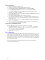
3 Configuration Software and Utilities .......................................................... 50
Utilities / Drivers on Resource CD......................................................................................... 50
Running Software Utilities Directly from the Resource CD .......................................... 50
Power-on Sequence and Power-on Self-Test (POST).......................................................... 50
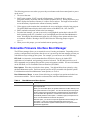
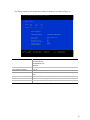
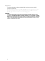
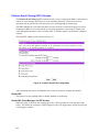
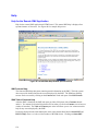
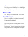
Extensible Firmware Interface Boot Manager ....................................................................... 51
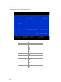
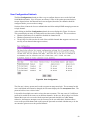
The Extensible Firmware Interface (EFI) Shell ..................................................................... 54
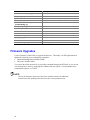
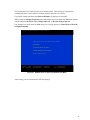
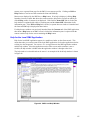
Firmware Upgrades............................................................................................................... 56
Running the Firmware Update Utility............................................................................ 57
BIOS Upgrades ..................................................................................................................... 59
BIOS Upgrade Procedure ............................................................................................ 60
CMOS Clear ................................................................................................................. 61
BIOS Recovery Mode................................................................................................... 62
FRUSDR Load Utility ............................................................................................................ 63
Running the FRUSDR Load Utility ............................................................................... 64
FRUSDR Load Utility Command-line Options.............................................................. 64
Command-line Precedence ........................................................................... 66
Displaying Usage Information........................................................................ 66
Displaying the FRU Area.............................................................................................. 67
Displaying the SDR Area.............................................................................................. 68
Checking the FRU Data Integrity.................................................................................. 69
Updating the SDR Non-Volatile Storage Area.............................................................. 69
Updating the FRU Non-Volatile Storage Area.............................................................. 69
Configuration File ......................................................................................................... 70
Compare Command ...................................................................................... 70
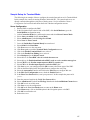
BIOS Setup ........................................................................................................................... 71
Starting Setup .............................................................................................................. 71
Recording Your Setup Settings .................................................................................... 71
Navigating Setup Utility Screens .................................................................................. 72
Setup Screens.............................................................................................................. 73
Main
73
Advanced 74
Security 75
System Management..................................................................................... 75
Exit
76
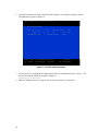
LSI Logic* SCSI Utility........................................................................................................... 77
System Maintenance Utility................................................................................................... 82
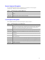
Remote Keyboard Navigation ...................................................................................... 83
Local Keyboard Navigation .......................................................................................... 83
About Box Information.................................................................................................. 84
Server Discovery .......................................................................................................... 85
Remote SMU Application ............................................................................................. 85
Local SMU Application ................................................................................................. 88
Running from CD........................................................................................... 88
12
Running from the System Partition................................................................ 88
Shut Down SMU Application ........................................................................................ 89
Server Management Configuration Task...................................................................... 89
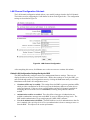
LAN Channel Configuration Sub-task............................................................ 90
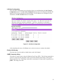
User Configuration Sub-task ......................................................................... 99
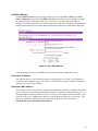
Platform Event Filtering (PEF) Sub-task...................................................... 102
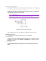
Serial/Modem Channel Configuration Sub-task .......................................... 110
Power Configuration Sub-task..................................................................... 121
SEL Viewer ................................................................................................................ 122
Viewing Events in the SEL .......................................................................... 123
Sorting the SEL ........................................................................................... 125
SDR Viewer................................................................................................................ 127
Viewing SDRs.............................................................................................. 128
FRU Viewer ................................................................................................................ 130
Viewing FRUs.............................................................................................. 131
Task Error Handling ................................................................................................... 133
Data Entry Errors......................................................................................... 133
Internal Errors For Which a View Can Be Generated.................................. 133
Data Corruption Errors that the SMU Application Can Handle .................... 133
Internal Errors For Which a View Cannot Be Generated............................. 133
Help
134
Help for the Remote SMU Application......................................................... 134
Help for the Local SMU Application............................................................. 135
EFI Platform Diagnostic Tests............................................................................................. 136
Starting the Application .............................................................................................. 136
Understanding the General User Interface................................................................. 137
Understanding Basic Testing ..................................................................................... 137
Enabling Tests For Execution .................................................................................... 137
Setting Test Options................................................................................................... 138
Interpreting Results .................................................................................................... 138
Help On Individual Tests ............................................................................................ 138
Viewing System Information....................................................................................... 138
Viewing the Test Log.................................................................................................. 139
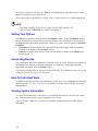
EFI Service Partition ........................................................................................................... 139
Service Partition Requirements.................................................................................. 139
Installing Service Partition Files ................................................................................. 139
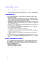
Installation Requirements........................................................................................... 140
Installing the Files....................................................................................................... 140
Booting from the Service Partition.............................................................................. 140
Locally
141
Console Redirection............................................................................................................ 141
Operation ................................................................................................................... 141
Keystroke Mappings................................................................................................... 142
Limitations .................................................................................................................. 144
Server Management Interface.................................................................................... 144
Sample Setup for Console Redirection ....................................................... 144
Terminal Mode .................................................................................................................... 145
Setup and Configuration............................................................................................. 146
Connection Mechanism ............................................................................... 146
13
Hardware Setup........................................................................................... 146
Configuration Using System Maintenance Utility (SMU) ............................. 146
Serial Channel Configuration....................................................................... 146
Sample Setup for Terminal Mode................................................................ 147
User Configuration....................................................................................... 148
Security Information ................................................................................................... 149
Terminal Mode Commands ........................................................................................ 149
Input Restrictions......................................................................................... 149
Hex-ASCII Command Format .................................................................................... 150
Text Command Format .............................................................................................. 151
Terminal Mode IPMI Message Bridging ..................................................................... 151
Shutting Down the Server ................................................................................................... 161
Part 2: Servicing the System......................................................................... 162
Warnings and Cautions....................................................................................................... 162
Before Top Cover or Module Removal....................................................................... 163
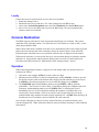
4 Working Inside the System ....................................................................... 163
Tools and Supplies Needed ................................................................................................ 163
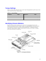
Torque Settings................................................................................................................... 165
Identifying Chassis Modules ............................................................................................... 165
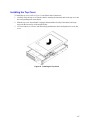
Removing and Installing the Top Cover .............................................................................. 166
Removing the Top Cover ........................................................................................... 166
Installing the Top Cover ............................................................................................. 167
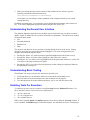
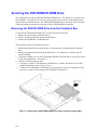
5 Hot-swapping System Components......................................................... 168
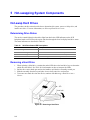
Hot-swap Hard Drives ......................................................................................................... 168
Determining Drive Status ........................................................................................... 168
Removing a Hard Drive .............................................................................................. 168
Mounting a Hard Drive into a Carrier.......................................................................... 169
Installing a Hard Drive ................................................................................................ 170
Hot-swap System Fans ....................................................................................................... 170
Determining Fan Failure............................................................................................. 171
Replacing a System Fan ............................................................................................ 171
Hot-swap Power Supplies ................................................................................................... 172
Determining Power Supply Status.............................................................................. 172
Power Module Removal and Replacement ................................................................ 173
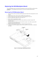
6 Servicing the Electronics Bay................................................................... 174
Adding or Replacing PCI Cards .......................................................................................... 174
Removing the PCI Riser Assembly ............................................................................ 174
Installing PCI Cards.................................................................................................... 176
Installing the PCI Riser Assembly .............................................................................. 176
Replacing the Battery.......................................................................................................... 177
7 Servicing the Main Board .......................................................................... 178
®
®
Working with Intel Itanium 2 Processors .......................................................................... 178
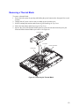
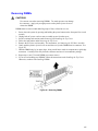
Replacing a Thermal Blank ................................................................................................. 178
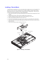
Removing a Thermal Blank ........................................................................................ 179
Installing a Thermal Blank .......................................................................................... 180
14
Replacing a Processor ........................................................................................................ 181
Removing a Power Pod.............................................................................................. 181
Removing a Processor ............................................................................................... 182
Installing a Processor ................................................................................................. 183
Installing a Power Pod................................................................................................ 183
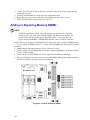
Adding or Replacing Memory DIMMs ................................................................................. 184
Removing DIMMs....................................................................................................... 185
Installing DIMMs......................................................................................................... 186
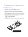
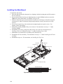
Replacing the Main Board................................................................................................... 187
Removing the Main Board.......................................................................................... 187
Installing the Main Board............................................................................................ 188
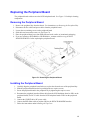
8 Servicing the Peripheral Bay..................................................................... 189
Removing and Installing the Peripheral Bay ....................................................................... 189
Removing the Peripheral Bay..................................................................................... 189
Installing the Peripheral Bay....................................................................................... 190
Replacing the Peripheral Board .......................................................................................... 191
Removing the Peripheral Board ................................................................................. 191
Installing the Peripheral Board ................................................................................... 191
Servicing the DVD-ROM/CD-ROM Drive ............................................................................ 192
Removing the DVD/CD-ROM Drive from the Peripheral Bay..................................... 192
Removing the DVD-ROM/CD-ROM Drive from the Drive Carrier .............................. 193
Installing the DVD-ROM/CD-ROM Drive.................................................................... 194
Replacing the SCSI Backplane Board ................................................................................ 195
Removing the SCSI Backplane Board ....................................................................... 195
Installing the SCSI Backplane Board ......................................................................... 196
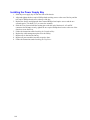
9 Servicing the Power Bay ........................................................................... 197
Removing the Power Supply Bay............................................................................... 197
Installing the Power Supply Bay................................................................................. 198
10 Technical Reference .................................................................................. 199
System Interconnection....................................................................................................... 200
User-Accessible Interconnects............................................................................................ 201
Serial Port .................................................................................................................. 201
Video Port .................................................................................................................. 202
Universal Serial Bus (USB) Interface ......................................................................... 203
Ethernet Connector .................................................................................................... 204
Ultra320 SCA-2 HDD Connector................................................................................ 206
External Ultra320 SCSI Connector............................................................................. 207
AC Power Input .......................................................................................................... 208
Jumper Information ............................................................................................................. 209
Changing Jumper Settings ......................................................................................... 209
Configuring Main Board Jumpers............................................................................... 209
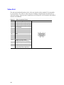
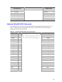
POST Error Codes and Messages ................................................................. 211
North and South Port 80/81 Cards...................................................................................... 211
POST Codes ....................................................................................................................... 211
POST Codes Module Map...................................................................................... 211
Specific POST Code Modules.................................................................................... 214
15
SAL-A Module ............................................................................................. 214
SAL-B Module ............................................................................................. 216
SAL-F Module.............................................................................................. 219
IA-32 Module ............................................................................................... 220
Recovery Port 80 Codes .......................................................................... 224
POST Error Codes and Messages ......................................................... 225
POST Beep Codes..................................................................................................... 227
Memory Test Failure ........................................................................................................... 228
Recovery Beep Codes ............................................................................................... 228
Safety Warnings .............................................................................................. 229
WARNING: English (US).................................................................................................... 230
AVERTISSEMENT: Français ............................................................................................. 232
WARNUNG: Deutsch ......................................................................................................... 234
AVVERTENZA: Italiano...................................................................................................... 236
ADVERTENCIAS: Español ................................................................................................ 238
16
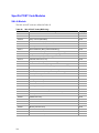
Figures
Figure 1. Server System Front................................................................................................... 23
Figure 2. Server System Front with Bezel Installed ................................................................... 25
Figure 3. Server System Front with Bezel Removed ................................................................. 25
Figure 4. Front Panel Controls, Indicators, and Connectors ...................................................... 27
Figure 5. Peripheral Bay ............................................................................................................ 27
Figure 6. Hard Drive Carrier....................................................................................................... 28
Figure 7. DVD-ROM / CD-ROM Drive Installation ..................................................................... 29
Figure 8. Power Bay .................................................................................................................. 30
Figure 9. AC Power Status LEDs............................................................................................... 31
Figure 10. Chassis Rear Features ............................................................................................. 32
Figure 11. Electronics Bay ......................................................................................................... 33
Figure 12. Electronics Bay (subassembly removed).................................................................. 34
Figure 13. Power Bay (removed from chassis).......................................................................... 35
Figure 14. Cooling Subsystem Layout ....................................................................................... 36
Figure 15. System Fan Status LED ........................................................................................... 37
Figure 16. Main Board Layout.................................................................................................... 40
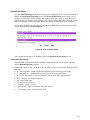
Figure 17. Location of Memory DIMMS ..................................................................................... 42
Figure 18. LSI SCSI Utility Main Menu ...................................................................................... 78
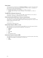
Figure 19. Adapter Properties.................................................................................................... 79
Figure 20. Device Properties ..................................................................................................... 80
Figure 21. Adapter and / or Device Properties Exit Menu.......................................................... 81
Figure 22. SMU Application About Box...................................................................................... 84
Figure 23. SMU Application About Box (Advanced button selected) ......................................... 85
Figure 24. Service Partition Utilities ........................................................................................... 86
Figure 25. SMU Home ............................................................................................................... 87
Figure 26. LAN Channel Configuration ...................................................................................... 90
Figure 27. LAN Alert Configuration ............................................................................................ 93
Figure 28. New / Edit LAN Alert ................................................................................................. 95
Figure 29. Serial Over LAN Configuration ................................................................................. 97
17
Figure 30. User Configuration.................................................................................................... 99
Figure 31. Edit User Configuration........................................................................................... 100
Figure 32. Platform Event Filter Configuration......................................................................... 102
Figure 33. Event Filter Settings................................................................................................ 104
Figure 34. Edit Event Filter Settings ........................................................................................ 105
Figure 35. Alert Policy Configuration ....................................................................................... 107
Figure 36. Edit Alert Policy Entry ............................................................................................. 108
Figure 37. Serial / Modem Channel Configuration ................................................................... 110
Figure 38. Modem Mode Configuration ................................................................................... 112
Figure 39. Destination Dial Settings......................................................................................... 114
Figure 40. New / Edit Dial String.............................................................................................. 115
Figure 41. Page Destination Configuration .............................................................................. 116
Figure 42. Edit Page Destination ............................................................................................. 117
Figure 43. Terminal Mode Configuration ................................................................................. 119
Figure 44. Power Configuration ............................................................................................... 121
Figure 45. SEL Viewer, Hex Display Mode.............................................................................. 123
Figure 46. SDR Viewer ............................................................................................................ 128
Figure 47. FRU Viewer ............................................................................................................ 131
Figure 48. Remote SMU Help Window (browser based) ......................................................... 134
Figure 49. SMU Local Help Window ........................................................................................ 135
Figure 50. Tools and Supplies Needed.................................................................................... 163
Figure 51. Locating System Modules....................................................................................... 165
Figure 52. Removing the Top Cover........................................................................................ 166
Figure 53. Installing the Top Cover.......................................................................................... 167
Figure 54. Removing a Hard Drive .......................................................................................... 168
Figure 55. Removing Air Baffle from Hard Drive Carrier.......................................................... 169
Figure 56. Attaching the Hard Drive to the Carrier................................................................... 170
Figure 57. System Fan Location and Removal ........................................................................ 171
Figure 58. Removing and Replacing Power Module................................................................ 173
Figure 59. Removing PCI Riser Assembly............................................................................... 175
18
Figure 60. Removing the Thermal Blank ................................................................................. 179
Figure 61. Installing a Thermal Blank ...................................................................................... 180
Figure 62. Removing Power Pod and Processor ..................................................................... 182
Figure 63. Installing a Processor and Power Pod.................................................................... 183
Figure 64. Location of Memory DIMMS ................................................................................... 184
Figure 65. Removing DIMMs ................................................................................................... 185
Figure 66. Installing DIMMs ..................................................................................................... 186
Figure 67. Removing the Main Board ...................................................................................... 187
Figure 68. Installing the Main Board ........................................................................................ 188
Figure 69. Removing the Peripheral Bay ................................................................................. 190
Figure 70. Removing the Peripheral Board.............................................................................. 191
Figure 71. Removing the DVD-ROM/CD-ROM Drive Carrier from the Peripheral Bay............ 192
Figure 72. Removing the DVD/CD-ROM Drive from the Carrier.............................................. 193
Figure 73. Assembling the DVD/CD-ROM Drive and Carrier................................................... 194
Figure 74. Removing the SCSI Backplane Board.................................................................... 195
Figure 75. Removing the Power Supply Bay ........................................................................... 197
Figure 76. Interconnect Block Diagram.................................................................................... 199
Figure 77. AC Power Input Connector ..................................................................................... 208
Figure 78. Main Board Layout.................................................................................................. 210
19
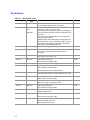
Tables
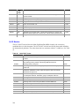
Table 1.
Physical Specifications .................................................................................. 23
Table 2.
Feature Summary.......................................................................................... 24
Table 3.
SCSI Hard Drive LED Details ........................................................................ 28
Table 4.
Boot Maintenance Menu Options .................................................................. 51
Table 5.
EFI Shell Commands..................................................................................... 54
Table 6.
Firmware Update Utility Command-line Options and Parameters ................. 57
Table 7.
IFlash64 Utility Command-line Options and Parameters............................... 60
Table 8.
Setup Screen Navigation............................................................................... 72
Table 9.
BIOS Setup Main Screen Menu Items........................................................... 73
Table 10.
Processor Settings Submenu Items .............................................................. 73
Table 11.
BIOS Setup Advanced Screen Menu Items .................................................. 74
Table 12.
BIOS Setup Security Screen Menu Items ..................................................... 75
Table 13.
BIOS Setup System Management Screen Menu Items ................................ 75
Table 14.
Setup Console Redirection Sub Menu Items................................................. 76
Table 15.
BIOS Setup Exit Screen Menu Items ............................................................ 76
Table 16.
Keyboard Support for Remote SMU Client.................................................... 83
Table 17.
Keyboard Support for Local SMU Client........................................................ 83
Table 18.
Common Buttons for Configuration Management Sub-tasks ........................ 89
Table 19.
SEL Sort Order Definitions .......................................................................... 125
Table 20.
SDR Type Name Format ............................................................................. 129
Table 21.
Non-ASCII Key Mappings............................................................................ 142
Table 22.
ASCII Key Mappings ................................................................................... 143
Table 23.
Terminal Mode Request to BMC ................................................................. 150
Table 24.
Terminal Mode Request from BMC ............................................................. 150
Table 25.
Supported BMC Combinations for IPMI Message Bridging......................... 151
Table 26.
Terminal Mode Text Commands ................................................................. 152
Table 27.
Boot Option Parameters .............................................................................. 156
Table 28.
Terminal Mode Configuration ...................................................................... 160
20
Table 29.
Torque Settings ........................................................................................... 165
Table 30.
SCSI Drive Status LED Descriptions........................................................... 168
Table 31.
Power Supply LEDs..................................................................................... 172
Table 32.
PCI Slot Information .................................................................................... 176
Table 33.
Cable and Connector Descriptions.............................................................. 200
Table 34.
Com Connector Pinout ................................................................................ 201
Table 35.
Video Connector Pinout............................................................................... 202
Table 36.
USB Connector Pinout ................................................................................ 203
Table 37.
Ethernet Connector Pinout .......................................................................... 204
Table 38.
Ultra320 SCA-2 Connector Pinout............................................................... 206
Table 39.
External Ultra320 SCSI Connector Pinout................................................... 207
Table 40.
Main Board Jumpers ................................................................................... 209
Table 41.
General POST Code Module Numbers for Itanium®-based Platforms ....... 212
Table 42.
SAL-A POST Codes (BSP Only) ................................................................. 214
Table 43.
SAL-B POST Codes .................................................................................... 216
Table 44.
SAL-F POST Codes .................................................................................... 219
Table 45.
IA-32 POST Codes...................................................................................... 220
Table 46.
ACPI POST Codes ...................................................................................... 223
Table 47.
SAL Runtime POST Codes ......................................................................... 223
Table 48.
Recovery POST Codes ............................................................................... 224
Table 49.
POST Error Messages and Codes .............................................................. 225
Table 50.
Error Beep Codes........................................................................................ 227
Table 51.
POST Memory Beep Error Codes – Debug Port Encoding List .................. 227
Table 52.
Recovery Mode Beep Codes....................................................................... 228
21
22
Part 1: System Description and Configuration
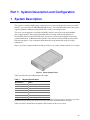
1 System Description
®
The system is a compact, high-density, rack mount server system with support for one to two Intel
®
Itanium 2 processors and 16-GB DDR SDRAM memory. The scaleable architecture of the system
supports Symmetric Multiprocessing (SMP) and a variety of operating systems.
The server system supports several high availability features, such as hot-swap and redundant
power supply modules, hot-swap and redundant fans for cooling, and hot-swap hard drives.
Serviceability features include LED indicators for system, reset, hard drive and LAN status and
system identification. Additional features include video connector and dual USB ports accessible
from the front panel. Color-coded parts differentiate hot-swap and non-hot-swap serviceable
components.
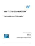
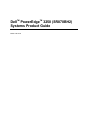
Figure 1 provides a diagram of the front and top of the server system, with the chassis cover in place.
Figure 1. Server System Front
Table 2 provides the system dimensions and weight.
Table 1.
Physical Specifications
Specification
Value
Height
3.4 inches (87 mm)
Width
17.7 inches (449 mm)
Depth
29.4 inches (747 mm)
Front clearance
3 inches (76 mm)
Side clearance
1 inch (25 mm)
Rear clearance
6 inches (152 mm)
Weight (note 1)
65 lbs (30 kg)
Note 1. The system weight listed above is an estimate for a fully configured system and will vary depending on the number
of peripheral devices and add-in cards as well as the number of processors and DIMMs installed in the system.
Table 2 provides a list and brief description of the features of the server system.
23
Table 2.
Feature Summary
Feature
Description
Compact, high-density
system
Rack-mount server with a height of 2U (3 1/2 inches) and a depth of 28 inches
Configuration flexibility
• 1-2 way capability in low profile and cost effective packaging
• Stand-alone system including external I/O slots/disk expansion as needs
grow
• Intel Itanium 2 processor support
• 16-GB Double Data Rate (DDR) Synchronous Dynamic Random Access
Memory (SDRAM) memory support
Serviceability
• Front access to hot-swap hard drives
• Hot-swap fans
• Front access to hot-swap power supplies
• Dockable power to main board
• System power and reset status LEDs
• System ID switch on front panel and LEDs on front and back
• Color-coded parts to identify hot-swap and non-hot-swap serviceable
components
Availability
• Three PCI-X slots
• Three hot-swap 350-W power supplies in a redundant (2+1) configuration
• Dual redundant power cords (1+1) when three power supplies are present
• Six hot-swap system fans in a redundant (5+1) configuration
• Two hot-swap 1-inch Ultra320 SCSI hard drives
Manageability
• Remote management
• Emergency Management Port (EMP)
• Intelligent Platform Management Interface (IPMI) 1.5 compliant
• Wired For Management (WfM) 2.0 compliant
• Remote diagnostics support
Upgradeability and
investment protection
• Supports Intel Itanium 2 processors
• Field upgradeable to next generation (Montecito) processor family
• Multi-generational chassis
System-level scalability
• Up to 16-GB DDR SDRAM (using 2-GB DIMMs)
• One to two Intel Itanium 2 processors
• External I/O (3 slots) / disk expansion
• External SCSI connector
Front panel
24
• System Power switch and LED
• System Status LED
• System Reset switch
• Hard Drive Fault LED
• System Diagnostic Interrupt (SDINT)
switch
• LAN1 & LAN2 Status LEDs
• System ID switch and LED
• Dual USB 1.1 Ports
• Video Connector
External Chassis Features
System controls and indicators are located in several places on the chassis as follows:
• Chassis front:
•
Front panel: Front panel switches and LEDs
Peripheral bay: Hard drive LEDs
Power bay: Power Module LEDs and Power Supply LEDs
Chassis rear panel: System ID LEDs and LAN port LEDs
Each of these areas is discussed below.
Chassis Front
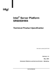
The following figure shows the front of the chassis with the snap-on bezel in place. The bezel must
be removed to access the front panel switches, power supplies, SCSI drives and DVD-CDRW
devices.
Figure 2. Server System Front with Bezel Installed
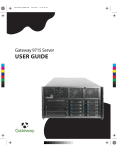
Figure 3. Server System Front with Bezel Removed
25
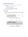
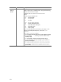
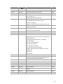
Front Panel
The front panel (Figure 4) is located at the right side of the server system, at the front of the chassis.
The front control panel displays status lights for system status, hard drives, and power supplies.
Callout
Control, Connector, Indicator
Description
A
System Power switch & LED
Toggles system power
LED
State
ACPI
Off
Power off
No
On
Power on
No
Off
S5
Yes
On
S0
Yes
B
System Reset switch
Resets the system.
C
SDINT (System Diagnostic
Interrupt) switch
Asserts SDINT
D
System ID switch and LED (Blue)
System identification switch and light
E
System Status/Fault LED
(Green/Amber)
Indicates system status.
26
LED
State
Description
Off
Not ready
Post err/NMI Ev/CPU missing
Green,
solid
Ready
No Alarms
Green,
blinking
Ready – Degraded
CPU Fault, DIMM killed
Amber,
solid
Critical Alarm
Critical of Pwr Flt, Fan, Voltage,
and Temperature failures.
Amber,
blinking
Non-Critical Alarm
Non-Critical of redundant Pwr
Flt, redundant Fan, Voltage,
and Temperature failures.
F
Hard Drive Fault LED (Amber)
Indicates hard drive subsystem fault status.
LED
State
Description
Off
Drive Missing
Slot Empty, Online, Prepare for
removal.
On
Inactive
Drive Failed
Blinking
G, H
LAN1, LAN2 Status LEDs
(Green)
Drive Identity, Rebuild,
Predictive Fail, Rebuild
Interrupt or Rebuild on empty
slot.
Indicates LAN activity status.
LED
State
Off
Idle
Description
On
Inactive
No Access
Blinking
Active
Access
I
Video connector
Video port, standard VGA compatible, 15-pin connector
J
USB3 connector
USB port 3, 4-pin connector
K
USB4 connector
USB port 2, 4-pin connector
Figure 4. Front Panel Controls, Indicators, and Connectors
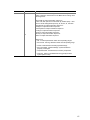
Peripheral Bay
The peripheral bay (Figure 5) supports up to two 1-inch hot-swap Ultra320 SCSI hard drives and
one ½-inch IDE DVD/CD-ROM drive.
The peripheral bay supports Low Voltage Differential (LVD) SCSI disk drives only. Single-Ended
(SE) SCSI devices are not supported in the peripheral bay, however SE device support is available
via the secondary external SCSI channel located at the rear of the chassis.
Hard Drives
DVD/CD Drive
TP00296
Figure 5. Peripheral Bay
27
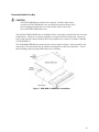
Hot-swap Hard Drive Carrier
The hot-swap hard drive carrier accepts 15,000-RPM and slower Ultra320 SCSI technology SCAtype hard drives. The peripheral bay supports Low Voltage Differential (LVD) SCSI disk drives
only. Single-Ended (SE) SCSI devices are not supported in the peripheral bay. SE drives are only
®
supported on the external SCSI connector. Refer to the Intel Server System SR870BH2 Hardware
and Operating System Validation List for details on tested devices. Contact your Intel
representative to obtain this list.
Hard drive carriers that accommodate 3.5-inch by 1.0-inch SCSI disk drives are required as part of
the hot-swap implementation. The disk drive is attached to the carrier with four fasteners, and is
retained in the chassis by a locking handle. Figure 6 shows a hard drive carrier that has been
removed from the peripheral bay. The drive is accessed by pressing the latch to release the drive
carrier door, then pulling out on the door.
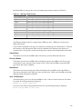
The SCSI backplane board contains a dual-color LED for each hard drive. The LED can be seen at
the right edge of the carrier, as shown in the figure. The LED displays the drive status, as described
in Table 3.
Figure 6. Hard Drive Carrier
Table 3.
SCSI Hard Drive LED Details
Feature
Description
Green, flashing
Indicates the hard drive is active
Yellow/Green flashing
Indicates a hard drive fault and hard drive is powered
Yellow/Blank flashing
Indicates a hard drive fault and hard drive is not powered
Not illuminated
Indicates no hard drive is installed in the bay
28
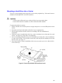
Removable Media Drive Bay
CAUTION
The DVD/CD-ROM drive cannot be hot-swapped. In order to add, remove
or replace a DVD/CD-ROM drive, the system must be powered down, power
sources unplugged and the top cover of the chassis must be removed to
access the DVD/CD-ROM drive area.
The slim-line DVD/CD-ROM drive is installed in a drive carrier that is inserted form the rear of the
peripheral bay. This device is not hot-swappable; you must switch off system power, remove all
power cords, open the chassis and then remove the peripheral bay to remove or install a CD-ROM
or DVD-ROM drive.
The CD-ROM/DVD-ROM drive snaps into the carrier as shown in Figure 7 and is secured by four
raised points. The raised points line up with the mounting holes on the sides of the drive. Two of
these mounting points are spring loaded and two are stationary.
Figure 7. DVD-ROM / CD-ROM Drive Installation
29
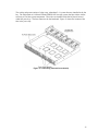
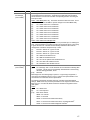
Power Bay
The power bay (Figure 8) is located in the lower front of the system. Redundant power status LED
indicators are in the left portion of the power bay and three hot-swap power supply modules dock
into the three bays on the right.
Power Status LEDs
Power Supply Modules
TP00295
Figure 8. Power Bay
The power subsystem can be configured as follows:
• Three power supply modules installed, (2+1) redundancy
• Two power supply modules installed, non-redundant
NOTE
The power supply modules must be populated from right to left. The left
power supply module is optional in a non-redundant configuration. If no
module is installed in the left slot, a filler panel is required for proper system
cooling.
Two power supply modules are capable of handling the worst-case power requirements for a fully
configured server system. This includes two Intel Itanium 2 processors, 16 GB of memory, three
PCI add-in cards, two hard drives, and a DVD-ROM / CD-ROM drive.
When the system is configured with three power supply modules, the hot-swap feature allows you
to replace a failed power supply module while the system is running.
The power subsystem receives AC power through two power cords. When three power supply
modules and two power cords are installed, the system supports (1+1) power cord redundancy.
This feature allows the system to be powered by two separate AC sources. In this configuration,
the system will continue to function without interruption if one of the AC sources fails.
30
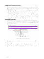
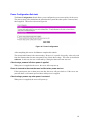
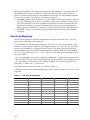
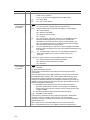
The AC power status LEDs in the power supply module provide information on the status of the
power sources. The LEDs are shown Figure 9. The table below the figure defines the possible
LED states.
LED
Description
AC1 (green)
On - AC input #1 available.
Off - AC input #1 unavailable or below voltage threshold to power up the system.
AC2 (green)
On - AC input #2 available.
Off - AC input #2 unavailable or below voltage threshold to power up the system.
ACR (green)
On - redundant feature is available.
Off - redundant feature is not available
Figure 9. AC Power Status LEDs
The power redundancy feature requires that each of the following conditions be present.
• AC input #1 available
• AC input #2 available
• Power good signals asserted from all three power supply modules
• TS-OK signal is asserted
31
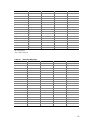
Chassis Rear
Figure 10 shows the rear of the system.
Callout
Description
A
PCI Slots
Slot 1
100-MHz, 64-bit PCI-X slot, full length
Slot 2
100-MHz, 64-bit PCI-X slot, full length
Slot 3
133-MHz, 64-bit PCI-X slot, full length
B
AC input power connectors (two)
C
External SCSI connector1
D
System ID switch
E
System ID LED (blue)
F
Two LAN ports, RJ45 connector (LAN1 on bottom, LAN2 on top)
LAN port LEDs:
Status LED (Green)
On – Ethernet link is detected
Off – no Ethernet connection
Blinking – Ethernet link is active
Speed LED
(Green/Amber)
Off – 10 Mbps
Green On – 100 Mbps
Amber On – 1000 Mbps
2
G
Serial port , RJ45 connector
H
Two USB 1.1 ports, 4-pin connectors (USB0 on bottom, USB1 on top)
I
Video port, standard VGA compatible, 15-pin connector
Notes:
1.
External SCSI bus supports both LVDS and SE signals via the external SCSI connector.
2.
EMP access is provided via shared serial port.
Figure 10. Chassis Rear Features
32
Internal Chassis Features
WARNING
Only qualified technical personnel should access any internal system
component. Some exposed circuits exceed 240 VA and may cause injury
if accidentally contacted.
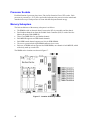
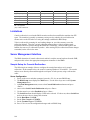
Electronics Bay
The electronics bay, shown in Figures 11 and 12, consists of the following:
• Main board
• PCI riser board
• Two processor locations and two power pod locations
• Eight DIMM slots
• Air duct for the processor area
• PCI riser bracket to support PCI riser board and PCI cards
• Connectors, switches and LEDs at the rear of the chassis (see Figure 10)
Figure 11. Electronics Bay
33
Figure 12. Electronics Bay (subassembly removed)
Cooling Subsystem
CAUTIONS
The chassis top cover must be installed and closed for proper system cooling.
Cooling components must be hot-swapped within a limited time period. This
time period applies only to the time that the cooling component is removed
from the system, not from the time of failure.
34
The cooling subsystem consists of a hot-swap, redundant (5+1) system fan array installed in the fan
bay. The single bank of six Delta* FFB0612EHE-S18Z hot-swap system fans provide the airflow
necessary to cool the system components. These fans are installed in the fan bay that is located
within the power bay. The fans connect to the fan baseboard. Figure 13 shows the location of the
fans in the power bay.
Figure 13. Power Bay (removed from chassis)
35
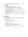
Figure 14 shows the cooling subsystem layout with the airflow direction indicated.
Figure 14. Cooling Subsystem Layout
The server system supports only a fully populated system fan configuration. However, the system
will continue to meet thermal specifications with either a system fan or a power supply failure. The
power supply redundancy feature applies to systems with three power modules installed.
If a fan fails, system cooling is maintained and the system continues to operate while the failed fan
is being hot-swapped. All system fans have tachometer output, internal speed control, and external
Pulse Width Modulation (PWM) speed control.
A failure is detected when the RPM of a fan falls below a predetermined minimum threshold
(Approx. 5000 RPM). If a system fan falls below this threshold, all fans will be boosted to operate
at a higher speed (Approx. 8500 RPM)
The fans will also be boosted to the higher speed if a power supply fails for any reason (including
loss of AC power). The fans will not be boosted if the Redundant (ACR) power supply fails. If the
redundant power supply fails, the system fans will not be affected.
When boosted, all fans remain at high speed until the failed fan or power supply is replaced. When
a fan replacement is detected by a change in state of the fan presence signal. After a failed fan is
replaced, the fans return to the lower speed and fan failure monitoring at the lower speed levels is
reactivated.
When a power supply fails and is replaced, the replacement is detected by server management.
36
NOTES
Do not attempt to operate this system with less than a fully populated, six
system fan configuration.
To maintain adequate cooling for system components, the swap process must
be completed in two-minutes. This period only applies to the time that the
fan or power supply is removed from the system, not from the time of failure.
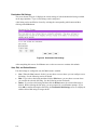
A system fan failure is indicated by the corresponding fan LED and by the Cooling Fault LED on
the front panel. The system fan LEDs are shown in Figure 15. The LED is amber and turns on if a
system fan failure occurs. These LEDs can be seen only when the top cover is removed from the
chassis.
Figure 15. System Fan Status LED
37
Power Subsystem
Power Supply Modules
The power supply modules are Server System Infrastructure (SSI) compliant, universal AC input
with Power Factor Correction (PFC) Thin Power Supplies (TPS). The power supply modules are
rated at 350 W each. The combined continuous output power for all outputs has been designed
such that they will not exceed 650 W.
The DC output specification for the power supply is met by two power supply modules operating in
the power bay. A third power module may be inserted to enable redundancy. When operated in
parallel, the power modules share the total load currents equally within the limits specified, and
meet all performance requirements. Two power supply modules are capable of handling the worstcase power requirements for a fully configured system: Two processors, 16 GB of memory, three
PCI-X add-in cards, two hard drives and a DVD or CD drive.
In the unlikely event that a power module fails in a redundantly paralleled group, or upon the
removal of an operational or failed supply from a redundantly paralleled group, the action will not
cause DC output transients in excess of specified limits. Conversely, adding an operational or
failed supply to a paralleled group will not cause DC output transients in excess of the limits
specified.
Redundant AC Power Source Operation
The power bay has two AC inlets, labeled AC1 and AC2, located at the rear of the chassis. AC1 is
connected to the inputs of power supply module PS1. AC2 is connected to module PS2 and the
redundant power module PS-Shared, through normally closed transfer switch contacts.
• If AC1 input fails or exceeds the specified voltage range, AC2 will transfer power to the two
modules located in the positions labeled PS2 and PS-Shared.
• If AC2 input fails, the AC transfer switch automatically switches from AC2 to AC1. As a
result, AC1 connects to the two power supply modules located in locations PS1 and PS-Shared.
After AC2 recovers, the AC transfer switch resets to its original state. This feature allows the
system to be powered by two separate AC sources. In this configuration, the system continues
to operate without interruption if one of the AC sources fails.
Processor Power Pods
Dedicated power pods supply power to each processor. The input connector of the power pod is
connected to the 12 VDC power on the main board via a short ‘Y’ cable. The output connector of
the power pod mates directly with the edge of the processor package.
38
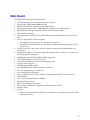
2 Board Set Description
This chapter highlights the main features of the board set. The board set contains the following:
• Main board
• PCI riser board
In addition, the server contains the following system boards:
• SCSI board
• Peripheral board
Major components of the board set include:
• Intel Itanium 2 processors
• Intel E8870 chip set
• High-capacity DDR SDRAM memory
• High-bandwidth I/O subsystem supporting PCI and PCI-X
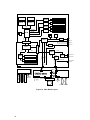
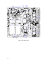
Figure 16 displays a block diagram of the system and the board set within the system.
39
Main Board
Power Pod
Power Pod
ItaniumR
R
Itanium 2
DIMM
MRH-D
2
DIMM
DIMM
MRH-D
DIMM
DIMM
MRH-D
FSB
RDRAM0
DIMM
DIMM
MRH-D
DIMM
RDRAM1
FWH
LPC
SNC-M
RDRAM2
BMC
FWH
LPC
SP2
SP1
RDRAM3
Super IO
ICH-4
EMP
USB Port
PCI 33
VHDM Connector
HL-1.5
SIOH
P64H2
USB Port
Video Port
Video
Internal SCSI
IDE
100 MHz PCI-X
Docking Connector
Ethernet Port
SCSI Cable
Front Panel
Ribbon
Cable
SCSI Backplane
USB Port
To SCSI
Backplane
USB Port
Y-Cable
Video Port
Power Supply
Power Supply
Ethernet Port
External SCSI
Flex Cable
Power Bay
Dual GBit
Ethernet
SCSI
320
VGA
2x USB
133 MHz PCI-X
100 MHz PCI-X
Power Supply
PCI-X
P64H2
PCI-X
HL-2
HL-2
VHDM Connector
PCI Riser
IDE Cable
DVD Adapter Board
DVD/CD
From Power
Bay
Hot Swap SCSI Drives
Figure 16. Main Board Layout
40
External SCSI
Connector
Main Board
The main board supports the following features:
• Two Intel Itanium 2 processor sockets and power pod sites
• Eight 184-pin, DDR-SDRAM DIMM sockets
• SNC-M (Scalable Node Controller) of the E8870 chip set
• Four Memory Repeater Hubs – DDR (MRH-D) components of the E8870 chip set
• One P64H2 PCI-X bridge component (to drive SCSI controller and NIC)
• SCSI Ultra320 Controller
• Network Interface Controller (NIC) 10/100/1000 Ethernet controller that provides two LAN
ports
• One I/O Control Hub 4 (ICH4) component
•
•
•
•
•
•
•
•
•
•
•
•
•
•
•
•
•
•
Four USB ports (two at the rear, two through the front panel)
One IDE bus routed through the flex cable to the peripheral board supporting one ATA33
master device
Low Pin Count (LPC) Super I/O* with one external serial port and an internal header for a
second port
Integrated ATI* Rage* XL video controller and memory with two video ports – one at the rear
and one through the front panel
8-MB Flash using four Firmware Hub (FWH) components
Two VHDM connectors for PCI riser board
Two retention mechanisms for processors and power pods
In-Target Probe (ITP) port
200-MHz Front Side Bus (FSB)
Four 400-MHz Rambus channels for memory interface
Core ratio programming via the SNC-M
Server management logic support
Joint Test Action Group (JTAG) / boundary scan support through ITP or external source
Clock buffering
2
Six I C system management buses (SMBus)
Embedded D2D converters
BMC server management controller
Power control - Advanced Configuration and Power Interface (ACPI)
Speaker control
2
I C logic
Includes Field Replaceable Unit (FRU) device ID that is accessed through a private I C bus
2
Temperature sensors
41
Processor Sockets
Each Intel Itanium 2 processor plugs into a 700-pin Zero Insertion Force (ZIF) socket. Each
processor is powered by a 12-V power pod located adjacent to the processor on the main board.
Attached to the top of each processor is a heat sink that dissipates thermal energy.
Memory Subsystem
The basic architecture of the memory subsystem is as follows:
• The DIMMs reside on the main board, between the PCI riser assembly and the chassis.
• Four Rambus channels run from the Scalable Node Controller (SNC) to each of the four
Memory Repeater Hubs (MRH-D).
• There is one MRH-D device per Rambus channel.
• Each MRH-D supports two DDR branch channels.
• Each DDR branch channel supports two 184-pin DDR DIMMs.
• The server system includes eight DIMM connectors in two rows.
• Each row of DIMM sockets supports four DDR DIMMs, one channel of each MRH-D, which
collectively make up a cache line.
The DIMM socket locations are shown in Figure 17.
Figure 17. Location of Memory DIMMS
42
NOTES
The BIOS automatically detects, sizes, and initializes the memory array,
depending on the type, size, and speed of the installed DIMMs. The BIOS
reports memory size and allocation to the system through configuration
registers.
The system does not support mixed-sized DIMMs or DIMMs from different
vendors within the same row.
DIMMs must be populated in groups of four, referred to as a row. Row 1 consists of DIMM
sockets 1-4 and row 2 consists of DIMM sockets 5-8. The DIMM sockets in each row are not sideby-side; see Figure 17 to identify each socket and row.
Within a single row, all DIMMs must be identical, both in DIMM size and the number of devices
on the DIMM. Each of the two DIMM rows can be populated with DIMMs that use different
technologies, but for the best performance, the amount of memory on each MRH-D DDR branch
channel should be the same to enable the benefits of memory interleaving.
SCSI Controller
The LSI-531030 SCSI controller (U320) on the main board provides one primary channel to the
internal SCSI backplane and a secondary channel via an external SCSI connector at the rear of the
chassis. This device interfaces to the SIOH at clock frequencies up to133 MHz through one
channel of the primary P64H2, also located on the main board. The 53C1030 is a fully autonomous
device, capable of managing multiple I/O operations and associated data transfers from start to
finish without host intervention.
While the internal channel supports only Low Voltage Differential (LVD) signaling, the external
channel supports both LVD and SE (single-ended) signaling. With LVD signaling, the channels
can each support a maximum data rate of 320 MB/sec.
Network Interface Controller
The onboard network interface is composed of one Intel 82546EB Dual Port Gigabit Ethernet
controller connected to the second channel of the primary P64H2 PCI-X bridge, located on the
main board, at clock frequencies up to133 MHz. The 82546EB is a single component with two
fully IEEE 802.3-compliant Ethernet interfaces. It provides two stacked RJ45 ports at the rear of
the chassis.
This network interface supports Ethernet applications at 1000Base-T, 100Base-T, and 10Base-T
(802.3, 802.3u and 802.3ab) and enables network manageability implementations required for
remote control and alert over LAN.
43
Video Controller
The onboard, integrated ATI RAGE XL 64-bit SVGA chip contains an SVGA controller that is
fully compatible with industry video standards. The video sub-system implements 8 MB of
10-nanosecond onboard video memory.
The video controller supports pixel resolutions of up to 1600 x 1200 and up to 16.7 million colors
and provides hardware-accelerated bit block transfers of data. The SVGA controller supports
analog VGA monitors (single and multiple frequency, interlaced and noninterlaced) with a
maximum vertical retrace noninterlaced frequency of 100 Hz.
Video connectors are located at both the front and the rear of the chassis. The connectors are auto
sensed and only one can be used at a time.
IDE Controller
®
The IDE controller is contained within the Intel ICH4 (82801DA). The IDE controller is a
multifunction device on the I/O board that acts as a PCI-based Fast IDE controller. Although the
server system implements a single IDE channel on the peripheral board, which supports a CD/DVD
drive at ATA-33 speeds, the IDE controller supports the following:
• PIO and IDE DMA/bus master operations
• Mode 4 timing
• ATA-100 (100 MB/sec using ultra DMA transfers)
• Buffering for PCI/IDE burst transfers
• Master/slave IDE mode
Baseboard Management Controller (BMC)
The Baseboard Management Controller and its associated circuitry reside on the main board. The
BMC autonomously monitors system platform management events and logs their occurrences in the
nonvolatile System Event Log (SEL). This includes events such as over-temperature and overvoltage conditions, and fan failures. The BMC provides the interface to the monitored information
so system management software can poll and retrieve the present status of the platform.
The BMC provides the interface to the nonvolatile Sensor Data Record (SDR) Repository. Sensor
Data Records provide a set of information that system management software can use to
automatically configure itself for the number and type of IPMI sensors (such as temperature and
voltage sensors) in the system.
44
The following is a list of the major functions of the BMC:
• System power control, including providing Sleep/Wake push-button interfaces for ACPI
• Platform Event Paging / Platform Event Filtering
• Power distribution board monitoring
• Temperature and voltage monitoring
• Fan failure monitoring
• Processor presence monitoring (no processors installed)
• Interlock monitoring
• Speaker beep capability on standby and when system is powered up
• Intel Itanium 2 processor SEEPROM interface (for processor information ROM and scratch
EEPROM access)
• Processor temperature monitoring
• Processor core ratio speed setting
• Chassis general fault light control
• Chassis cooling failure light control
• Chassis power fault light control
• Chassis power light control
• Chassis ID LEDs control
• System Event Log interface
• Sensor Data Record repository interface
• SDR/SEL timestamp clock
• Board set FRU information interface
• Fault resilient booting
• System management watchdog timer
• Front panel system diagnostic-interrupt handling
• Platform Management Interruption / System Diagnostic Interrupt status monitor
• Event receiver
• System interface to the IPMB (via system interface ports)
• IPMI Management Controller Initialization Agent
• Emergency Management Port interface
• Serial/modem and LAN alerting
The firmware for the BMC is field-upgradeable using the Firmware Update utility. For information
on the Firmware Update Utility, see Running the Firmware Update Utility.
45
PCI Riser Board
The PCI riser board supports the following features:
• One Server I/O Hub (SIOH) component of the E8870 chip set
• One P64H2 component
• Three non-hot-plug PCI slots
•
•
•
One 64-bit, 133-MHz PCI-X, full length
Two 64-bit, 100-MHz PCI-X, full-length
One integrated D2D
Server management logic
2
I C logic
FRU device ID accessed through a private I C bus
2
Temperature sensor
SCSI Backplane Board
The SCSI backplane board communicates with the main board via a 68-pin SCSI cable and a flex
cable. It contains two industry-standard 80-pin Single Connector Attachment (SCA)-2 connectors
for hot-swap hard drives. Ultra320 or lower SCSI technology SCA type hard drives can be
installed in this carrier. The backplane board accepts hard drives up to 15,000 RPM.
The features supported by the SCSI backplane board include the following:
•
•
Monitoring the SCSI bus for enclosure services messages and acting on them appropriately.
Examples of such messages include: activate a drive fault indicator, power down a drive that
has failed, and report SCSI backplane temperature.
2
SAF-TE intelligent agent, which acts as proxy for “dumb” I C devices during intrachassis
2
communications. “Dumb” I C devices are those that have no bus mastering capability.
NOTE
Because all hard drives have different cooling, power and vibration
characteristics, Intel validates specific hard drive types in the system.
The SCSI backplane provides three main functions for the system:
• Passes the SCSI signals between the main board and the SCSI drives
• Provides hooks for enclosure management
2
• Provides an I C server management interface
46
The SCSI backplane functional blocks include the following:
• Ultra320 LVD SCSI bus passes SCSI signals between the SCSI drives and the main board
A standard 68-pin SCSI connector provides the SCSI connection from the main board to
the SCSI backplane.
•
•
Two 80-pin (SCA-2 blind-mate) connectors are located on the SCSI backplane board to
mate with hot-swap LVD SCSI drives in the drive bay.
Fault Tolerant Enclosure Management
SAF-TE
SCSI power control
LED control logic
Server management
I C interface
2
I C Serial CMOS EEPROM (FRU)
Temperature sensor
2
QLogic* GEM359* SCSI Hot-swap Controller
The QLogic GEM359 Hot-swap Controller resides on the SCSI backplane board. The primary
functions of the GEM359 are as follows:
• Implements the SAF-TE command set
• Controls the SCSI hard drive fault LEDs
• Provides a path for management information via the SCSI
• Retrieves hard drive fault status, SCSI backplane temperature, and fan failure information via
the IPMB
• Queries the status of the power distribution board by retrieving information from the BMC via
the IPMB
• Controls hard drive power-on and power-down, facilitating hot-swapping
47
Peripheral Board
The peripheral board provides three main functions for the system:
• Passes the IDE signals between the main board and the DVD drive
• Provides the front panel interface for the system
2
• Provides I C server management interface
Peripheral Board Functional Blocks
•
•
•
IDE bus passes IDE signals between the IDE DVD and the main board
The 120-pin flex cable connector from main board provides IDE connectivity and auxiliary
signals
Single IDE channel pass-thru connection to IDE connector for support of an IDE peripheral
Front panel functions
Two USB 1.1 connections
Power, Reset, SDINT and ID buttons
LEDs for power, both NIC channels, ID, system and drive failure
VGA connector providing video from main board controller
Server management
I C isolation to SCSI board
Temperature sensor
2
Peripheral Interface
The server connects to supported peripheral devices through interfaces located on the main board.
The ICH-4 on this board provides the following:
• Four USB 1.1 ports (two located in front and two located at the rear)
• Two serial ports, one internal port (10-pin header) and one port at the rear (serial RJ45)
• One PCI connection to onboard video (VGA ports located front and rear)
• One IDE channel for the CD/DVD
48
Server Management
The server management features are implemented using two microcontrollers: the Baseboard
Management Controller on the main and the Qlogic* GEM359 SCSI hot-swap controller on the
SCSI backplane board. For information about these microcontrollers, see:
• Baseboard Management Controller (BMC)
• QLogic* GEM359* SCSI Hot-swap Controller
49
3 Configuration Software and Utilities
Utilities / Drivers on Resource CD
The Resource CD included with your server system includes the following utilities and drivers that
can be used to configure your system:
• LSI Logic SCSI Driver for Linux (64-bit) and Microsoft Windows* 2003 Server
• Utilities:
•
FRUSDR Loader
EFI Platform Diagnostics
System Maintenance Utility (SMU)
• SDRViewer
• SELViewer
EFI Configuration Tool
The Resource CD includes a menu-driven program that can be used for the following:
• Create a diskette containing drivers for various operating systems.
• Install EFI Service Partition. The EFI service partition provides the ability to remotely access
the server via modem or LAN for the purpose of executing configuration/setup utilities and
diagnostics.
• Run EFI-based utilities.
Running Software Utilities Directly from the Resource CD
The following procedure allows you to run the software utilities directly from the Resource CD.
1. Insert the System Resource CD into the server’s CD-ROM drive before booting to EFI Shell.
2. Boot the system into EFI Shell; the EFI CD menu program launches automatically. If the EFI
CD menu program does not launch in the EFI Shell, mount and map to the CD drive and type
startup and press <Enter> to launch the EFI CD menu.
3. Move the curser to the Utilities and select the utility you want to run.
Power-on Sequence and Power-on Self-Test (POST)
Turning on the system causes POST to run and control to pass to the boot manager. From the boot
manager, you can choose to invoke the Extensible Firmware Interface (EFI) Shell or you can
choose to go to the Boot Maintenance menu.
50
The following process occurs when you press the power button on the front control panel to power
up the server:
1. The server fans start.
2. POST begins running. POST is stored in flash memory. It checks the drive carriers,
processors, memory, keyboard, and most installed peripheral devices. During the memory test,
POST displays the amount of memory it is able to access and test. The length of time needed
to test the memory depends on the amount of memory installed.
3. Video appears on the monitor that is attached to the server and begins to display boot progress.
The AMI* BIOS banner displays the loaded versions of the BIOS, PAL, SAL, and EFI.
4. POST concludes and passes control to the boot manager.
5. From the boot manager, you can use arrow keys to highlight the option that invokes the EFI
shell operating system if it is installed, or you can highlight and select the Boot Maintenance
menu. Selecting the Boot Maintenance menu lets you configure boot options and other boot
environment variables. Booting to the EFI shell causes the following prompt to appear:
Shell>
6. When you see this prompt, you can load and start an operating system.
Extensible Firmware Interface Boot Manager
The EFI boot manager allows you to control the server’s booting environment. Depending on how
you have configured the boot options, after the server is powered up the boot manager presents you
with different ways to bring up the system. For example, you can boot to one of the following:
EFI Shell: An interactive environment that allows EFI device drivers to be loaded, EFI
applications to be launched, and operating systems to be booted. The EFI shell provides a set of
basic commands used to manage files and the system environment variables. For more information
on the EFI Shell, see The Extensible Firmware Interface (EFI) Shell.
Boot Options: Files that you include as boot options. You add and delete boot options by using
the Boot Maintenance menu. Each boot option specifies an EFI executable with possible options.
For information on the Boot Maintenance menu options, see Table 4.
Boot Maintenance Menu: A menu of items allowing you configure boot options and other boot
environment variables. Table 4 describes each menu item in the Boot Maintenance menu.
Table 4.
Boot Maintenance Menu Options
Option
Description
Boot from a File
Automatically adds EFI applications as boot options or allows you to boot
from a specific file.
When you choose this option, the system searches for an EFI directory in all
EFI System Partitions in the system. For each EFI directory that the system
finds, it searches through that directory’s subdirectories for the first file that
is an executable EFI application. Each file that meets this criterion can be
automatically added as a boot option. In addition, legacy boot options for A:
and C: are also added if those devices are present.
With this option, you can launch a specific application without adding it as a
boot option. In this case, the EFI Boot Manager searches the root
directories of all of the EFI System Partitions present in the system for the
specified EFI application.
51
Option
Description
To boot from a file:
•
•
•
•
Add a Boot Option
At the menu, use the arrow key to select Boot from a File.
Press <Enter> to select the option.
Use the arrow key to choose the EFI file to boot from.
Press <Enter> to select the option.
Adds a boot option to the EFI Boot Manager. You specify the option by
providing the name of the EFI application. You can provide either ASCII or
UNICODE arguments that the file might use.
Given the EFI application name and any options, the EFI Boot Manager
searches for the executable file in the same partitions and directories as
described in Boot from a File. When the file is found, it is executed.
To add a boot option:
•
•
•
•
•
Delete Boot Options
This feature allows you to delete a specific boot option or all boot options.
To delete boot options:
•
•
•
•
•
•
•
Change Boot Order
At the menu, use the arrow key to select Delete Boot Option.
Press <Enter> to select the option.
Use the arrow keys to select the boot option to delete.
Press <Enter> to select the option.
Press <Y> to confirm your selection.
Select Save to NVRAM.
Select Exit to return to the Boot Manager.
This feature allows you to control the relative order in which the EFI Boot
Manager attempts boot options. For help on the control key sequences you
need for this option, refer to the help menu. To change the boot order:
•
•
•
•
•
•
Manage BootNext Setting
At the menu, use the arrow key to select Add Boot.
Press <Enter> to select the option.
Type in the name of the EFI application and press <Enter>.
Select Save to NVRAM.
Select Exit to return to the Boot Manager.
At the menu, use the arrow key to select Change Boot Order.
Use the arrow keys to select the Option to move.
Press <u> to move up in the boot order.
Press <d> to move down in the boot order.
Select Save to NVRAM.
Select Exit to return to the Boot Manager.
This feature allows you to select a boot option to use one time (the next
boot operation).
To manage boot next setting:
•
•
•
•
•
•
Set Auto Boot Timeout
52
At the menu, select Manage Boot Next Setting with the arrow
key.
Select the Option to boot next with the arrow key.
Press <b> to make this option the next boot option.
Press <r> to reset.
Select Save to NVRAM.
Select Exit to return to the Boot Manager.
This feature allows you to define the value in seconds that pass before the
system automatically boots without user intervention. Setting this value to
Option
Description
zero disables the timeout feature.
To set auto boot timeout:
•
•
•
•
•
Select Console Output
Device
At the menu, select Set Auto Boot Timeout with the arrow key.
Three options are available.
Select the Choose Value option with the arrow key and enter a
value of “0” to disable auto boot.
Select the Delete option with the arrow key and select the
Delete setting with the arrow key and press <Enter>.
Choose a time out value of 65535 (0xFFFF) to allow you to
press any key while booting to EFI to disable timeout.
This feature allows you to select the device that the console output is
sent to.
To select the console output device:
•
•
•
•
•
•
Select Console Input Device
At the menu, select Manage Boot Next Setting with the arrow
key.
Select the Option to boot next with the arrow key
Press <b> to make this option the next boot option.
Press <r> to reset.
Select Save to NVRAM.
Select Exit to return to the Boot Manager.
This feature allows you to select the device that the console receives
input from.
To select the console input device:
•
•
•
•
•
•
Select Standard Error Device
At the menu, select Manage Boot Next Setting with the arrow
key.
Select the Option to boot next with the arrow key.
Press <b> to make this option the next boot option.
Press <r> to reset.
Select Save to NVRAM.
Select Exit to return to the Boot Manager.
This feature allows you to select the standard error device.
To select the standard error device:
•
•
•
•
•
•
At the menu, select Manage Boot Next Setting with the arrow
key.
Select the Option to boot next with the arrow key.
Press <b> to make this option the next boot option.
Press <r> to reset.
Select Save to NVRAM.
Select Exit to return to the Boot Manager.
53
Cold Reset
Performs a platform-specific cold reset of the system. A cold reset means a
full platform reset.
To perform a cold reset:
Exit
•
At the menu, select Set Auto Boot Timeout with the arrow key.
•
Press <Enter>.
•
The system resets.
Returns control to the EFI Boot Manager main menu. Selecting this option
displays the active boot devices, including a possible integrated shell.
The Extensible Firmware Interface (EFI) Shell
The EFI shell application allows other EFI applications to be launched, EFI device drivers to be
loaded, and operating systems to be booted. The combination of the EFI firmware and the EFI
shell provides an environment that can be modified to easily adapt to many different hardware
configurations.
The EFI shell provides a set of basic commands used to manage files and EFI NVRAM shell and
boot variables. A list of these basic commands is shown in Table 5. Descriptions of the EFI shell
commands are also available when operating in the EFI Shell. To access the descriptions, type
help and press the <Enter> key.
A detailed description of the commands is available on the EFI website. To obtain the document,
go to http://developer.intel.com/technology/efi. To download the files, click on Tools and then EFI
Sample Implementation 1.10.14.60. The descriptions are in the Microsoft* Word* file named
EFI1.1ShellCommands.doc.
In addition to the standard shell commands available in the EFI Shell, the EFI environment allows
you to create your own shell commands and EFI applications. For detailed information about the
EFI Shell, its commands, and the ability to develop within the environment, refer to the EFI
Developer’s Guide at http://developer.intel.com/technology/efi. Click on Tools and then EFI
Sample Implementation Version 1.02 to download the files to your hard drive. Review the
Microsoft Word file Efi_dg.doc.
To develop your own shell commands, download the EFI Application Toolkit under the Tools link
at http://developer.intel.com/technology/efi
Table 5.
EFI Shell Commands
Command
Description
<drive_name>:
Changes drives. For example, entering fs0: and pressing
the <Enter> key changes the drive
alias [-bdv] [sname] [value]
Sets or gets alias settings
attrib [-b] [+/- rhs] [file]
Views or sets file attributes
bcfg -?
Configures boot driver and load options in EFI NVRAM
botmaint
Launches Boot Maintenance Manager
break
Executes a breakpoint
cd [path]
Changes the current directory
54
Command
Description
cls [background color]
Clears the screen
comp file1 file2
Compares two files
connect [-r] [-c] Handle# ½DeviceHandle#
DriverHandle#
Binds the EFI driver to a device and starts the driver
cp [-r] file [file] ... [dest]
Copies files and directories, [-r] = recursive
date [mm/dd/yyyy]
Gets or sets the date
dblk device [Lba] [Blocks]
Performs a hex dump of BlkIo Devices
devices [-b] [-1XXX]
Displays devices
devtree [-b] [-d]
Displays device tree
dh [-b] [-p prot_id] | [handle]
Dumps handle information
disconnect DeviceHandle#
[DriverHandle# [ChildHandle#]
Disconnects device from driver
dmem {address] [size] [;MMIO]
Displays the contents of memory
dmpstore
Dumps the variable store
drivers [-b] [-lXXX]
Displays drivers
drvcfg [-c] [-lXXX] [-f] [-v] [-s]
Invokes the driver configuration protocol
drvdiag [-c] [-lXXX] [-s] [-e] [-m]
Invokes the driver diagnostics protocol
echo [[-on | -off] | [text]
Echoes text to the standard output device or toggles script
echo
edit [filename]
Opens the text editor allowing you to create or edit a file
eficompress infile outfile
Compresses an EFI file
Efidecompress infile outfile
Decompresses an EFI file
endfor
Provides a delimiter for loop constructs (scripts only)
endif
Provides a delimiter for IF THEN constructs (scripts only)
for var in <set>
goto label
Makes batch file execution jump to another label
guid [-b] [sname]
Dumps known guid ids
help [-b] [internal_command]
Displays help information
hexedit [[-f]FileName|[-d DiskName Offset
Size]|[-m Offset Size]]
Edits in HEX mode
if [not] condition then
Provides conditional constructs (scripts only)
load driver_name
Loads a driver
loadbmp [-c] [-t] [-i[UGA Instance]] file
Displays a bitmap file on the screen
loadpcirom romfile
Loads a PCI option ROM
ls [-b] [dir] [dir] ...
Obtains directory listings
map [-bdvr] [sname[:]] [handle]
Maps sname to device path
mem [address] [size] [;MMIO]
Dumps Memory or Memory Mapped IO
memmap [-b]
Dumps memory map
mkdir dir [dir]
Creates a new directory
mm address [Width] [;Type] [n]
Memory Modify: type = Mem, MMIO, IO, PCI, [n] for non
interactive mode when inside a .nsh file
mode [col row]
Sets or gets the current graphics mode
55
Command
Description
mount BlkDevice [sname[:]]
Mounts a file system on a block device
mv [src…] [dst]
Move one or more files/directories to destination
pause
Prompts to quit or continue (scripts only)
pci [bus_dev] [func]
Displays PCI device information
rconnect DeviceHandle# [DriverHandle#
[ChildHandle#]] | [-r]
Reconnects one or more drivers from a device
reset [reset_string]
Performs a cold reset
rm file/dir [file/dir]
Removes files or directories
setsize file
Sets size of a new file
stall microseconds
Delays for the specified number of microseconds
time [hh:mm:ss]
Gets or sets the time
type [-a] [-u] [-b] file
Displays the contents of a file
ver
Displays version information
vol fs [volume_label]
Sets or displays a volume label
Firmware Upgrades
Use the Firmware Update Utility to upgrade the firmware. This utility is an EFI application that
updates the following server management controllers:
• Baseboard Management Controller (BMC)
• Hot-swap Controller (HSC)
You can run the utility interactively by providing commands through the EFI shell, or you can run
it in non-interactive mode by supplying the command with any options. For information on the
command-line options, see Table 6.
NOTE
Review the firmware release notes that come with the software for additional
instructions before updating either the boot code or the operational code.
56
Running the Firmware Update Utility
The following procedure shows how to use the interactive method to upgrade the firmware with the
Firmware Update Utility.
1. Boot to the EFI Shell.
2. Contact your Intel Sales Representative for the current release of the files:
FWUpdate.efi
IPMI.efi
<name>.hex
IPMIdriver.txt
Firmwareupdate.txt
<name>.txt
Where <name> represents the hex image for the controller being updated. For example, the files
lnbmc11.hex and lnbmc11.txt represent the firmware and release note files, respectively for BMC
release 11. Write down the name of the HEX file because you will need it later.
You can update the firmware either by the Firmware Update Utility’s command-line interface or
through the GUI interface.
Firmware Update with Command-line Interface
Table 6 describes the command-line options for the Firmware Update Utility.
Table 6.
Firmware Update Utility Command-line Options and Parameters
Option or
Parameter
Description
FWUpdate
The name of the utility.
[Hex_File_Name]
The name of the input hex file used for the update/verification. The file path can be
specified with the file name. There is no default filename or extension.
/h Or /?
Display command-line help.
/uploadpia
Upload the FW flash with the Platform Information Area (PIA) contained in the hex
file.
/upload
Upload the FW flash with the operational code contained in the hex file. The
Platform Information Area (PIA) will also be uploaded, if it is present in the hex file.
Upon completion, the firmware is verified against the hex file to ensure the upload
was successful.
/norestore
When used in conjunction with /upload, the utility does not restore the user
configuration settings after performing the update. Without this switch, the utility
saves the user configurations prior to updating the FW, and then restores the saved
user configuration settings after updating the FW.
/noverify
When used in conjunction with /upload or /uploadpia, the utility does not compare
the flash against the hex file after performing the update, as is usually done to verify
a successful update. When not used in conjunction with /upload or /uploadpia, this
switch has no effect.
57
/ignorerevs
When used in conjunction with /upload or /uploadpia, the firmware version in the
hex file is not checked. Without this switch, the utility only allows uploading a
version of the firmware that is greater than or equal to the version being replaced.
When not used in conjunction with /upload or /uploadpia, this switch has no effect.
/nopc
When used in conjunction with /upload or /uploadpia, the platform check is disabled.
Without this switch, the utility only allows uploading firmware that is intended for the
target platform. The target platform is determined by reading the BIOS ID of the
system and compares it against the Platform Name field in the boot code info block
of the hex file. In the case of the PIA, the target platform is determined from the
Platform Group and Platform ID fields of the PIA info block. When not used in
conjunction with /upload or /uploadpia, this switch has no effect.
/bootena
When used in conjunction with /upload, the boot-block of the device is uploaded in
addition to the operational code and PIA if present in the hex file. NOTE: An
external jumper may be required in order to enable the boot block to be uploaded.
On systems requiring the jumper, the boot block upload fails if the jumper is not set,
and an error is generated indicating that the boot block could not be uploaded.
However, the utility still attempts to upload the operation code and PIA, if present in
the hex file. This switch may only be used in conjunction with /upload.
/verify
Verify the firmware. The utility compares the flash contents of boot code, operation
code, and PIA (if applicable), with that contained in the hex file.
/fwversion
Display firmware version, for all supported devices in the system.
/secondary
Select secondary controller; e.g. second hot-swap controller. The primary and
secondary controllers are identical, this switch indicates which one is being updated
or verified. Without this switch the primary controller is assumed. When not used in
conjunction with /upload or /verify, this switch has no effect.
/infoblock
Display device info block of input hex file.
/nopause
Suppresses keyboard wait at end of transfer or on an error. This switch allows
updates to be performed in a batch style environment without requiring user
interaction.
To run the Firmware Update Utility through the command-line interface:
1. Start the utility by typing: fwupdate [HEX File Name] [Options]
2. To view the command-line help, type:
fwupdate /h
or
fwupdate /?
3. To update boot block and the operational block of the firmware from the command-line
interface, type fwupdate [HEX File Name] /upload /bootena
An external jumper may be required in order to enable the boot block to be uploaded.
4. To update the operational block only from the command-line interface, type fwupdate
[HEX File Name] /upload
58
After the update completes successfully, the utility verifies the update by reading back the
programmed code and comparing it to the HEX file.
5. Select the File menu and choose Exit to exit the utility.
6. If you need to update the firmware for additional controllers, repeat the above steps for each
controller.
7. Power down the system by pressing and holding the power button on the front control panel.
8. Disconnect the AC power cords from the system and wait 60 seconds.
9. Connect the AC power cords and power up the system by pressing the power button.
Firmware Update with GUI Interface
To run the Firmware Update Utility through the GUI interface:
1. Start the utility by typing fwupdate <name>.hex
In the command, <name>.hex is the file you wrote down earlier.
2. Wait for the HEX file to load and the utility to display its menu items.
3. Use the arrow keys to select the Update Flash menu item.
4. Press the <Enter> key.
5. The utility asks you to update the boot code and/or the operational code.
After the update completes successfully, the utility verifies the update by reading back the
programmed code and comparing it to the HEX file.
6. Select the File menu and choose Exit to exit the utility.
7. If you need to update the firmware for additional controllers, repeat the above steps for each
controller.
8. Power down the system by pressing and holding the power button on the front control panel.
9. Disconnect the AC power cords from the system and wait 60 seconds.
10. Connect the AC power cords and power up the system by pressing the power button.
BIOS Upgrades
The BIOS is implemented as firmware that resides in flash ROMs. Use the EFI (Extensible
Firmware Interface) based utility IFlash64.EFI to upgrade the BIOS.
NOTE
After you complete the Iflash64 BIOS update, you must clear the CMOS.
For information on how to clear CMOS, refer to CMOS Clear.
59
BIOS Upgrade Procedure
A BIOS upgrade procedure can be done using the latest available System Update Package (SUP)
for the system. This is a script file that automatically runs IFlash64 and other firmware update
utilities. You can also use the IFlash64 utility to upgrade the BIOS using the following steps:
1. Boot to the EFI Shell. For information on how to boot the server, refer to The Extensible
Firmware Interface (EFI) Shell.
2. Copy IFlash64.EFI to a hard disk, CD-ROM disk, or EFI ramdisk (EFI ramdisk driver
required). The binary file contains the new BIOS. Refer to the update instructions provided
with each BIOS release for the most current instructions.
IFlash64 with Command-line Interface
Table 7 lists the command-line options for the IFlash64 Utility.
Table 7.
IFlash64 Utility Command-line Options and Parameters
Parameter
Description
Iflash64
The name of the utility.
[Volume_File_Name]
Name of the BIOS binary volume file used for the update. The file path can be
specified with the file name. There is no default file name.
/d
Display header and FLASH areas information of volume file.
/f
Load default values from CMOS on next boot.
/quiet
Quiet or non-interactive mode. It displays only error messages and disables
prompting you for input.
/reboot
Reboot system after update.
/update
Update system BIOS in non-interactive mode. Note that it only updates flash
areas that are different than the ones found in the input binary file. Use “/o” to
override this default operation.
/verify
Verify current Flash with contents of input binary file in non-interactive mode.
/h Or /?
Displays command-line help.
Running the IFlash64 utility through the command-line interface:
1. Start the utility by typing IFlash64 [File Name] [Options]
2. To view the command-line help, type:
IFlash64 /h
or
IFlash64 /?
3. To update System BIOS from the command-line interface, type, IFlash64 [File Name]
/update
4. To verify System BIOS from the command-line interface, type, IFlash64 [File Name]
/verify
IFlash64 with GUI Interface
Running the IFlash64 Utility through the GUI Interface:
60
1. Start the utility by typing IFlash64 or IFlash64 [File Name]
2. Use the arrow keys to browse through the menu and press the <Enter> key to select. A brief
description of the selected menu item is displayed in the Tip-View window.
3. To update System BIOS from the GUI interface, select Update System BIOS.
4. To verify System BIOS from the GUI interface, select Verify System BIOS.
5. Turn off the computer and follow the procedure to clear CMOS as described in CMOS Clear.
CMOS Clear
You must clear the CMOS after you update the BIOS. Clearing the CMOS involves changing a
jumper setting on the I/O riser card, restarting the server with the new jumper setting, restoring the
jumper setting to its original position, and restarting the server a final time.
WARNING
Warnings and cautions apply whenever the top cover of the system is
removed. Only a trained service technician should integrate, configure,
or service this system. See Important Safety Information before opening
your server system.
To clear CMOS follow these steps:
1. Power down the server by pressing and holding down the power button on the front control
panel. You might need to hold the power button down for several seconds.
2. Unplug both power cords from the server.
3. Remove the top cover from the chassis. See Removing and Installing the Top Cover.
4. Move the jumper at J5H3 from pins 1-2 to pins 2-3
5. Plug the power cords back in.
6. Power on the server by pressing the power button on the front control panel.
7. Wait for the message NVRAM cleared by jumper to appear. When the following
message appears, press <F1> to load the defaults:
Press <F1> to load defaults or <F2> to run SETUP or <ESC> to
continue
8. Power down the server by pressing and holding the power button on the front control panel.
You might need to hold down the power button for several seconds.
9. Unplug both power cords from the server.
10. Move the jumper at J5H3 from pins 2-3 to pins 1-2.
11. Install the chassis cover. See Removing and Installing the Top Cover.
12. Plug the power cords back in.
13. Power on the server by pressing and holding the power button on the front control panel.
61
BIOS Recovery Mode
The BIOS Recovery Mode permits reflashing the BIOS when the flash ROM has been corrupted.
The sequence of events for automatic recovery is:
1. Insert recovery media and reset the system.
2. One beep indicates recovery media valid, and flash update started.
3. Approximately two minutes later, two beeps indicate flash update complete.
4. System automatically resets and starts the new BIOS.
WARNING
Warnings and cautions apply whenever the top cover of the system is
removed. Only a trained service technician should integrate, configure,
or service this system. See Important Safety Information before opening
your server system.
NOTE
BIOS recovery requires an “El Torito” formatted CD; alternate forms of
removable media including USB devices are not supported and will result in
a continuous beep code (approximately 1 beep every 2 seconds until the
system is powered down).
The BIOS Recovery Mode is initiated using the following procedure:
1. Unzip the recovery image and copy the SR870BH2.REC file onto the CD. SR870BH2.REC
should be the only file on the disk.
2. Power down the server.
3. Unplug both power cords from the server.
4. Remove the top cover from the chassis. See Removing and Installing the Top Cover.
5. Move the jumper at J5H1 Labeled ‘RCV BOOT’ from pins 1-2 to pins 2-3.
6. Reconnect the AC power and switch server power on. CD Recovery activity begins. One full
beep is emitted as the server begins to load SR870BH2.REC from disk to memory.
7. Wait two minutes. Two beeps indicate the BIOS recovery has completed successfully.
8. Remove the CD and power down the server.
9. Unplug both power cords from the server.
10. Move the jumper at J5H1 from pins 2-3 to pins 1-2.
11. Install the chassis cover. See Removing and Installing the Top Cover.
12. Reconnect AC power and power on the server.
13. Follow any other instructions in the BIOS release notes.
62
FRUSDR Load Utility
The Field Replacement Unit (FRU) and Sensor Data Record (SDR) Load Utility (FRUSDR.EFI) is
an Extensible Firmware Interface program that updates or modifies the server management
subsystem’s product level FRU and SDR repository. This utility is used to program, compare, or
display FRU and/or SDR information. It must be run on an Intel Itanium 2 system executing
NSHELL under the EFI environment.
You should run the FRUSDR Load Utility each time you upgrade or replace the hardware in your
server; excluding add-in boards, hard drives, and RAM. The utility programs the sensors that the
server uses to monitor server management. Upon completing the programming of the FRU and/or
SDR areas, the server should be rebooted.
The normal method of loading one or more FRU files is through the use of a configuration file.
Each FRU file name is specified using the FRUNAME configuration command. The first time a
FRU file is programmed, all areas in the FRU file need to be written. This initialization should be
done in manufacturing. The FRUSDR utility does not support first time programming of FRU
areas.
Once the FRU file has been initially programmed, then you may use the FRUSDR utility to update
specific FRU areas and fields. You may not change the size of any FRU area from the size defined
in the original FRU Header. Through the use of a configuration file, each area of the FRU may
selectively be programmed. The FRU information written to the nonvolatile storage device is
verified after programming and an appropriate message is displayed. For more detailed information
on creating and using a configuration file see Configuration File.
Within the FRU file header is a pad byte that can be any one-byte value. This pad byte is used in
calculating the header checksum. If the header checksum is incorrect, then a message is displayed.
The normal method of loading an SDR file is through the use of a configuration file. Typically all
possible Sensor Data Records exist in one master SDR file. Each SDR file name is specified after
the SDRNAME configuration command. Through the configuration file, tags may be use to
selectively chose which records are to be programmed using tags. The maximum allowable length
of any Sensor Data Record is 64 bytes. Any larger records are flagged as an error.
Using the FRUSDR Load Utility, you can do the following:
• Discover the product configuration based on instructions in a master configuration file.
• Display the FRU information.
• Update the nonvolatile storage device associated with the baseboard management controller
(BMC) that holds the SDR and FRU information.
• Generically handle FRU devices that might not be associated with the BMC.
• Supply command lines and interactive input through the standard input device.
• View and direct results to the standard output device.
63
Running the FRUSDR Load Utility
Use the FRUSDR Load Utility to manage the server management subsystem’s product level FRU
and SDR repository. Follow these steps to run the FRUSDR Load Utility:
1. Boot to the EFI Shell. For information on how to boot the server, refer to Booting from the
Service Partition.
2. Copy the FRUSDR package to a removable media or to the hard drive. You will find the
FRUSDR package on the CD-ROM that shipped with the server.
3. Load the IPMI driver by typing load ipmi.efi
NOTE
The IPMI driver file name may change independently of the FRUSDR Load
Utility.
4. Run the utility by entering a frusdr command based on the following syntax: frusdr
[option] [/p]
The frusdr command accepts single options only. You can accompany any option with the /p
switch to cause the output to pause between blocks of displayed output. For descriptions of the
FRUSDR Load Utility command-line options, see FRUSDR Load Utility Command-line
Options.
5. After using the utility, reboot the system by powering off the server and then powering it back
on. The reboot operation is necessary to reload the firmware and initialize the sensors.
FRUSDR Load Utility Command-line Options
The basic command-line format is:
frusdr [/?] [/h] [/p] [/d { fru, sdr}] [/Cfg filename.cfg]
Where:
/? or /H
Displays usage information
/D SDR
Displays the sensor data records
/D FRU
(Address)
Displays the FRU located at a given address, allowing any FRU to be displayed.
When the utility is invoked with the /D FRU or /D SDR command-line argument, the
indicated area is displayed. If the given display function fails because of an inability
to parse the data present or hardware failure the utility displays an error message.
The parameters following /D FRU are:
NVS_TYPE
DEVICE_ID
DEV_CNTR
NVS_LUN
DEV_BUS
DEV_ADDRESS
64
/CFG
(filename.cfg)
Uses the specified custom configuration file. If not specified, the name of the CFG
file defaults to MASTER.CFG. The configuration file may be used to load multiple
FRU and SDR files. In the configuration file, each FRU and SDR file name must be
called out. Each FRU area and field to be programmed must also be specified. The
configuration file may be used to prompt or request information from you, and to ask
which FRU areas to program.
/P
Pause the display between blocks of data to prevent the displayed data from scrolling
off the screen. The /P command may be used with all other commands. It causes
the data being displayed on the screen to pause after a pre-determined amount is
written, so that the displayed data does not scroll off the screen. If there is not
enough data to fill a screen, the pause command is ignored.
There are two addressing modes for FRU devices:
• Indirect: FRUSDR /D FRU [NVS_TYPE | DEV_CNTR | NVS_LUN | DEVICE_ID]
• Direct: FRUSDR /D FRU [NVS_TYPE | DEV_CNTR | NVS_LUN | DEV_BUS |
DEV_ADDR]
NVS_TYPE
The type of EEPROM; Either AT24C02, DS1624S, or IMBDEVICE. If not specified,
IMBDEVICE is assumed.
DEV_CNTR
The controller’s IPMB device address; defaults to ‘C20’. Must be prefixed by ‘C’ and must be
three characters in length, including the ‘C’.
NVS_LUN
The Logical Unit Number. Must be prefixed by ‘L’ and defaults to ‘L00’. LUN value may be
any number between 0 – 3, though any value except the default is uncommon.
DEVICE_ID
The Device ID; defaults to 00. Used only if NVS_TYPE is IMBDEVICE, (i.e. Indirect
Addressing).
DEV_BUS
The device’s bus number; it has no default. Required if NVS_TYPE is not IMBDEVICE (i.e.
Direct Addressing). It has no default value.
DEV_ADDR
The device’s address; it has no default. Required if NVS_TYPE is not IMBDEVICE (i.e.
Direct Addressing). It has no default value.
All numbers entered for DEV_CNTR, DEV_ID, DEV_BUS, and DEV_ADDR are interpreted as
hexadecimal values, and must be in the range 0 – FF; the NVS_LUN must be 0, 1, 2 or 3. The
command-line arguments may be specified in any order and if one of the arguments is not
specified, then its default value is used, if it has one. If DEV_BUS and DEV_ADDR are specified,
i.e. Direct Addressing is used, then DEV_BUS is assumed to precede DEV_ADDR. If no
arguments are specified for [Address] then the BMC FRU is displayed.
Example of Indirect addressing:
FRUSDR /D FRU
IMBDEVICE
CC0
L0
0
The utility interprets this as DEV_CNTR = 0xC0, NVS_LUN = 0, DEV_ID = 0;
Because many of these values are the default values, the same result could be accomplished with
the following:
FRUSDR /D FRU CC0 0
65
Example of Direct addressing:
FRUSDR /D FRU
AT24C02 C20
L0
9
AA
The utility interprets this as DEV_CNTR = 0x20, NVS_LUN = 0, DEV_BUS = 0x09,
DEV_ADDR = 0xAA.
Because many of the values are the default values, the same result could be accomplished with the
following:
FRUSDR /D FRU
AT24C02
9
AA
Whenever more than one number is listed on the command line, the utility assumes the numbers are
DEV_BUS and DEV_ADDR in that order. Therefore, the following command line would be
interpreted as DEV_CNTR = 0xC0, NVS_LUN = 0, DEV_BUS 0x05, DEV_ADDR = 0xA9.
Since NVS_TYPE is not IMBDEVICE, Direct addressing would be used:
FRUSDR /D FRU
CC0
L0
5
AT24C02
A9
Command-line Precedence
Command-line precedence means that the first command found is operated on, followed by the next
command, and so on. Commands can be divided into two categories:
•
•
Flag commands. The only flag command is the pause (/P) flag command. This flag is used by
the action commands.
Action commands. The action commands are: /?, /D FRU, /D SDR, and /CFG.
The pause command affects only the execution of certain action commands. For example, the
pause flag command provides additional information when used with the help and display FRU and
SDR action commands.
If an action command does not use the pause flag, no error is displayed. If more than one action
command is listed on the command line, an error is displayed and the utility exits.
Displaying Usage Information
When the utility is invoked with the /? or /H command-line arguments, the following message is
displayed:
FRUSDR Load Utility, Version 2.0
Copyright (c) 2002 Intel Corporation, All Rights Reserved
_________________________________________________________________________
Usage:
66
FRUSDR
/? or /H
Displays detailed usage information.
/D SDR
Displays Sensor Data Records.
/D FRU [Address]
Displays the FRU located at a given Address.
/CFG [CFG File]
Uses the specified custom Configuration file.
/P
Pauses the display between blocks of data.
Displaying the FRU Area
The FRU area is displayed in ASCII format when the field is ASCII or as a number when the field
is a number. Each FRU area is headed with the name of the area; each FRU field has a field name
header, followed by the field in ASCII or as a number. The Internal Use area is displayed in hex
format, 16 bytes per line. The board, chassis and product FRU areas are ended with an END OF
FIELDS CODE, which indicate there is no more data in this area.
Example:
FRU IMBDEVICE on Controller 20h, LUN 00h, Device ID 00h
Display Header Area
Common Header Area (Version 1, Length 8)
Internal Area Offset
= 01h
Chassis Area Offset = 0Ah
Board Area Offset = 0Eh
Product Area Offset = 16h
Multi-Record Offset = 00h
Pad
= 00h
Checksum
= D0h
Displaying Internal Use Area
Internal Information Area (Version 0, Length 72)
00 00 00 00 00 00 00 00 00 00 00 00 00 00 00 00
00 00 00 00 00 00 00 00 00 00 00 00 00 00 00 00
00 00 00 00 00 00 00 00 00 00 00 00 00 00 00 00
00 00 00 00 00 00 00 00 00 00 00 00 00 00 00 00
00 00 00 00 00 00 01 00
Displaying Chassis Area
Chassis Information Area (Version 1, Length 32)
Chassis Type
= 11h
Part Number
(ASCII) = SBALMADSTD02PP
Serial Number
(ASCII) = A05884265
END OF FIELDS CODE
Displaying Board Area
Board Information Area (Version 1, Length 64)
Unicode Country Base
= 00h
Manufacturing Time (mins) = 733803
Manufacturer Name (ASCII) = Intel
Product Name
(ASCII) = B440FX DP
Serial Number
(ASCII) = N03121530
Part Number
(ASCII) = 664653-001
Mftr FRU File ID (ASCII) = 0123
END OF FIELDS CODE
67
Displaying Product Area
Product Information Area (Version 1, Length 80)
Unicode Country Base
= 00h
Manufacturer Name (ASCII) = Intel
Product Name
(ASCII) = B440FX DPServer
Part Number
(ASCII) = SBALMADSTD02PP
Product Version
(ASCII) =
Serial Number
(ASCII) = A05884265
Asset Tag
(ASCII) =
Mftr FRU File ID (ASCII) = 0123
END OF FIELDS CODE
Displaying the SDR Area
The SDR nonvolatile storage area is displayed in a hex format. A Sensor Record Number X header
separates the data, where X is the number of that sensor record in the SDR area. The line after the
header is the sensor record data in hex delineated by spaces. Each line holds up to 16 bytes. The
data on each line is followed by the same data in ASCII format; nonprintable characters (ch < 32 ||
ch > 126) are substituted by ‘.’.
Example:
Reading SDR Repository, please
Displaying SDR area
Reading SDR Record #1
0E 00 10 01 37 20 00 0F 05 00
02 00 00 00 04 00 00 C4 02 00
8E FF 00 1B 1B 00 99 95 00 8A
53 43 53 49 2D 42 2D 54 65 72
Reading SDR Record #2
0E 40 10 01 30 20 00 13 05 00
00 00 00 20 29 00 00 1E 02 00
00 FF 00 03 03 00 00 00 00 42
46 41 4E 2D 32
68
wait.........
10
08
8E
6D
F1 F8 02 01 85 ....7 ..........
30 C2 07 91 95 ...........0....
02 02 00 01 CC ................
33
SCSI-B-Term3
10 F1 F8 04 01 05 [email protected] ..........
00 00 00 00 00 00 ... )...........
49 02 02 00 01 C5 .........BI.....
FAN-2
Checking the FRU Data Integrity
The utility needs the FRU Common Header offsets to be correct. The utility checks the Common
Header Area in each NVS device against the FRU file and runs a checksum on it. If the Common
Header Area in the FRU file is correct and matches what is in the NVS device, then the information
is programmed. An incorrect Common Header means the FRU area is corrupted or has not been
initialized.
If the Internal Use Area of the BMC is loaded from the FRU file, then the BMC will be cold reset.
This allows the BMC to re-initializes its internal copy of the Internal Use area from the FRU. The
effect of re-initializing the Internal Use Area is that both the SDR table and the SEL (System Event
Log) table are cleared. All information in both areas is lost and the SDRs must be reprogrammed.
Updating the SDR Non-Volatile Storage Area
After the utility validates the header area of the supplied SDR file, then it updates the SDR
repository area. Before programming begins, the utility clears the SDR repository area. When
loading an SDR file from a Configuration File, the utility filters all tagged Sensor Data Records
using a list of tags determined by you, which represent the product’s configuration. Non-tagged
Sensor Data Records are automatically programmed.
After an update is successfully performed, a single message is displayed and the utility exits. If the
utility fails, then it exits with an error message and an exit code.
Updating the FRU Non-Volatile Storage Area
After the system configuration is determined, a typical configuration file updates the FRU
nonvolatile storage area. It will first verify the Common Header area and checksum from the
specified FRU file with what is programmed in the FRU nonvolatile storage device. If specified,
the Internal Use Area is then read out of the specified FRU file and is programmed into the
nonvolatile storage device. Then chassis, board, and product areas are read out of the specified
FRU file and programmed into the nonvolatile storage device. Lastly, the Multi-Record Area is
read out of the specified FRU file, and then the area is programmed into the FRU nonvolatile
storage device.
After an update is successfully performed, a single message is displayed and the utility exits. If the
utility fails, then it exits with an error message and an exit code.
69
Configuration File
A configuration file can be used by the FRUSDR utility. The configuration file is ASCII text and
editable. The file is parsed and pertinent information is stored internally by the utility. The
information obtained from the configuration file is used to direct the execution path of the utility
and to establish a configuration for the product. The configuration file allows you to override
values contained in an associated FRU file; it does not allow you to add areas to a FRU file. If you
leave out FRU areas or fields during programming, then the information already contained in those
FRU areas or fields on the server will remain.
The utility executes commands formed by the strings present in the configuration file. These
commands cause the utility to perform various tasks needed to ultimately load the proper Sensor
Data Records into the nonvolatile storage of the BMC and possibly generic FRU devices. Some of
the commands are user interactive.
Compare Command
The configuration file compare command allows the validation of information which exists in the
nonvolatile storage device without programming that information. The compare command is used
in a configuration file, and placed on the same line after the FRU or SDR name to be compared.
For the FRU, the compare functionality does a byte-by-byte comparison of the nonvolatile storage
device and what was to be programmed. The internal use area is never compared; this utility
considers all bytes of the internal use area to be dynamic and subject to change at will by the
firmware. In the board area, the manufacturing date and time, and the board area checksum are also
not compared, although the rest of the board area bytes are compared.
For the SDR, the compare feature does a byte-by-byte comparison of the nonvolatile storage device
and what was to be programmed. No checksum is used. During a comparison, the first two bytes
of each Sensor Data Record are ignored, because when the repository was programmed, the first
two SDR bytes were modified by the BMC and a pointer inserted.
70
BIOS Setup
This section describes the BIOS Setup Utility, which is used to change the server configuration
defaults. You can run the utility with or without an operating system present on the server. Setup
stores most of the configuration values in battery-backed CMOS and the rest in flash memory. The
values take effect when you boot the server. POST uses these values to configure the hardware. If
selected values and the hardware do not agree, POST generates an error message and you must then
run Setup to specify the correct configuration.
Run Setup to view or modify such server board features as:
• Serial port configuration
• Time/date (to be stored in RTC)
• IDE settings (DVD/CD-ROM, etc.)
• SCSI BIOS
• Default CMOS settings and fail safe settings
• Password security
• Advanced chip set settings for boot up
• Information on system configuration, version, peripheral population, RAM size, and cache size
Starting Setup
To start Setup during the power-on sequence, follow these steps:
1. Press the power button on the front control panel of the server.
2. When POST shows the message “Press <F2> if you want to run SETUP,” press
<F2>. If the server has an administrator password configured, the system prompts you to enter
the password. If the server does not have a password configured, the main screen of the BIOS
Setup Utility appears.
Recording Your Setup Settings
Before you make any changes, record the current values. If the default values need to be restored
later, such as after a CMOS clear, you must run Setup again. Referring to recorded original settings
could make your task easier.
71
Navigating Setup Utility Screens
The BIOS setup utility consists of five primary menus:
Main: Displays the BIOS version and details on processor type, and lets you configure the system
time, date, and language.
Advanced: Lets you configure Option ROMs, configure peripheral devices, clear the event log,
and disable POST error pauses.
Security: Lets you set a password.
System Management: Lets you configure Console Redirection, Quiet Boot, Serial Over LAN, and
Service Partition options. Also displays BMC and HSC firmware revisions.
Exit: Exits the utility with or without saving utilities and allows management of custom settings.
Each menu occupies a single screen and presents a list of menu items. Some menu items are
submenus, while others are settings that you can change from the screen.
Table 8 describes how to navigate between the utility screens and menus.
Table 8.
Setup Screen Navigation
Press
To
←
Scroll left through the main menu screens.
→
Scroll right through the main menu screens.
ENTER
Select a submenu item or accept a drop-down choice.
TAB
Select a field within a value (for example, date field).
F9
Select the default value.
F10
Save your changes and exit Setup.
ESC
Go back to a previous screen.
↑
Scroll up through menu items or value lists.
↓
Scroll down through menu items or value lists.
72
Setup Screens
Main
Table 9 describes the menu items available on the Main screen. Default values appear in brackets.
Table 10 provides the settings for the processor. This submenu is available from the Processor
Settings option on the Main menu.
Table 9.
BIOS Setup Main Screen Menu Items
Menu Item
Default Value
Description
Language
[English (US)]
Spanish
Italian
French
German
Selects the language that the BIOS displays.
System Time
HH:MM:SS
Set the System Time in hour:minute:second format.
System Date
MM/DD/YYYY
Set the System Date in month/day/year format.
Processor
Settings
Press <Enter> to
present selection
submenu
Selects the sub-menu. See Table 10.
BIOS Version
[bios_version_number]
The currently loaded version of BIOS. You cannot change
this value. It appears for informational purposes only.
PAL Version
[PAL_version_number]
The currently loaded version of PAL. You cannot change
this value. It appears for informational purposes only.
SAL Version
[SAL_version_number]
The currently loaded version of SAL. You cannot change
this value. It appears for informational purposes only.
FPSWA Version
[FPSWA_version_num]
The currently loaded version of FPSWA. You cannot
change this value. It appears for informational purposes
only.
Table 10.
Processor Settings Submenu Items
Menu Item
Default Value
Description
Processor Retest
[No]
Yes
If yes, BIOS clears historical processor status
and retests all processors on the next boot.
Processor POST speed setting
Information Only
Displays measured processor speed. Shows
common operating processor speed.
Processor 1 CPUID
N/A
Reports CPUID for Processor 1.
Processor 1 L1 Cache Size
N/A
Reports L1 Cache Size for Processor 1.
Processor 1 L2 Cache Size
N/A
Reports L2 Cache Size for Processor 1.
Processor 1 L3 Cache Size
N/A
Reports L3 Cache Size for Processor 1.
Processor 2 CPUID
N/A
Reports CPUID of the Processor 2.
Processor 2 L1 Cache Size
N/A
Reports L1 Cache Size for Processor 2.
Processor 2 L2 Cache Size
N/A
Reports L2 Cache Size for Processor 2.
Processor 2 L3 Cache Size
N/A
Reports L3 Cache Size for Processor 2.
73
Advanced
Table 11 describes the menu items available on the Advanced screen. Five menu items exist on
this screen. Each of these items contains submenus that in turn can also lead to subsequent
submenus. Default values appear in brackets.
Table 11.
BIOS Setup Advanced Screen Menu Items
Primary
Menu Item
Sub
Menu Items
Peripheral
Configuration
Serial Port
Value
Description
[Auto]
Enabled
Disabled
Determines Serial Port configuration at boot time.
Auto Causes the server to determine the Base I/O
address and interrupt to use for the port.
Enabled Requires you to supply the Base I/O address
and the interrupt value.
Disabled Causes the server to disable the port.
Baud Rate
9600
19.2K
115.2K
Select baud rate.
Flow Control
None
CTS/RTS
XON/XOFF
CTS/RTS+CD
Select flow control.
Legacy USB
[Auto]
Enabled
Disabled
Determines legacy USB configuration at boot time.
Auto Causes the server to determine the Base I/O
address and interrupt to use for the port.
Enabled Requires you to supply the Base I/O address
and the interrupt value.
Disabled Causes the server to disable the port.
Option ROM
Configuration
PCI SLOT 1
ROM
[Enabled]
Disabled
Enables Slot 1 Option ROM.
PCI SLOT 2
ROM
[Enabled]
Disabled
Enables Slot 2 Option ROM.
PCI SLOT 3
ROM
[Enabled]
Disabled
Enables Slot 3 Option ROM.
Embedded
SCSI ROM
[Enabled]
Disabled
Enables Embedded SCSI controller Option ROM.
Memory
Control
System ECC
[Enabled]
Disabled
Enable memory ECC error checking.
Event Log
Configuration
SEL Event
Logging
[Enabled]
Disabled
Enabled allows logging of system events.
Clear SEL
Log
[Disabled]
Enabled
Instructs the BMC to clear the SEL log.
[Enabled]
Disabled
Select Disabled if you want the system to boot with no
user intervention on critical POST errors.
POST Error
Pause
74
Security
Table 12 describes the menu items available on the Security screen.
NOTE
With the removal of legacy keyboard and mouse support, the legacy security
core has been removed. Therefore, the security menu is brief as compared to
other server products. The two-level password has been replaced with a
single-level password.
Table 12.
BIOS Setup Security Screen Menu Items
Menu Item
Default Value
Description
Password Is
Clear
Set
Status only. Once set, can be disabled by setting to a null
string, or clear password jumper on board.
Set Password
Press <Enter>
When the <Enter> key is pressed, you are prompted for a
password, press ESC key to abort. Once set, can be
disabled by setting to a null string, or clear password jumper
on board.
System Management
Table 13 describes the menu items available on the System Management screen. Default values
appear in brackets.
Table 13.
BIOS Setup System Management Screen Menu Items
Menu Item
Default Value
Description
Quiet Boot
[Enabled]
Disabled
Selecting this option enables the BIOS to display the OEM
logo during POST. If disabled, the BIOS displays the normal
POST messages.
This option is hidden if the BIOS does not detect a valid logo
in the flash area reserved for this purpose.
Enabling this option disables serial redirection.
Service Partition
[Disabled]
Enabled
Enabling this item allows you to boot into Service Partition
Boot mode. The item automatically resets to Disabled on the
next system boot.
Console Redirection
Press <Enter>
to present
selection
submenu
Selecting this option allows you to configure for console
redirection.
Serial Over LAN (SOL)
[Disabled]
Enabled
Use this to enable SOL feature. Note that the serial settings
need to be set in the Console Redirection menu.
OS Load WDT
[Enabled]
Disabled
Enabled the OS load watchdog timer.
BMC Revision
[BMC_Rev]
The currently loaded version of Baseboard Management
Controller firmware. You cannot change this value. It
appears for informational purposes only.
75
Table 14.
Setup Console Redirection Sub Menu Items
Sub Menu Item
Default Value
Description
Enable/Disable
Enabled/Disabled
When enabled, Console Redirection uses only COM2.
Choosing Disabled completely disables Console
Redirection.
Baud Rate
9600
[19.2K]
115.2K
When Console Redirection is enabled, use the baud rate
specified. When the EMP is sharing the COM port as
console redirection, the baud rate must be set to 19.2K to
match the EMP baud rate.
Flow Control
No Flow Control
CTS/RTS
[CTS/RTS + CD]
No flow control.
CTS/RTS = Hardware based flow control.
CTS/RTS +CD = Hardware based + Carrier Detect flow
control. When the EMP is sharing the COM port as
console redirection, the flow control must be set to
CTS/RTS or CTS/RTS+CD depending on whether a
modem is used.
Exit
Table 15 describes the menu items available on the Exit screen. Default values appear in brackets.
Table 15.
BIOS Setup Exit Screen Menu Items
Menu Item
Description
Exit Saving Changes
Lets you exit Setup with or without saving your changes in CMOS. Clicking on
the menu item causes the system to prompt you for a Yes or No response.
Exit Discarding Changes
Load Setup Defaults
Load Custom Defaults
(This menu is not
available until POST
platform release)
Discard Changes
76
Yes
Saves your changes and exits the utility.
No
Discards your changes and exits the utility.
Lets you exit Setup with or without discarding your changes. Clicking on the
menu item causes the system to prompt you for a Yes or No response.
Yes
Discards your changes and exits the utility.
No
Saves your changes and exits the utility.
Lets you load Setup with factory defaults. Clicking on the menu item causes the
system to prompt you for a Yes or No response.
Yes
Loads the system setup defaults.
No
Aborts the action.
Lets you load Setup with custom defaults. Clicking on the menu item causes
the system to prompt you for a Yes or No response.
Yes
Loads setup values from a file previously saved through the Save
Custom Defaults menu item. You must specify the file name.
No
Aborts the action.
Lets you discard the changed values you have accumulated during this setup
session. Clicking on the menu item causes the system to prompt you for a Yes
or No response.
Yes
Discards the setup values for the current setup utility session.
No
Aborts the action.
LSI Logic* SCSI Utility
The LSI Logic* SCSI utility allows you to configure the SCSI capabilities of the server. This
configuration utility can be accessed using an EFI-based utility provided by Intel. Contact your
Intel representative for information on obtaining this utility.
Use the command EFICnfg.efi to start the EFI utility from the EFI shell prompt. The utility
contains help information at the bottom of each screen.
NOTE
This utility is still being defined and changes may occur in the menus shown
below. Entrance into this utility may be updated in a future revision of this
document.
To run the LSI SCSI utility:
1. From the EFI Shell, run EFICnfg.efi to enter the LSI Logic SCSI Utility. The following
information is displayed:
Intel’s EFI Configuration program ver 0.5
Serial # Controller description
1. OnBoard Function0 USB Universal Host Controller
2. OnBoard Function1 USB Universal Host Controller
3. OnBoard Function0 LSI Logic Ultra320 SCSI Controller
4. OnBoard Function1 LSI Logic Ultra320 SCSI Controller
Please enter a serial number (Enter 0 to Exit):
77
2. Select the Function0 LSI Logic Ultra320 SCSI Controller’s serial number and press <Enter>.
The Main menu appears in Figure 18.
LSI Logic MPT SCSI Setup Utility Version v1.00.04.00
LSI Logic Host Bus Adapters
Adapter
PCI PCI PCI
Bus Dev Func
<53C1030 06 02
F1/Shift+1 =Help
Esc = Abort/Exit
00 >
Rev FW
ID Rev
07
MPI Product
Rev
01000000 0102 Basic
Arrow Keys/H,J,K,L =Select Item
Home (I)/End (O) = Select Item
LSI
Control
Mirror
Status
Enabled
--
+/- = Change [Item]
Enter = Execute [Item]
Figure 18. LSI SCSI Utility Main Menu
3. Use the arrow keys to highlight the adapter that needs to be configured and press <Enter>. The
screen clears and the following message is displayed:
Scanning for devices…
4. Make any changes necessary, using the screens shown in Figures 19, 20, and 21.
78
The adapter properties and configuration settings are displayed, as shown in Figure 19.
LSI Logic MPT SCSI Setup Utility Version v1.00.04.00
Adapter Properties
Adapter
PCI
Bus
PCI
Dev
PCI
Fnc
53C1030
06
02
00
<Device Properties>
<Mirroring Properties>
<Synchronize Whole Mirror>
Driver Support
Host SCSI ID
Spinup Delay (Secs)
Secondary Cluster Server
Termination Control
<Restore Defaults>
[Enabled BIOS & OS]
[7]
[2]
[No]
[Auto]
F1/Shift+1 =Help
Esc = Abort/Exit
Driver Support
Arrow Keys/H,J,K,L =Select Item
Home (I)/End (O) = Select Item
+/- = Change [Item]
Enter = Execute [Item]
Enabled BIOS & OS
Enabled OS Only
Enabled BIOS only
Disabled
Host SCSI ID
0 to 15
Spin up delay (seconds)
1 to 15
Secondary Cluster Server
No
Termination Control
Auto
Restore Defaults
Restore the default configuration of the SCSI adapter
Device Properties
Takes you to the Device Properties menu
Yes
Figure 19. Adapter Properties
79
The Device Properties menu shows options of devices attached to the adapter. Scroll up, down,
left and right to view all configuration options.
LSI Logic MPT SCSI Setup Utility Version v1.00.04.00
Device Properties
SCSI
ID
0
1
~
6
7
Device Identifier
MB/ MT/ Data Scan Scan Luns Disconnect SCSI
Queue
Sec Sec Width ID >0
Timeout Tags
ESG-SHV
53C1030
8
~
11
12
Maxtor
320
[160]
[16] [Yes] [Yes]
13
14
15
<10>
[On]
Format
Verify
Restore Defaults
<Format> <Verify> <Defaults>
F1/Shift+1 =Help
Esc = Abort/Exit
Arrow Keys/H,J,K,L =Select Item
Home (I)/End (O) = Select Item
Option
Allowed Value
MB/Sec
320
MT/Sec
0
5
10
20
40
80
160
Data Width
16
8
Scan ID
Yes
No
Scan Luns >0
Yes
No
Disconnect
On
Off
SCSI Timeout
10
Queue Tags
On
Off
+/- = Change [Item]
Enter = Execute [Item]
Figure 20. Device Properties
80
[On]
The Format and Verify functions take you to another menu. These menus give appropriate
warnings and allow you the option to continue with the function or to cancel it.
If you make changes and then select Restore Defaults, all changes are discarded.
When exiting the Adapter Properties menu and changes have been made, the Exit menu appears
with the options Cancel Exit, Save Changes then exit, or Discard changes and exit.
If no changes have been made, the Exit menu gives only the options of Cancel Exit and Exit the
configuration utility.
LSI Logic MPT SCSI Setup Utility Version v1.00.04.00
Adapter and/or device property changes have been made.
<Cancel Exit>
<Save chance then exit this menu>
<Discard Changes then exit this menu>
Exit the configuration utility
F1/Shift+1 =Help
Esc = Abort/Exit
Arrow Keys/H,J,K,L =Select Item
Home (I)/End (O) = Select Item
+/- = Change [Item]
Enter = Execute [Item]
Figure 21. Adapter and / or Device Properties Exit Menu
After exiting, you are returned to the EFI shell prompt.
81
System Maintenance Utility
The System Maintenance Utility is an EFI-based program that provides the ability to view or
modify the server management firmware configuration, which is maintained by the BMC. The
executable program for the SMU is smu.efi.
The SMU lets you:
• Configure serial/modem channels for remote server management over a modem or direct serial
connection.
• Configure LAN channels for remote server management over the network.
• Configure users and associated passwords for channel access. Users and channels can be
assigned privilege levels to further define the access levels.
• Configure platform events to define the actions that should take place when specific events
occur.
• Configure serial over LAN and terminal mode capabilities.
• Configure the power restore policy for the server.
• View, save and clear the BMC System Event Log.
• View and save the BMC Sensor Data Records.
• View and save the Field Replaceable Unit records.
The SMU core components are installed as part of the service partition software installation process
®
and the remote SMU application is part of the Intel Server Management installation. SMU files
are copied to a directory specified during that installation process. It is also possible to run the
local SMU application from a CD without installing a service partition.
The SMU software consists of a user interface and core components. The user interface
components present the user interface, gather user input, and send input to the core components.
The core components interpret data and perform necessary actions to the hardware. The core
components also maintain the state of the application and determine the screens to be shown.
Specific state information is stored in the data that is exchanged between the user interface and core
components.
The core components of the SMU are the same for the local and remote applications. If the SMU is
run locally, the user interface and core components coexist on the same system and communicate
using a procedural call interface. When run remotely, the user interface components and core
components communicate using a socket interface. Running the remote SMU requires the use of
Intel Server Management.
NOTE
The local SMU application is available only in English.
82
Remote Keyboard Navigation
The remote SMU application requires a pointing device for operation; it does not support
accelerator keys. Other keys work as described in Table 16.
Table 16.
Keyboard Support for Remote SMU Client
Key
Function
<Enter>
Pressing <Enter> when focus is on a button causes the action associated with that button to
occur.
<Tab>
Moves focus to the next control in the tab order in the primary information pane.
<Shift><Tab>
Moves focus to the previous control in the tab order.
Local Keyboard Navigation
The local SMU application provides keyboard support as shown in Table 17:
Table 17.
Keyboard Support for Local SMU Client
Key
Function
<Enter>
If the cursor is in an edit box, the <Enter> key moves the cursor to the next selectable
control in the currently active pane. When the focus is on a task menu item, a task button, a
radio button, or a check box, pressing <Enter> selects the control. If the focus is on a
single-select control (combo box), pressing <Enter> has no effect.
<Tab>
Moves focus to the next control in the tab order in the primary information pane.
<Up arrow>
Moves the cursor to the previous selectable control in the currently active pane.
<Down arrow>
Moves the cursor to the next selectable control in the currently active pane. (Same as the
<Tab> key.)
right arrow
Moves the cursor to the next selectable control in the currently active pane. (Same as the
<Tab> key.)
<Left arrow>
Moves the cursor to the previous selectable control in the currently active pane. (Same as
the <UP arrow> key.)
<F5> key
If a horizontal scroll bar is in the active pane, pressing <F5> scrolls the display left.
<F6> key
If a horizontal scroll bar is in the active pane, pressing <F6> scrolls the display right.
<F7> key
If a vertical scroll bar is in the active pane, pressing <F7> scrolls the display up.
<F8> key
If a vertical scroll bar is in the active pane, pressing <F8> scrolls the display down.
<F10> key
Toggles the focus between the task pane and the primary information pane.
<ESC> key
Displays the Exit dialog.
83
The following are true when using the above keys while running the local SMU application:
1. For single-select controls (combo boxes), the up arrow and down arrow keys can be used to
move through the items in the list. To move to a different control, the <Tab>, left arrow, or
right arrow keys are used.
2. For a set of grouped radio buttons from which only one can be selected, the up arrow, down
arrow, left arrow, and right arrow keys can be used to move between buttons in the group. To
move to a different control, the <Tab> key is used.
3. For edit box controls, the left arrow and right arrow keys can be used to move the cursor within
the edit box. To move to a different control, the <Tab>, <Enter>, up arrow, or down arrow key
are used.
About Box Information
The SMU includes an “About” item in the task pane when the task list is displayed. When About
is selected, a dialog box is displayed showing information about the SMU application version. The
information displayed consists of a set of four numbers, defined as follows:
• The major feature release number
• The minor platform or maintenance release number
• The variant, used for things like different operating systems or languages
• The build number
See Figure 22.
Figure 22. SMU Application About Box
84
The About box contains an Advanced button that can be used to show version information for
components related to the SMU application. See Figure 23.
Figure 23. SMU Application About Box (Advanced button selected)
Server Discovery
The remote SMU application requires that the Intel Server Management software be installed on the
client system. When the ISM software is run, it performs a discovery of all servers that support
tools available within ISM. The discovered servers are displayed in the ISM Console. By clicking
on a server name in the table, a list of tools supported on that server is displayed. The SMU is
contained in the set of tools listed under the heading “Reboot to Service Partition.”
Remote SMU Application
The path used to connect to a target server is defined by the ISM software, based on information it
has about each server. After a LAN connection is established between the remote SMU application
and SMU core components on the server, the application and the core components set up a socket
connection to communicate through.
The sequence of steps that occur when starting the remote SMU application is listed below. These
steps occur under the control of the ISM software, not the SMU software, and all errors are handled
by the ISM software.
1. In the ISM Console software, click on Reboot to Service Partition under the list of tools for a
server shown.
2. Enter the username and password for an out-of-band connection on the Service Partition
Utilities screen.
3. Click Login.
85
4. When the server has been successfully rebooted to the service partition software, the supported
service partition utilities are displayed, as shown in Figure 24. Click on System Maintenance
Utility to launch the SMU application. ISM passes connection information to the SMU so the
SMU can communicate with the target server. Up to this point, all errors are handled by the
ISM software, not the SMU.
Figure 24. Service Partition Utilities
The remote SMU application attempts to establish a socket connection to the server and uses the
Service Partition Utilities services to execute the server-side SMU core components. If a
connection is established, the application sends information to the SMU core components to request
a session. If the connection fails, a dialog box is displayed to indicate an error condition. In the
event of an error, you can attempt to restart the SMU from the ISM console.
After the session with the SMU core components is established, a version check is made to
determine if the remote SMU application is able to communicate with the SMU core components
on the server. If the versions do not match, an error message is displayed, the SMU application is
closed, and control is returned to the Service Partition Utilities application.
86
After the session between the SMU application and the core components is established, the window
in Figure 25 is displayed. The primary information pane at the right directs you to select an activity
from the task pane at the left.
Figure 25. SMU Home
87
Local SMU Application
The local SMU application and the core components exchange XML documents using a procedural
interface. There is no socket connection between the application and the core components.
The local SMU application can be run either from the system Resource CD or, if the SMU software
has been installed locally, from the directory where it was installed on the system partition. The
software can be run from a CD, regardless of whether it has been installed locally.
Running from CD
The target server must have a CD drive (EFI currently supports only CDs that contain information
in the “El Torito” format). No network connection is required.
The following sequence of steps is followed to start the SMU locally (assuming the system
Resource CD is being used):
1. Insert the system Resource CD into the CD drive on the target server and boot the server to the
EFI shell. The Resource CD menu program begins running automatically and displays a splash
screen followed by the main menu.
2. Use the arrow keys to move to the Utilities menu item. Press the <Enter> key.
3. Use the down arrow key to highlight the System Maintenance Utility menu item. Press the
<Enter> key to start the local SMU application.
Running from the System Partition
To run the SMU application from a service partition on which it has been installed, follow the steps
below:
1. If an EFI shell prompt is available on the local console and the files on the system partition can
be accessed, skip to step 3.
2. Reset the server and boot to the EFI shell.
3. Locate the file system (e.g. fs0:, fs1:) that contains the service partition software and change
directory to \efi\service\smu.
4. Run smu.efi.
88
Shut Down SMU Application
Exit either the local or remote SMU application by clicking on the Exit item in the task pane or by
clicking the Close button in the upper right hand corner of the container. A user can also use the
Close option in the system menu of either container. An exit operation can be started at any time
(unless the application is blocked while it waits for a response from the server). During the exit
process, the following steps occur:
1. The application sends a message to the SMU core components asking to end the SMU session.
2. The SMU core components send a message to the application asking for user confirmation of
the exit request. This message is displayed as a dialog box with an OK button and a Cancel
button.
3. Clicking the OK button causes the SMU application to send another message to the server to
confirm the exit request. If Cancel is clicked, the request to close is canceled.
4. A final message is sent to the application from the server before the application shuts down.
When the local SMU application is used, it exits to the EFI shell. When the remote SMU
application is used, control is returned to the Service Partition Utilities application.
Server Management Configuration Task
The server management configuration task appears in the task pane of the SMU. This task allows
you to configure server management settings maintained the Baseboard Management Controller.
The server management configuration task supports configuring of the following, which are
displayed as subtasks:
• LAN Channel
• Users
• Platform Event Filtering (PEF)
• Serial/Modem Channel
• Power Settings
Upon selecting one of the above subtasks, a screen is displayed that contains some or all of the
configuration items that pertain to the selected subtask. The data that is initially displayed is read
from the server management controller of the server. You can update the settings and save them
back to the server.
Subtasks can be made up of one or more screens, depending on the server management
configuration settings you enabled. Buttons that are common to the server management
configuration tasks are described in Table 18.
Table 18.
Common Buttons for Configuration Management Sub-tasks
Button
Description
Save
Causes the current values of the settings in the current subtask to be
stored in nonvolatile memory on the server.
Edit
Causes a screen to be displayed that allows you to change settings
related to a single entry in a table.
89
LAN Channel Configuration Sub-task
The LAN channel configuration subtask allows you to modify settings related to the LAN channel.
The initial screen for configuring the LAN channel is shown in the figure below. The configuration
settings are described in Figure 26.
Figure 26. LAN Channel Configuration
After completing this screen, click Next to move to the next screen to continue this subtask.
Default LAN Configuration Settings Set by the SMU
The SMU automatically configures some server management firmware settings. These are not
displayed on the screen above, but are listed below. Before these settings are set by the SMU, you
must click through each LAN configuration screen by clicking the Next button until you reach the
Save button on the final LAN configuration screen.
•
•
•
90
Gratuitous ARPs may be enabled: This setting allows the BMC to generate gratuitous ARPs,
which provides a mechanism for IP devices to locate the hardware addresses of other devices
on the local network. If the server has a valid IP address and the LAN channel is enabled for
messaging (the access mode is not set to Disabled) or alerting, then gratuitous ARPs are
enabled.
Authentication enables are enabled: These bits define what types of authentication are
enabled to authenticate messages sent to the BMC by users of different privilege levels. The
SMU enables authentication of type straight password, MD2, MD5, and none.
User-level authentication is disabled: The SMU disables user-level authentication so that if a
user is attached with a privilege level of User, no authentication is done on messages sent to or
from the BMC. This improves the session performance.
Access Mode
This drop-down box configures the access mode for the LAN channel. The available options are:
•
•
Always Available: The channel is dedicated to communication with the BMC and is available
during all system states (powered-down, powered-up, pre-boot, sleep, run-time, etc.).
Disabled: The channel is not allowed to communicate with the BMC.
Privilege Level Limit
This drop-down box determines the maximum privilege level at which communication on the
channel can take place. It is a global privilege level that takes precedence over user privilege
levels. For example, if a channel privilege level is set to the user level then only user-level
commands can be executed, regardless of the user privilege level.
The meanings of the different privilege levels are described below:
• Callback: Only commands needed to initiate a callback session are allowed. Although ISM
software does not support callback as a connection mechanism, it is still a valid privilege level
because it defines a set of BMC commands that can be executed by a user.
• User: Only “benign” commands are allowed. These are primarily commands that read data
structures and retrieve status. Commands that can be used to alter BMC configuration, write
data to the BMC or other management controllers, or perform system actions such as resets,
power on/off, and watchdog activation are disallowed.
• Operator: All BMC commands are allowed, except for configuration commands that can
change the behavior of the out-of-band interfaces. For example, Operator privilege does not
allow the capability to disable individual channels, or to change user access privileges.
• Administrator: All BMC commands are allowed, including configuration commands. An
administrator can execute configuration commands that would disable the channel that the
Administrator is communicating over.
Enable DHCP
The Enable Dynamic Host Configuration Protocol (DHCP) check box enables / disables the
dynamic host configuration protocol to allow the server to automatically assign the Host IP address,
Default Gateway IP address and Subnet Mask. DHCP is enabled when the box is checked.
When this option is enabled, the Host IP Address, Subnet Mask, and Default Gateway IP Address
edit boxes are disabled. The system must be reset before this setting takes effect.
Host IP Address
This edit box is for the logical or Internet address of the host. The IP address is required when
DHCP is disabled. The IP address is entered as a dotted notation, such as 192.168.0.2.
Subnet Mask
The edit box is for the host’s subnet mask. The server uses this to decide if alert destinations are in
the local subnet or in another subnet relative to the client console. The Subnet Mask is required
when DHCP is disabled. The Subnet Mask is entered as a dotted notation, such as 255.255.0.0.
Default Gateway IP Address
This edit box is for the IP address of the router used when the BMC sends a message or an alert to a
system on a different subnet than the BMC is on. It is required when DHCP is disabled. The IP
address is entered as a dotted notation, such as 192.168.0.2.
91
Default Gateway MAC Address
This edit box allows you to enter the MAC address of the default gateway router. The MAC
address is entered as a series of six pairs of hex digits separated by dashes, such as 00-01-62-d0-3e66. Alphabetic hex digits (a-f) can be entered in uppercase or lowercase. This edit box is disabled
by default and is only activated if the check box for Automatically resolve Default Gateway
MAC address is not checked. If the edit box is cleared (no address is supplied), a message is
displayed asking that a valid address be entered. This edit box is disabled if DHCP is enabled.
Automatically Resolve Default Gateway MAC Address
This check box allows you to specify whether the BMC should automatically attempt to resolve the
MAC address of the default gateway router. This box is checked by default unless the MAC
address edit box appears to include a valid MAC address.
If this box is not checked, you must provide the MAC address in the Default Gateway MAC
Address field.
When the OK button is clicked, the firmware attempts to resolve the gateway MAC address. If the
BMC cannot resolve the address, the screen is redisplayed with the box unchecked and you are
asked to provide the MAC address in the Default Gateway MAC Address field. If the screen is
redisplayed due to a MAC address resolution issue, any user data previously entered, other than the
MAC address information, remains in place.
This check box is disabled if DHCP is enabled.
Backup Gateway IP Address
This edit box allows you to enter the IP address of a backup gateway router. The IP address is
entered as a dotted notation, such as 192.168.0.2.
Backup Gateway MAC Address
This edit box allows you to enter the MAC address of the backup gateway router. The MAC
address is entered as a series of six pairs of hex digits separated by dashes, such as 00-01-62-d0-3e66. Alphabetic hex digits (a-f) can be entered in uppercase or lowercase. This edit box is disabled
by default and is only activated if the check box for Automatically resolve Backup Gateway
MAC address is not checked. If the edit box is cleared (no address is supplied), a message is
displayed asking that a valid address be entered.
Automatically Resolve Backup Gateway MAC Address
This check box allows you to specify whether the BMC should automatically attempt to resolve the
MAC address of the backup gateway router. This box is checked by default unless the MAC
address edit box appears to include a valid MAC address.
If this box is not checked, you must provide the MAC address in the Backup Gateway MAC
Address field.
When the OK button is clicked, the firmware attempts to resolve the gateway MAC address. If the
BMC cannot resolve the address, the screen is redisplayed with the box unchecked and you are
asked to provide the MAC address in the Backup Gateway MAC Address field. If the screen is
redisplayed due to a MAC address resolution issue, any user data previously entered, other than the
MAC address information, remains in place.
92
LAN Alert Configuration
The LAN Alert Configuration screen is displayed when you click Next from the LAN Channel
Configuration screen. The LAN Alert Configuration screen shows all configured destination IP
addresses for LAN alerts and their associated settings. If no IP addresses are configured as alert
destinations, the Edit and Delete buttons are disabled.
Figure 27. LAN Alert Configuration
After completing this screen, click Next to move to the next screen to continue this subtask.
Enable LAN Alerting
This check box is used to enable or disable alerts on the LAN channel.
SNMP Community String
This edit box is used to enter a string for Platform Event Traps (PETs). This field can optionally be
used for a vendor-specific string that is used to provide the network name identity of the system
that generated the event. This string is restricted to a maximum of 18 bytes and it is typically set to
public. This string can be null.
93
Alert Settings
Up to four LAN alert destinations can be configured. When one or more IP addresses are
configured as alert destinations, this part of the screen shows those addresses, along with the
following associated configuration settings:
• Gateway IP address for the destination IP address.
• Whether alert acknowledge is enabled for the alerts sent to this destination.
• The number of times the alert will be retried.
• The interval in milliseconds between retries.
New, Edit, and Delete Buttons
If no alerts are configured, only the New button is enabled.
• New: When the New button is clicked, you are shown a screen on which you can configure a
new LAN destination address. See the following section for details.
• Edit: If you select an IP address and then click the Edit button, you are shown a screen where
you can edit the configuration for the selected IP address. See the following section for details.
• Delete: If you select an IP address and then click the Delete button, the selected IP address is
deleted. Before deleting the IP address, you are prompted by a confirmation prompt. If you
click OK to confirm deleting the address, the LAN Alerting Configuration screen is
redisplayed with the deleted address no longer shown.
These buttons affect only the copy of the firmware data internal to the SMU; changes are written to
nonvolatile storage in the firmware only after you select the Save button in the last LAN
configuration screen.
94
New/Edit LAN Alert
The New/Edit LAN Alert screen is displayed when you click either New or Edit on the LAN
Alert Configuration screen. The New/Edit LAN Alert screen allows you to configure or change
the settings related to an IP address that is to receive alerts. The screen displayed either to
configure a new alert destination or to edit an existing alert is the same, except that when editing an
existing alert destination, the current settings read from the firmware are automatically displayed.
Figure 28. New / Edit LAN Alert
After completing this screen, click OK to return to the LAN Alert Configuration screen.
Destination IP Address
This edit box allows you to enter the IP address to which an alert is to be sent. The IP address is
entered as a dotted notation, such as 192.168.0.2. The SMU does not check whether an IP address
matches a previously entered address.
Destination MAC Address
This edit box is used to enter the MAC address of the destination machine to which the alert should
be sent. This box is used when the destination IP address is outside the subnet that the server is on.
The MAC address should be entered as a series of six pairs of hex digits separated by dashes, such
as 00-01-62-d0-3e-66. Alphabetic hex digits (a-f) can be entered in uppercase or lowercase. This
edit box is disabled by default and is only activated if the check box is not checked for
Automatically resolve destination MAC address.
95
Automatically Resolve Destination MAC Address
This check box allows you to specify whether the BMC should automatically attempt to resolve the
MAC address of the destination system. This box is checked by default unless the MAC address
edit box appears to include a valid MAC address.
If this box is not checked, you must provide the MAC address in the Destination MAC Address
field.
When the OK button is clicked, the firmware attempts to resolve the destination MAC address. If
the BMC cannot resolve the address, the screen is redisplayed with the box unchecked and you are
asked to provide the MAC address in the Destination Gateway MAC Address field. If the screen
is redisplayed due to a MAC address resolution issue, any user data previously entered, other than
the MAC address information, remains in place.
Number of Retries
This edit box allows you to enter the number of times to retry sending an alert to a given
destination. If alert acknowledge is enabled, then retries are sent only when if a timeout occurs
while waiting for the acknowledgement. If alert acknowledge is disabled, the number of retries is
equal to the number of times an unacknowledged alert is sent out.
If the number of retries is set to 0, only a single attempt is made to send the alert. When a number
greater than 0 is entered, the alert will be retried only if a timeout occurs while waiting for the
acknowledgement.
The number of retries must between 0 and 7.
Retry Interval
This edit box is used to set the retry interval for sending an alert or to set the acknowledge timeout
when Enable Alert Acknowledge is enabled. The value entered into this field is disregarded if
Enable Alert Acknowledge is disabled.
The retry interval is in seconds, with a recommended value of 3 seconds. The retry value must be
between 1 and 255.
Enable Alert Acknowledge
This check box should be checked if the destination IP address should send an acknowledgement
when an alert is received. If this box is checked, then an alert is only assumed to have been
successfully sent if an acknowledgement is received.
Use Default Gateway
This check box should be checked if the IP address entered as the default gateway IP address for
the LAN channel on the first LAN configuration screen should be used as the gateway for this
destination IP address. If this box is not checked, the backup gateway IP address is used as the
gateway IP address.
96
Serial Over LAN Configuration
The Serial Over LAN screen is displayed after you click Next on the LAN Alert Configuration
screen. The Serial Over LAN screen, shown in the following diagram, allows you to configure the
operation of the serial over LAN capability of the BMC.
The SMU sets up the SOL configuration such that SOL packets do not have to be authenticated.
This enhances the performance of an SOL session.
Figure 29. Serial Over LAN Configuration
After configuring the Serial Over LAN information, click Save to complete this subtask.
Enable Serial Over LAN
This check box is used to enable or disable the serial over LAN capability.
SOL Privilege Level
This setting is used to select the minimum operating privilege level that is required to be able to
activate SOL. The choices are User, Operator, and Administrator. For the best performance,
User should be selected.
Number of Retries
This field sets the number of times that the BMC tries to resend a SOL message to a remote
console.
The number of retries must between 0 and 7.
97
Retry Interval
This field sets the number of milliseconds that the BMC waits between trying to send SOL
messages to a remote client.
The value entered must be between 0 and 2559. The SMU truncates the digit in the ones column
from any input number because the firmware maintains this value in 10 millisecond intervals.
Therefore, any value that is entered between 0 and 9 is displayed as 0.
Baud Rate
This field sets the baud rate at which serial data is transferred by the BMC when SOL is active.
The choices are Default IPMI, 9600 bps, 19.2 kbps, 38.4 kbps, 57.6, and 115.2 kbps. If Default
IPMI is selected, the baud rate used is the rate currently set for BIOS serial redirection. When SOL
is active, serial communication with the BMC always occurs with 8 data bits, no parity, 1 stop bit,
and RTS/CTS (hardware) flow control.
98
User Configuration Sub-task
The User Configuration subtask provides a way to configure the user access to the LAN and
Serial/Modem channels. Up to four users are allowed. Some of the options presented in these
screens depend on how the channels have been configured; therefore, the channels should be
configured before you access these settings.
Sessions allow a framework for user authentication and allow multiple IPMI messaging streams on
a single channel.
After clicking on the User Configuration subtask, the screen displayed in Figure 30 is shown.
This screen displays an entry for each possible user that can be configured. This screen shows:
• Whether a particular user is enabled or disabled for channel access
• Whether a password is set for the user
• The privilege level the user has for each of the available channels that supports sessions (users
can only access channels that support sessions)
Figure 30. User Configuration
The first user is always present and is used to support an anonymous login. The username for this
user is null (blank) and cannot be changed; the user name displays the text Anonymous User. The
password can be set to a desired value.
It is possible for multiple user entries to have the same username. This may occur is if a different
password is needed for the same user on different channels. In this case, the privilege level for the
channel that is not to be accessed with the associated password should be set to No Access.
Otherwise, the firmware attempts to use the first entry in the user table that it finds that allows
access to the specified channel and would expect the password associated with that entry to be the
one entered to gain access to the specified channel.
99
Figure 31 shows the screen that is displayed when a User Name is selected and then the Edit
button is clicked. Changes made to user settings do not take affect until the next time that the user
establishes a session.
After configuring the user information, click Save to complete this subtask.
Figure 31. Edit User Configuration
After editing the user information, click OK to return to the User Configuration screen.
Enable User
This check box is used to enable you to attempt to have access to the available channels. Leaving
the box unchecked disables the user, preventing that user from accessing the channels.
Enter Username
This edit box is used to enter an out-of-band username. If the anonymous user is selected for
modification, the screen displayed does not include this edit box because the user name cannot be
changed.
The password can be from 1 to 16 ASCII characters long. The characters accepted by the SMU for
usernames are the ASCII printable characters in the range 0x21 through 0x7e, except for left and
right bracket characters (‘[‘ and ‘]’). These characters are reserved for framing packets for terminal
mode sessions.
Clear Password
This check box is used to clear the password for the user. If this box is checked, the Enter and
Verify New Password edit boxes are disabled.
100
Enter/Verify New Password
These edit boxes allow you to enter the password for the user. The Verify New Password edit box
ensures that the password entered in the Enter New Password edit box is correct. As a user enters
a password, asterisks are displayed. If a password already exists, these fields show ******** when
you enter this screen.
This password can be between 1 and 16 ASCII characters in length. The characters accepted by the
SMU for user passwords are the ASCII printable characters in the range 0x21 through 0x7e, except
for left and right bracket characters ( [ and ]), since those characters are used for framing packets
for terminal mode sessions.
Note that if the Clear Password check box is checked, these two edit boxes are disabled.
If a user password is currently set, the SMU user is not required to enter the current password
before changing it.
User Privilege Level for LAN Channels
This combo box allows you to select the privilege level for LAN channel. The global privilege
level set for LAN channel access takes precedence over the user privilege level. For example, if the
LAN channel is configured for user access only, then users are limited to user operations regardless
of the user privilege level.
User Privilege Level for Serial/Modem Channel
This combo box allows you to select the privilege level for serial/modem channel access. The
privilege level set for the serial/modem channel takes precedence over the user privilege level. For
example, if the serial/modem channel is configured for user access only, then users are limited to
user operations regardless of the user privilege level.
101
Platform Event Filtering (PEF) Sub-task
The Platform Event Filtering (PEF) subtask provides a way to configure the BMC to take selected
actions on event messages that it receives or has internally generated. These actions include
operations such as system power-off and system reset, and triggering an alert message.
The BMC maintains an event filter table that is used to select the events that will trigger an action.
Each time the BMC receives an internally or externally generated event message it compares the
event data against the entries in the event filter table. If it finds a match, it performs the configured
action(s).
The initial PEF subtask screen is shown in Figure 32.
Figure 32. Platform Event Filter Configuration
After completing this screen, click Next to move to the next screen to continue this subtask.
Enable PEF
This option is used to globally enable or disable platform event filtering.
Enable SEL Event Messages for PEF Actions
When this option is checked, each action triggered by a filter generates an event message for the
action. This allows the occurrence of PEF-triggered events to be logged in the System Event Log if
event logging is enabled.
102
PEF Startup Delay
This option is used to configure the time in seconds to delay platform event filtering after a system
power up or reset.
The number of seconds allowed is between 60 and 255. The default is 60 seconds.
Alert Startup Delay
This setting is used to configure the time in seconds to delay sending out alerts after a system power
up or reset.
The number of seconds allowed is between 60 and 255. 0 indicates no delay.
PEF Action Global Settings
This set of check boxes globally enables PEF actions that can occur when an event filter is
triggered. For a filter to trigger a particular chassis action (power cycle, reset, power down, or
diagnostic interrupt) the global setting must be enabled and the specific chassis action must be
selected for the filter. The chassis actions are configured in the screen that appears after you click
Next.
The check boxes allow enabling or disabling of the following:
•
•
•
•
•
Power Cycle: This check box globally enables / disables the Power Cycle action when an
event filter is triggered. The action is enabled when the box is checked.
Reset: This check box globally enables / disables the system reset action when an event filter
is triggered. The action is enabled when the box is checked.
Power Down: This check box globally enables / disables the system power down action when
an event filter is triggered. The action is enabled when the box is checked.
Diagnostic Interrupt: This check box globally enables / disables a diagnostic (non-maskable)
interrupt when an event filter is triggered. The action is enabled with the box is checked.
Alert: This check box globally enables / disables alerts when an event filter is triggered. The
action is enabled when the box is checked.
103
Event Filter Settings
The PEF Event Filters Settings screen, shown in Figure 33 displays the supported pre-configured
event filters, along with settings associated with the event filters. These associated settings are:
• Whether the filter is enabled or disabled.
• The policy number associated with the filter (required only if alerts are enabled).
• A chassis action that occurs if the filter event occurs.
• Whether alerts are enabled or disabled if the filter event occurs.
The settings associated with a particular filter can be edited. Select the radio button next to a filter
and then clicking the Edit button.
Figure 33. Event Filter Settings
If you click in one of the radio buttons and then click Edit, the Edit Event Filter Settings screen is
displayed for the selected event filter. After completing this screen, click Next to move to the next
screen to continue this subtask.
104
Edit Event Filter Settings
The screen shown in Figure 34 is displayed after the Edit button is clicked on the Event Filters
Settings screen.
Figure 34. Edit Event Filter Settings
After completing this screen, click OK to return to the Event Filter Setting screen.
Enable Event Filter
The Enable Event Filter enables / disables the selected filter. The filter is enabled when the box is
checked.
Enable Alerts
This check box causes an alert to be sent when an event associated with the selected event filter
occurs. If the box is not checked, or if the global enable for alerts is not enabled, no alert is sent.
Policy Number Associated With This Event Filter
This drop-down box allows you to specify an alert policy number to be associated with the event
filter. This setting is enabled only if the Enable Alerts box is checked; a valid policy number must
be chosen if alerts are enabled.
The drop-down list shows the valid policy numbers, between 1 and 15. You will assign policy
numbers to policy table entries when you click the Configure Policies button.
Chassis Action Associated With This Event Filter
This drop-down box allows you to select the chassis action that is associated with the selected event
filter. Chassis actions include power down, power cycle, reset, diagnostic interrupt, and none. For
any chassis action to occur, it must be globally enabled on the Platform Event Filter
Configuration screen.
105
Configure Policies Button
This button provides access to the screen that displays the current settings of all entries in the policy
table, where you define the settings associated with the policy numbers used in the Policy number
associated with this event filter drop-down box.
Alert Policy Table
Figure 35 shows all the entries in the alert policy table, regardless of whether any settings are
associated with a particular entry. All entries are shown because the entries in the table are orderdependent, so that when an alert occurs, entries in the table are processed from top to bottom as the
firmware attempts to match table entries with the policy number associated with the event that
caused the alert. By seeing all entries, you are able to ensure that the entries are in the correct
order.
One use of the policy table is to be able to specify multiple destinations for alerts that occur. This
can be done by assigning the same policy number to multiple entries in the table; but specifying
different destinations in the destination field. If one policy is associated with multiple entries in the
policy table, you can further refine the destinations that receive alerts by using the policy type.
Because the firmware goes through the table in order from top to bottom, when an event occurs, the
table is searched in order for entries in which the policy number matches the policy number
associated with the event filter. Therefore, the alert is sent to the destinations in the order in which
they are encountered in the policy table. Make sure the destinations appear in the table in the
desired order.
106
Figure 35. Alert Policy Configuration
After completing this screen, click Save to complete this subtask. The settings shown for each
table entry are:
• Alert policy number.
• Status indicating whether the table entry is enabled or disabled.
• Policy type determines how the firmware processes multiple entries that have the same policy
number.
• Channel on which the alert corresponding to the table entry would be sent.
• Destination IP address or phone number of the alert.
107
To edit a policy, click in the radio button next to the item and then click Edit to display the Edit
Alert Policy Entry screen. After configuring the Alert Policy information, click Save to complete
this subtask.
Edit Alert Policy Entry
When you select an alert policy on the Alert Policy Configuration screen and then click the Edit
button, you will see the Edit Alert Policy Entry screen, as shown in Figure 36. Changes made on
this screen apply to the alert policy selected when you clicked Edit.
After you click OK on this screen, you are returned to the Alert Policy Configuration screen.
Figure 36. Edit Alert Policy Entry
After completing this screen, click OK to return to the Alert Policy Configuration screen.
Enable Policy Entry
This check box enables / disables the selected policy table entry. If disabled, the firmware does not
look at that table entry when attempting to match entries to the event that occurred. This option is
enabled when the box is checked.
Policy Number
This edit box associates a policy number with a policy table entry. If the selected table entry is
already associated with a policy number, that policy number is displayed. If a policy number is not
associated with the selected table entry, 1 is displayed.
If alerts are associated with event filters, a valid policy number is required. Therefore, it is not
possible to select 0 as a policy number.
108
Policy Type
•
•
•
•
•
This drop-down box displays a list of letters that represent the policies that can be associated with
an alert policy table entry. The policy type determines how the firmware processes multiple entries
in the policy table that have the same policy number. For example, the policy type can be used to
indicate whether an alert is to be sent to multiple destinations or to destinations involving the same
channel. The policy choices are listed below:
A: Always send an alert to the destination referenced in this policy table entry.
B: If the alert to the previous destination was successful, do not send an alert to the destination
referenced in the current policy table entry. Instead, proceed to the next entry in the policy table
that has the same policy number.
C: If the alert to the previous destination was successful, do not send an alert to the destination
referenced in the current policy table entry. Stop processing policy table entries.
D: If the alert to the previous destination was successful, do not send an alert to the destination
referenced in the current policy table entry. Instead, proceed to the next policy table entry that
has the same policy number, but has a different channel destination.
E: If the alert to the previous destination was successful, do not send an alert to the destination
referenced in the current policy table entry. Instead, proceed to the next policy table entry with
the same policy number that has a different destination type.
Select the Destination
This set of radio buttons shows the possible channel destinations that can be associated with a
policy table entry. Each radio button is associated with a drop-down list of destinations that have
been configured for that channel. Only the selection made in the drop-down list associated with the
active radio button (channel) is used.
109
Serial/Modem Channel Configuration Sub-task
The serial/modem channel configuration subtask, shown in Figure 37, allows you to modify
settings that relate to the serial/modem channel, set up dial strings to which alerts are sent, and
specify the settings related to sending alerts to those destinations.
This subtask includes a screen that allows you to configure the settings for the terminal mode of
operation of the serial/modem channel.
Figure 37. Serial / Modem Channel Configuration
After completing this screen, click Next to move to the next screen to continue this subtask. The
screen that is displayed when the Next button is clicked depends on which connection mode is
chosen:
• If modem mode is selected, the next screen displayed allows setup of modem parameters.
• If direct connect is selected, since there are no configuration parameters to set, the next screen
displayed is the Destination Dial Strings screen.
Default Serial/Modem Configuration Settings Set By the SMU
The SMU sets some serial/modem configuration settings automatically. This information is listed
below, but is not displayed on the screen. The list of these settings is given below. Before this
information is set by the SMU, you must click through the remaining Serial/Modem Channel
Configuration subtask screens to click the Save button on the last screen.
•
•
•
110
Authentication type enables are enabled. These bits define what types of authentication are
enabled to authenticate messages sent to the BMC by users of different privilege levels. The
SMU enables authentication of type straight password, MD2, MD5, and none.
Basic mode is enabled, allowing basic serial communications to take place over the
serial/modem channel.
Session inactivity timeout is set to one minute.
•
•
•
Session termination bits are enabled to enable ending of a serial/modem session if an inactivity
timeout occurs or if DCD is lost.
Flow control and baud rate are set for IPMI messaging (flow control is set to hardware flow
control; the baud rate is set to 19.2 kbps).
The multiplexor that determines who controls the serial connector has various default settings
enabled and disabled.
Connection Mode
The connection mode determines the protocols used when performing IPMI messaging to the BMC.
After selecting a connection mode, clicking on the Next button displays the screen for the selected
mode.
•
•
Direct Connect Mode: When Direct Connect Mode is selected, the client console and target
server are connected by a null modem cable attached between the serial ports of each system.
Modem Mode: When Modem Mode is selected, the client system establishes a connection to
the target server using a modem. Each system must have a modem attached, and the user on
the client system must have the dial string for the modem connected to the target server.
Access Mode
This option is used to configure the access mode for the Serial/Modem channel. The choices are:
• Pre-boot only: The Serial/Modem channel is available only out-of-band while the machine is
powered-off and during POST until the boot process is initiated. This option is primarily used
with serial port sharing where it may be desirable to ensure that the BMC does not control the
serial port while the operating system is running. The Pre-boot only setting does not affect
Serial/Modem alerting. If alerting is enabled and software does not handle the event, the BMC
takes control of the port for the time that it takes to deliver the alert.
• Always Available: The channel is dedicated to communication with the BMC and is available
during all system states (powered-down, powered-up, pre-boot, sleep, run-time, etc.).
• Shared: Shared is the same as Always Available, but the BIOS leaves the serial port
available for software use.
• Disabled: The channel is not allowed to communicate with the BMC except for alerting.
Privilege Level Limit
This is the maximum privilege level that users can have on this channel. It restricts users of the
channel to a set of BMC commands that can be issued at that privilege level. For example, if the
channel privilege limit is configured with a maximum privilege level of Operator, and a user is
configured to have Administrator privilege, that user can still only execute Operator level
commands over this channel. See the LAN Channel Configuration Sub-task for a description of the
privilege levels.
111
IPMI Messaging Communication Settings
These parameters are the global settings for IPMI messaging, which include Direct Connect and
Modem modes. IPMI messaging always occurs with 8 bits/character, no parity, and 1 stop bit. The
COM settings that can be configured are:
•
•
•
Flow Control: This option sets how the flow of data is controlled. Available choices are No
Flow Control, CTS/RTS (hardware handshake), and XON/XOFF.
Baud Rate: This option sets the maximum rate in bits per second at which the data can be
transmitted through the serial port. Available baud rates are 9600, 19200, 38400, 57600, and
115200 bps. Support for baud rates higher than 19200 is optional and SMU will only display
the ones that the BMC supports.
Enable Data Terminal Ready (DTR) Hang-up: When DTR Hang-up is enabled, hang-up of
a modem connection is based on when the DTR signal becomes inactive. When this is enabled,
the modem settings Modem Hang-up and Escape Sequences are not used.
Modem Mode Configuration
If Modem Mode is chosen as the connection mode in Serial/Modem Channel Configuration
screen and you click Next, the Modem Mode Configuration screen is displayed. This mode is for
applications that connect to the server via an external modem. The Modem Mode Configuration
screen is displayed in Figure 38.
Figure 38. Modem Mode Configuration
After completing this screen, click Next to move to the next screen to continue this subtask.
Modem Init String
Enter the ASCII string used to initialize the modem. This string is typically set to
ATE1Q0V1X4&D2&C1S0=0. The string can be up to 64 ASCII characters long, including the
termination character. The BMC automatically follows this string with an <Enter> character or
carriage return.
112
Modem Escape Sequence
Enter the ASCII escape string to be sent to the modem before sending a command string. This
string can be up to five characters long and is typically set to +++. If this field is left empty, the
BMC uses +++. The modem escape sequence is not sent to the modem if DTR Hang-up is
enabled on the initial Serial/Modem Channel Configuration Sub-task screen.
Hang-up Sequence
Enter the ASCII string that is sent to the modem to terminate the session. This string can be up to
eight characters long is typically set to ATH. The BMC automatically follows this string with an
<Enter> character when sending it to the modem. If this field is left empty, the BMC uses ATH.
The hang-up sequence is not sent to the modem if DTR Hang-up is enabled on the initial
Serial/Modem Channel Configuration Sub-task screen.
Dial Command
Enter the ASCII string for the modem string used to initiate a dial sequence with the modem. If this
parameter is left empty, the BMC uses ATD.
Ring Duration
The Modem Ring Time setting specifies the time it takes the BMC to claim the serial connection
after detecting the phone ringing while monitoring the Ring Indicator (RI) line. By configuring the
Ring Duration, you can specify the amount of time that the BMC takes to switch the mux when RI
is first detected.
The ring duration value should be entered in 500 ms increments and the SMU will round entries
down to the nearest 500 ms. A value of 0 configures the BMC to switch the mux immediately on
the first detected transition of RI.
Enter a value between 0 and 31509; be aware that the SMU rounds values down to the nearest
500 ms, so the maximum valued used is 31500.
Ring Dead Time
This setting allows you to specify the amount of time that the RI signal must be deasserted before
the BMC determines that ringing has stopped.
The ring duration value should be entered in 500 ms increments and the SMU will round entries
down to the nearest 500 ms. A value of 0 configures the BMC to switch the mux immediately on
the first detected transition of RI. The value entered should reflect any dependencies on modem
type, location of server, and the phone line carrier.
Enter a value between 0 and 7999; be aware that the SMU rounds values down to the nearest
500 ms, so the maximum valued used is 7500.
113
Destination Dial Strings
The screen shown in Figure 39 displays the current setting of each destination dial string available
on the target platform. Up to six dial strings can be configured.
A dial string can be modified or cleared by selecting the corresponding radio button and then
clicking on the Edit button.
Figure 39. Destination Dial Settings
After completing this screen, click Next to move to the next screen to continue this subtask.
New, Edit, and Delete Buttons
If no dial strings are configured, only the New button is enabled.
• New: When the New button is clicked, you are shown a screen where you can configure a new
dial string. See the following section for details.
• Edit: If you select a dial string and then click the Edit button, you are shown a screen where
you can edit the selected dial string. See the following section for details.
• Delete: If you select a dial string and then click the Delete button, the selected dial string is
deleted. Before deleting the dial string, you are prompted by a confirmation prompt. If you
click OK to confirm deleting the dial string, the Destination Dial Strings screen is redisplayed
with the deleted dial string no longer shown.
114
New/Edit Dial String
The New/Edit Dial String screen, shown in Figure 40, is displayed when you click either New or
Edit on the Destination Dial Strings screen. The New/Edit Dial String screen allows you to
configure or change the settings related to dial string to which alerts are to be sent. The screen
displayed either to configure a new dial string or to edit an existing dial string is the same, except
that when editing an existing dial string, the current settings for that dial string are displayed.
If a dial string is changed to null (cleared), then when the OK button is clicked, that entry in the
dial string list displays as Not Configured.
Figure 40. New / Edit Dial String
After completing this screen, click OK to return to the Destination Dial Strings screen.
Destination Dial String
When the BMC sends a dial string to a modem, it automatically precedes it with the currently
defined Modem Init String sequence.
Valid dialing digits are 0-9, *, #, A, B, C, D. The BMC can also recognize the following special
characters:
• P – dial using pulse. Dialing digits following the P will be sent using pulse dialing.
• T – dial using tone. Dialing digits after the T will be sent using touch tones.
• R – reverse frequencies. Forces the modem to dial out at the answering frequency.
• S=n – dial a pre-stored phone number n.
• W – wait for dial tone.
• @ - wait for quiet (answer).
• , (comma) – pause 2 seconds.
• ; (Semicolon) – return to command mode after dialing.
• ! (exclamation point) – flash the switch hook.
115
Page Destination Configuration
The Page Destination Configuration screen, shown in Figure 41, is displayed when you click
Next on the Destination Dial Strings screen. This screen allows you to configure the settings for
each page destination that can be reached by sending a page through the serial/modem channel. Up
to eight page destinations can be configured; the Dial String column displays Not Configured for
any entry that has not been configured.
A page destination is comprised of:
• A dial string to be used when a page is to be sent out
• Retry information for the page
• Configuration of the modem at the destination
The data shown for each page destination includes the dial string, call retries, flow control, baud
rate, parity, data bits, and stop bits for the destination modem. These settings are described in more
detail in the next section. This screen also displays general settings that apply to all alerts to be sent
as dial pages.
Figure 41. Page Destination Configuration
116
After completing this screen, click Next to move to the next screen to continue this subtask. To
configure or modify the settings for a page destination, select a radio button next to the entry and
then click the Edit button to display the Edit Page Destination screen.
Enable Paging
This check box enables paging for the serial/modem channel.
Page Blackout Interval
The Page Blackout Interval determines the minimum number of minutes between pages. It
provides a way to prevent back-to-back pages if a rapid series of events occurs. This parameter is
entered in minutes; a value of 0 indicates no blackout.
Enter a value between 0 and 255.
Call Retry Interval
This setting gives the number of seconds between call retries when a busy signal is detected.
Enter a value between 0 and 255.
Edit Page Destination
When you select a Dial String on the Page Destination Configuration screen and then click Edit,
you are shown the Edit Page Destination screen. On this screen shown in Figure 42, you
configure or modify the settings for the selected page destination.
Figure 42. Edit Page Destination
After completing this screen, click OK to return to the Page Destination Configuration screen.
Dial String
This drop-down list shows all destination dial strings. The string selected before you clicked Edit
on the Page Destination Configuration screen is displayed.
117
Flow Control
This drop-down configures the data flow control. Available choices are No Flow Control,
CTS/RTS (hardware handshake), and XON/XOFF.
Baud Rate
This drop-down determines the maximum rate in bits per second at which the data can be
transmitted through the serial port. Available baud rates are 9600, 19200, 38400, 57600, and
115200 bps.
Stop Bits
This drop-down determines the number of stop bits to use when transmitting page data. The
choices are 1 or 2 stop bits.
Data Bits
This drop-down determines the number of data bits to use when transmitting page data. The
choices are 7 or 8 data bits.
Parity
This drop-down determines the parity type that is used when transmitting the page data. The
choices are None, Odd, or Even.
Call Retries
This edit box is the number of times to retry calling the destination specified by the destination dial
string. A value of zero indicates no retries (the call is only made once).
Enter a value between 0 and 7.
118
Terminal Mode Configuration
When you click Next on the Page Destination Configuration screen, the Terminal Mode
Configuration screen is displayed (see Figure 43). This screen allows you to configure the settings
used when terminal mode is active.
Terminal mode is an operating mode of the BMC in which the BMC can accept and respond to
commands via printable characters over a serial/modem channel. This includes a set of text
commands that the BMC understands and IPMI commands in hex format. For more information
about Terminal Mode, see Terminal Mode.
Figure 43. Terminal Mode Configuration
After completing this screen, click Save to complete this subtask.
Enable Terminal Mode
This check box enables or disables terminal mode. Terminal mode is enabled with the box is
checked.
Enable Line Editing
This check box enables or disables line editing during a terminal mode session if checked. Line
editing is enabled with the box is checked. When line editing is enabled, echo should also be
enabled. When line editing is enabled:
• The <Backspace> or <Delete> key can be used to delete the last character entered.
• The <ESC> key can be used to delete an entire line.
• Long message lines can be split across multiple-lines using a line continuation (\) character
followed immediately by <CR><LF>.
119
Delete Control
This drop-down box is enabled only if the Enable Line Editing box is checked. This option allows
you to specify the delete control sequence for the BMC to use when <Delete> or <Backspace> is
pressed. Users can choose from the following:
• The BMC outputs <Delete> when <Backspace> or <Delete> is received.
• The BMC outputs <Backspace><Space><Backspace> when <Backspace> or <Delete> is
received.
Turn BMC Echo of Received Characters On
This check box allows you to enable or disable the BMC echoing characters it receives when in
terminal mode. This feature is enabled when the box is checked.
Enable Handshake When BMC Ready To Receive Another Message
This setting enables or disables whether the BMC handshakes when ready to receive another
message from you. When enabled, the BMC outputs the following string when it is ready to accept
another message from the remote console:
[SYS]<newline>
Checking the box enables this feature.
Newline Output Sequence (BMC to console)
This setting allows you to select the characters that the BMC uses as a newline sequence when the
BMC writes a line to the console when in terminal mode. The choices are:
• <CR><LF>
• <NULL>
• <CR>
• <LF><CR>
• <LF>
• No termination sequence
Newline Input Sequence (console to BMC)
This setting allows you to select the characters the console uses as a newline sequence when writing
to the BMC when the BMC is in terminal mode. The choices are:
• <CR>
• <NULL>
120
Power Configuration Sub-task
The Power Configuration subtask allows you to configure the power restore policy for the server.
The power restore policy determines the action that the system takes when power is removed and
then reapplied. This screen is shown in Figure 44.
Figure 44. Power Configuration
After completing this screen, click Save to complete this subtask.
The selected radio button is the current setting. However, it is possible for a policy value to be read
from the firmware that does not correspond to any of these three settings. This value is classified as
unknown. In this case, the user is informed by a dialog box that such a state was read.
Chassis stays powered off when power is applied
When power is reapplied to the server, the server will not power up.
Power is restored to the state that was in effect when power was lost
If the system power was on when power was lost, the server will power back on. If the server was
powered down, it will remain powered down when power is reapplied.
Chassis always powers up when power is restored
When power is reapplied, the server will power up.
121
SEL Viewer
NOTE
The SEL Viewer task is available only on the local version of the SMU. This
task is not available when running the remote version of the SMU.
The SEL Viewer task allows you to view the System Event Log. The SEL Viewer task supports
the following:
• Viewing the BMC SEL
• Saving a log to a file
• Viewing a saved log file
• Viewing the SEL properties
• Clearing the BMC SEL
The SEL Viewer is started by clicking the SEL task in the task pane of the SMU. This task allows
you to view the current system events logged in the SEL. Upon selecting the task, the entire SEL is
loaded. During the load process, a dialog displays the progress. You cannot interrupt this process.
After the load is completed you will see a warning message displayed if the SEL is full.
If the SEL is empty, the following message is displayed:
The SEL is empty, no records to display
After any messages have been dismissed, you will see a page of events. This page contains column
headers and as many events that can fit on screen without using scroll bars. In order to prevent long
display strings from creating scrollbars in the SEL Viewer the list view restricts the length of the
following fields:
• Sensor Type and Number to 20 characters
• Event Description field to 30 characters
• Generator ID field to 15 characters
122
Viewing Events in the SEL
When the SEL Viewer is opened (see Figure 45), the first page of events is loaded from the log and
displayed. To view the remaining events you are provided with a series of buttons along the bottom
of the screen. You can use the <Tab> key to access the screen buttons.
Acronym
RID
RT
TS
GID
ER
ST
SN
EDIR
ED1
ED2
ED3
MID
OEM
Description
Record ID
Record Type
Time Stamp
Generator ID
Event Message Format Revision
Sensor Type
Sensor Number
Event Dir and Event Type
Event Data 1
Event Data 2
Event Data 3
Manufacturer ID 1
OEM defined 2
Figure 45. SEL Viewer, Hex Display Mode
1 Used when displaying OEM SEL Records Type C0h-DFh
2 Used when displaying OEM SEL Records Type C0h-DFh and E0h-FFh
123
Home Button
The Home button displays the first segment of events. This button is disabled if the first event is
displayed.
End Button
The End button displays the last segment of events. The number of events on this page varies
based on the number of entries in the log; it may not fill the screen. This button is disabled if the
last event is displayed.
Previous Button
The Previous button displays the prior segment of records. This button is disabled if the first event
is displayed.
Next Button
The Next button displays the next segment of records. This button is disabled if the last event is
displayed.
<<More Button
The <<More button backtracks by five segments of records. This is the equivalent of pressing the
Previous button five times. If there are not five pages to backtrack, it goes to the first page of
events. This button is disabled if the first event is displayed.
More>> Button
This button advances by five segments of records. This is the equivalent of pressing the Next
button five times. If there are not five segments to advance through, it goes to the end segment.
This button is disabled if the last event is displayed.
Viewing Single Events
Single events can be viewed in a modal popup window. The record to view is selected from the
main screen by the link in the SEL ID field. The popup screen shows the hexadecimal view and
the verbose text. The data is not limited in space, and no scrolling is required.
124
Sorting the SEL
The SEL can be sorted by clicking on the column header you wish to sort by. An arrow to the right
of the column header indicates the sort-by column and whether the column is sorted in ascending or
descending order. An up arrow indicates ascending order, and a down arrow indicates descending
order. Clicking on the currently sorted column reverses the sort order of the column.
Whenever the SEL is sorted, the first segment is displayed (see Table 19).
Table 19.
SEL Sort Order Definitions
Sort Field
SEL ID
Ascending Order
Numeric ascending
Descending Order
Numeric descending
Time Stamp
Pre-Init time stamps first, followed by
the most recent time stamp. Pre-init
time stamps are sorted by SEL ID.
Most recent time stamp last, followed by
the pre-Init time stamps. Pre-init time
stamps are sorted by SEL ID.
Sensor Name
Alphabetic ascending
Alphabetic descending
Event Description
Alphabetic ascending
Alphabetic descending
Generator ID
Alphabetic ascending
Alphabetic descending
Save Log Button
This allows you to save the currently loaded SEL to a file. The user can choose to save the SEL as
the decoded event data or as hexadecimal format. A different file extension is used for each type.
In each case, the SEL properties and the entire log are written to the file. The SEL properties are
saved at the top of the file and are saved as verbose text.
If the save fails because the file cannot be created, this error message is displayed:
Unable to create save file
If an error occurs while writing information to the file, this message is displayed:
Error saving SEL to the file
Open Log Button
This allows you to load a currently saved log file. The loaded file can be in either decoded or
hexadecimal format. Upon opening a log file, the SEL Viewer is loaded, showing the events from
the file.
If the file to open is not a valid SEL file, this message is displayed:
Invalid SEL file
If there is an error while reading the events from the file, this message is displayed:
Error reading SEL from file
If you load a hexadecimal log file, the viewer interprets data as if it was loaded from the system.
You will have all of the functionality that is available when the data is loaded from the system, but
the Clear SEL button is disabled when the log is loaded from a file.
125
Clear SEL Button
This allows you to clear all the system SEL events. Before proceeding with the clear, you are
prompted with this message:
Do you wish to clear the SEL? These events will be permanently
removed from the system
If you are viewing a SEL file, a second line of text on the same message prompt will read:
The current SEL view is of [filename]
You are given two options with this prompt, OK and Cancel. Choosing Cancel will return you to
the SEL Viewer main screen, choosing OK will clear the SEL. After the SEL is cleared, the log
and properties are refreshed and the main screen is updated with the new SEL.
Properties Button
This shows you the current properties of the SEL. Included in the properties are:
• IPMI version
• Number of Entries
• Last Add Time
• Last Erase Time
• Free Space Remaining (both in bytes and number of SEL events)
A message is displayed if there is an error retrieving the SEL properties.
Reload Button
This button forces a refresh of the SEL from the system. Both the event list and the properties are
refreshed.
Display as Hex Button
This button is only visible when the SEL is displayed in verbose mode. This will change the event
display to Hex mode.
Display as Text Button
This button is only visible when the SEL is displayed in Hex mode. This will change the event
display to text mode.
126
SDR Viewer
The SDR task allows you to view the current system SDR records stored in the BMC. It also
provides the interface to opening and saving SDR files, and to viewing the SDR properties.
NOTE
The SDR Viewer task is only available on the local version of the SMU.
This task is not available when running the remote version of the application.
The SDR Viewer allows you to view the current BMC SDRs on the target system. The SDR
Viewer task supports the following:
• Viewing the BMC SDRs
• Viewing the SDR properties
• Saving the SDRs to a file
• Viewing a saved SDR file
When you select the SDR task, the SDRs are retrieved from the system. As the load progresses, a
dialog window updates you on the status. You are not allowed to interrupt this process.
After the load is completed, a tree view of the system SDRs is displayed. The top branches of the
tree are the SDR types. Under the branches are the records of that type. Clicking on the branch
will expand and collapse it, showing or hiding the SDRs of that type. Clicking on an SDR will
open a window that contains the SDR title, value, and byte location for each field in the record.
Only SDR types that have entries are included in the SDR tree view. If the viewer determines that
a SDR record is invalid, the record is ignored and the remainder of the records are added to the tree.
After the tree is created, a message box displays the following message if invalid records have been
identified:
The SDR data read from the system contained invalid records, these
records will not be displayed by the viewer. Updating your
system’s SDRs may correct this problem
If all the records are valid, no message is displayed. If there was an error retrieving the SDRs from
the system, the following message is displayed:
Error retrieving SDRs from the system
An error message is also displayed if there was an error reading the SDR properties.
The SDR tree is navigable by using the keypad. The left arrow key collapses a branch if the current
selection is on a branch. If the current selection is on a leaf, the selection is moved to the branch
that contains the leaf.
The right arrow key expands a branch if the selection is currently on a branch. If the selection is
not on a branch, there is no affect. The <space bar> and <Enter> keys have identical functionality,
as follows: If the current selection is on a branch, an expanded branch collapses, and a collapsed
branch expands. If the current selection is on a leaf, the SDR for that selection is shown in the SDR
screen popup. No other keys affect the SDR tree.
127
The SDR tree retains its expanded/collapsed state for each of the branches until the SDRs are
reloaded or until the application is exited. If the tree view goes beyond the size of the screen a
vertical scroll bar is added to allow you to view all SDRs.
Viewing SDRs
SDR records can only be viewed one at a time. They are opened by clicking on the SDR in the
SDR tree. No other actions are allowed once an SDR is opened for viewing. If the displayed data
is too large to fit on the screen, the popup window is sized to the maximum viewable area and a
vertical scroll bar is added (see Figure 46). To view a new SDR or to issue another command,
close the current window or use the Next and Previous buttons.
Figure 46. SDR Viewer
128
Individual SDRs of each type have their own display name format, as shown in Table 20.
Table 20.
SDR Type Name Format
SDR Type [Hex]
Type 1
Display Name Format
[sensor type HEX] – [sensor type text] ([ID string]) sensor #[sensor number]
Type 2
[sensor type HEX] – [sensor type text] ([ID string]) sensor #[sensor number]
Type 8
[sensor type HEX] – [sensor type text] ([ID string])
Type 9
[sensor type HEX] – [sensor type text] ([ID string])
Type 10
[sensor type HEX] – [sensor type text] ([ID string])
Type 11
[sensor type HEX] – [sensor type text] ([ID string])
Type 12
[Entity ID HEX] – [entity ID text] ([ID string])
Type 13
[sensor type HEX] – [sensor type text] ([ID string])
Type 14
[sensor type HEX] – [sensor type text] ([ID string])
Type C0
*OEM SDR ([record ID])
The SDR type displays names in a single format: [SDR type hex] – [SDR type text] ([count of
SDRs of this type]).
Under certain circumstances, the type C0 format does not follow the rules defined above. When all
the characters of the data portion of the record are printable ASCII characters, the data area is
considered to be a string and is used for the display name instead of the format defined in the table.
Close Button
This button closes the current SDR window and returns you to the SDR selection screen.
Previous Button
This button closes the current SDR window and displays the previous SDR record. The previous
record must be of the same type as the current record. If this is the first SDR record in the SDR
type branch, this button is disabled.
Next Button
This button closes the current popup window and displays the next SDR record in the SDR tree.
The next record must be of the same type as the current record. If this is the last SDR record in the
SDR type branch, this button is disabled.
Save To File Button
This button allows you to save the current SDRs to a file. If the save fails because the file cannot
be created, the following message is displayed:
Unable to create save file
If an error occurs while writing information to the file, the following message is displayed:
Error saving SDRs to the file
129
Open File Button
This button allows you to open a currently saved SDR file. Upon selecting this option, all currently
loaded SDRs are deleted and only the SDR loaded from the file are displayed. If the file is not a
valid SDR file, an error message is displayed.
Properties Button
This button will force a refresh of the SDR properties and display them in a dialog. Included in the
properties are: IPMI version, Number of SDRs, Last Add Time, Last Erase Time, and Free Space
Remaining in bytes. If there is an error retrieving the SDR properties, an error message is
displayed.
Reload Button
This button will clear the screen of the currently loaded SDRs and reload the SDRs from the BMC.
This load procedure is identical to the load procedure that occurs when the viewer is opened.
FRU Viewer
The FRU Viewer subtask allows you to view the current FRUs in the system.
NOTE
The FRU Viewer task is only available on the local version of the SMU.
This task is not available when running the remote version.
The FRU Viewer allows you to view the current system FRUs on the target system. The FRU
Viewer task supports the following:
• Viewing the current system FRUs
• Viewing the current system FRU properties
• Saving the selected FRU to a file
• Viewing a saved FRU file
When you select the view records subtask from the FRU menu, it immediately retrieves the system
FRUs. In order to discover the system FRUs, the viewer must first scan the system SDRs and
search the records for FRU locations.
After the scan of the SDRs is complete, the viewer starts loading the FRUs. If an error occurs
while searching the SDRs, the viewer will try to load the FRUs based on the locator records found.
The following error is displayed:
Error searching for FRU device locator records, not all FRUs may
be displayed. Updating your system’s SDRs may correct this problem
As the FRUs are loaded, a dialog window updates you with the progress. A progress window is
updated for every FRU read. The message displayed is updated for each FRU.
After the FRUs are loaded, the FRU list and FRU area viewer are displayed. By default, the first
FRU in the list is selected and displayed. If there is an error while retrieving the FRUs, the
following message is displayed:
Error reading FRU at Device D Bus B ID I
130
D, B, and I are the values from the device locator record. This message will vary depending on the
FRU type, but it will display sufficient information for you to display/update the FRU with the
FRUSDR utility.
You are unable to stop either the FRU locator search or the FRU load process.
Viewing FRUs
To view a FRU, click on the FRU title in the FRU display list. The FRU board, chassis, and
product areas are displayed on the right of the screen. If the area does not exist for the selected
FRU, the following message is displayed for that area:
Not present
Only the displayable FRUs are in the list. The name that is used in the list is taken from the device
locator record. If no displayable FRUs are present in the system, the title and value areas will
contain the following message:
Not present
The FRU list is replaced by the message:
No Displayable FRUs present in system
The FRU that is currently being shown on the right side of the screen will appear as a string in the
FRU list (see Figure 47). It is not selectable.
Figure 47. FRU Viewer
131
Save FRU Button
This button allows you to save the currently displayed FRU to a file. If the save fails because the
file cannot be created, this message is displayed:
Unable to create save file
If an error occurs while writing information to the file, this message is displayed:
Error saving the FRU data to the file
Open FRU Button
This button allows you to load a currently saved FRU file. Upon selecting this option, all currently
loaded FRUs are deleted from the screen and the loaded FRU is displayed. If the file to open is not
a valid FRU file, this message is displayed:
Invalid FRU file
If there is an error while reading the FRU from the file, this message is displayed:
Error reading FRU from file
Opening a FRU file will not affect the FRU properties.
Properties Button
This button will display the system FRU properties in a dialog. Included in the properties are: IPMI
version, Number of FRUs in the system, and Number of IPMI formatted FRUs in the system.
There is also a note to notify you that only IPMI formatted FRUs are displayed.
Reload Button
This will clear the currently loaded FRUs and refresh the FRUs from the system. This load
procedure is identical to the load procedure when the viewer is opened.
Help Button
This displays the SMU context sensitive help for the FRU Viewer.
132
Task Error Handling
During the execution of a task, it is possible for errors to occur. These errors may be handled in
different ways depending on the type of error. This section describes how error handling operates
during SMU task execution.
Data Entry Errors
Some screens will ask for user input using edit boxes. In some of these boxes, the allowable user
input needs to meet certain requirements, such as use of certain characters, a maximum length, or
data within a particular range of values. The application does not check user input for validity;
instead, when you click a button for the next screen, the current set of data is collected and sent to
the SMU core components where it is checked. If a data entry error is found, a popup dialog box is
displayed describing the error. In most cases the erroneous data is not cleared from the edit box in
which it was entered. The user must clear the error and enter the correct information.
Internal Errors For Which a View Can Be Generated
Some errors may occur during task execution that result in an operation failing but are not fatal in
that you can still attempt to perform other tasks. These types of errors include writing the server
management settings to the BMC’s nonvolatile storage area, for example. In such a case, a screen
is displayed containing information about the error that occurred and indicating whether or not you
may attempt the operation again. These screens also have an OK button on them. When you click
OK, the last screen displayed is redisplayed. You may also be informed as to whether the error was
serious enough that you should shut down the SMU software or reboot the server.
Data Corruption Errors that the SMU Application Can Handle
Data corruption errors that the SMU may be able to handle include corruption of template files used
by the SMU (files that represent UI screens to be sent from the core components to the application).
In this type of case, the SMU can detect that there is a problem when it is not able to correctly parse
such a file, which means the application is not able to correctly display a screen. For this type of
error, a message is displayed, indicating that a data corruption error has been encountered and that
the current action cannot be completed. You are asked to select a new task from the task list.
Internal Errors For Which a View Cannot Be Generated
In a few cases, errors may be serious enough to prevent the SMU core components from supplying
error information to you. These errors may include certain types of memory allocation errors or, in
the remote case, the loss of the connection between the SMU application and the core components.
In such cases, the SMU application (if possible), indicates to you that a shutdown of the software
should occur and the server be rebooted.
133
Help
Help for the Remote SMU Application
Help for the remote SMU application is HTML-based. This means SMU help is displayed in a
separate instance of a browser. See Figure 48 for a sample help screen.
Figure 48. Remote SMU Help Window (browser based)
ISM Front-end Help
The front-end ISM help subsystem contains general information on the SMU. This help system
does not provide details related to the screens displayed by the SMU. The ISM font-end help
screens can be accessed by clicking on the Contents task in the task pane of the ISM Console.
SMU Table of Contents Help
After the SMU is launched, the SMU task pane provides a Help item with a Contents subtask
under it. You cannot click on the Help item itself, but when you click on Contents, a new browser
window is launched. The Table of Contents pane at the left allows you to view context-sensitive
help for any screen displayed by the SMU.
Each page displayed in the information pane at the right contains links labeled About SMU and
ISM x.x Help, where x.x is the revision number of the ISM release. Clicking on About SMU
134
returns you to a general front page for the SMU (is not context-specific). Clicking on ISM x.x
Help launches a new browser that contains the front-end ISM help.
Most screens displayed by the SMU have a Help button. If no help is displayed, clicking Help
launches a browser window that shows the context-sensitive help for the screen from which you
clicked Help; a table of contents is not displayed. If the link for About SMU link is clicked, the
help window is repainted with a table of contents pane and the About SMU information in the
information pane. If the ISM x.x Help link is clicked, a separate browser window is launched and
the front-end ISM help is displayed in that window.
If a help browser window was previously launched from the Contents task of the SMU application,
then when a Help button on an SMU screen is clicked, the information pane is replaced with the
context-sensitive help for the screen containing the Help button.
Help for the Local SMU Application
Help for the local SMU application appears in a modeless window on the client console. This
means that when you want to return to the local SMU application, click on the application window
to bring it to the foreground. You can use <F1> to toggle between the SMU application window
and the help window. Since the application uses the entire screen and its container is not resizeable, the help window is hidden when the application window is brought to the front.
The help window is resizeable and can be moved. An example of the local help window is shown
in Figure 49.
Figure 49. SMU Local Help Window
135
The Help window has a system menu that is available from the upper-left hand corner. This system
menu allows you to minimize and maximize the Help window. The Help window also has
minimize, maximize, and close buttons in the upper right corner. The task pane of the Help
window can be resized and displays horizontal and vertical scroll bars when necessary.
The information shown in the Help window is obtained by running the HTML version of the help
through a translator. Therefore, while the content is the same, the appearance is different because
the local SMU application is not as flexible as a browser.
Most individual screens displayed in the primary information pane have Help buttons. Clicking a
Help button causes the help that is related to that screen to be displayed in the Help window, with
the Help window appearing in the foreground.
If the Help window is minimized it can only be redisplayed by pressing the <F1> key or clicking a
Help button. If the Help window is not active and the <F1> key is pressed, the About SMU
screen is displayed in the information pane. In general, all keys described in the section on local
SMU keyboard support work for the Help window as well as the local SMU application container.
EFI Platform Diagnostic Tests
EFI Platform Diagnostic Tests allow you to quickly assess the server’s hardware status, view test
logs, and determine the server’s current configuration. You can run EFI Platform Diagnostic Tests
from within the EFI environment.
Starting the Application
Use the following steps to set up and run tests.
NOTE
You can also run this utility from the Resource CD. This causes the utility to
run in a RAM drive which means log files are volatile and will need to be
copied to writeable media if they need to be saved.
1. Boot to the EFI shell.
2. Create the following directory on the target drive such as a hard drive:
efi\service\diagnostics
3. Copy the distributed FieldDiags binary file (fielddiags.efi) to the root directory of the target.
4. Run the following command to unpack and install the FieldDiags software:
fielddiags -d \efi\service\diagnostics
136
5. With your working directory on the same drive that contains the test software, type the
following command to load and run the tests:
\efi\service\diagnostics\fielddiags
As an option, you can include a relative pathname in the command, based on your current
working directory.
In addition to running tests, you can display system configuration information or the current test
log. To do either, highlight the appropriate option and press the <Enter> key.
Understanding the General User Interface
The platform diagnostics application uses multiple screens from which you can choose execution
options, enable or disable tests for execution, and define test parameters. The initial screen consists
of four pull-down menus:
• File
• System Information
• Platform Test
• Help
The up-arrow and down-arrow keys navigate vertically through all areas of the screen. During
navigation, items that you can modify become highlighted. Left-arrow and right-arrow keys
navigate horizontally through the menus.
• Pressing the <Enter> key with an execution option highlighted causes the action to occur.
• Pressing the <Enter> key from within a dialog box causes data to be entered.
• Pressing the <F1> key while a test is highlighted or has the greater-than character (>) to the left
of it causes on-line help for that test to appear.
• Pressing the <ESC> key with on-line help displayed or with a dialog box displayed dismisses
the information or dialog box.
Understanding Basic Testing
The Platform Test menu is set up in the order that is typically used:
• Test Setup allows you to determine which tests to run and how thoroughly to test.
• Run Test starts test execution and provides some indication of test progress.
• View Results shows the results window and allows you to view and clear the test log.
Enabling Tests For Execution
To enable one or more tests for execution, select Test setup from the Platform Test menu. Use
the up and down arrows to first select a test, and then press:
• <Q> for a quick test
• <C> for a complete test
• <D> to disable the test
When a test is enabled, Quick or Complete appears next to the test under the Coverage column. If
a test is disabled, the Disabled appears under that column. An individual test can be executed up to
137
nine times for each run of the test suite. With the test highlighted, use the number keys to set the
number of iterations for an individual test.
The test area of the screen displays six tests at a time. Use the arrow keys to scroll through the list.
NOTE
By default on startup all tests are set to quick test and single iteration. You
may go directly to Run Test if no changes are required.
Setting Test Options
The Test options pull-down menu opens the Test Options window. In the Test Options window
you can determine if the test stops on one of two parameters; time or iterations. If you navigate to
the Stop On item in the window and press the <Enter> key you are given the options of Iterations
or Minutes:
•
•
If Iterations is selected, the test suite repeats until it has completed the number of iterations
indicated by the number in the Iterations edit box.
If Minutes is selected, the test suite repeats until the number of minutes in the Minutes edit
box has passed.
Interpreting Results
Test results appear next to the enabled tests in the test area of the screen. Each time a test passes or
fails during a loop, the pass or fail count increments. For failed tests, Field Replaceable Unit
information also appears under the Details column.
If you want greater detail for the test run, view the test log file. For information on how to view the
test log file, refer to Viewing the Test Log below.
Help On Individual Tests
To display on-line help text files for a particular test, use the arrow keys to highlight the desired test
and then press the <F1> key. You will see a scrollable text file that describes the sub-tests for the
highlighted test.
Viewing System Information
To view system information, use the arrow keys to highlight the menu item, and press the <Enter>
key. From the menu select the system information to be viewed.
After pressing the <Enter> key, you will see a scrollable information box that contains system
information.
138
Viewing the Test Log
By default, the diagnostic software keeps the log file in efi\service\diagnostics\fielddiags.log.
To view this file, use the arrow keys to highlight the Platform Test menu. Select View Results,
and press the <Enter> key. You will see a scrollable information box that contains the sessions test
log. Because the log file is a Unicode file, you can also view it in the EFI shell by using the type -u
command, and in the Windows operating system using the Notepad application.
Test results are appended to the previous log file. To clear the log file select the Clear log button
in the View Results window. Because the log file is always appended, you should clear the file
regularly to keep it from getting too large.
EFI Service Partition
The EFI Service Partition provides the ability to remotely access a server running EFI, via modem
or LAN. This provides a way to execute configuration/setup utilities, and run remote diagnostics
and other software designed to be compatible with this environment.
Service Partition Requirements
The SP may reside on any of the EFI-recognized physical drives. Drives not supported by EFI
cannot be used for a service partition or EFI System Partition. An EFI System Partition cannot be
installed on legacy MBR disks. The disk must be formatted as a GPT (GUID Partition Table) disk.
The SP requires at least 65 MB free on the chosen EFI System Partition and for proper operation,
there must be only one set of service partition files present.
Installing Service Partition Files
The service partition on an Intel Itanium 2-based platform is part of the EFI System Partition. This
partition is not a separate, dedicated partition as is its functional counterpart on an IA-32 platform.
The presence of service partition files within the existing system partition defines the EFI Service
Partition.
The service partition is established when the installation program copies service partition files into
the existing system partition. These files include utilities, diagnostics, and other software required
for remote management. You can run the utilities and diagnostics located on the service partition
either locally or remotely, but in order to run the utilities and diagnostics, you must boot the server
from the partition. Applications that execute in the service partition run only on the managed
server.
139
Installation Requirements
Adhere to the following requirements when installing the service partition files:
• The current ECO BIOS and Firmware are installed.
• Use the installation software on the current Resource CD.
• At least 125 MB or one percent of the selected drive must be available as unpartitioned space.
Installing the Files
Follow these steps to install the service partition files onto a managed server whose operating
system is already installed:
1. Insert the Resource CD into the managed server’s CD-ROM drive. Alternatively, you can
obtain the software from your Intel field representative. If you do so, follow the instructions
included with the software package to install the service partition.
2. Boot the system into the EFI Shell; the EFI CD menu program launches automatically. If the
EFI CD menu program does not launch in the EFI Shell, mount and map to the CD drive, type
startup, and press <Enter>.
3. From the menu tab, use the arrow keys to navigate to the Utility menu and press <Enter> or the
use the down arrow to expand the menu.
4. From the Utility menu, arrow to Install Service Partition and press <Enter> to launch the
Service Partition Administration menu.
5. Choose 3 and press <Enter> to install the service partition files.
6. The installation software reports whether a system partition has been found. If so, it is
recommended that you install the service partition files onto the existing system partition. Do
so by choosing 1 and pressing <Enter>.
7. Choose the number for the system partition on which to install the partition files and press
<Enter>.
8. After receiving the message indicating that all files were installed successfully, press any key.
9. Press <ESC> to exit the Service Partition Administration menu and return to the EFI CD
menu.
Booting from the Service Partition
The service partition contains utilities and diagnostics. To run these utilities or diagnostics, you
need to boot the server from the service partition. You can reboot a managed server from the
service partition either locally or remotely. When you reboot the server to the service partition
remotely, you can do the following:
• Run EFI shell commands on the server
• Run a program from the service partition
• Run diagnostics specific to the server
• Run the SMU to configure the server for Server Management
140
Locally
Follow these steps to locally boot the server to the service partition:
1. Restart the managed server.
2. Monitor the boot process and press <F2> when prompted to enter BIOS setup.
3. Arrow to the System Management menu, and select Enabled for the Service Boot option.
4. Press <F10> to save the setting and exit out of the BIOS setup. The system automatically
reboots to the Service Partition.
Console Redirection
The BIOS supports redirection of video output and keyboard input via serial link. This section
details the serial redirection scheme. For redirection over LAN (Serial over LAN or SOL), see the
online help available in ISM.
When console redirection is enabled, local (host server) keyboard input and video output are passed
both to the local keyboard and video connections, and to the remote console via the serial link.
Keyboard inputs from both sources are considered valid and video is displayed to both outputs.
With console redirection, you can operate the server system without having a keyboard or monitor
attached to it. Setup and any other text-based utilities can be accessed via console redirection.
Note that serial redirection uses PC-ANSI and the UART settings assume 1 stop bit.
Operation
When redirecting through a modem, as opposed to a null modem cable, the modem needs to be
configured as follows:
• Auto-answer (for example, ATS0=2, to answer after two rings).
• Modem reaction to DTR set to return to command state (such as AT&D1). Failure to provide
the modem reaction results in the modem either dropping the link when the server reboots (as
in AT&D0) or becoming unresponsive to server baud rate changes (as in AT&D2).
• The Setup/EMP option for handshaking must be set to CTS/RTS + CD for optimum
performance. The CD refers to carrier detect. If the EMP is sharing the COM port with serial
redirection, the handshaking must be set to CTS/RTS+ CD. In selecting this form of
handshaking, the server is prevented from sending video updates to a modem that is not
connected to a remote modem. If this is not selected, video update data being sent to the
modem inhibits many modems from answering an incoming call. An EMP option utilizing CD
should not be used if a modem is not used and the CD is not connected.
Once console redirection is selected via Setup, redirection binary is loaded into memory and
activated during POST. While redirection cannot be removed without rebooting, it can be inhibited
and restarted.
141
Inhibiting and restarting is accomplished through an INT 16h mechanism. The standard INT 16h
(keyboard handler) function ah=05h places a keystroke in the key buffer, as if an actual key is
pressed. Keystrokes buffered this way are examined by redirection; if a valid command string has
been sent, it is executed. The following commands are supported:
•
•
Esc-CDZ0 - Inhibit Console Redirection. In order to inhibit redirection, the software must call
INT 16h, function ah=05h five times to place the five keys in the key buffer. Keystrokes sent
to the INT 16h buffers to invoking a command are buffered, and should be removed through
normal INT 16h calls to prevent these keystrokes from being passed to another application.
When redirection is inhibited, the serial port is released and can be used by other applications.
Esc-CDZ1 - Restart Console Redirection. Restarting reclaims the serial port and continues
redirection
Keystroke Mappings
During console redirection, the remote terminal sends keystrokes to the local server. The local
server passes video back over this same link.
For keys that have an ASCII mapping, such as <A> and <Ctrl><A>, the remote sends the ASCII
character. For keys that do not have an ASCII mapping, such as <F1> and <Alt><A>, the remote
sends a string of characters, as defined in Tables 21 and 22. The strings are based on the ANSI
terminal standard. Since the ANSI terminal standard does not define all the keys on the standard
101 key U.S. keyboard, such as <F5> - <F12>, <Page Up>, and <Page Down>, mappings for these
keys are available.
<Alt> key combinations are created by sending the combination ^[} followed by the character to be
<Alt> modified. Once this Alt key combination is sent, the next keystroke sent is translated into its
<Alt>-key mapping. In other words, if it is mapped to <Shift><F1>, then pressing <Shift><F1>
followed by ^[} sends <Alt><a> to the server.
The remote terminal can force a refresh of its video by sending ^[}.
Combinations outside of the ANSI mapping and not in the table below, such as <Ctrl><F1>, are not
supported.
Table 21.
Key
Non-ASCII Key Mappings
Normal
Shift
Ctrl
Alt
ESC
^[
NS
NS
NS
F1
^[OP
NS
NS
NS
F2
^[OQ
NS
NS
NS
F3
^[OR
NS
NS
NS
F4
^[OS
NS
NS
NS
F5
^[OT
NS
NS
NS
F6
^[OU
NS
NS
NS
F7
^[OV
NS
NS
NS
F8
^[OW
NS
NS
NS
F9
^[OX
NS
NS
NS
F10
^[OY
NS
NS
NS
142
Key
Normal
Shift
Ctrl
Alt
F11
^[OZ
NS
NS
NS
F12
^[O1
NS
NS
NS
Print Screen
NS
NS
NS
NS
Scroll Lock
NS
NS
NS
NS
Pause
NS
NS
NS
NS
Insert
^[[L
NS
NS
NS
Delete
(7Fh)
NS
NS
NS
Home
^[[H
NS
NS
NS
End
^[[K
NS
NS
NS
Pg Up
^[[M
NS
NS
NS
Pg Down
^[[2J
NS
NS
NS
Up Arrow
^[[A
NS
NS
NS
Down Arrow
^[[B
NS
NS
NS
Right Arrow
^[[C
NS
NS
NS
Left Arrow
^[[D
NS
NS
NS
Tab
(09h)
NS
NS
NS
NS = Not supported
(xxh) = ASCII character xx
Table 22.
ASCII Key Mappings
Key
Normal
Shift
Ctrl
Alt
Backspace
(08h)
(08h)
(7Fh)
^[}(08h)
(accent) `
`
(tilde) ~
NS
^[}`
1
1
!
NS
^[}1
2
2
@
NS
^[}2
3
3
#
NS
^[}3
4
4
$
NS
^[}4
5
5
%
NS
^[}5
6
6
^
NS
^[}6
7
7
&
NS
^[}7
8
8
*
NS
^[}8
9
9
(
NS
^[}9
0
0
)
NS
^[}0
(dash) -
-
(under) _
(1Fh)
^[}-
=
=
+
NS
^[}=
a to z
a to z
A to Z
(01h) to (1Ah)
^[}a to ^[}z
[
[
{
(1Bh)
^[}[
]
]
}
(1Dh)
^[}]
\
\
|
(1Ch)
^[}\
(colon) :
NS
^[};
(semicolon) ;
;
143
Key
Normal
Shift
Ctrl
Alt
(apostrophe) '
‘
(quote) "
NS
^[}'
(comma) ,
,
<
NS
^[},
(period) .
.
>
NS
^[}.
/
/
?
NS
^[}/
(space)
(20h)
(20h)
(20h)
^[}(20h)
NS = not supported
(xxh) = ASCII character xx
Limitations
Console redirection is a real-mode BIOS extension and has been modified to transition into EFI
space. The transition is actually a parameter-passing exercise whereby the serial redirection
scheme native to the EFI takes over using the settings established in BIOS Setup.
Video is redirected by scanning for, and sending changes to, text video memory across the
redirection channel. Therefore, console redirection cannot redirect video in graphics mode.
Keyboard redirection operates through the BIOS INT 16h handler. Software that bypasses this
handler does not receive redirected keystrokes. After entering EFI, the redirection scheme changes
somewhat, but the effect is the same.
Server Management Interface
The BIOS determines if console redirection is enabled, reads the current baud rate from the EMP,
and passes this value to the appropriate management controller via the IPMB.
Sample Setup for Console Redirection
The following is an example of how to configure the console/host and server for console
redirection. In the example below, the console is running Windows* XP with SP3. The console
and server are directly connected through the serial ports of both systems, using a null modem
cable:
Server Configuration
1. Power on the server and when prompted, press the <F2> key to enter BIOS Setup.
2. The BIOS Setup menu displays the Main menu. Use the arrow keys move to the System
Management menu.
3. At System Management menu, arrow to the Console Redirection submenu and press
<Enter>.
4. Arrow to the Serial Console Redirection and press <Enter>.
5. Use the arrow key to select Enabled and press <Enter>.
6. The Serial Port menu should display COM2 as the selected. If it does not, choose Serial Port
and use the arrow keys to change the selection.
7. Set the Baud Rate to 115.2K.
8. Set the Flow Control to CTS/RTS.
9. Set the Terminal Type to VT-UTF8.
10. Press <F10> to save the configuration changes and exit BIOS Setup.
144
11. At the prompt to save changes and exit, select Yes and press <Enter>.
12. This reboots the server with console redirection enabled. Power down the server and configure
the console.
Console Configuration
1. Boot the console into the operating system.
2. Launch HyperTerminal by clicking on the Start button in the task bar.
3. Select Programs>Accessories>Communications and click HyperTerminal.
4. At the Connection Description window, type guest for the name and click OK.
5. At the Connect To window, select the COM port of the console where the null modem is
connected. In this example, it is COM1.
6. At the COM1 Properties window, select 115200 for the Bits per second (Baud rate) to match
the SMU configuration on the server.
7. Select Hardware for the Flow Control to match the configuration settings for the BIOS Setup
(CTS/RTS is the Hardware flow control).
8. Leave the default settings for the other boxes. Click OK to accept the settings and enter the
HyperTerminal screen.
9. Power on the server. The console starts displaying the redirection once the video synchronizes
on the server.
Terminal Mode
The Terminal Mode feature allows you to directly interface to the server’s Baseboard Management
Controller via a serial port connection and execute text-based commands. Two types of text
commands are supported:
• A limited selection of text commands
• Standard binary IPMI 1.5 hex-ASCII commands
Using the terminal mode feature you can do the following:
• Power the server on or off
• Reset the server
• Retrieve the server’s health status
• Configure and retrieve the server management subsystems boot options
• Configure and retrieve the BMC’s terminal mode configuration
• Execute any platform supported binary command specified in the IPMI v1.5 specification using
the hex-ASCII format
See Terminal Mode Configuration for details about the terminal mode configuration screen.
145
Setup and Configuration
Connection Mechanism
Two types of connection mechanisms are supported as follows:
• Direct connection, where a local host is connected to the target system directly
• Modem connection, where the local host is connected to the target system via a modem
Hardware Setup
Hardware setup is dependent upon the type of connection mechanism being employed as follows:
• For a direct connection, a null modem cable is needed to connect the local host to the target
system.
• For a modem connection, the local host and target systems must both be connected to modems
via serial cables.
Configuration Using System Maintenance Utility (SMU)
Configuration of terminal mode requires proper configuration of the following:
• The serial channel
• User login information (user name and password)
• The terminal mode configuration parameters
The SMU provides methods to access and manipulate all the necessary parameters for terminal
mode configuration.
Serial Channel Configuration
The serial channel is configured through the SMU. Set the connection mode to the desired
connection mode and the rest of the options to the desired state for your application.
•
•
Direct Connection Mode: Set the options on the direct connection mode to the correct states
for your application. Disable the ping message to avoid receiving serial ping message data
from the BMC on your terminal screen.
Modem Connection Mode: Set the options on the modem connection mode to the desired
states for your application. Disable the ping message to avoid receiving serial ping message
data from the BMC on your terminal screen.
Save the new serial channel configuration when you are done editing the serial channel settings.
146
Sample Setup for Terminal Mode
The following is an example of how to configure the console/host and server for Terminal Mode.
In this example, the console is running Windows 2000 with SP3. The console and server are
directly connected through the serial ports of both systems. See Serial/Modem Channel
Configuration Sub-task for details about the Serial / Modem configuration screens.
Server Configuration
1. Run the SMU to configure the BMC.
2. In the Navigation Pane at the left side of the SMU, click Serial/Modem to go to the
Serial/Modem configuration menu.
3. At the Connection Mode box, pull down the menu and select Direct Connect Mode.
4. Select Always Available for the Access Mode.
5. Select Administrator for the Privilege Level Limit.
6. Select None for Flow Control.
7. Leave the Enable Data Terminal Ready box unselected.
8. Select 19200 for the Baud Rate.
9. Click Next to move to the next menu.
10. Click Next again to reach the Terminal Mode Configuration screen.
11. Click in the Enable Terminal Mode box to select it.
12. Click in the Enable Line Editing box to select it.
13. Select Backspace for the Delete Control.
14. Select the box for Turn BMC echo of received characters on.
15. Select the box for Enable handshake when BMC ready to receive another message box.
16. Select CRLF for the Newline output sequence (BMC to console) box.
17. Select CR for the Newline input sequence (console to BMC) box.
18. Click Save to save your settings and click OK to return to the Home page of the SMU.
19. Click on the User option in the Navigation Pane to configure the user setup.
20. Select the Anonymous User box and click on the Edit button to configure this user.
21. In the Edit User Configuration screen, check the Enable User box.
22. In the Enter New Password box, enter your password. In this example the password is
guest.
23. Enter the password again in the Verify New Password box.
24. Select Administrator for the User Privilege Level under the Serial/Modem Channel menu.
25. Click OK to exit out of this menu.
26. Click Save to save the configuration.
27. Click OK at the User Save Result menu to return to the Home menu.
28. At the Home menu, click on the Exit option in the Navigation pane to exit SMU.
29. Click OK to confirm the exit.
30. Reboot the server.
147
Console Configuration
1. Boot the console into the operating system.
2. Launch HyperTerminal by clicking the Start button in the task bar.
3. Select Programs>Accessories>Communications and click HyperTerminal.
4. At the Connection Description window, type guest for the name and click OK.
5. At the Connect To window, select the COM port of the console that the null modem is
connected. In this example, it is COM1.
6. At the COM1 Properties window, select 19200 for the Bits per second (Baud rate) box to the
SMU configuration on the server.
7. Select None for the Flow Control to match the BMC configuration.
8. Leave the default settings for the other boxes. Click OK to accept the settings and enter the
HyperTerminal screen. The PING message sent by the BMC is displayed as characters on the
HyperTerminal screen.
9. Press the <ESC> key followed by <(> to enable Terminal Mode and end the PING messages.
[TMODE OK] is displayed.
10. Type [SYS TMODE], it is case sensitive and must be in uppercase. The response is [OK
TMODE] indicating that Terminal Mode is functioning.
Logging Into the Terminal Mode Session
Reminder: Guest was the password set for the Anonymous User in the BMC.
1. At the HyperTerminal screen enter [SYS PWD –N guest] to login. -N represents the
Anonymous User; guest is the password. This text is case sensitive. The screen returns
[SYS] and [OK] to indicate a successful login.
2. Type any supported terminal mode command.
3. To log out type [SYS PWD –X]
User Configuration
A user must be configured through the SMU to make full use of terminal mode. To create a user,
navigate to the SMU user configuration screen. Enter any username and password combinations
desired. Make sure to check the box that enables a particular user for use on the serial channel. If
this is not done, the username is not useable on the serial channel for terminal mode. Configure the
user with the desired maximum privilege level. See User Configuration Sub-task for details about
the user configuration screens.
Spaces, left bracket characters or right bracket characters are not allowed in usernames or
passwords used with terminal mode.
148
Security Information
Terminal mode access to the BMC is governed by the user name and password configuration
through the SMU; before the server will accept terminal mode commands, a session must be
established. However, a limited selection of text commands and binary hex-ASCII commands that
are assigned the lowest IPMI privilege level are available before session establishment with the
BMC.
Since the terminal mode password is sent via clear text, the terminal mode session should take
place in a secure location over a secure link, preferably via a direct connection. Connection via a
modem is supported but not recommended.
Terminal Mode Commands
Input Restrictions
Terminal mode messages are bound by the restrictions listed below.
Syntax
Terminal mode messages follow the general syntax:
[<message data>]<newline sequence>
Each terminal mode message must be preceded with the left bracket start character and must be
ended with a right bracket stop character and the appropriate input newline sequence.
No input characters are accepted until the start character has been received.
Terminal mode text commands are case sensitive, but hex-ASCII commands can either use upper or
lower case letters for ASCII representations of hex digits.
Command Length
Terminal mode messages are limited to a maximum length of a 122 characters. This includes the
left and right brackets, but not control characters.
Character Support
Terminal mode messages are allowed to be composed of standard printable ASCII characters. All
other characters are treated as illegal characters.
Special Character Handling - <ESC> Character
The <ESC> character can be used to delete an entire message prior to submission to the BMC for
processing. If line editing is enabled, and the <ESC> key is followed by an input newline
sequence, the BMC responds by outputting an output newline sequence. Otherwise, the BMC goes
back to looking for the start character.
Special Character Handling - <DEL> or <BKSP> Character
The <BKSP> or <DEL> key can be used to delete the last character entered if the message has not
been submitted to the BMC yet.
149
Special Character Handling - Line Continuation Character
Long IPMI messages can be split across multiple lines by using the line continuation <\> character
followed immediately by an input newline sequence. Line continuation character usage is
supported for both text and hex-ASCII commands.
Special Character Handling - Illegal Characters
Any illegal characters received by the BMC clears the message in progress and forces the BMC
back to looking for the start character.
Hex-ASCII Command Format
Binary IPMI commands are sent and received as a series of case insensitive hex-ASCII pairs, where
each is optionally separated from the preceding pair by a single <space> character. The following
is an example of a binary IPMI request message:
[18 00 22]<newline sequence>
The software ID and LUN for the remote console are fixed and implied by the command. The
SWID for messages to the remote console is always 47h, and the Logical Unit Number
(LUN) is 00b.
A bridge field is used to identify whether the message should be routed to the BMC’s bridged
message tracking or not. See Tables 23 and 24. See the Terminal Mode IPMI Message Bridging for
information.
Table 23.
Terminal Mode Request to BMC
Byte
Explanation
1
[7:2] – Net Function (even)
[1:0] – Responder’s LUN
2
[7:2] – Requester’s Sequence Number
[1:0] – Bridge field
3
Command Number
4:N
Data
Table 24.
Terminal Mode Request from BMC
Byte
Explanation
1
[7:2] – Net Function (odd)
[1:0] – Responder’s LUN
2
[7:2] – Requester’s Sequence Number
[1:0] – Bridge field
3
Command Number
4
Completion Code
5:N
Data
150
Text Command Format
Text commands do not support the bridging and sequence number fields present in the hex-ASCII
commands, are case sensitive, and are preceded by a prefix consisting of the string SYS.
Examples
Hex-ASCII command example (IPMI Reset Watchdog Cmd):
[18 00 22]<CR>
[1C 00 22 00]<CR-LF>
Text command example:
[SYS TMODE]<CR>
[OK TMODE]<CR-LF>
Terminal Mode IPMI Message Bridging
Terminal mode supports the ability to bridge IPMI messages to another interface when binary
hex-ASCII IPMI commands are used. The message bridge is determined by the following:
• The bridge field
• Whether the message is a request or a response
• The message direction with respect to the BMC and the LUN.
Table 25 lists the supported BMC combinations for IPMI message bridging. Table 26 lists the
terminal mode commands and Table 27 lists the terminal mode configuration. No other
combinations are supported. IPMI messages to and from the system interface are transferred using
the BMC SMS (System Management Software) LUN, 10b, and with the bridge field set to 00b.
Table 25.
Supported BMC Combinations for IPMI Message Bridging
Bridge
Field
Request/
Response
Message
Direction (to BMC)
LUN
Message
Interpretation
00b
Request
In
00b,
01b,
11b
Remote Console request to BMC functionality
Message is a request from the remote console to
the BMC
00b
Response
Out
00b,
01b,
11b
Response to Remote Console from BMC
functionality Message is a response to an earlier
request from the remote console to the BMC
00b
Request
In
10b
Remote Console request to SMS Message is a
request from the remote console to SMS via the
Receive Message Queue
00b
Response
Out
10b
SMS Response to Remote Console Message is a
response to an earlier request from SMS
01b
Response
Out
Any
Response to earlier Bridged Request from Remote
Console Message is the asynchronous response
from an earlier bridged request that was
encapsulated in a Send Message command issued
to the BMC by the remote console
151
Table 26.
Terminal Mode Text Commands
Command
Switches
Description
SYS PWD
-U USERNAME
<password>
Used to activate a terminal mode session. USERNAME
corresponds to the ASCII text for the username. <password>
represents a printable password (up to 16 characters). If
<password> is not provided, then a null password (all binary 0) is
submitted. Passwords are case sensitive.
Either the SYS PWD command (or Activate Session IPMI
message) must be successfully executed before any command or
IPMI messages are accepted. Note that a modem connection may
be automatically dropped if multiple bad passwords are entered.
-N
<password>
-N represents a Null username. <password> represents a
printable password (up to 16 characters). If <password> is not
provided, then a null password (all binary 0) is submitted.
Passwords are case sensitive.
Either the SYS PWD command (or Activate Session IPMI
message) must be successfully executed before any command or
IPMI messages are accepted. Note that a modem connection may
be automatically dropped if multiple bad passwords are entered.
-X
-X immediately logs out any presently active session. Entering an
invalid password with -U or -N also has the same effect.
SYS TMODE
Used as a no-op confirm that Terminal Mode is active. BMC
returns an OK response followed by TMODE.
SYS SET
BOOT XX
YY ZZ AA
BB
Sets the boot flags to direct a boot to the specified device following
the next IPMI command or action initiated reset or power-on.
XX…BB represent five hex-ASCII encoded bytes, which are the
boot flags parameter in the Boot Option Parameters. See Table
27 for information.
Upon receiving this command, the BMC automatically sets the
valid bit in the boot options and sets all the Boot Initiator
Acknowledge data bits to 1b.
SYS SET
BOOTOPT
XX YY…NN
This is essentially a text version of the IPMI Set System Boot
Options command. It allows any of the boot option parameters to
be set, not just the boot flags. XX YY…NN represent the hexASCII encoding for the data bytes that are passed in the Set
System Boot Options request. See Table 27 for information.
XX - Parameter valid
[7] -
1b = Mark parameter invalid / locked
[6:0] -
Boot option parameter selector
0b = Mark parameter valid / unlocked
YY…NN -– Boot Option Parameter Data
Passing 0-bytes of parameter data allows the parameter valid bit to
be changed without affecting the present parameter setting.
152
Command
Switches
SYS GET
BOOTOPT
XX YY ZZ
Description
This is essentially a text version of the IPMI “Get System Boot
Options” command. It allows any of the boot option parameters to
be retrieved.
XX YY ZZ represents the hex-ASCII for the data bytes that are
passed in the Get System Boot Options request.
The BMC returns the data from the command in hex-ASCII format.
See Table 27 for information.
XX - Parameter selector
[7] -Reserved
[6:0] - Boot option parameter selector
YY - Set Selector
[7:0] -Selects a particular block or set of parameters under the
given parameter selector
Write as 00h if parameter does not use a Set Selector
ZZ - Block Selector
Selects a particular block within a set of parameters
Write as 00h if parameter does not use a Block Selector.
Note: As of this writing, there are no IPMI-specified Boot Options
parameters that use the block selector. However, this field is
provided for consistency with other configuration commands and as
a placeholder for future extension of the IPMI specification.
SYS SET
TCFG
Returns the Terminal Mode Configuration bytes where XX and YY
represent hex-ASCII encodings for the volatile version of data
bytes 1 and 2 as specified in Table 28, and AA BB represent hexASCII encoding of the nonvolatile version.
V:XX YY<output termination sequence>
N:AA BB<output termination sequence>
-V XX YY
This command sets the volatile Terminal Mode Configuration. XX
and YY represent hex-ASCII encodings for data bytes 1 and 2 as
specified in Table 28. The BMC returns the same output as for
SYS SET TCFG, above.
-N XX YY
This command sets the nonvolatile Terminal Mode Configuration.
XX and YY represent hex-ASCII encodings for data bytes 1 and 2
as specified in Table 28. The BMC returns the same output as for
SYS SET TCFG, above.
SYS RESET
Directs the BMC to perform an immediate system hard reset.
SYS
POWER
OFF
Directs the BMC to perform an immediate system power off.
SYS
POWER ON
Causes the BMC to initiate an immediate system power on.
153
Command
SYS
HEALTH
QUERY
Switches
Description
Causes the BMC to return a high level version of the system health
status in terse format. The BMC returns a string with the following
format if the command is accepted.
PWR:zzz H:xx T:xx V:xx PS:xx C:xx D:xx S:xx O:xx
Where:
• PWR is system POWER state
• H
is overall Health
• T
is Temperature
• V
is Voltage
• PS
is Power Supply subsystem
• F
is cooling subsystem (Fans)
• D
is hard drive / RAID Subsystem
• S
is physical Security
• O
is Other (OEM)
zzz is: ON, OFF (soft-off or mechanical off), SLP (sleep - used
when it cannot distinguish sleep level), S4, S3, S2, S1, ??
(unknown)
xx is: ok, nc, cr, nr, uf, or ?? where:
• ok = OK (monitored parameters within normal operating ranges)
• nc = non-critical
operating range)
(warning: hardware outside normal
• cr = critical (fatal: hardware exceeding specified ratings)
• nr = non-recoverable (potential damage: system hardware in
jeopardy or damaged)
• uf = unspecified fault (fault detected, but severity unspecified)
• ?? = status not available/unknown (typically because system
power is OFF)
154
Command
Switches
Description
Causes the BMC to return a high level version of the system health
status in multi-line verbose format. The BMC returns a string of the
following format:
-V
SYS Health:xx<output termination sequence>
Power: ON, OFF (soft-off or mechanical off), SLEEP (sleep - used
when it cannot distinguish sleep level), S4, S3, S2, S1, Unknown
Temperature:xx<output termination sequence>
Voltage:xx<output termination sequence>
PowerSystem:xx<output termination sequence>
Cooling:xx<output termination sequence>
Drives:xx<output termination sequence>
Security:xx<output termination sequence>
Other:xx<output termination sequence>
Where xx is:
• OK: monitored parameters within normal operating ranges
• Non-critical: warning: hardware outside normal operating range
• Critical: fatal hardware exceeding specified ratings
• Non-recoverable: potential damage: system hardware in
jeopardy or damaged
• Unspecified fault: fault detected, but severity unspecified
• Unknown: status not available/unknown (typically because
system power is OFF)
155
Table 27.
Boot Option Parameters
Parameter
#
Parameter Data (non-volatile unless otherwise noted)
Set In
Progress
(volatile)
0
Data 1 - This parameter is used to indicate when any of the following parameters
are being updated, and when the updates are completed. The bit is primarily
provided to alert software that some other software or utility is in the process of
making changes to the data. The change shall take effect when the write occurs.
[7:2] - Reserved
[1:0] - 00b = Set complete. If a system reset or transition to powered down
state occurs while Set in Progress is active, the BMC goes to the Set
Complete state. If rollback is implemented, going directly to Set
Complete without doing a Commit Write causes pending write data to be
discarded.
01b = Set in progress. This flag indicates that some utility or other
software is presently doing writes to parameter data. It is a notification
flag only, it is not a resource lock. The BMC does not provide any
interlock mechanism that would prevent other software from writing
parameter data while.
10b = Reserved
11b = Reserved
Service partition
selector
(semi-volatile)[1]
1
Data 1
[7:0] - Service partition selector. This value is used to select the service
partition BIOS should boot using. This document does not specify which
value corresponds to a particular service partition.
00h = Unspecified
Service partition
scan
(semi-volatile)[1]
2
Data 1
[7:2] - Reserved
[1] 1b = Request BIOS to scan for specified service partition. The BIOS
clears this bit after the requested scan has been performed.
[0] 1b = Service Partition discovered. The BIOS sets this bit to indicate it
has discovered the specified service partition. The BIOS must clear this
bit on all system resets and power ups, except when a scan is requested.
BMC boot flag
valid bit clearing
(semi-volatile)[1]
3
Data 1 - BMC boot flag valid bit clearing. Default = 0000b.
[7:5] - Reserved
[4] 1b = Do not clear valid bit on reset/power cycle caused by PEF
[3] 1b = Do not automatically clear boot flag valid bit if IPMI Chassis Control
command not received within 60-second timeout (countdown restarts
when a IPMI Chassis Control command is received)
[2] 1b = Do not clear valid bit on reset/power cycle caused by watchdog
timeout
[1] 1b = Do not clear valid bit on push-button reset / soft-reset
(e.g. <Ctrl><Alt><Del>)
[0] 1b = Do not clear valid bit on power up via power push-button or wake
event
156
Parameter
#
Parameter Data (non-volatile unless otherwise noted)
Boot info
acknowledge
(semi-volatile)[1]
4
These flags are used to allow individual parties to track whether they have seen
and handled the boot information. Applications that deal with boot information
should check the boot info and clear their corresponding bit after consuming the
boot options data.
Data 1: Write Mask (Write-only: This field is returned as 00h when read. This is
to eliminate the need for the BMC to provide storage for the Write Mask field.)
[7] 1b = enable write to bit 7 of Data field
[6] 1b = enable write to bit 6 of Data field
[5] 1b = enable write to bit 5 of Data field
[4] 1b = enable write to bit 4 of Data field
[3] 1b = enable write to bit 3 of Data field
[2] 1b = enable write to bit 2 of Data field
[1] 1b = enable write to bit 1 of Data field
[0] 1b = enable write to bit 0 of Data field
Data 2: Boot Initiator Acknowledge Data
The boot initiator should typically write FFh to this parameter prior to initiating the
boot. The boot initiator may write 0s if it wants to intentionally direct a given party
to ignore the boot info. This field is automatically initialized to 00h when the
management controller is first powered up or reset.
[7] reserved. Write as 1b. Ignore on read
[6] reserved. Write as 1b. Ignore on read
[5] reserved. Write as 1b. Ignore on read
[4] 0b = OEM has handled boot info
[3] 0b = SMS has handled boot info
[2] 0b = OS / service partition has handled boot info
[1] 0b = OS Loader has handled boot info
[0] 0b = BIOS/POST has handled boot info
Boot flags
[1]
(semi-volatile)
5
Data 1
[7] 1b = Boot flags valid. The bit should be set to indicate that valid flag data
is present. This bit may be automatically cleared based on the boot flag
valid bit clearing parameter, above
[6:0] - Reserved
BIOS support for the following flags is optional. If a given flag is supported, it
must cause the specified function to occur in order for the implementation to be
considered to be conformant with this specification.
The following parameters represent temporary overrides of the BIOS default
settings. BIOS should only use these parameters for the single boot where these
flags were set. If the bit is 0b, BIOS should use its default configuration for the
given option.
Data 2
[7] 1b = CMOS clear
[6] 1b = Lock Keyboard
[5:2] - Boot device selector
0000b = No override
0001b = Force PXE
[2]
0010b = Force boot from default Hard-drive
[2]
0011b = Force boot from default Hard-drive, request Safe Mode
[2]
0100b = Force boot from default Diagnostic Partition
157
Parameter
#
Parameter Data (non-volatile unless otherwise noted)
[1] [0] -
0101b = Force boot from default CD/DVD[2]
0110b-1110b = Reserved
1111b = Force boot from Floppy/primary removable media
1b = Screen Blank
1b = Lock out reset buttons
Boot flags
[1]
(semi-volatile)
(continued)
5
Data 3
[7] 1b = Lock out (power off/ sleep request) via power button
[6:5] - Firmware (BIOS) Verbosity (Directs what appears on POST display)
00b = System default
01b = Request quiet display
10b = Request verbose display
11b = reserved
[4] 1b = Force progress event traps. When set to 1b, the BMC transmits
PET traps for BIOS progress events to the LAN or serial/modem
destination for the session that set the flag. Since this capability uses
PET traps, this bit is ignored if for connection modes that do not support
PET such as Basic Mode and Terminal Mode
[3] 1b = User password bypass. When set to 1b, the managed client’s BIOS
boots the system and bypasses any user or boot password that might be set
in the system
[2] 1b = Lock sleep button. When set to 1b, directs BIOS to disable the
sleep button operation for the system, normally until the next
boot cycle
[1:0] -00b = Console redirection occurs per BIOS configuration setting
01b = Suppress (skip) console redirection if enabled
10b = Request console redirection be enabled
11b = Reserved
Boot flags
(semi-volatile)[1]
(continued)
5
Data 4
[7:4] - Reserved
[3] - BIOS Shared Mode Override
Can be used to request BIOS to temporarily place the channel into Shared
access mode.
Per the recommendations in the IPMI specification, Shared access would cause
the baseboard serial controller to both remain enabled after POST/start of OS
boot, while also allowing the BMC to be accessible. This can be useful when
booting to an alternative device such as a Diagnostic Partition since it means the
partition can use the serial port but that communication with the BMC can remain
available if the partition software fails.
1b = Request BIOS to temporarily set the access mode for the channel
specified in parameter #6 to Shared. This is typically accomplished by
sending a Set Channel Access command to set the volatile access mode
setting in the BMC
0b = No request to BIOS to change present access mode setting
[2:0] - BIOS Mux Control Override
Can be used to request BIOS to force a particular setting of the serial/modem
mux at the conclusion of POST / start of OS boot. This override takes
precedence over the mux settings for the access mode even if the BIOS Shared
Mode Override is set.
000b = BIOS uses recommended setting of the mux at the end of POST.
001b = Requests BIOS to force mux to BMC at conclusion of POST/start of
158
Parameter
#
Parameter Data (non-volatile unless otherwise noted)
OS-boot. If honored, this overrides the recommended setting of the mux
at the end of POST.
010b = Requests BIOS to force mux to system at conclusion of POST/start of
OS-boot. If honored, this overrides the recommended setting of the mux
at the end of POST.
Data 5 - Reserved
6
Boot initiator
info
(semi-volatile)[1]
Address & Identity information for the party that initiated the boot. The party that
initiates the boot writes this parameter and the boot info acknowledge parameter
prior to issuing the command that causes the system power up, power cycle, or
reset. This data is written by the remote console application, not the BMC.
Boot Source
Data 1- Channel Number. Channel that delivers the boot command (e.g. chassis
control). BIOS and boot software (e.g. service partition or OS loader) can
use the Get Channel Sessions to find out information about the party that
initiated the boot
[7:4] - Reserved
[3:0] - Channel Number
Data 2:5 - Session ID. Session ID for session that the boot command will be
issued over. This value can be used with the Get Channel Sessions
command to find out information about the party that initiated the boot
Data 6:9 - Boot Info Timestamp. This timestamp is used to help software
determine whether the boot information is stale. A service partition or
OS loader may elect to ignore the boot information if it is older than
expected
The boot initiator should load this field with the timestamp value from the
IPMI Get SEL Time command prior to issuing the command that initiates
the boot.
Boot initiator
7
mailbox
[1][2]
(semi-volatile)
This parameter is used as a mailbox for holding information that directs the
operation of the OS loader or service partition software.
Note: Since this information is retained by the BMC and may be readable by
other software entities, care should be taken to avoid using it to carry secret data.
Data1: Set Selector = Block selector
Selects which 16-byte info block to access. 0-based.
Data 2: (17) Block data
The first three bytes of block #0 are required to be an IANA Enterprise ID Number
(least significant byte first) for the company or organization that has specified the
loader.
Up to 16-bytes per block of information regarding boot initiator, based on protocol
and medium.
The BMC supports five blocks of storage for this command. Previous values are
overwritten. The BMC does not automatically clear any remaining data bytes if
fewer than 16 bytes are written to a given block.
All other
parameters
Reserved
All
Others
1.
The designation ‘semi-volatile’ means that the parameter will be kept across system power cycles, resets, system
power on/off, and sleep state changes, but is not preserved if the management controller loses standby power or is
cold reset. Parameters designated as semi-volatile are initialized to 0s upon controller power up or hard reset, unless
otherwise specified.
5.
IPMI allows software to use the boot initiator mailbox as a way for a remote application to pass OEM parameters for
additional selection of the boot process and direction of the startup of post-boot software. If additional parameters are
not included, the system boots the primary/first-scanned device of the type specified.
159
Table 28.
Terminal Mode Configuration
Byte
Explanation
1
[7:6] [5] -
[4] [3:2] -
[1] [0] -
2
160
Reserved
Line Editing
0b = Disable
1b = Enable (Factory default)
Reserved
Delete control (only applies when line editing is enabled)
00b = BMC outputs a <DEL> character when <BKSP> or < DEL > is received
01b = BMC outputs a < BKSP >< SP >< BKSP > sequence when < BKSP > or < DEL > is
received (Factory default)
Echo control0b = No echo 1b = Echo (BMC echoes characters it receives) (Factory default)
Handshaking - BMC outputs a [SYS]<newline> after receiving each terminal mode IPMI
message and is ready to accept the next message
0b = Disable
1b = Enable (Factory default)
[7:4] - Output newline sequence (BMC to console). Selects what characters the BMC uses as the
<newline> sequence when the BMC writes a line to the console in Terminal Mode
0h = no termination sequence
1h = <CR-LF> (Factory default)
2h = <NULL>
3h = <CR>
4h = <LF-CR>
5h = <LF>
All other = reserved
[3:0] - Input newline sequence (Console to BMC). Selects what characters the console uses as the
<newline> sequence when writing to the BMC in Terminal Mode
0h = reserved
1h = <CR> (Factory default)
2h = <NULL>
All other = reserved
Shutting Down the Server
To shut down the server you must exit the operating system (if applicable) and then use the power
button to power down the server.
Follow these steps to power down the server.
1. If the server is running an operating system, use the operating system commands or GUI to
logoff if necessary and exit the operating system. Successfully exiting the operating system
causes the following prompt to appear:
Shell>
2. When this prompt appears, press and hold the power button for several seconds to power down
the server.
CAUTION
Powering down the server with the power button does not remove all power from the system. The
+12 V standby power is still available to the system even when it has been powered down. To
remove standby power from the system you must unplug both power cords from the chassis.
161
Part 2: Servicing the System
This part of the manual provides procedures for the removal and installation of most components
inside the server system.
Warnings and Cautions
Warnings and cautions apply whenever the top cover of the system is removed. Only a trained
service technician should integrate, configure, or service this system.
Important Safety Instructions
Read all caution and safety statements in this document before performing any of the instructions.
See Intel Server Boards and Server Chassis Safety Information on the Resource CD and/or at
http://support.intel.com/support/motherboards/server/safecert.htm.
Wichtige Sicherheitshinweise
Lesen Sie zunächst sämtliche Warn- und Sicherheitshinweise in diesem Dokument, bevor Sie eine
der Anweisungen ausführen. Beachten Sie hierzu auch die Sicherheitshinweise zu IntelServerplatinen und -Servergehäusen auf der Ressourcen-CD oder unter
http://support.intel.com/support/motherboards/server/safecert.htm.
重要安全指导
在执行任何指令之前,请阅读本文档中的所有注意事项及安全声明。参见 Resource
CD(资源光盘) 和/或 http://support.intel.com/support/motherboards/server/safecert.htm 上的
Intel Server Boards and Server Chassis Safety Information(《Intel
服务器主板与服务器机箱安全信息》)。
Important Safety Instructions Consignes de sécurité
Lisez attention toutes les consignes de sécurité et les mises en garde indiquées dans ce document
avant de suivre toute instruction. Consultez Intel Server Boards and Server Chassis Safety
Information sur le CD Resource CD ou bien rendez-vous sur le site
http://support.intel.com/support/motherboards/server/safecert.htm.
Instrucciones de seguridad importantes
Lea todas las declaraciones de seguridad y precaución de este documento antes de realizar
cualquiera de las instrucciones. Vea Intel Server Boards and Server Chassis Safety Information en
el CD Resource y/o en http://support.intel.com/support/motherboards/server/safecert.htm.
162
Before Top Cover or Module Removal
Before removing the top cover or system modules, follow all safety guidelines available in Intel
Server Boards and Server Chassis Safety Information, found at
http://support.intel.com/support/motherboards/server/safecert.htm. In addition, observe the safety
guidelines below.
NOTE
When replacing hot-swap components, it is not necessary to turn off all
peripheral devices, power down the server, or unplug the AC power cords. It
is necessary to provide ESD protection. See the instructions for the specific
hot-swap component for any other safety guidelines.
1. Turn off all peripheral devices connected to the system.
2. Power down the system by pressing and holding the power button on the front of the chassis for
several seconds.
3. After the server shuts down, unplug both AC power cords to remove standby power from the
server.
4. Provide electrostatic discharge (ESD) protection by wearing an antistatic wrist strap attached to
chassis ground of the system—any unpainted metal surface—when handling components.
4 Working Inside the System
Tools and Supplies Needed
Procedures in this chapter require the following tools and supplies shown in Figure 50:
• Jumper-removal tool or needle-nosed pliers
• Small flat-bladed screwdriver
• Torx screwdrivers (T-15)
• Hex screwdriver for processor upgrades (2.5 mm)
• Pen or pencil
• Antistatic wrist strap and conductive foam pad (recommended)
OM12971
Figure 50. Tools and Supplies Needed
163
As new parts are integrated into the system, the information about them should be added to an
equipment log. Record the model and serial number of the system, all installed options, and any
other pertinent information specific to the system.
164
Torque Settings
Screws securing certain components in the system require being tightened to specific torque values.
Table 29 shows the chassis’ torque settings.
Table 29.
Torque Settings
Component
Torque
Component
Torque
Processor Heat sink
0.67 N-m (6 in-lb)
Peripheral board
0.90 N-m (8 in-lb)
Main board
0.67 N-m (6 in-lb)
SCSI Back plane Board
0.67 N-m (6 in-lb)
Processor Power Pod
0.67 N-m (6 in-lb)
Peripheral board
0.67 N-m (6 in-lb)
PCI Riser Board
0.67 N-m (6 in-lb)
Processor Air Duct
0.67 N-m (6 in-lb)
Identifying Chassis Modules
Figure 51 shows the chassis with the top cover removed. Several component areas can be
identified, including the processor air duct, memory area (eight DIMM sites, obscured), the PCI
riser assembly, the electronics bay (E-Bay), and the peripheral bay. In addition, the chassis
supports three hot-swap power supplies, six fans, three PCI cards, one ATA DVD / CD-ROM
drive, and two SCSI (SCA-2) hard drives.
Figure 51. Locating System Modules
165
Removing and Installing the Top Cover
WARNING
Make sure that the rack is anchored securely so it will not tilt forward
when the server chassis is extended. A crush hazard exists should the
rack tilt forward.
CAUTION
Do not leave the chassis cover open or a system fan removed any longer than
necessary; system cooling could be reduced. Do not operate the server with
the cover removed.
Removing the Top Cover
To remove the top cover, refer to Figure 52 and follow these instructions:
1. Observe the safety and ESD precautions described in Warnings and Cautions and in Before
Top Cover or Module Removal.
2. If the chassis is rack-mounted, slide the chassis out far enough to expose the back area of the
top cover (see cautions and warnings above).
3. To open the top cover, use a screwdriver or a coin to turn the locking mechanism to the
unlocked position.
4. Push the top cover towards the back of the system until it stops, approximately 1-inch towards
the rear.
5. Lift the cover up from the front and remove it from the chassis.
Figure 52. Removing the Top Cover
166
Installing the Top Cover
To install the top cover, refer to Figure 53 and follow these instructions:
1. Carefully lower the top cover onto the chassis, inserting the interlock studs in the top cover into
the corresponding slots in the chassis.
2. Slide the top cover forward until it engages underneath the front lip of the chassis and stops
snug with the forward lip of the peripheral bay.
3. Use a screwdriver or a coin to turn the locking mechanism to the locked position to secure the
cover.
Figure 53. Installing the Top Cover
167
5 Hot-swapping System Components
Hot-swap Hard Drives
The procedures in this section describe how to determine drive status, remove a faulty drive, and
install a new drive. For more information, see Hot-swap Hard Drive Carrier.
Determining Drive Status
The carriers contain light-pipes that allow light from dual-color LED indicators on the SCSI
backplane board to travel across the carrier and show through the bezel to display hard drive status.
The status indicators are described in Table 30.
Table 30.
SCSI Drive Status LED Descriptions
Feature
Description
Green, flashing
Indicates the hard drive is active
Yellow/Green flashing
Indicates a hard drive fault and hard drive is powered
Yellow/Blank flashing
Indicates a hard drive fault and hard drive is not powered
Not illuminated
Indicates nothing is installed in the bay
Removing a Hard Drive
1. When replacing a failed drive, examine the amber LEDs above the hard drive bays to determine
which drive has failed. See Table 30 for information on how to interpret the LEDs.
2. Pull the drive carrier latch open and use the handle to pull the drive assembly toward you.
3. Slide the assembly from the bay and place it on a clean, static-free work surface.
4. To mount a new hard drive into the carrier, continue with Mounting a Hard Drive into a
Carrier.
Figure 54. Removing a Hard Drive
168
Mounting a Hard Drive into a Carrier
The server system supports two hot-swap drive carriers in the peripheral bay. Each carrier houses a
standard one-inch high SCSI-2 or SCSI-3 hard drive.
CAUTION
To allow proper airflow and server cooling, all drive bays must contain either
a carrier with a hard drive installed or a carrier with an air baffle installed.
To mount a hard drive in a carrier:
1. Remove the hard drive from the protective wrapper and place it on a clean ESD-protected work
surface.
2. Record the model and serial number of the drive in your equipment log
3. Set any jumpers and/or switches on the drive according to the drive manufacturer’s
instructions.
4. If the drive carrier is installed in the drive bay, remove it and place it on a clean static-free work
surface. See Removing a Hard Drive for instructions.
5. If you are installing a hard drive into a carrier that did not previously have a drive installed into
it, remove the air baffle. The air baffle is removed by removing the four mounting screws from
the drive rails. See Figure 55.
6. Store the air baffle for future reinstallation in the event you operate your server without a drive
in one of the bays.
Figure 55. Removing Air Baffle from Hard Drive Carrier
169
7. Position the carrier as shown in Figure 56.
8. Place the drive in the carrier with the drive label-side up and the SCA (80 Pin) SCSI connector
end of the drive facing the back of the carrier.
9. Align the holes in the drive to the holes in the drive carrier and drive rails. Insert the mounting
screws that were removed in the previous steps to and secure the carrier to the drive.
10. Continue with the instructions under Installing a Hard Drive.
Figure 56. Attaching the Hard Drive to the Carrier
Installing a Hard Drive
1. With the drive carrier handle open fully, place the drive carrier into the peripheral drive bay.
2. Slide the drive carrier all the way into the drive bay.
3. Using the drive carrier handle, firmly push the assembly into the bay until the drive docks with
the SCSI backplane connector.
4. Swing the drive carrier handle closed until it latches.
Hot-swap System Fans
The six (60x60x38-mm) cooling fans provide 50 CFM of airflow each. The server system supports
only a fully populated system fan configuration. However, the server system will continue to meet
the thermal specifications if a fan fails. The six fans are mounted side-by-side in the fan bay across
the center section of the chassis. The fans can be hot-swapped; they can be removed and reinstalled without turning the server system power off.
The procedures in this section describe how to identify a failed fan and replace a failed fan. See
Cooling Subsystem for more information about the operation of the system fans.
170
Determining Fan Failure
Each fan uses an amber LED to indicate the failed fan. When an LED illuminates the fan should be
replaced. To view the LEDs:
1. See the warnings and cautions under Removing and Installing the Top Cover.
2. Follow the instructions under Removing the Top Cover.
3. Locate the fan bay. See Figure 51.
4. If a fan has failed, the LED for that fan will display an amber LED. See Figure 57 for help in
locating the LEDs.
5. See the instructions below to replace a failed fan or follow the instructions under Installing the
Top Cover if no replacement is necessary.
Replacing a System Fan
Use the instructions below to replace a hot-swap system fan:
1. See the warnings and cautions under Removing and Installing the Top Cover.
2. Follow the instructions under Removing the Top Cover.
3. Locate the fan you are replacing. If it is a failed fan, the amber LED on the failed fan is lit.
4. Place your fingers into the fan access points and squeeze your fingers together to release the fan
latch and remove the fan. See Figure 57.
5. Squeeze in at the access points on the replacement fan and insert it into place.
6. Follow the instructions under Installing the Top Cover.
Figure 57. System Fan Location and Removal
171
Hot-swap Power Supplies
The power subsystem contains the power bay, with the AC transfer switch and the power
distribution logic, and locations for the three hot-swappable Thin Power Supply modules (TPS).
TPS positions are labeled AC1/PS1, AC2/PS2, and PS Shared. The power system is rated at 650
watts; the requirements of a fully-loaded system require that at least two operational TPS modules
(350 watts each) be installed at any one time. A fully redundant power configuration requires three
modules be installed, with the third module (PS Shared) acting as standby module in case one of the
first two modules fails.
When a failure occurs, the AC transfer switch will immediately fail over to the standby TPS
module in the PS-shared position. The failing TPS module can be removed and replaced without
powering down the server. After replacing the failed TPS module, the AC transfer switch will
engage the replaced module and set the module in the PS-Shared position back to standby.
NOTES
A system operating in a two TPS configuration should have a TPS filler
panel installed in the PS-Shared position to optimize cooling.
CAUTION
The system exceeds the 240 VAC energy hazard limits that define an
operator-accessible area. As a result, only qualified technical individuals
should access the processor, memory, and non-hot-swap areas while the
system is energized.
Determining Power Supply Status
Each TPS module has a bi-color LED that indicates the status and health of the module. Table 31
provides more detail on the LEDs.
Table 31.
Power Supply LEDs
PWR
(Power)
PFAIL
(Predictive Failure)
FAIL
(Power Supply Failure)
Green LED
Amber LED
Amber LED
Description
Off
Off
Off
No AC power to any power supplies
Off
Off
On
No AC power to a specific power
supply or power supply failure
Blinking
Off
Off
AC present / Standby output on
On
Off
Off
DC outputs on and okay
On
Off
Blinking
Current limit
On
Blinking
Off
Predictive failure
172
Power Module Removal and Replacement
CAUTION
If your server system is operating in a non-redundant power supply
configuration (without a power supply in the PS-Shared location), you need
to power down your server system before replacing a failed power supply.
Failure to do so may cause an immediate and uncontrolled power down.
Refer to Figure 58 and use the following instructions to replace a power supply:
1. Locate the power module to be removed.
2. Squeeze the thumb latch to unlock the power supply handle and pull the handle to undock the
power supply.
3. Pull the power supply out of the chassis and set it aside.
4. Align the replacement TPS module in the power bay, slide back until latched.
Figure 58. Removing and Replacing Power Module
173
6 Servicing the Electronics Bay
Adding or Replacing PCI Cards
CAUTION
Remove the AC power cords from the system. Damage to the system can occur if AC power is not
disconnected from the system prior to removal or installation of the PCI riser assembly.
The PCI riser assembly contains the following active components:
• One server I/O Hub (SIOH) component of the E8870 chip set
• One P64H2 PCI-X bridge component
• Three non-hot-plug able PCI-X slots
•
•
•
One 64-bit, 133-MHz PCI-X, full length
Two 64-bit, 100-MHz PCI-X, full length
An integrated DC-to-DC voltage converter
Server management logic
2
I C logic
Field Replaceable Unit (FRU) device ID ROM
Temperature sensor
The PCI riser assembly needs to be removed from the chassis in order to add or remove PCI cards.
Refer to the following instructions.
Removing the PCI Riser Assembly
To remove the PCI riser assembly from the chassis, refer to Figure 59 and follow these
instructions:
1. See the warnings and cautions under Removing and Installing the Top Cover.
2. Turn off all peripheral devices connected to the system.
3. Power down the system by pressing and holding the power button on the front panel for several
seconds.
4. Unplug both AC power cords to remove standby power from the server.
5. Follow the instructions under Removing the Top Cover.
6. Disconnect all peripheral cables attached to adapters that are installed in the PCI riser assembly.
7. Firmly grasp the riser release mechanism lever and slowly pull up and back on the lever. See
Figure 59.
8. Actuating the riser release mechanism lever towards the rear of the system raises the entire PCI
riser assembly. This action disengages the riser board from the main board vertically.
174
9. Once the release lever has completed its rearward travel and is oriented vertically as in the
figure, the assembly can be lifted straight up and removed from the chassis.
CAUTION
When removing the riser assembly, do not attempt to remove it at an angle.
Removal at any other orientation other than vertical could result in damage to
the VHDM connectors.
Figure 59. Removing PCI Riser Assembly
175
Installing PCI Cards
1. With the PCI riser assembly removed, locate the slot into which the card is to be installed. See
Table 32 below for information about the slots.
2. Press down on the touch point on the PCI retention lever for the slot and swing the lever open.
3. Insert the adapter card and apply sufficient pressure to set the card into the slot.
4. Move the retention lever back to the closed position and snap to secure.
5. Repeat steps 1 – 4 for each card to be installed.
Table 32.
PCI Slot Information
Slot
Connector
PCI Bus
Key
Speed
Form Factor
Slot 1
J9L1
(Pin Side)
Bus B
3.3 V
100 MHz PCI-x
Long
Slot 2
J1A1
(Top Component Side)
Bus B
3.3 V
100 MHz PCI-x
Long
Slot 3
J1A3
Bus A
(Bottom Component Side)
3.3 V
133 MHz PCI-x
Long
Installing the PCI Riser Assembly
CAUTION
When inserting the riser assembly, do not attempt to insert it at an angle.
Insertion at any other orientation other than vertical could result in damage to
the VHDM connectors.
1. To install the PCI riser assembly, align the riser card with its mating slot on the retention lever
assembly and lower the assembly into position.
2. Move the PCI riser retention lever forward and down; the riser assembly will engage the
VHDM connectors and seat firmly into position.
3. Reconnect all peripheral cables that were attached to the PCI adapters installed in the riser
assembly.
4. Follow the instructions under Installing the Top Cover.
5. Reconnect the peripheral devices previously disconnected.
176
Replacing the Battery
The lithium battery on the main board powers the real-time clock (RTC) for three to four years in
the absence of power. When the battery weakens, the loss of voltage will cause the system settings
and selections stored in CMOS RAM and Real Time Clock (such as the date and time) to lose their
preselected values. Contact your customer service representative or dealer for a list of approved
replacement batteries.
The following warning and translations are required by specific certifying agencies to be printed
immediately adjacent to the procedure for removing the battery.
WARNING
Danger of explosion if battery is incorrectly replaced. Replace only with
the same or equivalent type recommended by the equipment
manufacturer. Discard used batteries according to manufacturer’s
instructions.
ADVARSEL!
Lithiumbatteri - Eksplosionsfare ved fejlagtig håndtering. Udskiftning
må kun ske med batteri af samme fabrikat og type. Levér det brugte
batteri tilbage til leverandøren.
ADVARSEL
Lithiumbatteri - Eksplosjonsfare. Ved utskifting benyttes kun batteri
som anbefalt av apparatfabrikanten. Brukt batteri returneres
apparatleverandøren.
VARNING
Explosionsfara vid felaktigt batteribyte. Använd samma batterityp eller
en ekvivalent typ som rekommenderas av apparattillverkaren. Kassera
använt batteri enligt fabrikantens instruktion.
VAROITUS
Paristo voi räjähtää, jos se on virheellisesti asennettu. Vaihda paristo ainoastaan laitevalmistajan
suosittelemaan tyyppiin. Hävitä käytetty paristo valmistajan ohjeiden mukaisesti.
177
7 Servicing the Main Board
Working with Intel® Itanium® 2 Processors
®
®
Intel Itanium 2 processors require special shipping and handling procedures. Processors are
shipped in a clear plastic “clamshell” package that is enclosed in a cardboard box. Be sure to
follow these guidelines when handling the processors:
1. Ground yourself with a grounding heel or wrist strap, and an antistatic smock if possible.
2. Remove processors from the packaging at a clean ESD-protected work surface.
3. When removing processors from the packaging, first remove the clamshell from the cardboard
box.
4. Carefully separate each locking feature along the perimeter of the clamshell. Keep the package
flat on your work surface while you open it so that no processors fall out of the packaging.
5. Remove processors one at a time by using two fingers to touch the black plastic and the metal
plate. Pick up the processor closer to the end with the white label.
6. Hold processors by their sides with the pins facing down after they have been removed from
the packaging. Also, to avoid mechanical and/or ESD damage, do not touch the cartridge pin
array, power tab edge connector, or PCB components.
7. When placing processors on the clean ESD-protected work surface, place them with their pins
facing down. Do not stack cartridges on top of each other.
8. Use an ESD-safe bin to transfer processors between workstations.
To ship processors, place them into the clamshell and the cardboard box. Be sure that all pins face
the center. Make sure that all locking features are fully mated along the perimeter of the clamshell.
Replacing a Thermal Blank
Your server may have one to two processors with an associated power pod installed on the main
board. The thermal blank is used when a single processor is installed in the server system. If your
server system has two processors installed, it will not have a thermal blank installed. The thermal
blank is removed only to replace it or when you wish to install an additional processor.
178
Removing a Thermal Blank
To remove a thermal blank:
1. Power down the system by pressing and holding the power button on the front panel for several
seconds.
2. Unplug both AC power cords to remove standby power from the server.
3. See the warnings and cautions under Removing and Installing the Top Cover.
4. Follow the instructions under Removing the Top Cover.
5. Squeeze the sides of the thermal blank together to release the side tabs from the power pod
frame and lift the thermal blank up to remove. See Figure 60.
Thermal Blank
Processor
Power Pod Frame
Power Pod
Figure 60. Removing the Thermal Blank
179
Installing a Thermal Blank
A thermal blank is installed into a server system when only a single processor is to be installed. If a
processor is removed or if only a single processor is initially installed, you must install a thermal
blank into the processor 2 location in order to properly direct the cooling airflow. Refer to Figure
61 and use the following instructions to install a thermal blank:
1. Power down the system by pressing and holding the power button on the front panel for several
seconds.
2. Unplug both AC power cords to remove standby power from the server.
3. See the warnings and cautions under Removing and Installing the Top Cover.
4. Follow the instructions under Removing the Top Cover.
5. Position the thermal blank in the empty processor and power pod position on the main board.
6. Squeeze the sides of the thermal blank together and slip the tabs in the notches under the metal
power pod frame.
7. Follow the instructions under Installing the Top Cover.
Thermal Blank
Processor
Power Pod Frame
Power Pod
Figure 61. Installing a Thermal Blank
180
Replacing a Processor
In order to replace a processor, the power pod must first be removed. Follow the instructions
below, in order, to:
1. Remove the power pod
2. Remove the processor
3. Install a replacement processor
4. Reinstall the power pod
Removing a Power Pod
To remove a processor, the power pod must first be removed. To remove a power pod, refer to
Figure 62 to identify the power pod, and use the following instructions to remove it:
1. Power down the system by pressing and holding the power button on the front panel for several
seconds.
2. Unplug both AC power cords to remove standby power from the server.
3. See the warnings and cautions under Removing and Installing the Top Cover.
4. Follow the instructions under Removing the Top Cover.
5. Disconnect the Y-cable to the power pod by releasing the connectors.
6. Loosen the four captive screws on the power pod and slide the power pod away from the
processor to disengage it from its connector.
7. Lift the power pod out of the system.
181
Removing a Processor
After the power pod is removed, refer to Figure 62 and use the following instructions to remove the
processor:
1. Loosen the four captive screws on the processor.
2. Using a 2.5-mm hex driver, rotate the processor release mechanism 90 degrees
counter-clockwise to release the processor’s pins.
3. Lift the processor from the socket. See number 4 in the figure below.
4. Place the processor on a clean, ESD-protected work surface, in an antistatic bag, or in the
processor’s original container.
5. Install a replacement processor or a thermal blank.
Figure 62. Removing Power Pod and Processor
NOTE
Once the processor is removed, note that the release mechanism shows the socket
is open (see figure inset). If you are not installing another processor, use a 2.5-mm
hex driver to rotate the hex screw clockwise to the closed position to release spring
tension in the mechanism.
182
Installing a Processor
To install a processor, refer to Figure 63 and follow these instructions:
1. Before trying to insert the processor, verify that the processor release mechanism is in the open
or unlocked position. See number 1 in Figure 63.
2. Position the processor, with heat sink attached, over the processor socket, inside the four posts.
See number 2 in Figure 63. When the processor is centered in the socket, the weight of it will
cause the processor to drop into the socket; do not apply force.
3. Once the processor is in the socket, gently press the processor to verify the processor is seated.
4. Using a 2.5-mm hex driver, rotate the processor release mechanism 90 degrees clockwise so
that the indicator tab shows the processor socket is locked. See number 3 in Figure 63.
5. Tighten the four captive screws in a cross-pattern to 6 inch-lbs to secure the processor to the
processor mechanism on the main board.
6. Install the power pod. See the instructions that follow.
Installing a Power Pod
To install a power pod, refer to Figure 63 and follow these instructions:
1. Place the power pod into position on the main board processor retention mechanism.
2. Slide the power pod to engage the power pod connector with the connector on the processor as
shown by the arrow next to number 5 in the figure below.
3. Tighten the four captive screws on the power pod to secure it to the processor mechanism on
the main board.
Processor Release
Mechanism
Power Pod
Connector
4
1
Processor
Open
2
Power Pod
5
3
Close
Figure 63. Installing a Processor and Power Pod
183
4. Connect one side of the Y-cable to the power pod and verify that the Y-cable connects to all
installed power pods.
5. Install the thermal blank (in a single processor configuration only).
6. Reinstall the processor air duct and secure it by tightening the four captive screws.
7. Follow the instructions under Installing the Top Cover.
Adding or Replacing Memory DIMMs
NOTE
The BIOS automatically detects, sizes, and initializes the memory array, depending
on the type, size, and speed of the installed DIMMs. The BIOS reports memory size
and allocation to the system through configuration registers. The system does not
support mixed-sized DIMMs or DIMMs from different vendors within the same row.
Figure 64 shows the locations of the DIMMs on the main board. Row 1 consists of DIMM sockets
1 – 4; row 2 consists of DIMM sockets 5 – 8. When replacing DIMMs, the following rules must be
followed:
• DIMMs must be populated in groups of four, referred to as a row.
• Within a single row, all DIMMs must be identical. (Identical DIMM size and identical number
of devices on the DIMM).
• Each of the two possible DIMM rows can be populated with different technologies.
• For best performance, the amount of memory on each MRH-D DDR branch channel should be
the same to enable the benefits of memory interleaving.
Figure 64. Location of Memory DIMMS
184
Removing DIMMs
CAUTIONS
Use extreme care when removing DIMMs. Too much pressure can damage
the connector. Apply only enough pressure on the plastic ejector levers to
release the DIMM.
DIMMs must be removed and added in groups of four, referred to as a row.
1. Power down the system by pressing and holding the power button on the front panel for several
seconds.
2. Unplug both AC power cords to remove standby power from the server.
3. See the warnings and cautions under Removing and Installing the Top Cover.
4. Follow the instructions under Removing the Top Cover.
5. Remove the PCI riser card assembly. For instructions, see Removing the PCI Riser Assembly.
6. Gently push the plastic ejector levers out and down to eject the DIMM from its connector. See
Figure 65.
7. Hold the DIMM only by its upper edges, being careful not to touch its components or gold edge
connectors. Carefully lift it away from the connector and store it in an antistatic package.
8. Repeat steps 6 and 7 for each DIMM you want to remove.
9. If you are not installing new DIMMs, follow the instructions under Installing the Top Cover.
Otherwise, continue with Installing DIMMs.
Figure 65. Removing DIMMs
185
Installing DIMMs
DIMMs must be installed in groups of four, referred to as a row.
CAUTIONS
•
•
•
Use extreme care when installing a DIMM. Applying too much pressure can
damage the connector. DIMMs are keyed and can be inserted in only
one way.
Mixing dissimilar metals might cause memory failures later, resulting in data
corruption. Install DIMMs with gold-plated edge connectors only.
The system does not support mixed-sized DIMMs or DIMMs from different
vendors within the same row.
1. Power down the system by pressing and holding the power button on the front panel for several
seconds.
2. Unplug both AC power cords to remove standby power from the server.
3. See the warnings and cautions under Removing and Installing the Top Cover.
4. Follow the instructions under Removing the Top Cover.
5. Remove the PCI riser card assembly. For instructions, see Removing the PCI Riser Assembly.
6. Gently push the plastic ejector levers out and down to open the DIMM slots.
7. Hold the DIMM only by its upper edges, being careful not to touch its components or gold edge
connectors. Carefully insert the DIMM into the connector. Firmly press down on the DIMM
until the latches engage.
8. Repeat steps 6 and 7 to install each additional DIMM in the row.
9. Follow the instructions under Installing the Top Cover.
Figure 66. Installing DIMMs
186
Replacing the Main Board
The main board is mounted to the electronics bay tray, which slides out of the rear of the main
chassis for removal as a unit.
Removing the Main Board
1. Power down the system by pressing and holding the power button on the front panel for several
seconds.
2. Unplug both AC power cords to remove standby power from the server.
3. See the warnings and cautions under Removing and Installing the Top Cover.
4. Follow the instructions under Removing the Top Cover.
5. Remove the PCI riser card assembly from the system and set aside. For instructions, see
Removing the PCI Riser Assembly.
6. Remove the processor air duct and set aside.
7. If required, remove the DC Y power harness, processor power pod(s), the processor(s), and the
memory DIMMs from the main board and set them aside.
8. Locate and loosen two captive screws at the rear of the chassis securing the electronics bay to
the main chassis. See number 1 in Figure 67 to locate the screws.
9. Slide the electronics bay tray from the rear of the chassis and place it on an ESD-safe
workspace. See number 2 in the figure below.
10. Locate and loosen the two captive screws near the DIMM sites on the main board. See number
3 in the figure below.
11. Lift and remove the main board from the electronics bay tray, place it on an ESD safe surface.
4
Mainboard
Processor
Power Pod
Electronics Tray
DIMMs
2
3
Electronics Bay
Chassis Rear View
1
1
Figure 67. Removing the Main Board
187
Installing the Main Board
To install the main board:
1. Place the main board in the electronics bay, aligning it with the locating pins and I/O cutouts at
the rear of the tray.
2. Secure the main board to the tray by tightening the two captive Phillips-head screws near the
DIMM sites on the main board. See number 2 in Figure 68.
3. Slide the electronics bay tray into the chassis from the rear, checking to see that the two power
connectors (AC and DC connectors) align properly and mate securely when the tray is fully
inserted.
4. Secure the electronics bay to the main chassis by tightening the two captive screws. See
number 4 in the figure below.
5. Reinstall the memory DIMMs if they were removed. For instructions see steps 1 – 7 under
Installing DIMMs.
6. Reinstall the processor(s), and power pod(s) if they were removed. For instructions see
Installing a Processor followed by steps 1 – 6 under Installing a Power Pod.
7. Reinstall the riser retention lever assembly to the electronics bay.
8. Reinstall the PCI riser assembly. For instructions see steps 1 – 3 under Installing the PCI Riser
Assembly.
9. Reinstall the top cover. For instructions, see Installing the Top Cover.
1
Mainboard
Processor
Power Pod
Electronics Tray
AC Connector
DIMMs
DC Connector
3
2
Electronics Bay
Chassis Rear View
4
Figure 68. Installing the Main Board
188
4
8 Servicing the Peripheral Bay
The peripheral bay provides mounting features for two hot-swap SCSI hard drive carriers and one
non-hot swap IDE DVD/CD-ROM drive. Other components on the peripheral bay that may require
service include the SCSI backplane board, the peripheral board and the DVD-ROM / CD-ROM
drive.
The peripheral bay does not need to be removed to replace a hot-swap hard drive. For instructions
on replacing a hot-swap hard drive, see Hot-swap Hard Drives. For technical information about the
peripheral bay, see Peripheral Bay.
The SCSI backplane board can be serviced without removing the peripheral bay from the chassis.
To replace the SCSI backplane board, see Replacing the SCSI Backplane Board.
To service the peripheral board or the DVD-ROM / CD-ROM drive, the peripheral bay must be
removed from the chassis. To service one of these components, begin with Removing and
Installing the Peripheral Bay.
Removing and Installing the Peripheral Bay
Removing the Peripheral Bay
Remove the peripheral bay from the chassis to service the peripheral board or the DVD-ROM / CDROM drive. To remove the peripheral bay, see Figure 69 and perform the steps outlined below:
1. Power down the system by pressing and holding the power button on the front panel for several
seconds.
2. Unplug both AC power cords to remove standby power from the server.
3. See the warnings and cautions under Removing and Installing the Top Cover.
4. Follow the instructions under Removing the Top Cover.
5. Locate and disconnect the flex cable, SCSI backplane and power cables from the peripheral and
SCSI backplane boards.
6. Loosen the captive screw on the rear peripheral bay located near the center of the fan bay. See
number 1 in Figure 69 to locate the screw.
7. Slide the peripheral bay forward about 1 inch until it stops. See number 2 in the figure.
8. Lift the unit straight up to remove it from the chassis.
9. Place the module on a clean, static-free work surface.
10. Continue with the appropriate task:
• To replace the peripheral board, see Replacing the Peripheral Board.
• To replace or remove a CD-ROM or DVD-ROM drive, see Servicing the DVD-ROM/CDROM Drive.
189
Figure 69. Removing the Peripheral Bay
Installing the Peripheral Bay
1. Install the peripheral bay in the chassis by locating the four alignment studs (two each side) in
the corresponding chassis cutouts and lower the assembly into position.
2. Push the assembly rearward and fasten the retaining screw.
3. Reconnect all cables that were removed:
Connect flex cable from the main board to J1A1 on the peripheral board
The main DC power harness from the power bay to J9B1 on the SCSI board.
The DC Y-cable from the SCSI board at J5B1 to J2B1 on the peripheral board and then to
the CD/DVD device power connector.
The SCSI backplane cable from the main board to position J4B1 on the SCSI backplane
board.
The peripheral interface ribbon cable form J1C1 on the SCSI board to J1D1 on the
peripheral board.
The IDE ribbon cable at position J4D1on the peripheral board to the DVD/CD-ROM IDE
interface.
190
Replacing the Peripheral Board
The peripheral board resides next to the SCSI backplane board. See Figure 51 for help in locating
components.
Removing the Peripheral Board
1.
2.
3.
4.
5.
6.
Remove the peripheral bay from the chassis. For instructions, see Removing the Peripheral Bay.
Disconnect the flex cables and power cables from the peripheral board.
Loosen the two retaining screws on the peripheral board
Slide the board rearward to remove it. See Figure 70.
Place the peripheral board on a clean ESD-protected work surface or in antistatic packaging.
If you are replacing a DVD-ROM or CD-ROM drive, continue with Servicing the DVDROM/CD-ROM Drive before replacing the peripheral board.
Figure 70. Removing the Peripheral Board
Installing the Peripheral Board
1.
2.
3.
4.
Carefully align the peripheral board in the two nylon slots from the rear of the peripheral bay.
Slide the peripheral board into the bay and align the two captive screws.
Secure the peripheral board in the peripheral bay by tightening the captive screws.
Reconnect the peripheral interface ribbon cable from the SCSI backplane board to J1D1 on the
peripheral board, The DC Y-cable from the SCSI backplane board to J2B1 on the peripheral
board.
5. Connect the CD/DVD drive DC power cable.
6. Connect the IDE ribbon cable at position J4D1 to the DVD/CD-ROM IDE interface.
7. Follow the instructions under Installing the Top Cover.
191
Servicing the DVD-ROM/CD-ROM Drive
The peripheral bay accepts one IDE DVD-ROM/CD-ROM drive. This IDE device interface is not
hot-swappable. To replace this device, the system must be powered down and the peripheral bay
must be removed from the chassis. The DVD-ROM/CD-ROM drive is housed in carrier assembly
with metal shields to facilitate servicing and to reduce ESD and EMI susceptibility.
Removing the DVD/CD-ROM Drive from the Peripheral Bay
To access the DVD-ROM/CD-ROM drive, you must first do the following:
1. Remove the peripheral bay from the chassis.
2. Remove the peripheral board from the peripheral bay.
3. Remove the DVD-ROM / CD-ROM carrier.
The steps below guide you through this process:
1. Remove the peripheral bay from the chassis. For instructions, see Removing the Peripheral
Bay.
2. Remove the peripheral board from the peripheral bay. For instructions, see Removing the
Peripheral Board.
3. Loosen the retaining screw on the DVD-ROM/CD-ROM carrier and slide it rearward to remove
it from the peripheral bay. See Figure 71.
4. Continue with the appropriate task:
• To replace or remove a DVD-ROM or CD-ROM drive, continue with Removing the DVDROM/CD-ROM Drive from the Drive Carrier.
• To add a new DVD-ROM or CD-ROM drive (do not need to remove an existing drive from
the carrier), continue with Installing the DVD-ROM/CD-ROM Drive.
Figure 71. Removing the DVD-ROM/CD-ROM Drive Carrier from the Peripheral Bay
192
Removing the DVD-ROM/CD-ROM Drive from the Drive Carrier
Refer to Figure 72 and use these instructions to remove a DVD-ROM or CD-ROM drive from the
drive carrier:
1. Position the carrier assembly with the label-side up.
2. The DVD-ROM/CD-ROM drive is attached to the carrier with snap fit tabs on the drive carrier.
These fit the corresponding mounting holes in the drive. Carefully disengage the drive from
the carrier and remove the DVD/CD-ROM
3. Place the drive in an antistatic protective bag if the drive will not be reinstalled.
4. Continue with the appropriate task:
• To install a replacement drive, continue with Installing the DVD-ROM/CD-ROM Drive.
• To replace the carrier into the server system without installing a DVD-ROM/CD-ROM drive,
continue with Installing the Peripheral Board.
Figure 72. Removing the DVD/CD-ROM Drive from the Carrier
193
Installing the DVD-ROM/CD-ROM Drive
Refer to Figure 73 and use the following instructions to install a DVD-ROM/CD-ROM drive into
the drive carrier.
1. Place the drive and carrier on an ESD-protected work surface.
2. Record the drive model and serial numbers in your equipment log.
3. Place the drive in the drive carrier as shown in the figure.
4. Verify the tabs in the drive carrier align with the corresponding mounting holes in the drive
5. Snap the drive into its position in the drive carrier.
6. Slide the DVD-ROM/CD-ROM drive assembly forward into the peripheral bay and fasten the
carrier retaining screw.
7. Continue with Installing the Peripheral Board.
Figure 73. Assembling the DVD/CD-ROM Drive and Carrier
194
Replacing the SCSI Backplane Board
The SCSI backplane board is located directly behind the two hot swap SCSI drive positions on the
peripheral bay. The peripheral bay does not have to be removed from the chassis for this
procedure.
Removing the SCSI Backplane Board
1. Power down the system by pressing and holding the power button on the front panel for several
seconds.
2. Unplug both AC power cords to remove standby power from the server.
3. See the warnings and cautions under Removing and Installing the Top Cover.
4. Follow the instructions under Removing the Top Cover.
5. Remove the hot-swap hard drive carriers.
6. Disconnect the peripheral interface ribbon cables and DC power cables from the SCSI
backplane board.
7. To remove the SCSI backplane board, loosen the three captive screws that secure the SCSI
backplane board to the peripheral bay.
8. Slide the SCSI backplane board sideways to right to disengage and lift it up.
9. Carefully place the SCSI backplane board on a clean, static-free work surface or in antistatic
packaging.
Figure 74. Removing the SCSI Backplane Board
195
Installing the SCSI Backplane Board
1. Lower the SCSI backplane board onto the peripheral bay and align the board with the four
mounting studs, slide the board firmly to the left.
2. Secure the SCSI backplane board in the peripheral bay using the three captive screws.
3. Reconnect the flex cable and power cable between the SCSI backplane and peripheral boards.
4. Install the hard drives in the peripheral bay.
5. Follow the instructions under Installing the Top Cover.
6. Apply power to the system and verify that all peripheral bay components are functioning
properly.
196
9 Servicing the Power Bay
The power supply bay mounts in the lower front half of the chassis and provides space for three SSI
compliant TPS power supplies. The dual line cord redundant AC power inputs enter the bay from
the rear of the chassis. The AC power is filtered with a combination dual 10-Amp power
receptacle/filter.
Removing the Power Supply Bay
To remove the power supply bay, refer to Figure 75 and follow these instructions:
1. Power down the system by pressing and holding the power button on the front panel for several
seconds.
2. Unplug both AC power cords to remove standby power from the server.
3. See the warnings and cautions under Removing and Installing the Top Cover.
4. Follow the instructions under Removing the Top Cover.
5. Remove all hot-swap power modules. See Power Module Removal and Replacement for instructions.
6. Remove the cable management plate from the top center of the fan bay.
7. Follow the instructions under Removing the Peripheral Bay.
8. Remove the hot-swap fans to access the three internal fan bay screws. One screw is located in
the center of the fan bay, the other two are located underneath the outermost fans.
9. Loosen the three retaining screws in the fan bay.
10. Loosen two external Torx head (T-15) screws securing the fan bay.
11. Remove the fan bay from the chassis.
12. Loosen the two screws at the back of the chassis securing the E-bay (located near slot 1 and the
AC connector) and slide the E-bay rearward approximately 1 inch to allow access to the three
power bay retention screws.
13. Loosen the three power bay retention screws.
14. Loosen the two retaining screws located on top of the power bay.
15. Lift the power supply bay to remove it from the chassis.
Figure 75. Removing the Power Supply Bay
197
Installing the Power Supply Bay
1. Slide the power supply bay in from the front of the chassis.
2. Align and tighten the three captive Phillips-head retaining screws at the rear of the bay and the
two captive Phillips-head screws at the top of the bay.
3. Replace the fan bay and tighten the three internal Phillips-head captive screws and the two
external captive Torx head (T-15) to secure the assembly.
4. Slide the E-bay forward until the locating pins reach the end of their travel, AC and DC
connectors should mate securely, tighten the two captive Phillips-head screws at the rear of the
chassis to secure the E-bay.
5. Follow the instructions under Installing the Peripheral Bay.
6. Replace the cable management plate on to the fan bay.
7. Replace all six fans into the fan bay.
8. Replace all power modules into their respective slots.
9. Follow the instructions under Installing the Top Cover.
198
10 Technical Reference
Main Board
Power Pod
Power Pod
ItaniumR 2
ItaniumR 2
DIMM
MRH-D
DIMM
DIMM
MRH-D
DIMM
DIMM
MRH-D
FSB
RDRAM0
DIMM
DIMM
MRH-D
DIMM
RDRAM1
FWH
LPC
SNC-M
RDRAM2
BMC
FWH
LPC
SP2
SP1
RDRAM3
Super IO
ICH-4
EMP
USB Port
PCI 33
VHDM Connector
HL-1.5
SIOH
P64H2
USB Port
Video
Video Port
Internal SCSI
IDE
100 MHz PCI-X
Docking Connector
Flex Cable
Ethernet Port
Ethernet Port
External SCSI
External SCSI
Connector
SCSI Cable
Front Panel
Ribbon
Cable
SCSI Backplane
USB Port
To SCSI
Backplane
USB Port
Y-Cable
Video Port
Power Supply
Power Supply
Power Bay
Dual GBit
Ethernet
SCSI
320
VGA
2x USB
133 MHz PCI-X
100 MHz PCI-X
Power Supply
PCI-X
P64H2
PCI-X
HL-2
HL-2
VHDM Connector
PCI Riser
IDE Cable
DVD Adapter Board
DVD/CD
From Power
Bay
Hot Swap SCSI Drives
Figure 76. Interconnect Block Diagram
199
System Interconnection
Table 33 lists the system connectors. The system connectors are used to connect to main power,
supply power, and signals throughout the board set, and to provide interface with external
components.
Table 33.
Type
Cable and Connector Descriptions
USB
Qty
2
From
Peripheral board
To
External interface
Interconnect Description
1x4 pin USB connector
USB
2
Main board
External interface
1x4 pin USB connector
Ethernet
2
Main board
External interface
RJ45 connector port
Video
1
Main board
External interface
15-pin, monitor device
Video
1
Peripheral board
External interface
15-pin, monitor device
I/O Riser
Connector
2
Main board
PCI riser
VHDM connector
External Wide
Ultra320 SCSI,
Port 2
1
Main board
External interface
Right-angle board-mounted VHDCI
connector
Emergency
Management
Port
1
Main board
External interface
RJ45 connector port
AC Power
2
Power cord
External interface
IEC filtered 15A receptacle
AC Power
1
IEC filter
receptacle
Chassis mounted
docking connector
Molex Mini Fit 2 X 3 panel mount
connector
AC Power
1
Chassis mounted
docking connector
Power bay
mounted docking
connector
Molex Mini Fit 2 X 3 panel mount
connector
DC main power
1
Power supply bay
Main board
SSI power blade docking connector
DC peripheral
power
1
Power supply bay
SCSI backplane
Molex Micro Fit 2 X 10 connector
BIOS/SM
firmware
update/recovery
4
Main board
Jumper
Group of 4 jumper blocks, 1 X 3 pin
headers
System Fans
6
Power supply bay
Fan module
2x3 Blind Mate micro connectors
ITP
1
Main board
Internal interface
2x13 header
ISP
1
Main board
Internal interface
2x4 header
Aux IPMB
1
Main board
Internal interface
1x3 header
IDE/Front Panel
Flex cable
1
Main board
Peripheral board
120-pin .7-mm pitch surface mount header
SCSI
1
Main board
Peripheral board
68-pin wide SCSI Ultra-320 cable
Processor
Signals
4
Processor
Main board
700-pin Intel Itanium 2 Zero Insertion
Force (ZIF) socket
Power Pod
Power
1
Main board
Power Pod
Y-Cable, Molex* Mini Fit 2 X 6 to two 2 x 3
Memory
8
Memory board
DDR memory
184-pin card edge connector
SCA-2 Hard
drive (HDD)
2
SCSI backplane
1-inch SCSI HDD
80-pin SCA-2 connector
200
Type
connectors
Qty
From
To
Interconnect Description
Front panel
Signal
1
Peripheral board
SCSI Backplane
20-pin ribbon cable
DVD/CDROM
signal
1
Peripheral board
DVD adaptor
board
40-pin ribbon cable
Peripheral
power
1
SCSI backplane
Peripheral board
and DVD adaptor
boards
Y cable, Molex micro fit connectors
½-inch DVD
device
1
½-inch DVD
adapter
½-inch DVD (or
RW-CD) device
2x25 pin JAE* connector
User-Accessible Interconnects
Serial Port
The main board provides a rear panel RJ45 serial port.
The COM serial port can be used either as an EMP or as a normal serial port. See Table 34. As an
EMP, the COM port is used as a communication path by the server management RS-232
connection to the Sahalee. This provides a level of emergency management through an external
modem. The RS-232 connection can be monitored by the Sahalee when the system is in a powered
down (standby) state.
Table 34.
Com Connector Pinout
Signal Name
J3A2 Pin
COM2_RTS_L
1
COM2_DTR_L
2
COM2_TXD
3
GND
4
COM2_RI_L
5
COM2_RXD
6
COM2_DSR_DCD_L
7
COM2_CTS_L
8
GND
9
GND
10
COM Serial Connector
201
Video Port
The main and peripheral boards provide a video port interface with a standard VGA-compatible,
15-pin connector. See Table 35. Only one port is enabled at a time through auto detection of a
connected monitor. Onboard video is supplied by an ATI Rage XL video controller with 8 MB of
onboard video SDRAM.
Table 35.
Video Connector Pinout
Pin
1
Signal
VID_R (analog color signal red)
2
VID_G (analog color signal green)
3
VID_B (analog color signal blue)
4
No connection
5
GND
6
GND
7
GND
8
GND
9
No connection
10
GND
11
No connection
12
MONID1 (to support DDCx,
Display Data Channel* Standard)
13
VID_HSYNC (horizontal sync)
14
VID_VSYNC (vertical sync)
15
MONID2 (to support DDCx,
Display Data Channel Standard)
202
Video Connector
Universal Serial Bus (USB) Interface
The main board provides a double-stacked USB port and the peripheral board provides two single
USB port connectors. See Table 36. These built-in USB ports permit the direct connection of four
USB peripherals without an external hub. If more devices are required, an external hub can be
connected to either of the built-in ports.
Table 36.
USB Connector Pinout
Pin
Signal
A1
Fused Voltage Controlled Current (VCC)
(+5 V /w overcurrent monitor of both port 1 and 2)
A2
USBPxM (differential data line)
A3
USBPxP (differential data line)
A4
GND (ground)
B1
Fused VCC (+5 V /w overcurrent monitor of both
port 1 and 2)
B2
USBPxM (differential data line)
B3
USBPxP (differential data line)
B4
GND (ground)
Dual USB
Connector
Single USB
Connector
203
Ethernet Connector
The main board provides a dual-RJ45 connector (JA4A1) for Ethernet connection. See Table 37.
Below are definitions of the speed/status LEDs.
• Speed LED: Yellow On, 1000-Mbps Ethernet
• Speed LED: Green On, 100-Mbps Ethernet
• Speed LED: Off, 10-Mbps Ethernet
• Status LED: Green On, Ethernet link detected
• Status LED: Off, Ethernet link not found
• Status LED: Green Flashing, Ethernet data activity
Table 37.
Ethernet Connector Pinout
Signal
Description
JA4A1
Pin
LED Signals:
NIC1_LED_CA_L
Lower (Port 1) green
status LED cathode signal
indicating Port 1 activity
27
NIC1_LED_AN_L
Lower (Port 1) green
status LED anode to 100ohm pullup to 3.3 V
Standby
28
LINK100A_L
Lower (Port 1) green
speed LED cathode,
yellow LED anode
29
LINK1000A_L
Lower (Port 1) yellow
speed LED cathode, green
LED anode
30
NIC2_LED_CA_L
Upper (Port 2) green
status LED cathode signal
indicating Port 2 activity
31
NIC2_LED_AN_L
Upper (Port 2) green
status LED anode to 100ohm pullup to 3.3 V
Standby
32
LINK100B_L
Upper (Port 2) green
speed LED cathode,
yellow LED anode
33
LINK1000B_L
Upper (Port 2) yellow
speed LED cathode, green
LED anode
34
PORT1_MDI0P
Port 1 transceiver 0
positive of differential pair
15
PORT1_MDI0M
Port 1 transceiver 0
negative of differential pair
21
PORT1_MDI1P
Port 1 transceiver 1
positive of differential pair
23
Ethernet Signals:
204
Ethernet Connector
Signal
Description
JA4A1
Pin
16
PORT1_MDI1M
Port 1 transceiver 1
negative of differential pair
PORT1_MDI2P
Port 1 transceiver 2
positive of differential pair
18
PORT1_MDI2M
Port 1 transceiver 2
negative of differential pair
24
PORT1_MDI3P
Port 1 transceiver 3
positive of differential pair
26
PORT1_MDI3M
Port 1 transceiver 3
negative of differential pair
19
PORT2_MDI0P
Port 2 transceiver 0
positive of differential pair
6
PORT2_MDI0M
Port 2 transceiver 0
negative of differential pair
13
PORT2_MDI1P
Port 2 transceiver 1
positive of differential pair
11
PORT2_MDI1M
Port 2 transceiver 1
negative of differential pair
5
PORT2_MDI2P
Port 2 transceiver 2
positive of differential pair
3
PORT2_MDI2M
Port 2 transceiver 2
negative of differential pair
10
PORT2_MDI3P
Port 2 transceiver 3
positive of differential pair
8
PORT2_MDI3M
Port 2 transceiver 3
negative of differential pair
2
Ethernet Connector
Power Signals:
4, 7, 9,
12, 14,
17, 22,
25
+2.5-V Standby
Chassis Ground
Ground
1, 20,
35, 36,
37, 38
205
Ultra320 SCA-2 HDD Connector
The SCSI backplane board provides two SCA-2 (80-pin) connectors for hot-swapping Ultra320
hard drives. See Table 38. These SCSI ports are controlled by SCSI port 1 of the LSI53C1030
LVDS controller component located on the main board.
Table 38.
Ultra320 SCA-2 Connector Pinout
80-pin Connector Contact
and Signal Name
1
12-V Charge
2
12-V Charge
SCA-2 Connector
80-pin Connector Contact
and Signal Name
12-V Ground
41
12-V Ground
42
3
12-V Charge
12-V Ground
43
4
12-V Charge
Mated 1
44
5
Reserved/ESI-1
-EFW
45
6
Reserved/ESI-2
DIFFSNS
46
7
-DB(11)
+DB(11)
47
8
-DB(10)
+DB(10)
48
9
-DB(9)
+DB(9)
49
10
-DB(8)
+DB(8)
50
11
-I/O
+I/O
51
12
-REQ
+REQ
52
13
-C/D
+C/D
53
14
-SEL
+SEL
54
15
-MSG
+MSG
55
16
-RST
+RST
56
17
-ACK
+ACK
57
18
-BSY
+BSY
58
19
-ATN
+ATN
59
20
-P_CRCA
+P_CRCA
60
21
-DB(7)
+DB(7)
61
22
-DB(6)
+DB(6)
62
23
-DB(5)
+DB(5)
63
24
-DB(4)
+DB(4)
64
25
-DB(3)
+DB(3)
65
26
-DB(2)
+DB(2)
66
27
-DB(1)
+DB(1)
67
28
-DB(0)
+DB(0)
68
29
-DB(P1)
+DB(P1)
69
30
-DB(15)
+DB(15)
70
31
-DB(14)
+DB(14)
71
32
-DB(13)
+DB(13)
72
33
-DB(12)
+DB(12)
73
206
80-pin Connector Contact
and Signal Name
34
5-V Charge
SCA-2 Connector
80-pin Connector Contact
and Signal Name
Mated 2
74
35
5-V Charge
5-V Ground
75
36
5-V Charge
5-V Ground
76
37
Spindle Sync
Active LED Out
77
38
MTRON
DLYD_START
78
39
SCSI ID (0)
SCSI ID (1)
79
40
SCSI ID (2)
SCSI ID (3)
80
External Ultra320 SCSI Connector
As an option, the server system can support a shielded external (68-pin) SCSI connection. See
Table 39. This SCSI port is controlled by SCSI port 2 of the LSI53C1030 LVDS controller
component located on the main board.
Table 39.
External Ultra320 SCSI Connector Pinout
Signal Name
+DB(12)
Pin
1
Ultra320 SCSI Connector
Pin
35
Signal Name
-DB(12)
+DB(13)
2
36
-DB(13)
+DB(14)
3
37
-DB(14)
+DB(15)
4
38
-DB(15)
+DB(P1)
5
39
-DB(P1)
+DB(0)
6
40
-DB(0)
+DB(1)
7
41
-DB(1)
+DB(2)
8
42
-DB(2)
+DB(3)
9
43
-DB(3)
+DB(4)
10
44
-DB(4)
+DB(5)
11
45
-DB(5)
+DB(6)
12
46
-DB(6)
+DB(7)
13
47
-DB(7)
+P_CRCA
14
48
+P_CRCA
GND
15
49
GND
DIFFSENS
16
50
GND
TERMPWR
17
51
TERMPWR
TERMPWR
18
52
TERMPWR
NC
19
53
NC
GND
20
54
GND
+ATN
21
55
-ATN
GND
22
56
GND
+BSY
23
57
-BSY
+ACK
24
58
-ACK
207
Signal Name
+RST
Pin
25
Ultra320 SCSI Connector
Pin
+MSG
26
60
-MSG
+SEL
27
61
-SEL
+C/D
28
62
-C/D
+REQ
29
63
-REQ
+I/O
30
64
-I/O
+DB(8)
31
65
-DB(8)
+DB(9)
32
66
-DB(9)
+DB(10)
33
67
-DB(10)
+DB(11)
34
68
-DB(11)
59
Signal Name
-RST
AC Power Input
Two IEC320-C14 15A receptacles are provided at the rear of the server. See Figure 77. It is
recommended to use an appropriately sized power cord and AC main. An external AC cord
retention feature is supported by the chassis but is not supplied.
Figure 77. AC Power Input Connector
208
Jumper Information
This section provides general information on changing jumper settings as well as specific jumper
configuration for individual boards in the system.
Changing Jumper Settings
To change a jumper setting:
1. Observe the safety and ESD precautions described in Warnings and Cautions.
2. Turn off all connected peripherals.
3. Power down the system by pressing and holding for several seconds the power button on the
front of the chassis.
4. After the server shuts down, unplug both AC power cords to remove standby power from the
server.
5. Open the chassis and access the board with the appropriate jumper. Locate the configuration
jumper blocks on the board. For specific jumper block locations, refer to the remaining
sections in this chapter.
6. Move jumper to pins specified for the required setting. For specific jumper block settings, see
Table 40.
7. Reinstall any boards or components that you removed in order to access jumper blocks.
Configuring Main Board Jumpers
There are nine jumper blocks called out on the main board. See Figure 78. The primary functions
of these jumper blocks are as follows:
Table 40.
Main Board Jumpers
Jumper
Signal / Description
J1A1
(RSRL_MODE0) Used to set Serial Port mode. Default is 1-2 on both.
J1A2
(RSRL_MODE1) Used to set Serial Port mode. Default is 1-2 on both.
J3A3
(SMM_BB_UNPROT_L) Jumper 2-3 to enable programming of the BMC boot block.
Default is 1-2.
J3B1
(JTAG chain TDI/TDO) JTAG signal routing. Default is 3-4, 5-6, and 7-8 to include SNCM, SIOH (on the PCI Riser board), Processor 2, then Processor 1.
J6G2
(FWH20_ID1_SWAP_L) Swaps North Bridge FWH ID0 and ID2.
J5H4
BMC Force Update Pin 1-2 default
J5H3
Clear CMOS Pin 1-2 default
J5H2
Clear Password
J5H1
RCV Boot (Recovery)
209
VIDEO
CONNECTOR
USB GbENET
CONN CONN
VIDEO
LSI
SCSI
U320
PLD1
SAHALEE
ANVIK
GbENET
SIO
VHDM 1
SAHALEE
FLASH
VIDEO
RAM
SAHALEE
RAM
COM2
CONN
EXTERNAL
SCSI
CONNECTOR
SYSTEM
ID
LED PB
PLD2
MRHD3
ITP CONN
DIMM 8
DIMM 4
DIMM 7
DIMM 3
DIMM 5
DIMM 1
PROCESSOR 2
SNCM
POWER POD 1
FWH1
FWH2
PROCESSOR 1
DIMM 2
MRHD4
DIMM 6
P64H2
POWER POD 2
FWH0
ICH4
VHDM 0
FWH5
FWH6
FWH7
MRHD2
INTERNAL SCSI
DC DOCKING
CONNECTOR
PPOD
CONN
120-PIN SM
IDE/USB/FP CONN
Figure 78. Main Board Layout
210
MRHD1
POST Error Codes and Messages
In order to indicate progress through BIOS POST, and in special cases where errors are
encountered during BIOS POST, there are three common mechanisms employed by the server
2
system BIOS. The first method is to display port 80/81 codes to an I C adapter connected to the
main board. The second common method is the use of beep codes, encoded beep sequences emitted
by the PC speaker when an error is encountered. Beep codes are employed only before the display
screen is enabled, and generally indicate fatal errors. Beep codes are coupled with special port 80
error codes. The final method is to display an error message to the display screen.
North and South Port 80/81 Cards
2
This port 80 card is a custom device attached to I C ports in two different places on the server. One
port 80 device serves the north flash ROM and the other serves the south flash ROM.
POST Codes
POST Codes Module Map
The system employs a novel POST code scheme. POST codes assigned make use of the fact that
the server system utilizes port 80h and 81h. This gives the system 16 bits to encode. The following
rules apply to the POST code encoding, except bit 14 and 15 encoding for SALB, SALC and
SALF:
• Bit 15: 1 – Itanium-based code being executed, 0 – IA-32 code being executed
• Bit 14: 1 – system stopped due to known failure, 0 – progress indication
For SALB, SALC and SALF modules:
• Bit 15: 1 – Itanium-based code being executed
0 – system stopped due to known failure
• Bit 14: not used, always 0
All other module bits remain unmodified.
• Bit 13: 1 – fault or trap (no change in module numbers)
0 – normal execution
In case of fault or trap, only bit 13 is set and other bits are left modified. This allows detection
of which module produces the fault.
• Bit 12: Reserved
• Bit 11-4: Module number
• Bit 3-0: Sub module number
The module number and sub-module number are separated by a 4-bit boundary that allows quick
decoding. The module number identifies the major module such as memory, PCI, ACPI, etc. The
sub module number identifies the sub function such as SPD read in progress, ECC error, and
DIMM mismatch for memory module.
211
Module names and numbers are listed in Table 41.
•
Bit 11:8 – 0xF stackless code being executed
0xE-0x0 – memory is available
Table 41.
General POST Code Module Numbers for Itanium®-based Platforms
Code Value (bit 8 = 1,
bits 11:4 shown below)
0xFF
Module
Display
Reserved
0xFE
Reset Condition
North
0xFD
Node BSP selection
North
0xFC
Early node init (SNCPEIM)
North
0xFB
Processor health/setup (CVDR PEIM)
North
North
0xFA
PAL/FW health status
North
0xF9-F7
Memory Initialization
North
SUB MODULES
BITS
Memory Initialization
15:
12
11
:8
7:
4
3:
0
8
F
7
0
Pass1 Entry
8
F
7
1
RAC Initialization (Mem_DoRacInitialization())
8
F
7
2
Validate DIMMs (Mem_ValidateInstalledConfiguration())
8
F
7
3
Program MIRs/MITs (Mem_DoMirMitProgram())
8
F
7
4
Calculate CAS (Mem_CalcSysCas())
C
F
7
4
Calculate CAS Error Loop
8
F
7
5
Program CAS (Mem_SetMrhdCasLatency())
8
F
7
6
Set Mrhd DIMM Geometry (Mem_SetMrhdDimmGeometry())
8
F
7
7
Perform SLEW rate calibration (Mem_DoSlewRateCalibration)
8
F
7
8
Mem_InitDimmAndSetCasLatencyAndBurst()
8
F
7
9
DDR delay Calibration (Mem_DoDdrDelayCalibration())
8
F
8
0
DIMM path latency Calibration
8
F
8
1
DIMM Strobe Delay Calibration
8
F
8
2
Configure SNC timing
8
F
8
3
Set timings for write pattern
8
F
9
0
Levelization
8
F
9
8
Reconfigure memory
C
F
9
F
Levelization failed. No Memory Found
0xF6
Memory Test
North
North
0xF5
Platform Discovery
North
0xF4-F3
SBSP selection & Platform Init
North
0xF2
Memory Autoscan (stackless)
North
SUB MODULES
Memory Autoscan
North
BITS
212
Code Value (bit 8 = 1,
bits 11:4 shown below)
15:
11
7:
3:
12
:8
4
0
Module
8
F
2
0
Pass1 Entry
8
F
2
1
Process Auto Scan Input
8
F
2
2
Execute Auto scan (C- code)
8
F
2
3
Process Auto Scan Output
0xF1
Recovery stackless
Display
North
0xF0
Reserved
North
0xEF-0xEE
Memory Autoscan C-code
North
0xED-E8
Recovery C-Code
0xE7-0xE6
HOB
North
0xE5-0xC1
Reserved
North
0xC0
SALA to SALB/DXE handoff
North
0xB0-0xBF
Reserved
North
0xAF-80
Reserved for SAL
0x7F to 0x60
SAL-B codes
MCA, INIT, PMI
North
SAL-B
South
SAL_C
South
SAL_F
South
SAL to EFI handoff
South
0x5F to 0x50
EFI
South
0x4F to 0x40
ACPI
South
0x60
213
Specific POST Code Modules
SAL-A Module
The SAL-A POST codes are defined in Table 42.
Table 42.
SAL-A POST Codes (BSP Only)
Code Number
0x8FE0
Reset Condition
Display
North
0x8FD0
Node BSP selection
North
0x8FC0
Early node init (SNCPEIM)
North
0x8FB0
Processor health/setup (CVDR PEIM)
North
0x8FA0
PAL/FW health status
North
0x8F70
Memory Initialization Entry
North
0x8F71
RAC Initialization (Mem_DoRacInitialization())
North
0x8F72
Validate DIMMs (Mem_ValidateInstalledConfiguration())
North
0x8F73
Program MIRs/MITs (Mem_DoMirMitProgram())
North
0x8F74
Calculate CAS (Mem_CalcSysCas())
North
0xCF74
Calculate CAS Error Loop
North
0x8F75
Program CAS (Mem_SetMrhdCasLatency())
North
0x8F76
Set Mrhd DIMM Geometry (Mem_SetMrhdDimmGeometry())
North
0x8F77
Perform SLEW rate calibration (Mem_DoSlewRateCalibration)
North
0x8F78
Mem_InitDimmAndSetCasLatencyAndBurst()
North
0x8F79
DDR delay Calibration (Mem_DoDdrDelayCalibration())
North
0x8F80
DIMM path latency Calibration
North
0x8F81
DIMM Strobe Delay Calibration
North
0x8F82
Configure SNC timing
North
0x8F83
Set timings for write pattern
North
0x8F90
Levelization
North
0x8F98
Reconfigure memory
North
0xCF9F
Levelization failed. No Memory Found
North
0xCF64
Mismatched DIMMs in a row, and no valid memory to boot
North
0x8F60
Memory Test
North
0x8F50
Platform Discovery
North
0x8F40
SBSP selection; ICHx device detection
North
0xCF40
ICHx device not found
North
0x8F51
Platform Init
North
0x8F20
Memory Autoscan entry
North
0x8F21
Process Auto Scan Input
North
0x8F22
Execute Auto Scan
North
0x8F23
Process Auto Scan Output
North
214
Meaning
Code Number
0x8F10
Recovery code entry
Meaning
Display
North
0x8EC0
Recovery Process Started
South
0x8EC1
Searching for Recovery Media
South
0x8EC2
Loading Recovery File
South
0x8EC3
Validating Recovery File
South
0x8EC4
Unlocking Flash Devices
South
0x8EC5
Erasing Flash Contents
South
0x8EC6
Programming Flash Contents
South
0x8EC7
Validating Flash Contents
South
0x8EC8
Recovery Process Complete
South
0xCEC1/0x8E
C1
Recovery Reading error (display toggles)
South
0xCEC8/0x8E
C8
Recovery programming error (display toggles)
South
0x8E80
PEIM Handoff block entry
North
0x8C00
SALA to SALB/DXE handoff
North
0x8AF0
Reserved for MCA, INIT, PMI
North
to
0x8800
215
SAL-B Module
Table 43.
SAL-B POST Codes
Code Number
0x87FF
0x87FE
BSP, APs,
Both
BSP+APs
BSP only
And
BSP+APs
Meaning
Display
First check point. Initialize
cr.iva/ar.eflag/ar.cflg/cr.lrr0/cr.lrr1/cr.ifa/cr.itir
South
Initialize io_base address, CPU#, health, etc. for CPUs.
Initialize min_state_area for all CPUs
(cpu_data_base+cpu_bspstore_base+cpu_health)cpu_d
ata_base points to min state save area. TOM below and
above 4G.
South
Allocate sal_mp_info_table data and sal_efi stack area
and legacy_stack (temp).
Initialize legacy stack top and bottom for temporary use
during POST only. INT_15,(FN# F788 in EM code) uses
INT-8 timer tick for frequency calculation. (BSP+APs)
Save ID,EID, Initialize BSPSTORE,SP.
0x87FD
BSP only
Search FIT for legacy BIOS.
South
0x07FD
BSP only
Then hang, if not found.
South
If found copy top 64K legacy boot block ROM at
xxxx:0000.
0x87FC
BSP only
Search for legacy_nvm module
(sal_legacy_nvm_module_1d).
South
0x07FC
BSP only
Then hang, if not found.
South
Else continue by saving in RAM.
0x87FB
BSP only
Search for efi_nvm module (sal_efi_nvm_module_1e).
South
0x07FB
BSP only
Then hang, if not found.
South
Else continue by saving in RAM.
Reserve 128k memory for NVM emulation.
0x87FA
BSP only
Search for acpi_dsdt module
(sal_acpi_data_module_16) Ask for Address, size, type.
South
0x07FA
BSP only
Then hang, if not found.
South
Else continue by saving in RAM.
0x87F9
BSP only
Search for addition information acpi_dsdt module
South
Ask for size, align, and scratch buff size.
0x07F9
BSP only
Then hang, if not found.
South
Else continue by saving in RAM.
0x87F8
BSP only
Search for addition information acpi_dsdt module.
South
Initialize scratch buffer.
0x07F8
BSP only
Then hang, if not found.
South
Else continue by saving in RAM.
0x87F7
BSP only
Reserve ACPI_64 and ACPI_32 data area.
Reserve MP table data area.
Save SAL data base & size.
216
South
Code Number
BSP, APs,
Both
Meaning
Display
SAL shadow top (PELoader + SAL_F).
0x87F6
BSP only
Cache flush after PELoader shadow.
South
0x07F6
BSP only
Hang, on ERROR.
South
0x87F5
BSP only
Search for information on SAL_F module
(sal_f_module_12).
South
By size, align, and scratch buff size.
0x07F5
BSP only
Then hang, if not found or Information ERROR.
South
SAL shadow bottom (PELoader + SAL_F)
Find SAL_F page size.
Align to next 32K boundary and save address and size.
0x87F4
BSP only
Search for addition information SAL_F module
South
Initialize scratch buffer.
0x07F4
BSP only
Then hang, if not found.
South
Else continue by saving in RAM.
0x87F3
BSP only
Cache flush after SAL shadowed.
South
0x07F3
BSP only
Hang on ERROR.
South
0x87F2
BSP only
Initialize SAL data top address
South
Physical equals to virtual for runtime use and above 4G
Load Call backs for
byte/word checkpoint display entry and Address.
SAL PMI address
EFI to SAL call back address
SAL procedure address
SAL SST base and address
SAL procedure entry base inside SST
Buildtime address where SAL_PROC entry is stored
Buildtime GP
Runtime GP
SAL SST size.
0x87F1
BSP only
Load PAL module.
South
0x87F0
BSP+APs
BSP Shadow PAL module, initialize PAL shadow base,
size, proc ptr initialize PAL procedure address entry &
checksum AP's PAL PMI base will be set.
South
0x07F0
BSP+APs
Hang on ERROR.
South
0x87EF
BSP only
Cache flush after PAL shadow.
South
0x07EF
BSP only
Hang on ERROR.
South
0x87EE
BSP only
Find PAL shadow size + align through SAL call.
South
0x07EE
BSP only
Hang on ERROR.
South
0x87ED
BSP only
Find # of CPUs present in the system, # of CPU, # of
IOAPIC.
South
0x07ED
BSP only
Hang on ERROR.
South
0x87EC
BSP only
Search for addition information EFI module
South
217
Code Number
BSP, APs,
Both
Meaning
Display
(sal_efi_module_15) size, align, and scratch buff size.
Initialize scratch buffer.
0x07EC
BSP only
Hang if ERROR.
South
0x87EB
BSP only
Save maximum (PAL,EFI) shadow size and alignment.
Save PAL(ia32)/EFI shadow top address, size,
alignment. EFI module shadow base address
(virtual/Physical), size, bottom address
(DATA+SAL+PAL+EFI). Update virtual address entries
in translation register descriptor, addresses in MDT,
South
0x87EA
BSP+APs
Cache flush shadow.
South
0x07EA
BSP + APs
Hang on ERROR.
South
0x87E9
BSP + APs
PAL call for memory Test for SELF
TEST(pal_mem_for_test_25).
South
0x07E9
BSP + APs
Hang, if Memory ERROR.
South
0x87E8
BSP + APs
PAL call for PAL test (pal_test_proc_102)
South
and save results.
0x07E8
BSP + APs
Hang, if late self test ERROR
South
NOTE: this can be skipped by a build switch.
0x87E7
BSP + APs
PAL Call for pal_bus_get_features function #
(pal_bus_get_features_09).
South
0x07E7
BSP + APs
Hang if ERROR.
South
0x87E6
BSP + APs
Set buslock mask=1 (non-atomic)
South
By PAL Call PAL Bus Set Feature
(pal_bus_set_features_0a).
0x07E6
BSP + APs
0x87E5
BSP + APs
Hang if ERROR.
South
Set PMI entry point
South
PAL Call (pal_pmi_entrypoint_20).
0x07E5
BSP + APs
Hang if ERROR.
South
0x87E4
BSP + APs
PAL Cache Summary by PAL Call
(pal_cache_summary_04).
South
0x07E4
BSP + APs
Hang if ERROR
South
0x87E3
BSP + APs
PAL Cache Information set. PAL Call cache_info_02.
South
0x07E3
BSP + APs
Hang, if ERROR.
South
0x87E2
BSP + APs
pal_mc_register_mem_1b/find CPU min state pointer.
South
Should be able now to initialize health,bsp/ap,cache size
line size, sapic ver, and cpuid. Set minimal state save
area, BSPSTORE and SP.
0x87E1
BSP + APs
Cache flush shadow.
South
0x07E1
BSP + APs
Hang if ERROR.
South
0x87E0
BSP + APs
Program IVA, ITR(0) for PAL,SAL runtime code & data
area cr.iva/cr.ifa/cr.itir/itr[r0].
South
0x87DF
BSP + APs
Clear semaphore and wait for all CPUs to synchronize.
South
0x87DE
BSP + APs
Sort CPU health. Already sorted for 2nd level BSP
selection. Store BSP/AP flag for respective CPU.
South
0x87DD
APs
Setup for interrupt wakeup reinitialization of BSPSTORE
South
218
Code Number
BSP, APs,
Both
Meaning
Display
and SP if needed. Wait for interrupt wakeup.
0x87DC
BSP only
Switch to virtual address Control register programming
SET in PSR bn(44), it(36), rt(27), dt(17), ic(13).
South
Clear task priority register=cr.tpr.
Clear interruption function state register-cr.ifs.
Set legacy BIOS cs.base and ss.base.
Set es,ds,fs,gs=0 with 4G limit Legacy BIOS module
(eip).
Give control at xxxx:e05b to IA-32 code.
SAL-F Module
Table 44.
Code Value
SAL-F POST Codes
0x87BF
BSP,
APs,
Both
BSP
0x87BE
Meaning
Display
First check point. Check point in v6b00_83_ip2x. Update EBDA entry inside
SST. Create EFI memory descriptor Update SST checksum.
South
BSP
Check point near v6b00_83_5. Search FIT for ACPI module
(SAL_C_module_17) and get size, align, scratch buff size.
South
0x07BE
BSP
Hang if ERROR.
South
0x87BD
BSP
Load image by module type (sal_c_module_17). Use PELoader.
South
0x07BD
BSP
Hang if not found. Get entry point, and GP value.
South
0x87BC
BSP
Load image by module type (sal_c_module_17). Flush cache.
South
0x07BC
BSP
Hang on ERROR.
South
0x87BB
BSP
Initialize memory manager (0x0) by call to SAL_C.
South
0x07BB
BSP
Hang on ERROR.
South
Build MP & ACPI table.
0x87BA
BSP
Feed system information (0x1) with call to SAL_C.
South
0x07BA
BSP
Hang on ERROR.
South
0x87B9
BSP
Initialize MP table v1.4 (0x2) with call to SAL_C
South
0x07B9
BSP
Hang on ERROR.
South
0x87B8
BSP
Initialize IA-32 ACPI v1.1 (0x3) with call to SAL_C
South
0x07B8
BSP
Hang on ERROR.
South
0x87B7
BSP
Initialize Itanium -based ACPI v1.1 (0x4) with call to SAL_C
South
0x07B7
BSP
Hang on ERROR.
South
0x87B6
BSP
Initialize IA-32&Itanium -based ACPI v2.0 (0x5) with call to SAL_C
South
0x07B6
BSP
Hang on ERROR.
South
0x87B5
BSP
Clear scratch memory (0xFFF) with call to SAL_C
South
0x07B5
BSP
Hang on ERROR.
South
219
Code Value
0x87B4
BSP,
APs,
Both
BSP
Meaning
Search FIT for EFI module with call to PELoader. Get Size, align, and
scratch buff size.
Display
South
0x07B4
BSP
Hang on ERROR. Get entry point, and GP value.
South
0x87B3
BSP
Load image by module type (sal_c_module_17).
South
0x07B3
BSP
Hang on ERROR. Get entry point, and GP value.
South
0x87B2
BSP
Flush cache with PAL call.
South
0x07B2
BSP
Hang on ERROR.
South
0x87B1
BSP
Build EFI input parameter table. Get EFI stack, bspstore etc. with EFI call.
South
0x07B1
BSP
Hang on ERROR.
South
0x87B0
BSP
Build EFI input parameter table. Get EFI stack, bspstore etc. with EFI call.
Store EFI stack, bspstore etc. with EFI call. Call EFI and that should be end.
South
0x07B0
BSP
Hang on ERROR if OK come back from EFI.
South
IA-32 Module
The IA-32 POST codes all have the Most Significant Bit (MSB) cleared by the convention
established above in this document. The IA-32 POST codes do not fall into the module definition
for Itanium-based platforms. The codes shown here are consistent with the 7.0 AMI core. See Table
45.
Table 45.
IA-32 POST Codes
Code Value
0x00D0
Module
Power-on delay is starting. Next, the initialization code checksum will be
verified.
Display
South
0x00D1
Initializing the DMA controller, performing the keyboard controller BAT
test, starting memory refresh, and entering 4GB flat mode next.
South
0x00D3
Starting memory sizing next.
South
0x00D4
Returning to real mode. Executing any OEM patches and setting up the
stack next.
South
0x00D5
Passing control to the uncompressed code in shadow RAM at E000
0000h.The initialization code is copied to segment 0 and control will be
transferred to segment 0.
South
0x00D6
Control is in segment 0. If the system BIOS checksum is bad, next will go
to checkpoint code E0h. Otherwise, going to checkpoint code D7h.
South
0x00D7
Passing control to the interface module next.
South
0x00D8
The main system BIOS runtime code will be decompressed next.
South
0x00D9
Passing control to the main system BIOS in shadow RAM next.
South
0x0003
Next, checking for a soft reset or a power on condition.
South
0x0005
The BIOS stack has been built. Next, disabling cache memory.
South
0x0006
Uncompressing the POST code next.
South
0x0008
The CMOS checksum calculation is done next.
South
0x000B
Next, performing any required initialization before the keyboard BAT
South
220
Code Value
Module
Display
command is issued.
0x000C
The keyboard controller input buffer is free. Next, issuing the BAT
command to the keyboard controller.
South
0x000E
The keyboard controller BAT command result has been verified. Next,
performing any necessary initialization after the keyboard controller BAT
command test.
South
0x000F
The initialization after the keyboard controller BAT command test is done.
The keyboard command byte is written next.
South
0x0010
The keyboard controller command byte is written. Next, issuing the Pin 23
and 24 blocking and unblocking commands.
South
0x0011
Check for INS key pressed. Get POST info.
South
0x0012
Disable DMA controllers 1 and 2 and interrupt controllers 1 and 2.
South
0x0013
The video display has been disabled. Next, initializing the chipset.
South
0x0014
The 8254 timer test will begin next.
South
0x0019
The 8254 timer test is over. Starting the memory refresh test next.
South
0x001A
The memory refresh line is toggling. Checking the 15-second on/off time
next.
South
0x0023
Reading the 8042 input-port and disabling the MEGAKEY Green PC
feature next. Making the BIOS code segment writeable and performing
any necessary configuration before initializing the interrupt vectors.
South
0x0024
The configuration required before interrupt vector initialization has
completed. Interrupt vector initialization is about to begin.
South
0x0025
Interrupt vector initialization is done. Clearing the password if the POST
DIAG switch is on.
South
0x0027
Any initialization before setting video mode will be done next.
South
0x0028
Initialization before setting the video mode is complete. Configuring the
monochrome mode and color mode settings next.
South
0x002A
Bus initialization system, static, output devices will be done next, if
present. Starting LAN redirection, displaying redirection console message.
South
0x002B
Passing control to the video ROM to perform any required configuration
before the video ROM test.
South
0x002C
All necessary processing before passing control to the video ROM is
done. Looking for the video ROM next and passing control to it.
South
0x002D
The video ROM has returned control to BIOS POST. Performing any
required processing after the video ROM had control.
South
0x002E
Completed POST-video ROM test processing. If the EGA/VGA controller
is not found, performing the display memory read/write test next.
South
0x0037
The display mode is set. Displaying the power on message next.
South
0x0038
Initializing the bus input, IPL, and general devices next, if present.
South
0x0039
Late processor self test. Displaying bus initialization error messages.
South
0x003A
The new cursor position has been read and saved. Displaying the Press
F2 message.
South
0x004B
Display memory test results.
South
0x0053
The memory size information and the CPU registers are saved.
South
0x0054
Shutdown was successful.
South
0x0057
Parity disabled. Adjusting the memory size depending on relocation and
shadowing next.
South
221
Code Value
0x0058
Module
The memory size was adjusted for relocation and shadowing. Clearing the
Press F2 message.
Display
South
0x0059
The Press F2 message is cleared. Starting the DMA and interrupt
controller test next.
South
0x0060
The DMA page register test passed. Performing the DMA Controller 1
base register test next.
South
0x0062
The DMA controller 1 base register test passed. Performing the DMA
controller 2 base register test next.
South
0x0065
The DMA controller 2 base register test passed. Programming DMA
controllers 1 and 2 next.
South
0x0066
Completed programming DMA controllers 1 and 2. Initializing the 8259
interrupt controller next.
South
0x007F
TBD.
South
0x0080
Mouse initialization of PS/2 mouse to program the irq level to edge
triggered or level triggered. The keyboard test has started. Clearing the
output buffer and checking for stuck keys. Issuing the keyboard reset
command next.
South
0x0082
The keyboard controller interface test completed. Write the command byte
and initializing the circular buffer next.
South
0x0083
The command byte was written and global data initialization has
completed. Checking for a locked key next.
South
0x0084
Locked key checking is over. Identify ATAPI devices.
South
0x0086
POST error codes displayed
South
0x0087
Entering Setup
South
0x0089
The programming after Setup has completed. Displaying the power on
screen message next.
South
0x008B
Init boot devices. Check for and reset mouse.
South
0x008C
Npost adjustments to setup. Form E820 tables. Program SETUP-selected
chipset and Sup-IO parameters.
South
0x008D
The Setup options are programmed. Resetting the hard disk controller.
South
0x008E
OEM patches executed. Decompress INT13 module and init ATA & ATAPI
devices.
South
0x0093
Done with ATA and ATAPI init. Set RS-232 time out.
South
0x0095
Initializing the bus option ROMs from C800 next. SCSI opt ROM init.
South
0x0091
Configuring the hard drive controller. Initializing the CD ROM drive.
South
0x0092
IA-32 Option ROM execution.
South
0x0098
The adaptor ROM had control and has now returned control to BIOS
POST. Performing any required processing after the option ROM returned
control. Restoring INT10 vector.
South
0x0099
Configuring the timer data area and printer base address.
South
0x009B
Returned after setting the RS-232 base address.
South
0x009E
Checking the extended keyboard, keyboard ID, and Num Lock key next.
Issuing the keyboard ID command.
South
0x00A2
Displaying any soft errors.
South
0x00A3
The soft error display has completed. Setting the keyboard typematic rate.
South
0x00A4
Display the contents summary screen – proc data and PAL, SAL, revision.
South
222
Code Value
0x00A5
Module
Memory wait state programming is over. Clearing the screen.
Display
South
0x00A7
Performing any initialization required before passing control to the adaptor
ROM at E000 next.
South
0x00AE
Setting up DMI structures.
South
0x0020
Talking to BMC
South
0x0022
Talking to BMC.
South
0x00AC
Uncompressing the DMI data and initializing DMI POST.
South
0x00AB
Building the multiprocessor table.
South
0x00AD
Prepare INT10 image. Update the necessary data in different modules.
South
0x00A8
Initialization before passing control to the adaptor ROM at E000h
completed. Pass control to the adaptor ROM at E000h.
South
0x00A9
Returned from adaptor ROM at E000h control. Performing any
initialization required after the E000 option ROM had control next.
South
0x00AA
Initialization after E000 option ROM control has completed. Displaying the
system configuration.
South
0x00B1
Copying any runtime code to specific areas.
South
0x0000
Code copying to specific areas is done. Pass control to EFI.
South
Table 46.
ACPI POST Codes
Code Value
0x0400 –
0x04FF
Table 47.
Module
Reserved for ACPI
Display
South
SAL Runtime POST Codes
Code Value
0xAFCD
Module
IA-32 Intercept Trap due to an unsupported IA-32 instruction
Display
South
0xAFE8
Normal SAL Machine Check Handling in Progress
South
0xAFE9
Could Not Correct MC Error, Halting CPU
South
0xAFEA
MCA successfully completed, passing control back to PAL (Resume)
South
0xAFEB
Calling OS MCA for Machine Check error handling
South
0xAFEC
Machine Check Handler Processing Rendezvous Request
South
0xAFED
OS request for SAL Clear Processor/Platform Error/State Log in progress
South
0xAFEE
SAL Platform OEM MCA Error Handler In Control
South
0xAFEF
OS request for SAL Get Processor/Platform Error/State Log in progress
South
0xAFF0
SAL INIT Handler is in control
South
0xAFF1
Passing Control to IA-32 OS Init Handler
South
0xAFF2
Found valid OS_INIT Ep, Passing Control to EM OS Init Handler
South
0xAFF3
Is a MP platform MCA condition, calling SAL_RENDZ
South
223
Code Value
0xAFF4
Module
Not a MP Platform MCA Init condition
Display
South
0xAFF5
EM OS with no Init Handler or IA-32OS-BSP detected, Soft Rebooting...
South
0xAFF6
No OS Init Handle Registered, Checking OS Type...
South
0xAFF8
SAL PMI Handler is in Control
South
0xAFFA
OEM SAL PMI Handler is in Control
South
0xAFFB
Getting Source of PMI Event
South
0xAFFC
Power Management PMI Handler is in Control
South
0xAFFD
Platform Error PMI Handler is in Control
South
0xAFFE
Platform Flash Management PMI Handler is in Control
South
0xAFFF
Platform Emulation PMI Handler is in Control
South
0xAF71
Recover Reliable Update - verifies the bootblock checksum and corrects if
possible.
South
Recovery Port 80 Codes
Table 48.
Recovery POST Codes
Code
Value
0x8EC0
Recovery Process Started
South
0x8EC1
Searching for Recovery Media
South
0x8EC2
Loading Recovery File
South
0x8EC3
Validating Recovery File
South
0x8EC4
Unlocking Flash Devices
South
0x8EC5
Erasing Flash Contents
South
0x8EC6
Programming Flash Contents
South
0x8EC7
Validating Flash Contents
South
0x8EC8
Recovery Process Complete
South
0xCEC1/0
x8EC1
Recovery Reading error (display toggles). Will be accompanied by
continuing low-tone beeps.
South
0xCEC8/0
x8EC8
Indicates that the recovery process failed (display toggles). Will be
accompanied by continuing low-tone beeps.
South
224
Module
Display
POST Error Codes and Messages
The system BIOS displays the POST error messages in Table 49 on the video screen. These error
codes are logged in the SEL. Critical events that require user interaction and BIOS POST will
create a pause during POST, awaiting user input. The BIOS will prompt with a message requesting
to Press F1, F2, or ESC. This error code type is indicated in Table 49 as “Yes” under the column
heading “Pause On Boot”.
NOTE
Pausing for user interaction can be overridden via Setup item.
Along with the display of POST error codes there are two beep codes. The first is two mid-tone,
brief beeps that indicates the presence of POST error codes. This happens in conjunction with
POST code 0086 (south) and text on the screen prompting for user input. After you press either one
of the indicated keys, there is a single, mid-tone, brief beep indicating that POST is continuing.
Table 49.
POST Error Messages and Codes
Error Code
Error Message
Attributes
103
CMOS Battery Failure
DFLT/RED_BLACK
Pause on
Boot
Yes
104
CMOS Options not Set
DFLT/RED_BLACK
Yes
105
CMOS Checksum Failure
DFLT/RED_BLACK
Yes
109
Keyboard Error
DFLT/RED_BLACK
Yes
11B
Date/Time not set
DFLT/RED_BLACK
Yes
120
NVRAM cleared by Jumper
DFLT/RED_BLACK
Yes
121
Password clear
WARN/YELLOW_BLACK
Yes
122
NVRAM cleared by Front panel
DFLT/RED_BLACK
Yes
140
PCI Error
DFLT/RED_BLACK
Yes
141
PCI Memory Allocation Error
DFLT/RED_BLACK
Yes
142
PCI IO Allocation Error
DFLT/RED_BLACK
Yes
143
PCI IRQ Allocation Error
DFLT/RED_BLACK
Yes
144
Shadow of PCI ROM Failed
DFLT/RED_BLACK
Yes
145
PCI ROM not found
DFLT/RED_BLACK
Yes
146
Insufficient Memory to Shadow PCI ROM
DFLT/RED_BLACK
Yes
8100
Processor 01 failed BIST
WARN/YELLOW_BLACK
Yes
8101
Processor 02 failed BIST
WARN/YELLOW_BLACK
Yes
8110
Processor 01 Internal error(IERR)
WARN/YELLOW_BLACK
Yes
8111
Processor 02 Internal error(IERR)
WARN/YELLOW_BLACK
Yes
8120
Processor 01: Thermal trip failure.
WARN/YELLOW_BLACK
Yes
8121
Processor 02: Thermal trip failure.
WARN/YELLOW_BLACK
Yes
8130
Processor 01: Disabled
WARN/YELLOW_BLACK
Yes
8131
Processor 02: Disabled
WARN/YELLOW_BLACK
Yes
225
Error Code
Error Message
Attributes
8140
Processor 01: failed FRB level 3 timer
WARN/YELLOW_BLACK
Pause on
Boot
Yes
8141
Processor 02: failed FRB level 3 timer
WARN/YELLOW_BLACK
Yes
8150
Processor 01: failed initialization on last
boot
WARN/YELLOW_BLACK
Yes
8151
Processor 02: failed Initialization on last
boot
WARN/YELLOW_BLACK
Yes
8192
L3 cache size mismatch
WARN/YELLOW_BLACK
No
8193
CPUID, Processor Steppings are
different
WARN/YELLOW_BLACK
No
8196
Processor Models are Different
DFLT/RED_BLACK
Yes
8197
Processor speeds mismatched
DFLT/RED_BLACK
No
8210
Processor 1 Late Self Test Failed:
Performance restricted
DFLT/RED_BLACK
Yes
8211
Processor 2 Late Self Test Failed:
Performance restricted
DFLT/RED_BLACK
Yes
8220
Processor 1 Late Self Test Failed:
Functionally restricted
DFLT/RED_BLACK
Yes
8221
Processor 2 Late Self Test Failed:
Functionally restricted
DFLT/RED_BLACK
Yes
8230
Processor 1 Late Self Test Failed:
Catastrophic failure
DFLT/RED_BLACK
Yes
8231
Processor 2 Late Self Test Failed:
Catastrophic failure
DFLT/RED_BLACK
Yes
8300
Baseboard Management Controller failed
to function
DFLT/RED_BLACK
Yes
8306
OS boot watchdog timer failure
DFLT/RED_BLACK
Yes
84F3
Baseboard Management Controller in
Update Mode
DFLT/RED_BLACK
Yes
84FF
System Event Log Full
DFLT/RED_BLACK
Yes
8500
Multi-bit Error Detected Row1. Row
mapped out.
WARN/YELLOW_BLACK
Yes
8501
Multi-bit Error Detected Row2. Row
mapped out.
WARN/YELLOW_BLACK
Yes
8504
Persistent Single-bit Error Detected
Row1. Row mapped out.
WARN/YELLOW_BLACK
Yes
8505
Persistent Single-bit Error Detected
Row2. Row mapped out.
WARN/YELLOW_BLACK
Yes
8508
Memory Mismatch detected Row1. Row
mapped out.
WARN/YELLOW_BLACK
Yes
8509
Memory Mismatch detected Row2. Row
mapped out.
WARN/YELLOW_BLACK
Yes
850C
DIMM1 defective.
WARN/YELLOW_BLACK
Yes
850D
DIMM2 defective.
WARN/YELLOW_BLACK
Yes
850E
DIMM3 defective.
WARN/YELLOW_BLACK
Yes
850F
DIMM4 defective.
WARN/YELLOW_BLACK
Yes
226
Error Code
Error Message
Attributes
8510
DIMM5 defective.
WARN/YELLOW_BLACK
Pause on
Boot
Yes
8511
DIMM6 defective.
WARN/YELLOW_BLACK
Yes
8512
DIMM7 defective.
WARN/YELLOW_BLACK
Yes
8513
DIMM8 defective.
WARN/YELLOW_BLACK
Yes
POST Beep Codes
During the course of executing POST, there are occasions where fatal problems happen before
video is enabled. These fatal errors are conveyed with the use of the speaker via encoded beeps,
coupled with POST debug codes. There are also beeps emitted in conjunction with the display of
errors via the POST error manager.
Since the duration of the display-less POST execution is relatively short, there are fewer beep codes
than displayed error codes.
In order to extend the useful range of the beep codes, without the need to have dozens of codes, the
beeps are classified and the distinction within class is made via the POST debug card. See Tables
50 and 51.
Table 50.
Error Beep Codes
Beeps
Error message
Description
3
Memory failure
Memory test failure. See table below for additional error
information.
4
System timer
System timer is not operational
5
Processor failure
Processor failure detected
7
Processor exception interrupt error
The CPU generated an exception interrupt.
8
Display memory read/write error
The system video adapter is either missing or its
memory is faulty.
9
ROM checksum error
System BIOS ROM checksum error
11
Invalid BIOS
General BIOS ROM error
Table 51.
Beep
Code
POST Memory Beep Error Codes – Debug Port Encoding List
3
Debug port error code (lower byte
of North I2C debug display)
CF9Fh
3
CF64h
Meanings
No valid memory was found in the system
Mismatched DIMMs in a row, and no valid memory to
boot
227
Memory Test Failure
No Memory Found in the System
This indicates that the memory test has found no valid memory in the system. The system will not
boot. An SEL log entry is made.
Mismatched DIMMs Within Single Row Populated
This indicates that only a single row is populated, and that the row contains mismatched DIMMs,
preventing booting. An SEL log entry is made.
Recovery Beep Codes
Table 52.
Recovery Mode Beep Codes
Beeps
One short – medium tone
BIOS Flash Update Started
Two short – medium tone
BIOS Flash Update Complete
Repeating – low tone
BIOS Recovery Error Occurred
228
Description
Safety Warnings
WARNING: English (US)
AVERTISSEMENT: Français
WARNUNG: Deutsch
AVVERTENZA: Italiano
ADVERTENCIAS: Español
229
WARNING: English (US)
The power supply in this product contains no user-serviceable parts. There may be more
than one supply in this product. Refer servicing only to qualified personnel.
Do not attempt to modify or use the supplied AC power cord if it is not the exact type
required. A product with more than one power supply will have a separate AC power cord
for each supply.
The power button on the system does not turn off system AC power. To remove AC power
from the system, you must unplug each AC power cord from the wall outlet or power supply.
The power cord(s) is considered the disconnect device to the main (AC) power. The socket
outlet that the system plugs into shall be installed near the equipment and shall be easily
accessible.
SAFETY STEPS: Whenever you remove the chassis covers to access the inside of the
system, follow these steps:
1.
2.
3.
4.
5.
6.
Turn off all peripheral devices connected to the system.
Turn off the system by pressing the power button.
Unplug all AC power cords from the system or from wall outlets.
Label and disconnect all cables connected to I/O connectors or ports on the back of the
system.
Provide some electrostatic discharge (ESD) protection by wearing an antistatic wrist
strap attached to chassis ground of the system—any unpainted metal surface—when
handling components.
Do not operate the system with the chassis covers removed.
After you have completed the six SAFETY steps above, you can remove the system covers.
To do this:
1.
2.
3.
Unlock and remove the padlock from the back of the system if a padlock has been
installed.
Remove and save all screws from the covers.
Remove the covers.
continued
230
WARNING: English (continued)
For proper cooling and airflow, always reinstall the chassis covers before turning on the
system. Operating the system without the covers in place can damage system parts. To
install the covers:
1.
2.
3.
4.
5.
Check first to make sure you have not left loose tools or parts inside the system.
Check that cables, add-in boards, and other components are properly installed.
Attach the covers to the chassis with the screws removed earlier, and tighten
them firmly.
Insert and lock the padlock to the system to prevent unauthorized access inside
the system.
Connect all external cables and the AC power cord(s) to the system.
A microprocessor and heat sink may be hot if the system has been running. Also, there may
be sharp pins and edges on some board and chassis parts. Contact should be made with
care. Consider wearing protective gloves.
Danger of explosion if the battery is incorrectly replaced. Replace only with the same or
equivalent type recommended by the equipment manufacturer. Dispose of used batteries
according to manufacturer’s instructions.
The system is designed to operate in a typical office environment. Choose a site that is:
• Clean and free of airborne particles (other than normal room dust).
• Well ventilated and away from sources of heat including direct sunlight.
• Away from sources of vibration or physical shock.
• Isolated from strong electromagnetic fields produced by electrical devices.
• In regions that are susceptible to electrical storms, we recommend you plug your system
into a surge suppresser and disconnect telecommunication lines to your modem during an
electrical storm.
• Provided with a properly grounded wall outlet.
• Provided with sufficient space to access the power supply cord(s), because they serve as
the product’s main power disconnect.
231
AVERTISSEMENT: Français
Le bloc d'alimentation de ce produit ne contient aucune pièce pouvant être réparée par
l'utilisateur. Ce produit peut contenir plus d'un bloc d'alimentation. Veuillez contacter un
technicien qualifié en cas de problème.
Ne pas essayer d'utiliser ni modifier le câble d'alimentation CA fourni, s'il ne correspond pas
exactement au type requis. Le nombre de câbles d'alimentation CA fournis correspond au
nombre de blocs d'alimentation du produit.
Notez que le commutateur CC de mise sous tension /hors tension du panneau avant n'éteint
pas l'alimentation CA du système. Pour mettre le système hors tension, vous devez
débrancher chaque câble d'alimentation de sa prise.
CONSIGNES DE SÉCURITÉ -Lorsque vous ouvrez le boîtier pour accéder à l’intérieur du
système, suivez les consignes suivantes:
1.
2.
3.
4.
5.
6.
Mettez hors tension tous les périphériques connectés au système.
Mettez le système hors tension en mettant l’interrupteur général en position OFF
(bouton-poussoir).
Débranchez tous les cordons d’alimentation c.a. du système et des prises murales.
Identifiez et débranchez tous les câbles reliés aux connecteurs d’E-S ou aux accès
derrière le système.
Pour prévenir les décharges électrostatiques lorsque vous touchez aux composants,
portez une bande antistatique pour poignet et reliez-la à la masse du système (toute
surface métallique non peinte du boîtier).
Ne faites pas fonctionner le système tandis que le boîtier est ouvert.
Une fois TOUTES les étapes précédentes accomplies, vous pouvez retirer les panneaux du
système. Procédez comme suit:
1.
2.
3.
Si un cadenas a été installé sur à l’arrière du système, déverrouillez-le et retirez-le.
Retirez toutes les vis des panneaux et mettez-les dans un endroit sûr.
Retirez les panneaux.
suite
232
AVERTISSEMENT: Français (suite)
Afin de permettre le refroidissement et l’aération du système, réinstallez toujours les
panneaux du boîtier avant de mettre le système sous tension. Le fonctionnement du
système en l’absence des panneaux risque d’endommager ses pièces. Pour installer les
panneaux, procédez comme suit:
1.
2.
3.
4.
5.
Assurez-vous de ne pas avoir oublié d’outils ou de pièces démontées dans le système.
Assurez-vous que les câbles, les cartes d’extension et les autres composants sont bien
installés.
Revissez solidement les panneaux du boîtier avec les vis retirées plus tôt.
Remettez le cadenas en place et verrouillez-le afin de prévenir tout accès non autorisé à
l’intérieur du système.
Rebranchez tous les cordons d’alimentation c. a. et câbles externes au système.
Le microprocesseur et le dissipateur de chaleur peuvent être chauds si le système a été
sous tension. Faites également attention aux broches aiguës des cartes et aux bords
tranchants du capot. Nous vous recommandons l'usage de gants de protection.
Danger d'explosion si la batterie n'est pas remontée correctement. Remplacer uniquement
avec une batterie du même type ou d'un type équivalent recommandé par le fabricant.
Disposez des piles usées selon les instructions du fabricant.
Le système a été conçu pour fonctionner dans un cadre de travail normal. L'emplacement
choisi doit être:
• Propre et dépourvu de poussière en suspension (sauf la poussière normale).
• Bien aéré et loin des sources de chaleur, y compris du soleil direct.
• A l'abri des chocs et des sources de vibrations.
• Isolé de forts champs électromagnétiques géenérés par des appareils électriques.
• Dans les régions sujettes aux orages magnétiques il est recomandé de brancher votre
système à un supresseur de surtension, et de débrancher toutes les lignes de
télécommunications de votre modem durant un orage.
• Muni d'une prise murale correctement mise à la terre.
• Suffisamment spacieux pour vous permettre d'accéder aux câbles d'alimentation (ceux-ci
étant le seul moyen de mettre le système hors tension).
233
WARNUNG: Deutsch
Benutzer können am Netzgerät dieses Produkts keine Reparaturen vornehmen. Das
Produkt enthält möglicherweise mehrere Netzgeräte. Wartungsarbeiten müssen von
qualifizierten Technikern ausgeführt werden.
Versuchen Sie nicht, das mitgelieferte Netzkabel zu ändern oder zu verwenden, wenn es
sich nicht genau um den erforderlichen Typ handelt. Ein Produkt mit mehreren Netzgeräten
hat für jedes Netzgerät ein eigenes Netzkabel.
Der Wechselstrom des Systems wird durch den Ein-/Aus-Schalter für Gleichstrom nicht
ausgeschaltet. Ziehen Sie jedes Wechselstrom-Netzkabel aus der Steckdose bzw. dem
Netzgerät, um den Stromanschluß des Systems zu unterbrechen.
SICHERHEISMASSNAHMEN: Immer wenn Sie die Gehäuseabdeckung abnehmen um an
das Systeminnere zu gelangen, sollten Sie folgende Schritte beachten:
1.
2.
3.
4.
5.
6.
Schalten Sie alle an Ihr System angeschlossenen Peripheriegeräte aus.
Schalten Sie das System mit dem Hauptschalter aus.
Ziehen Sie den Stromanschlußstecker Ihres Systems aus der Steckdose.
Auf der Rückseite des Systems beschriften und ziehen Sie alle Anschlußkabel von den
I/O Anschlüssen oder Ports ab.
Tragen Sie ein geerdetes Antistatik Gelenkband, um elektrostatische Ladungen (ESD)
über blanke Metallstellen bei der Handhabung der Komponenten zu vermeiden.
Schalten Sie das System niemals ohne ordnungsgemäß montiertes Gehäuse ein.
Nachdem Sie die oben erwähnten ersten sechs SICHERHEITSSCHRITTE durchgeführt
haben, können Sie die Abdeckung abnehmen, indem Sie:
1.
2.
3.
Öffnen und entfernen Sie die Verschlußeinrichtung (Padlock) auf der Rückseite des
Systems, falls eine Verschlußeinrichtung installiert ist.
Entfernen Sie alle Schrauben der Gehäuseabdeckung.
Nehmen Sie die Abdeckung ab.
Fortsetzung
234
WARNUNG: Deutsch (Fortsetzung)
Zur ordnungsgemäßen Kühlung und Lüftung muß die Gehäuseabdeckung immer wieder vor
dem Einschalten installiert werden. Ein Betrieb des Systems ohne angebrachte Abdeckung
kann Ihrem System oder Teile darin beschädigen. Um die Abdeckung wieder anzubringen:
1.
2.
3.
4.
5.
Vergewissern Sie sich, daß Sie keine Werkzeuge oder Teile im Innern des Systems
zurückgelassen haben.
Überprüfen Sie alle Kabel, Zusatzkarten und andere Komponenten auf
ordnungsgemäßen Sitz und Installation.
Bringen Sie die Abdeckungen wieder am Gehäuse an, indem Sie die zuvor gelösten
Schrauben wieder anbringen. Ziehen Sie diese gut an.
Bringen Sie die Verschlußeinrichtung (Padlock) wieder an und schließen Sie diese, um
ein unerlaubtes Öffnen des Systems zu verhindern.
Schließen Sie alle externen Kabel und den AC Stromanschlußstecker Ihres Systems
wieder an.
Der Mikroprozessor und der Kühler sind möglicherweise erhitzt, wenn das System in Betrieb
ist. Außerdem können einige Platinen und Gehäuseteile scharfe Spitzen und Kanten
aufweisen. Arbeiten an Platinen und Gehäuse sollten vorsichtig ausgeführt werden. Sie
sollten Schutzhandschuhe tragen.
Bei falschem Einsetzen einer neuen Batterie besteht Explosionsgefahr. Die Batterie darf nur
durch denselben oder einen entsprechenden, vom Hersteller empfohlenen Batterietyp
ersetzt werden. Entsorgen Sie verbrauchte Batterien den Anweisungen des Herstellers
entsprechend.
Das System wurde für den Betrieb in einer normalen Büroumgebung entwickelt. Der
Standort sollte:
• sauber und staubfrei sein (Hausstaub ausgenommen);
• gut gelüftet und keinen Heizquellen ausgesetzt sein (einschließlich direkter
Sonneneinstrahlung);
• keinen Erschütterungen ausgesetzt sein;
• keine starken, von elektrischen Geräten erzeugten elektromagnetischen Felder
aufweisen;
• in Regionen, in denen elektrische Stürme auftreten, mit einem Überspannungsschutzgerät
verbunden sein; während eines elektrischen Sturms sollte keine Verbindung der
Telekommunikationsleitungen mit dem Modem bestehen;
• mit einer geerdeten Wechselstromsteckdose ausgerüstet sein;
• über ausreichend Platz verfügen, um Zugang zu den Netzkabeln zu gewährleisten, da der
Stromanschluß des Produkts hauptsächlich über die Kabel unterbrochen wird.
235
AVVERTENZA: Italiano
Rivolgersi ad un tecnico specializzato per la riparazione dei componenti dell'alimentazione di
questo prodotto. È possibile che il prodotto disponga di più fonti di alimentazione.
Non modificare o utilizzare il cavo di alimentazione in c.a. fornito dal produttore, se non
corrisponde esattamente al tipo richiesto. Ad ogni fonte di alimentazione corrisponde un
cavo di alimentazione in c.a. separato.
L’interruttore attivato/disattivato nel pannello anteriore non interrompe l’alimentazione in c.a.
del sistema. Per interromperla, è necessario scollegare tutti i cavi di alimentazione in c.a.
dalle prese a muro o dall’alimentazione di corrente.
PASSI DI SICUREZZA: Qualora si rimuovano le coperture del telaio per accedere
all’interno del sistema, seguire i seguenti passi:
1.
2.
3.
4.
5.
6.
Spegnere tutti i dispositivi periferici collegati al sistema.
Spegnere il sistema, usando il pulsante spento/acceso dell’interruttore del sistema.
Togliere tutte le spine dei cavi del sistema dalle prese elettriche.
Identificare e sconnettere tutti i cavi attaccati ai collegamenti I/O od alle prese installate
sul retro del sistema.
Qualora si tocchino i componenti, proteggersi dallo scarico elettrostatico (SES),
portando un cinghia anti-statica da polso che è attaccata alla presa a terra del telaio del
sistema – qualsiasi superficie non dipinta – .
Non far operare il sistema quando il telaio è senza le coperture.
Dopo aver seguito i sei passi di SICUREZZA sopracitati, togliere le coperture del telaio del
sistema come seque:
1.
2.
3.
Aprire e rimuovere il lucchetto dal retro del sistema qualora ve ne fosse uno installato.
Togliere e mettere in un posto sicuro tutte le viti delle coperture.
Togliere le coperture.
continua
236
AVVERTENZA: Italiano (continua)
Per il giusto flusso dell’aria e raffreddamento del sistema, rimettere sempre le coperture del
telaio prima di riaccendere il sistema. Operare il sistema senza le coperture al loro proprio
posto potrebbe danneggiare i componenti del sistema. Per rimettere le coperture del telaio:
1.
2.
3.
4.
5.
Controllare prima che non si siano lasciati degli attrezzi o dei componenti dentro il
sistema.
Controllare che i cavi, dei supporti aggiuntivi ed altri componenti siano stati installati
appropriatamente.
Attaccare le coperture al telaio con le viti tolte in precedenza e avvitarle strettamente.
Inserire e chiudere a chiave il lucchetto sul retro del sistema per impedire l’accesso non
autorizzato al sistema.
Ricollegare tutti i cavi esterni e le prolunghe AC del sistema.
Se il sistema è stato a lungo in funzione, il microprocessore e il dissipatore di calore
potrebbero essere surriscaldati. Fare attenzione alla presenza di piedini appuntiti e parti
taglienti sulle schede e sul telaio. È consigliabile l'uso di guanti di protezione.
Esiste il pericolo di un esplosione se la pila non viene sostituita in modo corretto. Utilizzare
solo pile uguali o di tipo equivalente a quelle consigliate dal produttore. Per disfarsi delle pile
usate, seguire le istruzioni del produttore.
Il sistema è progettato per funzionare in un ambiente di lavoro tipo. Scegliere una
postazione che sia:
• Pulita e libera da particelle in sospensione (a parte la normale polvere presente
nell'ambiente).
• Ben ventilata e lontana da fonti di calore, compresa la luce solare diretta.
• Al riparo da urti e lontana da fonti di vibrazione.
• Isolata dai forti campi magnetici prodotti da dispositivi elettrici.
• In aree soggette a temporali, è consigliabile collegare il sistema ad un limitatore di
corrente. In caso di temporali, scollegare le linee di comunicazione dal modem.
• Dotata di una presa a muro correttamente installata.
• Dotata di spazio sufficiente ad accedere ai cavi di alimentazione, i quali rappresentano il
mezzo principale di scollegamento del sistema.
237
ADVERTENCIAS: Español
El usuario debe abstenerse de manipular los componentes de la fuente de alimentación de
este producto, cuya reparación debe dejarse exclusivamente en manos de personal técnico
especializado. Puede que este producto disponga de más de una fuente de alimentación.
No intente modificar ni usar el cable de alimentación de corriente alterna, si no corresponde
exactamente con el tipo requerido.
El número de cables suministrados se corresponden con el número de fuentes de
alimentación de corriente alterna que tenga el producto.
Nótese que el interruptor activado/desactivado en el panel frontal no desconecta la corriente
alterna del sistema. Para desconectarla, deberá desenchufar todos los cables de corriente
alterna de la pared o desconectar la fuente de alimentación.
INSTRUCCIONES DE SEGURIDAD: Cuando extraiga la tapa del chasis para acceder al
interior del sistema, siga las siguientes instrucciones:
1.
2.
3.
4.
5.
6.
Apague todos los dispositivos periféricos conectados al sistema.
Apague el sistema presionando el interruptor encendido/apagado.
Desconecte todos los cables de alimentación CA del sistema o de las tomas de
corriente alterna.
Identifique y desconecte todos los cables enchufados a los conectores E/S o a los
puertos situados en la parte posterior del sistema.
Cuando manipule los componentes, es importante protegerse contra la descarga
electrostática (ESD). Puede hacerlo si utiliza una muñequera antiestática sujetada a la
toma de tierra del chasis — o a cualquier tipo de superficie de metal sin pintar.
No ponga en marcha el sistema si se han extraído las tapas del chasis.
Después de completar las seis instrucciones de SEGURIDAD mencionadas, ya puede
extraer las tapas del sistema. Para ello:
1.
2.
3.
Desbloquee y extraiga el bloqueo de seguridad de la parte posterior del sistema, si se
ha instalado uno.
Extraiga y guarde todos los tornillos de las tapas.
Extraiga las tapas.
continúa
238
ADVERTENCIAS: Español (continúa)
Para obtener un enfriamiento y un flujo de aire adecuados, reinstale siempre las tapas del
chasis antes de poner en marcha el sistema. Si pone en funcionamiento el sistema sin las
tapas bien colocadas puede dañar los componentes del sistema. Para instalar las tapas:
1.
2.
3.
4.
5.
Asegúrese primero de no haber dejado herramientas o componentes sueltos dentro del
sistema.
Compruebe que los cables, las placas adicionales y otros componentes se hayan
instalado correctamente.
Incorpore las tapas al chasis mediante los tornillos extraídos anteriormente, tensándolos
firmemente.
Inserte el bloqueo de seguridad en el sistema y bloquéelo para impedir que pueda
accederse al mismo sin autorización.
Conecte todos los cables externos y los cables de alimentación CA al sistema.
Si el sistema ha estado en funcionamiento, el microprocesador y el disipador de calor
pueden estar aún calientes. También conviene tener en cuenta que en el chasis o en el
tablero puede haber piezas cortantes o punzantes. Por ello, se recomienda precaución y el
uso de guantes protectores.
Existe peligro de explosión si la pila no se cambia de forma adecuada. Utilice solamente
pilas iguales o del mismo tipo que las recomendadas por el fabricante del equipo. Para
deshacerse de las pilas usadas, siga igualmente las instrucciones del fabricante.
El sistema está diseñado para funcionar en un entorno de trabajo normal. Escoja un lugar:
• Limpio y libre de partículas en suspensión (salvo el polvo normal).
• Bien ventilado y alejado de fuentes de calor, incluida la luz solar directa.
• Alejado de fuentes de vibración.
• Aislado de campos electromagnéticos fuertes producidos por dispositivos eléctricos.
• En regiones con frecuentes tormentas eléctricas, se recomienda conectar su sistema a un
eliminador de sobrevoltage y desconectar el módem de las líneas de telecomunicación
durante las tormentas.
• Provisto de una toma de tierra correctamente instalada.
• Provisto de espacio suficiente como para acceder a los cables de alimentación, ya que
éstos hacen de medio principal de desconexión del sistema.
239