1
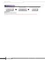
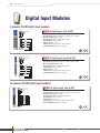
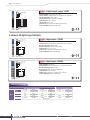
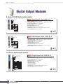
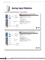
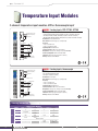
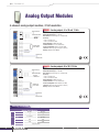
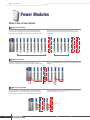
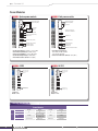
Remote I/O
NA-4020/4021
RS-232/485 (Modbus/RTU) network adaptors
ioLogik 4000
System Power (5 VDC)
System Power (GND)
Modbus RS-485
NA-4020
SYS
TxD
RxD
I/O
Field
Power
System Bus
Non-isolation
Switching
Power
00 11
24V 0V
CH0
System Power (0 VDC)
22 33
SG SG
Shielding Ground
4 5
0V 0V
CH0
Field Power (0 VDC)
66 77
24V CH0
24V
CH0
System Power (24 VDC)
Field Power (24 VDC)
Field Power (0 VDC)
Field Power (24 VDC)
Specifications
Serial Communication Parameters
Isolation
Parity: None, Even, Odd
Data Bits: 7, 8
Stop Bits: 1, 2
Baudrate: 1200 to 115200 bps
Signals:
• NA-4020: Data+, Data-, Gnd, DIR
• NA-4021: TxD, RxD, Gnd
System Power to I/O Driver: Optical isolation
Physical Characteristics
Dimensions: 45 x 99 x 70 mm (1.77 x 3.90 x 2.76 in)
Weight: 150 g
Environmental Limits
Operating Temperature: -10 to 60°C (14 to 140°F)
Storage Temperature: -40 to 85°C (-40 to 185°F)
Ambient Relative Humidity: 5 to 95% (non-condensing)
Software Features
Protocols: Modbus/RTU, Modbus/ASCII
Modbus Address: 00 to 99 (set by rotary switches)
Programming Library: MXIO DLL library for Windows; Supports
Visual Basic, Visual C++, Borland C++ Builder, .net, VB/VC.NET
Number of I/O Modules Supported: Max. of 32
Regulatory Approvals
Safety: UL508
EMC: CE IEC 61000-6-2, IEC 61000-6-4
Vibration: IEC-68-2-6 (2 g’s during operation)
Warranty
Power Requirements
Warranty Period: 2 years
Details: See www.moxa.com/warranty
Power Input: 11 to 28.8 VDC, 24 VDC typical
Power Consumption: 60 mA typical @ 24 VDC
Current for I/O Modules: Max. 1.5 A @ 5 VDC
Field Power
Rated Voltage: 11 to 28.8 VDC, 24 VDC typical
Current in Field Power Contact: Max. 10 A
Dimensions
I/O Network Adaptor
I/O Module
45.0 mm (1.8 in)
70.0 mm (2.8 in)
15.0 mm (0.6 in)
12.0 mm (0.5 in)
70.0 mm (2.8 in)
30.0 mm
(1.2 in)
1
70.0 mm (2.8 in)
Side View
99.0 mm (3.9 in)
99.0 mm (3.9 in)
99.0 mm (3.9 in)
99.0 mm (3.9 in)
60.0 mm (2.4 in)
60.0 mm (2.4 in)
Front View
Side View
Front View
Removable View
w w w. m o x a . c o m
[email protected]
Remote I/O
Ordering Information
Step 1: Select a network adaptor module
Step 2: Select I/O modules
Step 3: Select power modules (optional)
NA-4000 series
M-1000/2000/3000/4000/6000
series
M-7000 series
Available Models
NA-4020: RS-485 network adaptor (Modbus/RTU)
NA-4021: RS-232 network adaptor (Modbus/RTU)
Note: The NA-4020/4021 network adaptors can be expanded by adding up to 32 I/O modules. See below to select the M-series modules for your application.
2
w w w. m o x a . c o m
[email protected]
Remote I/O
I/O Module Selection Guide
I/O Modules
DC-Digital Inputs
Model
Channels
Specs
Sink/Source
Connector
Voltage
AC-Digital Inputs
M-1800
M-1801
M-1600
M-1601
M-1450
8
8
16
16
4
M-1451
4
Sink
Source
Sink
Source
–
–
RTB
RTB
20-pin
20-pin
RTB
RTB
24 VDC
24 VDC
24 VDC
24 VDC
110 VAC
220 VAC
Isolation
Optical isolation
Digital Outputs
Model
Channels
Sink/Source
Specs
Connector
M-2800
M-2801
M-2600
M-2601
8
8
16
16
M-2450
4
Sink
Source
Sink
Source
Relay
RTB
RTB
20-pin
20-pin
RTB
Voltage
24 VDC
24 VDC
24 VDC
24 VDC
24 VDC
Current
0.5 A
0.5 A
0.3 A
0.3 A
2.0 A
Isolation
Optical isolation
Analog Inputs
Model
M-3802
M-3810
M-6200
M-6201
8
8
2
2
Current
4 to 20 mA
–
–
–
Voltage
–
0 to 10 V
–
–
Connector
RTB
RTB
RTB
RTB
Resolution
12-bit
12-bit
–
–
RTD(ohm)
Thermo-couple
(mV)
Channels
Specs
Isolation
Optical isolation
Sensor
Input
–
–
Analog Outputs
Model
Channels
Specs
M-4402
M-4410
4
4
Current
4 to 20 mA
–
Voltage
–
0 to 10 V
Connector
RTB
RTB
Resolution
12-bit
12-bit
Isolation
Optical isolation
Power Modules
Power Modules
Model
M-7001
M-7002
M-7804
M-7805
0
0
8
8
Voltage
24 VDC
DC: 5, 24, 48 VDC
AC: 110/220 VAC
0 VDC
24 VDC
Purpose
System Power
Field Power
Field Power
Field Power
Channels
Specs
3
w w w. m o x a . c o m
[email protected]
Remote I/O
Digital Input Modules
8-channel 24 VDC digital input modules
M-1800
Status
0 4
System Power (5 VDC)
System Power (GND)
System Bus
1 5
2 6
3 7
0
1
CH0 CH1
2 3
CH2 CH3
4 5
CH4 CH5
6 7
CH6 CH7
Field Power (0 VDC)
Field Power (24 VDC)
M-1800: 8 digital inputs, sink, 24 VDC
Inputs per Module: 8 channels, sink type
On-state Voltage: 24 VDC nominal, min. 11 VDC to max. 28.8 VDC
Min. Off-state Voltage: Max. 5 VDC
On-state Current: Max. 6 mA/point @ 28.8 VDC
Input Impedance: Typ. 5.1K ohms
Filtering Time: Typ. 1.5 ms
Common Type: External common (single common)
Power Consumption: Max. 35 mA @ 5 VDC
Field Power (24 VDC)
Field Power (0 VDC)
M-1801
Status
0 4
1 5
System Power (5 VDC)
System Power (GND)
System Bus
2 6
3 7
0 1
CH0 CH1
2 3
CH2 CH3
4 5
CH4 CH5
6 7
CH6 CH7
M-1801: 8 digital inputs, source, 24 VDC
Inputs per Module: 8 channels, source type
On-state Voltage: 24 VDC nominal, min. 11 VDC to max. 28.8 VDC
Min. Off-state Voltage: Max. 5 VDC
On-state Current: Max. 6 mA/point @ 28.8 VDC
Input Impedance: Typ. 5.1K ohms
Filtering Time: Typ 1.5 ms
Common Type: External common (single common)
Power Consumption: Max. 35 mA @ 5 VDC
Field Power (0 VDC)
Field Power (24 VDC)
Field Power (24 VDC)
Field Power (0 VDC)
16-channel 24 VDC digital input modules
M-1600
Status
0 4 8 12
1 5 9 13
System Power (5 VDC)
System Power (GND)
System Bus
2 61014
3 71115
0
1
Ch0
1
2
3
4
5
6
7
8
9
10
11
12
13
14
15
0V
0V
M-1600: 16 digital inputs, sink, 24 VDC
Inputs per Module: 16 channels, sink type
On-state Voltage: 24 VDC nominal, min. 11 VDC to max. 28.8 VDC
Min. Off-state Voltage: Max. 5 VDC
On-state Current: Max. 6 mA/point @ 28.8 VDC
Input Impedance: Typ. 5.1K ohms
Filtering Time: Typ. 1.5 ms
Common Type: 16 channels for 2 COMs (single common)
Power Consumption: Max. 40 mA @ 5 VDC
24V 24V
18 19
4
Field Power (0 VDC)
Field Power (24 VDC)
w w w. m o x a . c o m
[email protected]
Remote I/O
M-1601
M-1601: 16 digital inputs, source, 24 VDC
System Power (5 VDC)
System Power (GND)
Status
0 4 8 12
Inputs per Module: 16 channels, source type
On-state Voltage: 24 VDC nominal, min. 11 VDC to max. 28.8 VDC
Min. Off-state Voltage: Max. 5 VDC
On-state Current: Max. 6 mA/point @ 28.8 VDC
Input Impedance: Typ. 5.1K ohms
Filtering Time: Typ. 1.5 ms
Common Type: 16 channels for 2 COMs (single common)
Power Consumption: Max. 40 mA @ 5 VDC
System Bus
1 5 9 13
2 61014
3 71115
0
1
Ch0
1
2
3
4
5
6
7
8
9
10
11
12
13
14
15
0V
0V
24V 24V
18 19
Field Power (0 VDC)
Field Power (24 VDC)
4-channel AC digital input modules
M-1450
M-1450: 4 digital inputs, 110 VAC
System Power (5 VDC)
System Power (GND)
Status
0
Inputs per Module: 4 channels
On-state Voltage: 120 VAC nominal, min. 85 VAC to max. 132 VAC
Min. Off-state Voltage: Max. 45 VAC
On-state Current: Max. 8 mA/point @ 132 VAC
Input Impedance: Typ. 11K ohms
Common Type: 4 channels for 2 COMs (single common)
Power Consumption: Max. 35 mA @ 5 VDC
System Bus
1
2
3
0 1
CH0 CH1
2 3
CH2 CH3
4 5
N N
6 7
L
L
Field Power (110 VAC N)
Field Power (110 VAC L)
* Field Power distributor required.
M-1451
M-1451: 4 digital inputs, 220 VAC
System Power (5 VDC)
System Power (GND)
Status
0
System Bus
1
Inputs per Module: 4 channels
On-state Voltage: 240 VAC nominal, min. 170 VAC to max. 264 VAC
Min. Off-state Voltage: Max. 45 VAC
On-state Current: Max. 12 mA/point @ 264 VAC
Input Impedance: Typ. 22K ohms
Common Type: 4 channels for 2 COMs (single common)
Power Consumption: Max. 35 mA @ 5 VDC
2
3
0 1
CH0 CH1
2 3
CH2 CH3
4 5
N N
6 7
L
L
Field Power (220 VAC)
Field Power (220 VAC N)
Field Power (220 VAC L)
* Field Power distributor required.
Ordering Information
DC-Digital Input Modules
Model
Channels
Specs
Sink/Source
Connector
Voltage
Isolation
5
AC-Digital Input Modules
M-1800
M-1801
M-1600
M-1601
M-1450
8
8
16
16
4
M-1451
4
Sink
Source
Sink
Source
–
–
RTB
RTB
20-pin
20-pin
RTB
RTB
24 VDC
24 VDC
24 VDC
24 VDC
110 VAC
220 VAC
Optical Isolation
w w w. m o x a . c o m
[email protected]
Remote I/O
Digital Output Modules
8-channel 24 VDC digital output modules
M-2800
M-2800: 8 digital outputs, sink, 24 VDC, 0.5 A
System Power (5 VDC)
System Power (GND)
Status
0 4
Outputs per Module: 8 channels, sink type
Output Voltage Range: 24 VDC nominal, min. 11 VDC to max. 28.8 VDC
On-state Voltage Drop: Max. 0.3 VDC @ 25°C
On-state Current: Min. 1 mA per channel
Off Leakage Current: Max. 50 µA
Output Current Rating: Max. 0.5 A per channel
Common Type: 8 channels per external common (single common)
Power Consumption: Max. 60 mA @ 5 VDC
System Bus
1 5
2 6
3 7
0 1
CH0 CH1
L
2 3
CH2 CH3
L
4 5
CH4 CH5
L
6 7
CH6 CH7
L
Field Power (0 VDC)
Field Power (24 VDC)
Field Power (24 VDC)
Field Power (0 VDC)
M-2801
M-2801: 8 digital outputs, source, 24 VDC, 0.5 A
System Power (5 VDC)
System Power (GND)
Status
0 4
Outputs per Module: 8 channels, source type
Output Voltage Range: 24 VDC nominal, min. 11 VDC to max. 28.8 VDC
On-state Voltage Drop: Max. 0.3 VDC @ 25°C
On-state Current: Min. 1 mA per channel
Off Leakage Current: Max. 50 µA
Output Current Rating: Max. 0.5 A per channel
Common Type: 8 channels per external common (single common)
Power Consumption: Max. 60 mA @ 5 VDC
System Bus
1 5
2 6
3 7
0 1
CH0 CH1
L
2 3
CH2 CH3
L
4 5
CH4 CH5
L
6 7
CH6 CH7
L
Field Power (0 VDC)
Field Power (24 VDC)
Field Power (24 VDC)
Field Power (0 VDC)
16-channel digital output modules
M-2600
Status
0 4 8 12
1 5 9 13
System Power (5 VDC)
System Power (GND)
System Bus
2 61014
3 71115
0
1
Ch0
1
L
2
3
L
4
5
L
6
7
L
8
9
L
10
11
L
12
13
L
14
15
L
0V
0V
M-2600: 16 digital outputs, sink, 24 VDC, 0.3 A
Outputs per Module: 16 channels, sink type
Output Voltage Range: 24 VDC nominal, min. 11 VDC to max. 28.8 VDC
On-state Voltage Drop: Max. 0.3 VDC @ 25°C
On-state Current: Min. 1 mA per channel
Off Leakage Current: Max. 50 µA
Output Current Rating:
• Max. 0.3 A per channel
• Max. 4 A per common
Common Type: 16 channels for 2 COMs (single common)
Power Consumption: Max. 80 mA @ 5 VDC
24V 24V
18 19
6
Field Power (0 VDC)
Field Power (24 VDC)
w w w. m o x a . c o m
[email protected]
Remote I/O
M-2601
Status
0 4 8 12
1 5 9 13
M-2601: 16 digital outputs, source, 24 VDC, 0.3 A
System Power (5 VDC)
System Power (GND)
Outputs per Module: 16 channels, source type
Output Voltage Range: 24 VDC nominal, min. 11 VDC to max. 28.8 VDC
On-state Voltage Drop: Max. 0.3 VDC @ 25°C
On-state Current: Min. 1 mA per channel
Off Leakage Current: Max. 50 µA
Output Current Rating:
• Max. 0.3 A per channel
• Max. 4 A per common
Common Type: 16 channels for 2 COMs (single common)
Power Consumption: Max. 80 mA @ 5 VDC
System Bus
61014
71115
0
1
Ch0
1
L
2
3
L
4
5
L
6
7
L
8
9
L
10
11
L
12
13
L
14
15
L
0V
0V
24V 24V
18 19
Field Power (0 VDC)
Field Power (24 VDC)
4-channel relay output modules
M-2450: 4 relay outputs, 24-VDC/230-VAC, 2 A
Outputs per Module: 4 channels, relay
Relay Type:
• Form A, Normally Open (N.O.)
• Single Pole, Single Throw (SPST)
Output Voltage Range: Load dependent
• 5 to 28.8 VDC @ 2 A resistive
• 48 VDC @ 0.8 A resistive
• 110 VDC @ 0.3 A resistive
• 250 VAC @ 2 A resistive
Output Current Rating: At rated power
• 2 A @ 5 to 28.8 VDC
• 0.8 A @ 48 VDC
• 0.5 A @ 110 VDC
• 2 A @ 250 VAC
Min. Load: 100 µA, 100 m VDC per point
Max. On-state Voltage Drop: 0.5 V @ 2 A, resistive load, 24 VDC
Off-state Leakage Current: Max. 1.5 mA
Common Type: 1 channel for 1 COM
Power Consumption: Max. 65 mA @ 5 VDC
Ordering Information
Digital Output Modules
Model
M-2800
M-2801
M-2600
M-2601
8
8
16
16
4
Sink/Source
Sink
Source
Sink
Source
Relay
Connector
RTB
RTB
20-pin
20-pin
RTB
24 VDC
24 VDC
230 VAC/
24 VDC
0.3 A
0.3 A
2.0 A
–
–
Channels
Specs
Voltage
24 VDC
24 VDC
Current
0.5 A
0.5 A
Isolation
Diagnostics
7
M-2450
Optical isolation
–
–
–
w w w. m o x a . c o m
[email protected]
Remote I/O
Analog Input Modules
8-channel analog input modules, 12-bit resolution
M-3802: 8 analog inputs, 4 to 20 mA, 12 bits
M-3802
M-3802
Status
Status
System
System
Bus Bus
Resolution in Ranges: 12 bits, 3.91 µA/bit
Input Current Range: 4 to 20 mA (single-ended)
Data Format: 16-bit integer (2’s complement)
Accuracy:
• ±0.1%, FSR @ 25°C
• ±0.3%, FSR @ 0°C, 60°C
Input Impedance: 120 ohms
Conversion Time: 4 ms for all channels
Power Consumption: Max. 150 mA @ 5 VDC
Isolation: I/O to logic (photocoupler isolation)
Wiring: I/O cable max. AWG14
M-3810: 8 analog inputs, 0 to 10 V, 12 bits
M-3810
Status
System Bus
8
Resolution in Ranges: 12 bits, 2.44 mV/bit
Input Current Range: 0 to 10 VDC (single-ended)
Data Format: 16-bit integer (2’s complement)
Accuracy:
• ±0.1%, FSR @ 25°C
• ±0.3%, FSR @ 0°C, 60°C
Input Impedance: 500K ohms
Conversion Time: 4 ms for all channels
Power Consumption: Max. 150 mA @ 5 VDC
Isolation: I/O to logic (photocoupler isolation)
Wiring: I/O cable max. AWG14
w w w. m o x a . c o m
[email protected]
Remote I/O
Temperature Input Modules
2-channel temperature input modules, RTD or thermocouple input
M-6200: 2 analog inputs, RTD: PT100, JPT100
M-6200
Sensor Types:
• PT50, PT100, PT200, PT500, PT1000 (resistance 100 milli-ohms/bit)
• JPT100, JPT200, JPT500, JPT1000 (resistance 10 milli-ohms/bit)
• NI100, NI200, NI500, NI1000, NI120, CU10 (resistance 20 milli-ohms/bit)
Resolution: 0.1°C/10 milli-ohms
Data Format: 16-bit integer (2’s complement)
Accuracy:
• ±0.1%, FSR @ 25°C
• ±0.3%, FSR @ 0°C, 60°C
Input Impedance: 500K ohms
Conversion Time: 200 ms for all channels
Diagnostics: Range over (if range over, data=Dx8000)
Power Consumption: Max. 80 mA @ 5 VDC
Isolation: I/O to logic (photocoupler isolation)
Wiring: I/O cable max. AWG14
System Power (5 VDC)
System Power (GND)
Status
0
System Bus
1
0 1
CH0 CH1
CH1-A
RTD
2 3
CH1-B
CH0 CH1
4 5
G G
6 7
CG CG
Shielding Ground
Field Power (0 VDC)
Field Power (24 VDC)
M-6201: 2 analog inputs, thermocouple
M-6201
System Power (5 VDC)
System Power (GND)
Status
0
Sensor Types:
Type J/K/T/E/R/S/B/N/L/U/C/D
(mV input 10 µV/bit, 2 µV/bit)
Resolution: 0.1°C/10 µV
Data Format: 16-bit integer (2’s complement)
Accuracy:
• ±0.1%, FSR @ 25°C
• ±0.3%, FSR @ 0°C, 60°C
Input Impedance: 500K ohms
Conversion Time: 200 ms for all channels
Diagnostics: Range over (if range over, data=Dx8000)
Power Consumption: Max. 80 mA @ 5 VDC
Isolation: I/O to logic (photocoupler isolation)
Wiring: I/O cable max. AWG14
System Bus
1
Voltage 0 to 10V
0 1
CH0 CH1
2 3
CH0 CH1
Thermocouple
CH1+
CH1-
4 5
G G
6 7
CG CG
Shielding Ground
Field Power (0 VDC)
Field Power (24 VDC)
Ordering Information
Analog Input Modules
Model
M-3802
M-3810
M-6200
M-6201
8
8
2
2
Current
4 to 20 mA
–
–
–
Voltage
–
0 to 10 V
–
–
Channels
Specs
Connector
RTB
RTB
RTB
RTB
Resolution
12-bit
12-bit
–
–
RTD
(ohm)
Thermo-couple
(mV)
Isolation
Sensor
Input
9
Optical isolation
–
–
w w w. m o x a . c o m
[email protected]
Remote I/O
Analog Output Modules
4-channel analog output modules, 12-bit resolution
M-4402: 4 analog outputs, 4 to 20 mA, 12 bits
M-4402
Resolution in Ranges: 12 bits, 3.91 µA/bit
Output Current Range: 4 to 20 mA
Data Format: 16-bit integer (2’s complement)
Accuracy:
• ±0.1%, FSR @ 25°C
• ±0.3%, FSR @ 0°C, 60°C
Output Impedance: Max. 500 ohms
Conversion Time: 2 ms for all channels
Power Consumption: Max. 65 mA @ 5 VDC
Isolation: I/O to logic (photocoupler isolation)
Wiring: I/O cable max. AWG14
Status
System Bus
M-4410: 4 analog outputs, 0 to 10 V, 12 bits
Resolution in Ranges: 12 bits, 2.44 mV/bit
Output Current Range: 0 to 10 VDC
Data Format: 16-bit integer (2’s complement)
Accuracy:
• ±0.1%, FSR @ 25°C
• ±0.3%, FSR @ 0°C, 60°C
Output Impedance: Max. 5K ohms
Conversion Time: 2 ms for all channels
Power Consumption: Max. 200 mA @ 5 VDC
Isolation: I/O to logic (photocoupler isolation)
Wiring: I/O cable max. AWG14
M-4410
Status
System Bus
Ordering Information
Analog Output Modules
Model
Channels
Specs
M-4410
4
4
Current
4 to 20 mA
–
Voltage
–
0 to 10 V
Connector
RTB
RTB
Resolution
12-bit
12-bit
Isolation
10
M-4402
Optical Isolation
w w w. m o x a . c o m
[email protected]
Remote I/O
Power Modules
When to Use a Power Module
System Power Distributor
The system power expansion module is designed to provide extra
power for connected I/O expansion modules. Each NA-4000 series
network adaptor can provide 1.5 A @ 5 VDC. If you need more power
for your installed I/O expansion modules, you will need to use an
M-7001 module. However, note that the M-7001 can only provide
1 A @ 5 VDC.
M-7001
...................
150 mA
150 mA
150 mA
150 mA
150 mA
150 mA
150 mA
200 mA
Supports 1000 mA
150 mA
200 mA
200 mA
Total: 1400 mA
200 mA
200 mA
200 mA
Supports 1000 mA
Supports 1000 mA
Total: 1000 mA
Field Power Distributor
The field power distributor is designed to isolate different field
voltages. For example, before you connect a 48 VDC or 110 VAC DI/O
module to a 24 VDC DI/O module, you will need an M-7002 field power
distributor.
M-7002
M-7002
24 VDC
0V
48 VDC
24V
0V
48V
110 VAC
0V
110 VAC
Potential Power Distributor
There are three types of potential distributor modules that provide
extra wiring points, such as shielding ground, 0 V field power, and
24 V field power. For example, the 8-channel digital input (sink type)
M-1801
M-7804
module by itself does not have a 24 V wiring point. In this case, you
can add an M-7805 for easier wiring.
M-1800
M-7805
...................
8-ch , 0 VDC
11
8-ch , 24 VDC
w w w. m o x a . c o m
[email protected]
Remote I/O
Power Modules
M-7001: System power module
M-7001
M-7002: Field power module
M-7002
System Power (5 VDC)
System Power (GND)
System Power (5 VDC)
System Power (GND)
System Bus
System Bus
Non-isolation
Switching
Power
*Field Power ranging from
24/48 VDC to 110/220 VAC
0 1
0 1
System Power Input (0 VDC)
24V 0V
System Power Input (24 VDC)
2 3
CG CG
2 3
CG CG
Shield Ground
Shield Ground
4 5
0V 0V
Field Power Input (0 VDC)
4 5
N N
Field Power Input (N)
6 7
24V 24V
Field Power Input (24 VDC)
6 7
P
P
Field Power Input (P)
Field Power (N)
Field Power (P)
Field Power (0 VDC)
Field Power (24 VDC)
*Field Power contact disconnected
• System Input Voltage: 24 VDC, 11 to 28.8 VDC
• Field Power Input Voltage: 24 VDC (±20%)
• Current for I/O Modules: 1 A @ 5 VDC (Max.)
• System Bus Output Voltage: 5 VDC (Max.)
• Field Power Contacts Current: 10 A (Max.)
• Field Power Input Voltage:
DC: 5 VDC, 24 VDC, 48 VDC
AC: 110 VAC, 220 VAC
• Current for Field Power Contacts: 10 A (Max.)
M-7804: 0 VDC
M-7805: 24 VDC
M-7804
M-7805
System Power (5 VDC)
System Power (GND)
System Power (5 VDC)
System Power (GND)
System Bus
System Bus
0 1
0V
0 1
0V
24V 24V
2 3
0V 0V
2 3
24V 24V
4 5
0V 0V
4 5
24V 24V
6 7
0V 0V
6 7
24V 24V
Field Power (0 VDC)
Field Power (24 VDC)
Field Power (0 VDC)
Field Power (24 VDC)
Channels: 8
Mode: 0 VDC
Channels: 8
Mode: 24 VDC
Ordering Information
Power Modules
Model
M-7002
M-7804
M-7805
0
0
8
8
Voltage
24 VDC
DC: 5, 24, 48 VDC
AC: 110/220 VAC
0 VDC
24 VDC
Purpose
System Power
Field Power
Field Power
Field Power
Channels
Specs
12
M-7001
w w w. m o x a . c o m
[email protected]
Remote I/O
Modular I/O Accessories
TB 1600 DIN-Rail mounting screw terminal module with 20-pin connector
•
•
•
•
•
20 pins, one-to-one assignment
Connector pitch: 3.81 mm
DIN-Rail mounting type
Dimensions: 77.5 x 67.5 x 51 mm (3.05 x 2.66 x 2.01 in)
RoHS compliant
20-to-20-pin flat cable
• Connects between the TB 1600 and ioLogik 4000 series
• Length: 500 mm
• Number of Pins: 20
M-8001-PK Removable terminal block
• Terminal block for the ioLogik 4000 series
• Packaging: 9 pcs in one box
M-8003-PK Marker with 0 to 9 numbering
M-8004-PK Blank marker
• Marker for the ioLogik 4000 series
• Packaging: 100 pcs in one box
Ordering Information
•
•
•
•
•
13
TB 1600: DIN-Rail mounting screw terminal module with 20-pin connector
20-to-20-pin flate cable: 20-pin to 20-pin flat cable, 500 mm
M-8001-PK: Removable terminal block, 9 pcs per pack
M-8003-PK: Marker with 0 to 9 numbering, white color, 100 pcs
M-8004-PK: Blank marker, 100 pcs
© Moxa Inc. All Rights Reserved. Updated Mar. 17, 2010. Specifications subject to change without notice. Please visit our website for the most up-to-date product information.