1
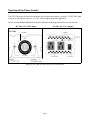
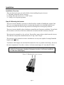
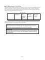
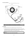
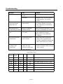
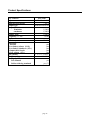
Smooth Start Series
User Instructions for
Model STP-1500 Power Inverter
Model STP-1500
Safety Information
IMPORTANT
Read all the Cautions and Warnings before installing and using the power inverter. The
inverter must be properly installed.
IMPORTANT
If you are not familiar with 12 volt high current wiring, it is recommended that you have a
professional automotive installer install the inverter.
CAUTION
The power inverter generates 115 VAC power from your 12 volt car battery. Treat the 115
VAC output just like you treat the 115 VAC in your house. Keep children away from the
unit.
Do not connect the unit to AC distribution wiring.
Keep the unit away from water. Do not allow water to drip or splash on to the power inverter.
Keep the unit in cool environments. Ambient air temperature should be between 32 degrees and
75 degrees F. Keep out of direct sunlight and away from heating vents.
Keep the unit away from flammable material or in any location which may accumulate flammable
fumes or gases, such as the battery compartment of your car, boat, RV or truck.
With heavy use, the unit will become warm and possibly hot. So keep it away from any heat
sensitive materials.
Make sure the opening to the fan and vent holes are not blocked.
Do not open the unit. High voltages are inside.
Use proper size wiring. High power inverters can draw many amps from the 12 volt source and
can melt wires if not fused and sized properly.
IMPORTANT
Sima Products Corporation does not authorize any products to be used in life support
devices or systems.
Serial # ___________________
Date Purchased ___________
page 2
Table of Contents
Safety Information ...................................................................................................2
Introduction..............................................................................................................4
Key Features ............................................................................................................4
Package Includes......................................................................................................4
Needed for Installation (not included) .....................................................................4
Overview of the Power Inverter...............................................................................5
Installation ...............................................................................................................6
Installation Overview ....................................................................................................................6
Step #1: Mounting the Inverter .....................................................................................................6
Step #2: Wiring Inverter to 12 volt Power ....................................................................................7
Permanent Installation...............................................................................................................8
Wiring Steps..............................................................................................................................8
Advanced Installation................................................................................................................9
Step #3: Testing the Power Inverter ..............................................................................................9
Operation ...............................................................................................................10
Equipment Power Usage .............................................................................................................10
Battery Life .................................................................................................................................10
Lights and Alarms .......................................................................................................................11
How the Inverter Works.........................................................................................12
Troubleshooting .....................................................................................................13
Product Specifications ...........................................................................................14
Warranty ................................................................................................................15
page 3
Introduction
Congratulations on your purchase of a Sima Products Corporation power inverter. It provides 115
VAC anywhere you have 12 DC volts in your car, truck, RV or boat. It is designed to be easy to use
and provide years of dependable service.
Key Features
High-efficiency operation to provide the most output with the least battery power.
Advanced protection
• Thermal Protection shuts the unit off to guard against the unit getting too hot
• Overload Protection protects the unit from excessive loads
• Under Voltage Protection turns the unit off to protect the battery from being over
discharged
The STP-1500 power inverter produces a modified sine wave output that is suitable for most AC loads.
This includes lights, appliances, motors, TVs and most electronics.
Caution: A few battery chargers are not compatible with modified sine wave
operation. These are typically small, rechargeable, battery operated devices like
razors and flashlights that can be plugged directly into an AC receptacle to
recharge. Some chargers for battery packs used in power tools also should not be
used with an inverter. These chargers typically have a warning label indicating
that dangerous voltages are present at the battery terminals. Only a true sine
wave inverter should be used with these types of appliances. Damage to the
device could result if you attempt to use them with any type of modified sine wave
inverter. Do not use this power inverter with the above devices.
Package Includes
Inverter (STP-1500)
Cables with ring terminals
This manual
Needed for Installation (not included)
Mounting hardware for the inverter
12 volt DC power wiring, fuse block and connectors
Tools – Drill and drill bit, small socket set, wire crimpers, volt meter
Optional: wiring kit from Sima (SK-200)
page 4
Overview of the Power Inverter
The STP-1500 power inverters are electronic devices that convert the low voltage 12 VOLTS DC from
a battery or other power source to 115 VAC to run standard household appliances.
See the section on How it Works to learn more about the technology used in these power inverters.
DC Side (12 VOLTS Input)
AC Side (115 VAC Output)
STP-1500
Figure #1, DC and AC Sides of the STP-1500 Inverter
page 5
Installation
Installation Overview
There are three basic steps you need to follow when installing the power inverter.
1) Mounting: Mount the inverter securely
2) Wiring: Wire the inverter to a 12 VOLT source
3) Testing: Test for proper operation
Step #1: Mounting the Inverter
The power inverter should be secured to a solid flat surface capable of handling the weight of the
unit. It is very important that the unit be secured using the proper size mounting hardware (not
included) to keep the unit from moving around or becoming loose in emergency situations.
The power inverter should be placed with space around the unit for proper ventilation. Do not block
the air entrance to the fan or block the exhaust holes located on the side or bottom of the unit.
The unit must be mounted in a dry, cool area. Do not allow water to drip or splash onto the inverter.
The ambient air temperature should be between 32 deg F and 75 deg F.
The unit must not be mounted in an area with batteries or in any area capable of storing flammable
liquids such as gasoline.
To minimize cable lengths, the unit should be mounted as close as possible to the battery, but not in
the same compartment. If you have a choice, it is better to run longer AC wires than DC cables.
Caution: The power inverter must be mounted securely in any type of moving
vehicle. In an emergency situation, if the power inverter is not securely mounted,
it could cause bodily injury
Figure 2, Mounting the power inverter
page 6
Step #2: Wiring Inverter to 12 volt Power
The power inverter requires connection to a standard 12 volt DC power source as found in most cars,
trucks, RVs and boats. The power source must provide between 11 and 15 volts DC. The power
source must be able to provide sufficient current to power the load. See the chart below that shows
minimal wire sizing and current draw at full load.
Inverter Model
STP-1500
Wire Size Chart
Current at
Suggested
Suggested
Suggested
rated power
User
Wire gauge,
Wire gauge,
Installed 12 less than-10’
10’ to 25’
volt Fuse
Size
140 Amps
150A
2 AWG
0 AWG
Always connect the positive, red (+) terminal to the positive connection and the negative, black (-)
terminal to the negative or ground side of the power system.
WARNING
Failure to connect the correct polarity may cause damage to the power inverter
and/or your electrical system and is not covered by the warranty.
Installation Tip
To minimize electrical interference, keep the DC power cables as short as possible
and twist them with 1 to 3 twists per foot. This minimizes radiated interference
from the cables.
page 7
Permanent Installation
Figure 3, Wiring the STP-1500 power inverter
Caution: Always use adequate wire size and fusing for any installation
Wiring Steps
• Disconnect the positive battery terminal before doing any wiring to the inverter.
•
Using proper sized copper wire and proper terminations, wire the inverter to the electrical
system and fuse block. See your local RV dealer or automotive shop for wire, connectors, fuse
block and other wiring parts. Tighten all connections firmly, but do not over tighten.
Remember to recheck all connections every few months of operation.
WARNING
Do not operate the power inverter without a fuse installed.
page 8
•
Double check all wiring for proper polarity.
•
Install the fuse and reconnect the wire to the battery. Note, a slight spark and beep from the
inverter is normal when the unit is first connected to 12 volt power.
Advanced Installation
Large inverters can draw high currents from your battery and charging system especially when used
with appliances and tools that use a lot of power. In these applications, you may need to increase the
capacity of your 12 volt system. There are several ways to do this.
High Capacity Batteries
You can purchase high capacity batteries that are specially designed for deep discharge operation.
Contact your automotive or RV specialist for more information.
Multiple Batteries
In systems with more than one battery, you typically wire the system with the batteries in parallel
(negative to negative and positive to positive) with a battery isolator between the positive
terminals. The isolator allows a single alternator to charge all batteries but lets the inverter only
use the second battery so the vehicle’s battery is not discharged during operation. Contact your
automotive or RV specialist for more information about battery isolators and wiring.
Larger Alternator
Typical automotive alternators may not be able to supply the power required for continuous
operation of the inverter at high power usage. Contact your automotive or RV specialist for more
information about larger output alternators.
Step #3: Testing the Power Inverter
After you make sure the 12 volt power is wired properly to the power inverter, with nothing plugged
into the 115 VAC outlets, turn the power switch on the power inverter to On. The green POWER
light will light.
Note: If the inverter does not operate properly and the POWER light does not illuminate, turn the
power switch off and check your wiring and external fuse.
With the inverter turned off, plug the appliance you want to use into the 115 VAC power outlet on
the unit. Turn the power switch on the power inverter on so the green POWER light is illuminated.
Turn on the appliance. The appliance should now be operational.
Check the Troubleshooting section if you have any difficulties.
page 9
Operation
Equipment Power Usage
It is important to use only products that draw less than the power rating of the power inverter. Use of
products greater than the rated power rating may either cause the protection circuitry of the power
inverter to shut down or the fuse to blow. Repeated use of excessive power draw can cause failure of
the power inverter.
How to calculate power usage. Most products have a power rating on them such as 45 watts. Others
may be marked with their current draw, such as .9 amps. To convert the current to watts multiply the
current by 115. (Example: .9 amps x 115 = 104 watts)
Typical Power Usage Chart
Typical Appliance
VCR/TV combo
19” TV
Small power drill 3/8”
Blender
Toaster
Vacuum
Small microwave oven
Hair Dryer
Space Heater
Current Draw
120 watts
160 watts
500 watts
650 watts
850 watts
900 watts
1100 watts
1200 watts
1300 watts
Some products draw a high surge current to start up. If the appliance does not operate and the
inverter turns off, you may need a larger inverter. Also, check that the battery and the 12 volt wiring
to the inverter is large enough to handle the current draw and that the battery is fully charged.
Important: The power inverters may not operate some appliances designed to produce
heat such as hair dryers, heaters, toasters and coffee makers. Always check the power
rating before using these kinds of products to be sure they do not exceed the power
capability of the inverter.
Battery Life
Important: The power inverter can draw lots of amps from your car’s battery when operating. If you
are using it for extended periods of time, you will want to operate your car occasionally to maintain
the charge in your car’s battery. In addition, the power inverter will also draw a small current, less
than 0.1 amp, when turned off and not operating. Therefore, it should be disconnected from your
car’s battery if your vehicle will not be used for more than a day. The following chart shows typical
operation time for typical car batteries with the engine not running for various loads. Check the size
of your battery.
page 10
Power
Usage
100 watt
200 watt
500 watt
Battery Life Chart
Approximate
Typical operation time
12 volt
with 50 amp-hour car
Current
battery
9 Amps
5.5 hours
19 Amps
2.6 hours
47 Amps
1 hour
Typical operation
time with 100 amphour car battery
11 hours
5.2 hours
2 hours
Actual Current Draw
Approximate 12 volt current draw is the load in watts divided by 10. Thus a 60 watt light bulb
plugged into the inverter will cause the inverter to draw 6 amps (60 / 10 = 6) from the 12 volt
supply.
Batteries are rated in several different ways:
Peak cranking amps - This has little to do with how long an inverter can supply power, so it
is not a useful number for inverter operation.
Battery reserve capacity - This number shows how long a battery can supply a given current,
typically 25 amps, before the battery voltage reaches a low voltage. Therefore, a battery
rated at 200 minutes reserve can deliver 25 amps for 200 minutes before it is discharged.
Ampere-hour capacity - This rating indicates how many amps a battery can deliver over a
period of time, typically 20 hours. Therefore, a 100 amp-hour battery can deliver 5 amps
for 20 hours (5 x 20 = 100).
Actual operating time from a battery will depend upon the current draw from the battery. A
battery will deliver less total power (energy) as you draw higher amps. A 100 amp-hour
battery can deliver 5 amps for 20 hours (100 amp-hours) but it will only deliver 50 amps
for 1 ½ hours (50 x 1.5 = 75) or 75 amp-hours at the higher rate.
Also remember, battery life is decreased if the battery is discharged fully. Lead acid
batteries have the longest life, if they are kept fully charged.
Lights and Alarms
POWER Indicator (Green)
This light will illuminate when the inverter is turned on and is operating normally. If this light goes
out the 12 volt power is missing (possible blown fuse). These fault conditions include output
overload, output short circuit, low input voltage and over temperature of the unit. This can happen if
a device has a large turn on surge, if an appliance (like a drill or saw) is stalled or if the inverter does
not have a supply of cool air.
Fault Indicator (Red) Fault conditions include output overload, output short circuit, low input
voltage and over temperature of the unit. This can happen if a device has a large turn on surge, if an
appliance (like a drill or saw) is stalled or if the inverter does not have a supply of cool air.
Fuse Replacement
If you overload the power inverter, it is possible that the external fuse might blow. Always determine
the cause of the fuse blowing and remedy the problem before using the power inverter again.
page 11
How the Inverter Works
The Sima Products Corporation power inverter has two electronic sections. The first section converts
12 volts DC to approximately 160 volts DC using modern high frequency conversion techniques that
uses small lightweight efficient transformers. The second section converts the 160 volts DC to 115
VAC using high efficiency power MOSFET transistor devices. The inverters generate a modified sine
wave that works with almost every product on the market.
CAUTION: Do not use the following products with an inverter with a modified sine
wave output.
Small battery operated devices like razors, flashlights and night lights that can be
plugged directly into an AC outlet to recharge
A few battery chargers for power tool battery packs that have warnings about high
voltage present on the battery terminals.
Smooth Start
The Smooth Start feature of the STP line of power inverters is designed to handle the power surge that
is created when some appliances are turned on. This feature helps protect both the appliance and the
inverter from excessive power draws and surges.
When the power switch is turned on, the STP inverter smoothly brings up the AC power. This circuitry
also activates under excessive loads, even short circuits, to quickly turn off power to protect the device
and the inverter. The STP inverter then attempts to smoothly bring up the AC power, unless it detects
an excessive load.
page 12
Troubleshooting
Problem
Unit does not operate
Unit operates for a
short period and
then turns off
Cause
Input voltage is below
10 volts
Fuse blown
Load is trying to draw too
much current
Unit operates for a
Inverter is in thermal
while and gets warm
shutdown mode
Low battery alarm is
Input voltage is below
on
10.2 volts
Television and stereo
interference
RF interference from
power inverter
115 VAC Output
voltage reads
incorrectly
Modified sine wave
output can cause
incorrect reading on a
typical multimeter
Solution
Attach to proper supply
Determine cause for fuse blowing
and then replace fuse feeding
inverter.
Be sure load is less than rated watts
of inverter. Remove excessive
load. Turn inverter off and back
on to reset.
Allow inverter to cool down. Turn
inverter off and back on to reset.
Make sure car engine is running.
Check condition of wiring.
Battery may be low and needs
recharging.
Position the power inverter and
wiring as far as possible from
electronic equipment, antenna and
cables and reorient as necessary.
Use a true RMS meter like a Fluke
8060A or Triplett 4200 to measure
correct voltage.
Light Status Chart
Power
Switch
Power
Light
Beeper
Fan
Fault Light
Off
Off
Off
Off
Off
Unit is off
On
On
Off
On
Off
Normal Operation
On
On
On
On
Off
Low input voltage, 10.2 to 9.7 volts
On
On
On
On
On
Low input voltage, less than 9.7 volts
On
On
Off
On
On
High Input voltage, greater than 15V
On
On
Off
On
On
Unit over temperature or overloaded
On
Off
Off
Off
Off
No 12 VOLTS input to inverter
page 13
Mode
Product Specifications
Key Features
Input
Input no-load current
Output type
Output, Watts,
10 minutes
continuous
Output, peak
Frequency, +/- 1%
Outlets
Efficiency
Protection
Thermal
Low battery alarm (10.2v)
Low battery shutdown (9.5v)
Output short circuit
Over voltage (15v)
Size (inches)
Weight: unit/gross
Package Includes:
User Manual
Cables with ring terminals
STP-1500
12 - 15 volts DC
< 0.8 A
modified sine wave
1,500W
1,200W
3,000W
60 Hz
2
85-90%
yes
yes
yes
yes
yes
3” x 4.75” x 16.25”
8.6 / 12 lb
yes
yes (5’)
page 14
Limited Warranty
Sima Products Corporation (“Company”) warrants that if the accompanying product proves to be defective to
the original purchaser in material or workmanship within 90 days from the original retail purchase, the
Company will, at the Company’s option, either repair or replace same without charge (but no cash refund
will be made). If the product is returned within three (3) years from the original date of purchase, the
Company will repair or replace the unit, however, a standardized labor-only fee will be charged. The
Company will not charge a fee for any parts used in the repair. The Company will notify you of any fees to
be assessed prior to servicing the unit.
What you must do to enforce the Warranty: You must deliver, mail or ship the product, together with the
original bill of sale, this limited Warranty statement as proof of warranty coverage to:
Sima Products Corporation
Attn: Customer Service
140 Pennsylvania Ave., Bldg. #5,
Oakmont, PA 15139
Call customer service (800-345-7462) before sending the unit in for service.
Limitation of Liability and Remedies
Sima Products Corporation shall have no liability for any damages due to lost profits, loss of use or
anticipated benefits, or other incidental, consequential, special or punitive damages arising from the use of,
or the inability to use, this product, whether arising out of contract, negligence, tort or under any warranty,
even if Sima Products Corporation has been advised of the possibility of such damages. Sima Products
Corporation’s liability for damages in no event shall exceed the amount paid for this product. Sima Products
Corporation neither assumes nor authorizes anyone to assume for it any other liabilities.
Sima Products Corporation
140 Pennsylvania Ave
Bldg #5
Oakmont, PA 15139 USA
800-345-7462
Sima Products Corporation ©2003
P/N #21688
page 15

![User Manual [PDF 1.83MB]](http://vs1.manualzilla.com/store/data/005708072_1-847484e89010f626b2bba7bc797371fb-150x150.png)