1
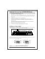
EN
FCC COMPLIANCE STATEMENT
Note: This equipment has been tested and found to comply with the limits for a
Class B digital device, pursuant to Part 15 of the FCC Rules. These limits are
designed to provide reasonable protection against harmful interference in a
residential installation. This equipment generates, uses, and can radiate radio
frequency energy and, if not installed and used in accordance with the instructions,
may cause harmful interference to radio communications. However, there is no
guarantee that interference will not occur in a particular installation. If this
equipment does cause harmful interference to radio or television reception, which
can be determined by turning the equipment off and on, the user is encouraged to try
to correct the interference by one of the following measures:
- Reorient or relocate the receiving antenna.
- Increase the separation between the equipment and receiver.
- Connect the equipment into an outlet on a circuit different from that to which
the receiver is connected.
- Consult the dealer or an experienced radio/TV technician for help.
FCC Caution: To assure continued compliance, (example – use only shielded
interface cables when connecting to computer or peripheral devices). Any changes
or modifications not expressly approved by the party responsible for compliance
could void the user’s authority to operate this equipment.
This device complies with Part 15 of the FCC Rules. Operation is subject to the following two
conditions: (1) this device may not cause harmful interference, and (2) this device must accept
any interference received, including interference that may cause undesired operation.
Acknowledgment & Trademark
All contents are subject to change at any time without notice. No responsibility is assumed for
its use; nor for infringements of patents or other rights of third parties and no patent or license
is implied hereby.
All trademarks are the property of their respective owners.
Safety Notice
1.
2.
3.
4.
5.
Do not install or operate the product in high temperature, humidity or dusty environment.
Do not attempt to open the cover to repair the product yourself.
Never spill liquid of any kind on the product.
Always follow instructions on this manual under operating the product.
To prevent exposure to laser emanations(harmful to human eyes), do not attempt to
disassemble this unit.
6. Hold CD discs by their edges. Do not touch the surface of the discs.
7. The drive is designed to be incorporated into a computer-based system or unit which has an
enclosing cover. Using the drive alone or in any other configuration is prohibited.
Caution: Use of controls or adjustments or performance of procedures other than those
specified herein may result in hazardous radiation exposure.
ENGLISH
INTRODUCTION
Thanks you for your purchasing this DVD-ROM drive.
Please read this manual before using the drive in order to take you step-by-step through the
process of setting up and installing the DVD-ROM drive.
Precautions
•
Do not attempt to open the drive and service it. Removing the cover may cause exposure
to harmful laser beam and electrical voltage. User is recommended to get service by
returning the defected drive back to the original vendor where the drive is purchased.
•
Use the original packing for transporting the drive or sending back for service. The
original packing were designed and tested to protect your drive under rough condition.
•
Do not put this DVD-ROM drive in direct sunlight, on heat units, or near electrical
appliances which draw large amounts of current.
•
Keep your disc clean. Using soft, dust-free cloth to clear the surface of the disc.
•
Do not drop or jolt the drive.
•
Keep the area around the DVD-ROM drive clean from dust, smoke, and other
contaminants.
•
Do not use fragile disc, it may crack during high speed reading.
System Requirements
To ensure stable performance, an IBM compatible PC system with following features is
recommended.
For ATAPI/E-IDE Drives:
CPU
: Pentium 4 1.3GHz or higher
OS
: Windows 98SE/2000/ME/XP
Memory
: 128MB minimum
Hard Drive
: Minimum 650MB available capacity
Interface
: Vacant IDE interface connector
For Serial ATA Drives:
CPU
OS
Memory
Hard Drive
Interface
:
:
:
:
:
Pentium 4 1.3GHz or higher
Windows 2000/XP
256MB minimum
Minimum 650MB available capacity
Vacant Serial ATA interface connector
Software
The DVD software packed is to give you the best result with the ease of use.
Note: We recommend you to refer system requirement from DVD software manual when
playing DVD movie by software.
1
ENGLISH
HARDWARE INSTALLATION OF ATAPI/E-IDE DRIVES
1.
2.
3.
4.
5.
6.
7.
8.
9.
Turn off PC and disconnect all power cords.
Remove the PC cover from computer.
Set the Master/Slave jumper on DVD-ROM rear panel according to the following section.
Find an empty bay, slide the DVD-ROM into the bay horizontally and mount the drive
with 4 screws.
Connect the power supply cable to DVD-ROM drive.
Ensure the pin definition of power connector is the same as shown in figure 1.
Connect the 40-pin E-IDE cable to DVD-ROM according to the description in the
following section.
Connect the sound cable from the Analog Audio on the rear panel of DVD-ROM to
sound card if you have a sound card in your system.
Put the PC cover back and connect the power cords.
Connect the power cord to an AC outlet and turn on computer.
Set Master or Slave Jumper
There are three pairs of jumpers, MA(Master), SL(Slave) and CS(CSEL) on the rear panel of
your DVD-ROM drive. Figure 1 shows the location of the jumper.
CABLE SELECT
SLAVE
MASTER
DIGITAL ANALOG
AUDIO AUDIO
DG
RGGL
C S M
S L A
POWER
HOST INTERFACE
39
40
1
2
+5
G
G +12
Figure 1: Rear panel of DVD-ROM drive
The Master/Slave jumper can be used to set the DVD-ROM drive to Master or Slave device.
Figure 2 is the illustration of jumper setting.
C
S
S
L
M
A
Master Device
C
S
S
L
M
A
Slave Device
(Default setting)
Figure 2: The setting of Master or Slave device.
NOTE: Do not use two jumpers to set MA and SL simultaneously.
2
ENGLISH
CS (CSEL)
If you choose the CS setting, the Master/Slave setting will be made automatically depending
on your hardware configuration.
Connect to Primary/Secondary IDE Port
In most of the PC systems, the hard disk drive is always as a Master device and connected to
Primary IDE port to boot the operating system. Besides this hard disk drive, if you need to
connect DVD-ROM to the Primary IDE port, DVD-ROM must be a Slave device.
If there are two devices currently connected to the Primary IDE port, you may connect DVDROM drive to Secondary IDE port. In this configuration, the DVD-ROM drive is as Master
device if there is no other device connected to Secondary IDE port. Otherwise, the DVD-ROM
drive should be as Slave device if master device existed.
Figure 3 shows where the DVD-ROM can be connected.
Figure 3: The connection of Primary or Secondary IDE Port.
Table 1 shows the configuration of jumper setting while connecting to Primary and Secondary
IDE ports.
Device
IDE Port
Primary
Secondary
One Device
Two Devices
N/A
Slave
Master
Slave
Table 1. The configuration of Master/Slave jumper setting
3
ENGLISH
HARDWARE INSTALLATION OF SERIAL ATA DRIVES
1.
2.
3.
4.
5.
6.
7.
8.
Turn off your PC and disconnect all power cords.
Refer to your PC user's manual to remove the PC cover.
Find an empty bay, slide the drive into the bay and mount the drive by using 4 screws.
Connect a Serial ATA data cable to the Primary or Secondary Serial ATA port on the
motherboard or PCI card of your PC.
Connect the other end of the Serial ATA data cable to your drive.
NOTE: The pin definition of Serial ATA data cable connector should be the same as that
in the following figure.
(Optional) It may be necessary for you to use a 4-pin to Serial ATA power adapter. It
depends on the power connectors of your PC power supply. If one is required, attach this
4-pin to Serial ATA power adapter to the 4-pin power connector from your PC power
supply.
Connect the Serial ATA power connector to the power connector on the rear panel of
your drive.
NOTE: The Serial ATA power connector is larger than the Serial ATA data cable
connector. And the pin definition of Serial ATA power connector should be the
same as that in the following figure.
Put the PC cover back and connect the power cords.
Figure: Rear Panel of Serial ATA Drive
4
ENGLISH
USING THE DVD-ROM DRIVE
Figure: Front view of DVD-ROM
A Eject/Close Button
B On/Busy LED
Push button to eject/close the tray.
C Emergency
In case the Eject button isn’t working, insert a small stick or
paper clip into this hole to eject the tray.
Eject Hole
The On/Busy LED will be flashing while the DVD-ROM disc is
busy.
Note: Turn off the power before doing this manual ejection.
5
ENGLISH
TROUBLESHOOTING
If you meet any trouble during installation or normal use of your DVD-ROM drive, please
refer to the following information.
Symptoms
Action
Power is not switched on
-
Check DC power cable connection.
No DVD-ROM drive recognition
-
Check IDE interface connection.
Check the collection of MASTER/SLAVE setting.
The disc tray will not open
-
Is the CD disc damage, or poor quality?
Does CD set incorrectly into tray?
Release the locked eject by software in operating
system.
Shut power down and use emergency eject hole to
eject disc.
Cannot read data by DVD-ROM
drive
-
Check the surface of CD media, always keep it clean.
Check the quality of CD media.
Make sure if a blank disc or music CD is reading.
Is Disc inserted upside down?
Check if an UDF reader is installed to read data from
an UDF disc.
No sound
-
Check sound cable connection.
Cannot play DVD movie
-
Check if the DVD software is installed.
Check minimum speed of CPU, sufficient memory
and HDD are used.
Make sure the regional code is correct.
-
6