1
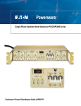
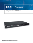
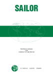
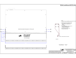
Remote Control Panels RCP100 & RCP200 Series
Enclosure Power Distribution Units (ePDU™)
RCP100 Series
RCP100-BLK-LT
EMERGENCY POWER OFF (EPO)
• RCP100-GRY: Locking (N/O) EPO button for PDUs with the
standard 3 pin remote I/O port. Turn to reset
• RCP100-GRY-LT: Locking (N/C) EPO button for PDUs with the
latching (LT) option. Turn to reset.
• Per European requirements, there is a yellow square behind the
EPO button
RCP100-GRY
RACK MOUNTED
• 19” x 1.73” x 2.0”, flush mounted, 18 GA. Steel
• Painted FED-STD 595 #26559 light texture Gray
• Optional: Painted FED-STD 595 #26038 Black
• Remote cable is 15’ long
• Approximate shipping weight is 5 lbs.
ON/OFF SWITCH
• RCP100-GRY: 2 position “ON/OFF” switch
• RCP100-GRY-LT: 3 position spring return dial switch for
“OFF” (turns unit off and holds off), “ON” (puts unit in a standby mode),
“START” is a momentary action and powers up the unit
RCP200 Series
EMERGENCY POWER OFF (EPO)
• RCP200-GRY: Locking (N/O) EPO button for PDUs with the
standard 3 pin remote I/O port. Turn to reset
• RCP200-GRY-LT: Locking (N/C) EPO button for PDUs with the
latching (LT) option. Turn to reset.
• Per European requirements, there is a yellow square behind the
EPO button
RCP200-BLK-LT
ON/OFF SWITCH
• RCP200-GRY: 2 position “ON/OFF” switch
• RCP200-GRY-LT: 3 position spring return dial switch for “OFF”
(turns unit off and holds off), “ON” (puts unit in a standby mode),
“START” is a momentary action and powers up the unit
RCP200-GRY-LT
RACK MOUNTED
• 19” x 3.46” x 2.0”, flush mounted, 18 GA. Steel
• Remote cable is 15’ long
• Painted FED-STD 595 #26559 light texture Gray
• Optional: Painted FED-STD 595 #26038 Black
• Approximate shipping weight is 7 lbs.
(2) NEMA UTILITY OUTLETS
• Utility duplex (NEMA 5-15R) on front panel
POWER INPUT
• 14/3 AWG power cable is attached to the rear of the duplex and
is 6’ long terminated with a NEMA 5-15P
Latching (LT) control panels must be ordered with power distribution units
that are latching, identified by LT at the end of the part number.
MODEL
REMOTE TYPE
HEIGHT
COLOR
RECEPTACLE
SWITCH/EPO
RCP100-GRY
Standard
1U (1.75”)
Gray
None
2 position/Normally Open
RCP100-BLK
Standard
1U (1.75”)
Black
None
2 position/Normally Open
RCP100-GRY-LT
Latching
1U (1.75”)
Gray
None
3 position/Normally Closed
RCP100-BLK-LT
Latching
1U (1.75”)
Black
None
3 position/Normally Closed
RCP200-GRY
Standard
2U (3.5”)
Gray
(2) NEMA 5-15A
2 position/Normally Open
RCP200-BLK
Standard
2U (3.5”)
Black
(2) NEMA 5-15A
2 position/Normally Open
RCP200-GRY-LT
Latching
2U (3.5”)
Gray
(2) NEMA 5-15A
3 position/Normally Closed
RCP200-BLK-LT
Latching
2U (3.5”)
Black
(2) NEMA 5-15A
3 position/Normally Closed
www.pulizzi.com • [email protected] • 800-870-2248 • Fax: 605-334-4999
© 2008 Eaton Corporation. All Rights Reserved. All specifications are subject to change without notice.
2
Standard Remote Control Interface
REMOTE START REQUIRES (2) CONDITIONS:
1. The “on/off/remote” switch must be in the “remote” position.
2. A maintained closure between pins 1 & 3 will turn the unit on.
REMOTE POWER OFF REQUIRES (1) CONDITION:
1. Opening the maintained connection between pins 1 & 3 will
turn off the switched outlets.
REMOTE EPO REQUIRES (1) CONDITION:
1. A maintained contact between pins 2 & 3 will turn off
the switched outlets regardless of the position of the
“on/off/remote” switch.
SEQUENCED REMOTE:
Connect pins 1, 2 & 3 of the sequence port to pins 1, 2 & 3 on any remote
port of the slave unit. (Do not connect to another “sequence” port!)
The sequence port of the master unit activates 4 seconds after the final set
of outlets turn on. Additional units may be daisy chained in this fashion.
CAUTION!
THIS TYPE OF REMOTE IS NOT TO BE SUBSTITUTED
FOR A SAFETY INTERLOCK!
EPO is normally open, so removing the EPO connection
will not shut down the power to the unit.
Latching Remote “LT” Control Interface
REMOTE START REQUIRES (2) CONDITIONS:
1. A maintained contact between pins 2 & 3.
2. A momentary contact between pins 1 & 3.
REMOTE POWER OFF OR EPO REQUIRES (1) CONDITION:
1. Opening the maintained connection between pins 2 & 3.
Additional EPO or stop buttons can be connected in series
between pins 2 & 3.
This will turn off the switched outlets regardless of the
remote switch position.
SEQUENCE REMOTE:
Connect pins 1 & 2 of the “sequence” port to any remote port on
another “-LT” unit. The sequence port activates 4 seconds after the
final set of outlets turn on.
(Do not connect to another “sequence” port!)
NOTE: “LT” units are designed for remote operation only.
Even when the “REMOTE/OFF/LOCAL” switch is set to “LOCAL”,
the unit still requires a power request from the remote ports to
turn the unit on.
REMOTE OPERATION: Most Pulizzi® units have more than one remote connector. Unless labeled as “SEQUENCE” they are wired in parallel. Connection
to only one remote connector is required. It is recommended that a Pulizzi® control panel be ordered for use with your PDU. Connectors are provided for
those who wish to wire their own switches or control panels. We recommend using 14 AWG wire and not exceeding 50 feet for any remote cable. Mating
control panels can be seen on our web site at www.pulizzi.com.
If additional remote connectors are needed: The female AMP connectors used in our Power Controllers are: three pin - Part Number
1-480304-0 and four pin Part Number 1-480425-0, and are used with AMP Socket Terminals, Part Number 60619-1. The mating male AMP connector is:
three pin - Part Number 1-480305-0, and four pin - Part Number 1-480426-0 and are used with AMP male contacts Part Number 60620-1.
Environmental
Operating Temperature is 0 to 50 C
Storage Temperature is -40 to 70 C
Altitude Maximum 10,000 ft.
Relative Humidity is 95% Max Non-Condensing
www.pulizzi.com • [email protected] • 800-870-2248 • Fax: 605-334-4999
© 2008 Eaton Corporation. All Rights Reserved. All specifications are subject to change without notice.
3
RCP100-BLK-LT
RCP100-GRY
Drawings are not shown to scale Dimensions are in inches
RCP200-GRY-LT
RCP200-GRY
4
www.pulizzi.com • [email protected] • 800-870-2248 • Fax: 605-334-4999
© 2008 Eaton Corporation. All Rights Reserved. All specifications are subject to change without notice.