1
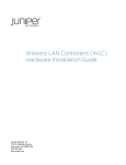
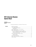
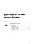
WX 15, WX 20 and WXC 250 Quick Start Welcome to the Juniper WX 15, WX 20, and WXC 250 application acceleration platforms quick start. These one rack-unit (1U) network infrastructure devices are deployed on the LAN side of the edge router. This quick start card describes how to install the WX/WXC in the data path between a switch and a router. To install the WX/WXC “off-path” (connected only to the switch or router), refer to the WX/WXC Operator’s Guide. If you have any problems with the licensing process, open a support case using the Case Management link at http://www.juniper.net/support/. To call from the United States, Canada, or Mexico, dial 1-888-314-JTAC. To call from other locations, check the list of local support centers at http://www.juniper.net/support/support_contacts.html or dial 1-408-745-9500. Before You Begin Installation Inspect the package contents. Refer to the package contents document enclosed with the product. Perform the following steps to install your WX 15, WX 20 or WXC 250 platform: Ensure sufficient power is available. Supply circuits should be protected by a 15 A or 20 A circuit breaker. 1. Set up the chassis. Ensure a minimum of six inches clearance in the front and back of the chassis. For a WX 15, provide three inches of clearance on both sides of the chassis to allow cooling air to be drawn through the side panels. Verify that all firewalls between WX devices allow traffic on: TCP/UDP ports 3577 and 3578 IP payload compression protocol (protocol number 108). Identify a 10/100 Ethernet LAN port that transmits data to your WAN router. This port is typically from an aggregation switch, or from another LAN device connected directly to the router. Obtain a license key. The license key determines the throughput levels for the device, and properly registers the product. To obtain a permanent license key, go to: For rack mount installation, install the supplied brackets, front panel forward, to the sides of the device (Figure 1). For desktop installation, install the rubber stands in the recessed areas on the bottom of the chassis (pre-installed on the WX 15 platform). NOTE: Do not connect the power cable until Step 4. Figure 1. Mounting a WX/WXC device in a rack POWER STATUS OP BYPASS DISABLE WX 15 https://www.juniper.net/generate_license If you operate the platform at its base speed, only the serial number is needed to generate a permanent license. If you purchased license upgrades, you will need the Authorization Code Certificate that was emailed to you in electronic PDF format. TTW_046 WX 15, WX 20, and WXC 250 Quick Start 3. Verify connectivity across the WX/WXC device. 2. Connect the network cables. Locate the cable that connects from the switch (or other aggregating device) to the router. Disconnect this cable from the router port and connect it to the LOCAL port on the WX/WXC device. Connect a straight-through cable (not provided) from the router port to the REMOTE port on the WX/WXC device. See Figure 2. Figure 2. One method of testing connectivity between devices is to Ping a host on the remote side of the device from a host on the local side of the device. NOTE: If you are not able to verify connectivity on both sides of the device, do not proceed to the next step. Ensure that you are using the correct cables (crossover vs. straight-through), and verify that there is network connectivity before applying power. 4. Connect the power. Connecting network cables to a WX/WXC device Connect the power cable to the back of the chassis, and then connect the other end of the power cable to your local power source (Figure 3). Router (remote device) NOTE: The power usage is 50 Watts Max or 170 BTU/hr for the WX 15, and 150 Watts Max or 510 BTU/hr for the WX 20 and WXC 250. WX 15 STOP: You may be able to use the autodeployment feature of the Model No. SR-15 PERIBIT NETWORKS |||||||||||||||||||||||||||||||||||||||||||||||||| S/N 0123456789 100/10 LINK WX CMS software to configure the device automatically. Refer to the CMS administrator’s guide for more information or continue with Step 5. LINK 100/10 BYPASS DISABLE 100/240V 50-60 ~ 1/.5A LOCAL REMOTE CONSOLE Figure 3. Connecting power to a WX/WXC device Model No. SR-15 PERIBIT NETWORKS |||||||||||||||||||||||||||||||||||||||||||||||||| S/N 0123456789 Switch (local device) 100/10 LINK LINK 100/10 100/10 LINK LINK 100/10 BYPASS DISABLE 100/240V 50-60 ~ 1/.5A LOCAL REMOTE CONSOLE TTW_048 LOCAL REMOTE TTW_047 WX 15, WX 20, and WXC 250 Quick Start 5. Configure network settings. Connect an ANSI-compatible terminal to the serial port, and use a terminal emulation program (e.g., HyperTerminal) to log in to the CLI (Figure 4). Figure 4. Finally, type the default gateway for this device and then press Enter. Type save-config and type y to confirm. You can safely bypass the other configuration questions at this time. NOTE: By default, the 10/100 interfaces are set to auto-negotiate Connecting a WX/WXC to a serial port the speed and duplex mode. However, you may want to set the interface speed and duplex mode manually. The LOCAL port settings should match the interface settings of the switch, and the REMOTE port settings should match the interface settings of the router. 6. Check the LEDs next to the 10/100 Ethernet ports. Model No. SR-15 PERIBIT NETWORKS |||||||||||||||||||||||||||||||||||||||||||||||||| S/N 0123456789 100/10 LINK LOCAL REMOTE CONSOLE If the LINK LEDs illuminate, the device is properly connected (Figure 5). If they do not illuminate, toggle the MDI/MDI-X buttons (WX 20 and WXC 250 platforms only). The 100/10 LEDs indicate 100 Mbps connectivity. On the WX 15 platform, press Bypass Disable to block traffic during a power failure (used in high-availability environments). LINK 100/10 BYPASS DISABLE 100/240V 50-60 ~ 1/.5A TTW_049 After checking the LEDs, verify connectivity across the device again (as described in Step 3). Figure 5. Use the following serial port settings: Baud Rate: 9600 Parity: NONE Flow Control: NONE Data Bits: 8 Stop Bits: 1 Smooth-Scroll: DISABLED Start the terminal emulation program, and choose to connect via the serial port. At the User name and Password prompts, type admin for the user name and juniper for the password. Type an IP address and then press Enter. Next, type the subnet mask for the network and then press Enter. Verifying network connectivity 100/10 LINK LINK 100/10 LOCAL REMOTE TTW_050 WX 15, WX 20, and WXC 250 Quick Start Quick Setup After powering on the device and assigning IP parameters, the next step is to log in to the Web console and run the Quick Setup program. The first time you log in to the Web console, the Quick Setup program starts automatically and guides you through initial configuration options for the device. For more information about Demo Mode, refer to the Operator’s Guide. If you select Active Mode, click Next to continue. If you select Demo Mode, click Next, and then click Finish. 3. Set the time. Enter the current date and time or, if your network uses an NTP server for time settings, select Use NTP Server and enter the IP address of the NTP server in the Primary field. A secondary NTP server is optional. To log in to the Web console and run Quick Setup, follow these steps: Select the local time zone for the device. 1. From a workstation within your network, start your Web browser and enter the following URL: Click Next to continue. You can log in to the Web console from any workstation within your network. The Web console supports Microsoft Internet Explorer version 6.0. Data is securely transmitted through HTTPS. 4. Designate a registration server. https://(ip address of the WX device) One device must be designated as the Registration Server. If the Security Alert dialog box appears, click Yes to proceed. In the Login page, type admin for the user name and juniper for the password. Click Login. 2. Select an operating mode. If this device is not the registration server, enter the IP address and password of the current (or future) registration server in the appropriate fields. This device will not process data until the registration server is configured. To designate this device as the registration server, select Make this device the Registration Server, and enter the registration server password in both fields. A device can run in Active mode or Demo Mode. Active Mode—Device is actively reducing data, accelerating TCP applications, and managing bandwidth. Demo Mode—Device is operating passively. It can calculate potential data compression statistics for all traffic, individual applications, and specific remote subnets; however, the actual traffic is not affected. NOTE: To use Demo Mode, the device’s Local interface must be connected to a mirrored port on the switch, and the Remote interface must be disconnected. If you have installed the device inline, do not select Demo Mode as data will be dropped. The registration server password authenticates the devices in a community, and should be different from the administrator password. Click Next to continue. 5. Enter a license key. By default, each device has a 30-day evaluation license. When the evaluation license expires, data will pass through the device without any processing. If you have a permanent license key, select Enter license key now, and enter the key in the License key field. Click Next, and then click Finish. Where to Go Next Initial configuration is complete. Please refer to the operator’s guide to configure policy settings for the device. The latest WX/WXC Operator’s Guide and WX CMS Administrator’s Guide can be found at the following website: http://www.juniper.net/techpubs/hardware/wx The latest WXOS and CMS Release Notes can be found at the Juniper CSC (Customer Support Center) Website (requires customer login): https://www.juniper.net/customers/csc/software/appaccel/wxseries For technical support, open a support case using the Case Management link at http://www.juniper.net/support/. To call from the United States, Canada, or Mexico, dial 1-888-314-JTAC. To call from other locations, check the list of local support centers at http://www.juniper.net/support/support_contacts.html or dial 1-408-745-9500. Juniper Networks, the Juniper Networks logo, NetScreen, NetScreen Technologies, the NetScreen logo, NetScreen-Global Pro, ScreenOS, and GigaScreen are registered trademarks of Juniper Networks, Inc. in the United States and other countries. The following are trademarks of Juniper Networks, Inc.: ERX, ESP, E-series, Instant Virtual Extranet, Internet Processor, J2300, J4300, J6300, J-Protect, J-series, J-Web, JUNOS, JUNOScope, JUNOScript, JUNOSe, M5, M7i, M10, M10i, M20, M40, M40e, M160, M320, M-series, MMD, NetScreen-5GT, NetScreen-5XP, NetScreen-5XT, NetScreen-25, NetScreen-50, NetScreen-204, NetScreen-208, NetScreen-500, NetScreen-5200, NetScreen-5400, NetScreen-IDP 10, NetScreen-IDP 100, NetScreen-IDP 500, NetScreen-Remote Security Client, NetScreen-Remote VPN Client, NetScreen-SA 1000 Series, NetScreen-SA 3000 Series, NetScreen-SA 5000 Series, NetScreen-SA Central Manager, NetScreen Secure Access, NetScreen-SM 3000, NetScreen-Security Manager, NMC-RX, SDX, Stateful Signature, T320, T640, T-series, and TX Matrix. All other trademarks, service marks, registered trademarks, or registered service marks are the property of their respective owners. All specifications are subject to change without notice. Copyright 2007, Juniper Networks, Inc. All rights reserved. Printed in USA. Part Number: 100801-03, Revision 1.0, 10 January 2008.