1
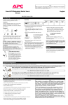
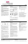
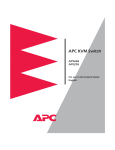
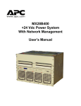
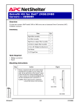
MasterSwitch Power Distribution Unit AP9211 AP9212 AP9217 AP9218 Installation and Quick Start Manual ® This document is available in English on the enclosed CD. ❖❖❖ Dieses Dokument ist in Deutsch auf der beiliegenden CD-ROM verfügbar. ❖❖❖ Este documento está disponible en español en el CD-ROM adjunto. ❖❖❖ Ce document est disponible en français sur le CD-ROM ci-inclus. Contents Preliminary Information . . . . . . . . . . . . . . . . . . . . . 1 Features of the MasterSwitch PDU 1 Inventory 2 Please recycle 2 Installing MasterSwitch . . . . . . . . . . . . . . . . . . . . . 3 Overview 3 Mounting in a NetShelter enclosure 3 Quick Configuration . . . . . . . . . . . . . . . . . . . . . . . 5 Required configuration 5 Configuring TCP/IP settings 5 Accessing the MasterSwitch PDU 8 Documentation on the CD . . . . . . . . . . . . . . . . . . . 9 Radio Frequency Interference . . . . . . . . . . . . . . . 10 APC Worldwide Customer Support Preliminary Information Features of the MasterSwitch PDU American Power Conversion’s MasterSwitch™ Power Distribution Unit (PDU) is a stand-alone, network-manageable device that allows programmable control of eight power outlets. MasterSwitch models AP9211 and AP9217 have NEMA 5-15 outlets. MasterSwitch models AP9212 and AP9218 have IEC-320 C13 outlets. You can remotely control a MasterSwitch PDU through its Web, SNMP, or Control Console network interfaces. Both MasterSwitch models have these additional features: • For each outlet, independent control of the following: – Power On Delay – Power Off Delay – Reboot Duration • Power-up sequencing • 16 independent Outlet User accounts • Basic and MD5 authentication for password security. • Three levels of user access accounts: – Administrator – Device Manager – Outlet User • An auto-configuration utility that you can use to create a configuration file, which you can then download to other MasterSwitch PDUs, individually or as a group. For more information, see the Management Card Addendum (addendum.pdf on the MasterSwitch CD-ROM). Continued on next page 1 Preliminary Information continued Features of the MasterSwitch PDU, continued • An event log that you can display through the Control Console or Web interface to import into a spreadsheet application. • Compact design that requires only one U of rack space. • The ability to upgrade MasterSwitch firmware without affecting outlet state. Note: The MasterSwitch PDU does not provide power protection. Therefore, APC does not recommend plugging a unit directly into any unprotected power source, such as a wall outlet. Inventory The MasterSwitch PDU is shipped with the following items: • A pre-installed Web/SNMP Management SmartSlot Card • A null-modem cable • A CD-ROM containing product documentation and the Management Card Wizard • Rack-mount brackets and self-tapping Phillips screws • This Installation and Quick Start Manual • A warranty registration card Please recycle 2 The shipping materials are recyclable. Save them for later reuse, or dispose of them properly. Installing MasterSwitch Overview Mounting in a NetShelter enclosure You can place the MasterSwitch PDU on a desktop or mount it in an enclosure. The procedure below instructs how to mount the unit in an APC NetShelter® Premium enclosure. You can also mount the unit into other EIA-310-D standard 19-inch racks. :. ! Remove the rubber feet from the bottom of the unit. " Attach the mounting brackets to the unit, using the two selftapping Phillips screws provided for each bracket. Continued on next page 3 Installing MasterSwitch continued Mounting in a NetShelter enclosure, continued # Choose a location that will occupy one U of space in the enclosure. (A notched hole on the vertical rail denotes the middle of a U-space.) $ Install a caged nut (provided with the enclosure) above and below a notched mounting hole on each vertical mounting rail. % Align the mounting holes of the brackets with the installed caged nuts. Insert and tighten the screws. 4 Quick Configuration Required configuration You must configure the following network settings for the MasterSwitch PDU before it can operate on a network: • IP address of the MasterSwitch PDU • Subnet Mask • IP address of the default gateway After you configure MasterSwitch network settings, no further configuration is required. The remaining MasterSwitch properties are pre-configured at the factory. However, you may want to customize these properties for your application. See “Managing the MasterSwitch PDU” in the User’s Guide on the enclosed CD for more information. Configuring TCP/IP settings Choose the configuration method appropriate for your environment: • If you are using Windows 95, Windows 98, or Windows NT, see “Through the Management Card Wizard” on page 5. • If you are not using a Windows-based operating system or if you require direct serial configuration, see “Serially through the Control Console” on page 6. • If you are a network administrator using Address Resolution Protocol (ARP), see “Over the Network by ARP” on page 7 • If you are a network administrator using BOOTP, see “Over the Network by BOOTP” on page 7. Through the Management Card Wizard. On Windows 95, Windows 98, or version 4.0 of Windows NT, use the Management Card Wizard to configure all attributes quickly, including TCP/IP settings, for the pre-installed Management Card. Use the CD-ROM supplied with the MasterSwitch PDU and follow the on-screen instructions. The pre-installed Management card provides the network interface for the MasterSwitch PDU. Continued on next page 5 Quick Configuration continued Configuring TCP/IP settings, continued Serially through the Control Console. If you are not using a Windows platform, or you require direct serial configuration, use the Serial Console port to configure the TCP/IP settings for the Management Card, as follows: 1. Connect the supplied null-modem cable (APC part number 940-0103) to an available serial port on your computer and to the serial port on the front panel of the MasterSwitch unit. 2. Disable PowerChute Plus, UNIX Respond, or other service that may be using the serial port on the computer. 3. Run a terminal emulator such as Windows HyperTerminal. Configure the appropriate serial port with the following settings: 2400 bps, no parity, 8 data bits, 1 stop bit, and no flow control. Note: Some terminal emulators, such as HyperTerminal, require that you disconnect and reconnect in order for the new serial settings to take effect. 4. From your computer, press ENTER until the user name prompt appears. 5. Enter the default user name and password: apc in lowercase. 6. On the Main menu, choose Network. 7. From the Network menu, choose TCP/IP. 8. Within the TCP/IP menu do the following: a. Disable BOOTP, and accept changes. b. Set a valid IP address, Subnet Mask and default gateway for your network, and accept changes. c. Press ESC until the Main menu appears, then select Logout. Note: The new settings take effect when you log out. Continued on next page 6 Quick Configuration continued Configuring TCP/IP settings, continued Over the Network by ARP. To configure the TCP/IP settings of the MasterSwitch PDU using Address Resolution Protocol (ARP), perform the following steps: 1. Set up the unit and connect it to the network. 2. From a command prompt on a computer connected to the local subnet, type arp -s ip_addr_card mac_card. For example: arp -s 159.215.240.22 00-c0-b7-78-ad-90 Note: To obtain the MAC address, see the Quality Assurance slip, look on the bottom of the unit, or select the TCP/IP menu from the Control Console. 3. Type telnet ip_addr. See the example below: telnet 159.215.240.22 The default user name and password are both apc. Configure the correct Subnet Mask and default gateway in the TCP/IP section of the Network menu. Over the Network by BOOTP. BOOTP is enabled by default. Use a BOOTP server to configure MasterSwitch TCP/IP settings and to perform the following steps: 1. Enter the MasterSwitch MAC address, IP address, subnet mask, default gateway and optional boot-up file name. Note: To obtain the MAC address, see the Quality Assurance slip, look on the bottom of the unit, or select the TCP/IP menu from the Control Console. Continued on next page 7 Quick Configuration continued Configuring TCP/IP settings, continued 2. The BOOTP server provides network settings to the MasterSwitch PDU. If a boot-up file name was specified, the MasterSwitch PDU attempts to transfer that file from a TFTP or FTP server on the same computer as the BOOTP server. The MasterSwitch assumes all settings specified in the boot-up file. Note: You must use the Management Card Configuration Wizard to create the boot-up file. Alternatively, you can configure the MasterSwitch PDU remotely using the Telnet, Web, or SNMP interface. Accessing the MasterSwitch PDU You can access the MasterSwitch PDU through a Web browser, Telnet, or SNMP interface, as described below. Through a Web browser. Perform the following steps: 1. From your Web browser, enter the System IP address of the MasterSwitch PDU, or enter its DNS name (if a DNS name is configured). 2. Log on to the MasterSwitch PDU, using the default User Name and Password apc (lowercase). Through Telnet. Perform the following steps: 1. From your Telnet session, enter the System IP address of the MasterSwitch PDU. 2. Log on to the MasterSwitch PDU, using the default User Name and Password apc (lowercase). Through an SNMP interface. Accessing the MasterSwitch PDU using SNMP requires a Network Management Station, running management software such as HP OpenView. The default read-only community name is public. The default read/write community name is private. Continued on next page 8 Documentation on the CD Additional documentation This Installation and Quick Start Manual and the online User’s Guide are available in English and additional languages on the supplied CD-ROM. The online User’s Guide contains information on the following: • • • • • • • • • • LEDs Customizing setup Management interfaces User accounts Outlet control actions Security Customer support Product specifications and approvals The APC warranty The APC life-support policy 9 Radio Frequency Interference Changes or modifications to this unit not expressly approved by the party responsible for compliance could void the user’s authority to operate this equipment. This equipment has been tested and found to comply with the limits for a Class A digital device, pursuant to part 15 of the FCC Rules. These limits are designed to provide reasonable protection against harmful interference when the equipment is operated in a commercial environment. This equipment generates, uses, and can radiate radio frequency energy and, if not installed and used in accordance with this manual, may cause harmful interference to radio communications. Operation of this equipment in a residential area is likely to cause harmful interference. The user will bear sole responsibility for correcting such interference. This Class A digital apparatus complies with Canadian ICES003. Cet appareil numérique de la classe A est conforme à la norme NMB-003 du Canada. 10 APC Worldwide Customer Support Customer support for this or any other APC product is available at no charge in any of the following ways: • Visit the APC Web site to find answers to frequently asked questions (FAQs), to access documents in the APC Knowledge Base, and to submit customer support requests. – http://www.apcc.com (Corporate Headquarters) Connect by links to APC Web pages for specific countries and regions, each of which provides customer support information. – http://www.apcc.com/support/ Submit customer support requests. • Contact an APC Customer Support center by telephone or e-mail. – Regional centers: . – • APC Headquarters (U.S. and Canada) (1) (800) 800-4272 (toll free) Latin America (1) (401) 789-5735 (United States) [email protected] Europe, Middle East, Africa (353) (91) 702020 (Ireland) [email protected] Japan (03) 5434-2021 [email protected] Local, country-specific centers: go to http://www.apcc.com/support/ contact for contact information. Contact the APC representative or other distributor from whom you purchased your APC product for information on how to obtain local customer support. Entire contents copyright © 2001 American Power Conversion. All rights reserved. Reproduction in whole or in part without permission is prohibited. APC, the APC logo, MasterSwitch, and NetShelter are trademarks or registered trademarks of American Power Conversion Corporation. All other trademarks, product names, and corporate names are the property of their respective owners and are used for informational purposes only. 996-6019C 07/2001