1
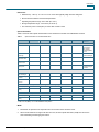
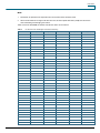
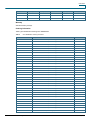
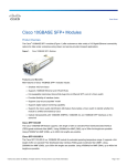
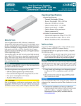
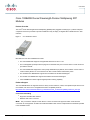
Data Sheet
Cisco 10GBASE Dense Wavelength-Division Multiplexing XFP
Modules
Product Overview
®
The Cisco Dense Wavelength-Division Multiplexing (DWDM) XFP pluggable module (Figure 1) allows enterprise
companies and service providers to provide scalable and easy-to-deploy 10 Gigabit LAN or WAN services in their
networks.
Figure 1.
Cisco DWDM XFP Module
Main features of the Cisco DWDM XFP include:
●
The Cisco DWDM XFP supports 10-Gigabit data rates from 9.9G to 11.1G.
●
The hot-swappable input/output device plugs into an Ethernet XFP port of a Cisco switch or router to link the
port with the network.
●
The Cisco DWDM XFP supports the Cisco quality identification (ID) feature, which enables a Cisco switch or
router to identify whether or not the module is an XFP module certified and tested by Cisco.
●
The standard Cisco DWDM XFP supports 32 nontunable ITU 100-GHz wavelengths.
●
The tunable Cisco DWDM XFP supports 80 tunable ITU 50-GHz wavelengths.
●
Cisco DWDM XFP modules supports digital optical monitoring capability.
Platform Support
The Cisco DWDM XFPs are supported across a variety of Cisco switches, routers, and optical transport devices. For
more details, refer to the Cisco 10-Gigabit transceivers compatibility matrix at:
http://www.cisco.com/en/US/docs/interfaces_modules/transceiver_modules/compatibility/matrix/OL_6974.pdf
Connectors and Cabling
●
Equipment: standard XFP interface
●
Network: dual LC/PC connector
Note:
Only connections with patch cords with PC or UPC connectors are supported. Patch cords with APC
connectors are not supported. All cables and cable assemblies used must be compliant with the standards specified
in the standards section.
© 2010 Cisco and/or its affiliates. All rights reserved. This document is Cisco Public Information.
Page 1 of 6
Data Sheet
Dimensions
●
Dimensions (L x W x H): 71 x 18.5 x 8.5 mm. Cisco XFPs typically weigh less than 300 grams.
●
Environmental Conditions and Power Requirements.
●
Operating temperature range: 32 to 158°F (0 to 70°C ).
●
Storage temperature range: -40 to 185°F (-40 to 85° C).
●
The maximum power consumption per Cisco XFP module is 3.5W.
Optical Parameters
Table 1 shows the main optical characteristics for the standard non-tunable Cisco DWDM XFP modules.
Table 1.
Optical Parameters for standard DWDM XFP
Parameter
Symbol
Minimum
Typical
Maximum
Units
Notes and
Conditions
0.2
nm
Full width, -20 dB
from maximum,
with resolution
bandwidth (RBW) =
0.01 nm
x + 100
pm
Refer to Table 2 for
center wavelengths
Transmitter
Spectral width
Transmitter center
wavelength
x - 100
x
Side-mode
suppression ratio
SMSR
30
dB
Transmitter
extinction ratio
OMI
9
dB
Transmitter optical
output power
Pout
-1.0
3.0
dBm
1530
1565
nm
4.0
dBm
1600
ps/nm
Average power
coupled into singlemode fiber
Receiver
Receiver optical
input wavelength
Receiver damage
threshold
Dispersion
tolerance
-500
Power-Limited Performance (measured at optical signal-to-noise ratio [OSNR] of 30 dB at 0.1-nm RBW)
Optical input power
Pin
-23.0
Dispersion power
penalty
*
-7.0
dBm
See footnote
3
dB
See footnote
-7.0
dB
See footnote
3
dB
See footnote
*
Noise-Limited Performance (measured at OSNR of 24 dB at 0.1-nm RBW)
Optical input power
Pin
-18.0
Dispersion OSNR
penalty
*
*
*
At bit error rate (BER) = 1E-12 with IEEE802.3 test pattern.
Note:
1.
2.
Parameters are specified over temperature and at end of life unless otherwise noted.
When shorter distances of single-mode fiber are used, an inline optical attenuator (10-dB) must be used to
avoid overloading and damaging the receiver.
© 2010 Cisco and/or its affiliates. All rights reserved. This document is Cisco Public Information.
Page 2 of 6
Data Sheet
Table 2 shows the main optical characteristics for the tunable Cisco DWDM XFP modules.
Table 2.
Parameter
Optical Parameters for tunable DWDM XFP
Symbol
Minimum
Typical
Maximum
Units
Notes and Conditions
0.2
nm
Full width, -20 dB from maximum, with resolution
bandwidth (RBW) = 0.01 nm
x + 25
Pm
Refer to Table 3 for center wavelengths
Transmitter
Spectral width
Transmitter
center
wavelength
x - 25
X
Side-mode
suppression
ratio
SMSR
30
dB
Transmitter
extinction
ratio
OMI
9
dB
Transmitter
optical output
power
Pout
0.0
3.0
dBm
1530
1565
nm
4.0
dBm
1600
ps/nm
Average power coupled into single-mode fiber
Receiver
Receiver
optical input
wavelength
Receiver
damage
threshold
Dispersion
tolerance
-500
Receiver Power Performance
Units
Range
Notes and Conditions
Long Wavelength Performances C Band NO-FEC Applications Power-Limited
Input power range
dBm
-7 to -24
At BER=10e-12 applicable at 9.9G and 10.3G, 30dB
OSNR (0.1nm RBW)
Input power range
dBm
-7 to -22
At BER=10e-12 (-500 to +1600 ps/nm) applicable at
9.9G and 10.3G, 30dB OSNR (0.1nm RBW)
Long Wavelength Performances C Band NO-FEC Applications Noise-Limited
Input power range
dBm
-7 to -22
At BER=10e-12 applicable at 9.9G and 10.3G, 26dB
OSNR (0.1nm RBW)
Input power range
dBm
-7 to -20
At BER=10e-12 (-500 to +1600 ps/nm) applicable at
9.9G and 10.3G, 26dB OSNR (0.1nm RBW)
Long Wavelength Performances C Band FEC Applications Noise-Limited
Input power range
dBm
-7 to -18
At BER PREFEC <10e-5 applicable at 10.7G and
11.1G, 15.5dB OSNR (0.1nm RBW)
Input power range
dBm
-7 to -18
At BER PREFEC <10e-5 (-500 to +1000 ps/nm)
applicable at 10.7G and 11.1G, 17dB OSNR (0.1nm
RBW)
Long Wavelength Performances C Band E-FEC Applications Power-Limited
*
Input power range
dBm
-7 to -27
At BER PREFEC <7 10e-4 applicable at 10.7G and
11.1G, 26dB OSNR (0.1nm RBW)
Input power range
dBm
-7 to -26
At BER PREFEC <7 10e-4 (-500 to +1300 ps/nm)
applicable at 10.7G and 11.1G, 26dB OSNR (0.1nm
RBW)
*
Long Wavelength Performances C Band E-FEC Applications Noise-Limited
*
Input power range
dBm
-7 to -20
At BER PREFEC <7 10e-4 applicable at 10.7G and
11.1G, 12dB OSNR (0.1nm RBW)
Input power range
dBm
-7 to -20
At BER PREFEC <7 10e-4 (-500 to +1300 ps/nm)
applicable at 10.7G and 11.1G, 14dB OSNR (0.1nm
RBW)
© 2010 Cisco and/or its affiliates. All rights reserved. This document is Cisco Public Information.
*
Page 3 of 6
Data Sheet
Note:
1.
Parameters are specified over temperature and at end of life unless otherwise noted.
2.
When shorter distances of single-mode fiber are used, an inline optical attenuator (10-dB) must be used to
avoid overloading and damaging the receiver.
Table 3 shows the 80 DWDM ITU-50GHz channels the device can be tuned to.
Table 3.
ITU 50-GHz center wavelengths and channel numbering
Channel Id
Frequency (THz)
Wavelength (nm)
Channel Id
Frequency (THz)
Wavelength (nm)
80
195.9
1530.33
79
195.85
1530.72
78
195.8
1531.12
77
195.75
1531.51
76
195.7
1531.90
75
195.65
1532.29
74
195.6
1532.68
73
195.55
1533.07
72
195.5
1533.47
71
195.45
1533.86
70
195.4
1534.25
69
195.35
1534.64
68
195.3
1535.04
67
195.25
1535.43
66
195.2
1535.82
65
195.15
1536.22
64
195.1
1536.61
63
195.05
1537.00
62
195.0
1537.40
61
194.95
1537.79
60
194.9
1538.19
59
194.85
1538.58
58
194.8
1538.98
57
194.75
1539.37
56
194.7
1539.77
55
194.65
1540.16
54
194.6
1540.56
53
194.55
1540.95
52
194.5
1541.35
51
194.45
1541.75
50
194.4
1542.14
49
194.35
1542.54
48
194.3
1542.94
47
194.25
1543.33
46
194.2
1543.73
45
194.15
1544.13
44
194.1
1544.53
43
194.05
1544.92
42
194.0
1545.32
41
193.95
1545.72
40
193.9
1546.12
39
193.85
1546.52
38
193.8
1546.92
37
193.75
1547.32
36
193.7
1547.72
35
193.65
1548.11
34
193.6
1548.51
33
193.55
1548.91
32
193.5
1549.32
31
193.45
1549.72
30
193.4
1550.12
29
193.35
1550.52
28
193.3
1550.92
27
193.25
1551.32
26
193.2
1551.72
25
193.15
1552.12
24
193.1
1552.52
23
193.05
1552.93
22
193.0
1553.33
21
192.95
1553.73
20
192.9
1554.13
19
192.85
1554.54
18
192.8
1554.94
17
192.75
1555.34
16
192.7
1555.75
15
192.65
1556.15
14
192.6
1556.55
13
192.55
1556.96
12
192.5
1557.36
11
192.45
1557.77
10
192.4
1558.17
9
192.35
1558.58
8
192.3
1558.98
7
192.25
1559.39
© 2010 Cisco and/or its affiliates. All rights reserved. This document is Cisco Public Information.
Page 4 of 6
Data Sheet
Channel Id
Frequency (THz)
Wavelength (nm)
Channel Id
Frequency (THz)
Wavelength (nm)
6
192.2
1559.79
5
192.15
1560.20
4
192.1
1560.61
3
192.05
1561.01
2
192.0
1561.42
1
191.95
1561.83
Warranty
Standard warranty: 90 days.
Ordering Information
Table 4 gives details about ordering Cisco DWDM XFPs.
Table 4.
Cisco DWDM XFP Ordering Information
Product Number
Description
ITU Channel
DWDM-XFP-60.61=
10GBASE-DWDM 1560.61 nm XFP (100-GHz ITU grid)
21
DWDM-XFP-59.79=
10GBASE-DWDM 1559.79 nm XFP (100-GHz ITU grid)
22
DWDM-XFP-58.98=
10GBASE-DWDM 1558.98 nm XFP (100-GHz ITU grid)
23
DWDM-XFP-58.17=
10GBASE-DWDM 1558.17 nm XFP (100-GHz ITU grid)
24
DWDM-XFP-56.55=
10GBASE-DWDM 1556.55 nm XFP (100-GHz ITU grid)
26
DWDM-XFP-55.75=
10GBASE-DWDM 1555.75 nm XFP (100-GHz ITU grid)
27
DWDM-XFP-54.94=
10GBASE-DWDM 1554.94 nm XFP (100-GHz ITU grid)
28
DWDM-XFP-54.13=
10GBASE-DWDM 1554.13 nm XFP (100-GHz ITU grid)
29
DWDM-XFP-52.52=
10GBASE-DWDM 1552.52 nm XFP (100-GHz ITU grid)
31
DWDM-XFP-51.72=
10GBASE-DWDM 1551.72 nm XFP (100-GHz ITU grid)
32
DWDM-XFP-50.92=
10GBASE-DWDM 1550.92 nm XFP (100-GHz ITU grid)
33
DWDM-XFP-50.12=
10GBASE-DWDM 1550.12 nm XFP (100-GHz ITU grid)
34
DWDM-XFP-48.51=
10GBASE-DWDM 1548.51 nm XFP (100-GHz ITU grid)
36
DWDM-XFP-47.72=
10GBASE-DWDM 1547.72 nm XFP (100-GHz ITU grid)
37
DWDM-XFP-46.92=
10GBASE-DWDM 1546.92 nm XFP (100-GHz ITU grid)
38
DWDM-XFP-46.12=
10GBASE-DWDM 1546.12 nm XFP (100-GHz ITU grid)
39
DWDM-XFP-44.53=
10GBASE-DWDM 1544.53 nm XFP (100-GHz ITU grid)
41
DWDM-XFP-43.73=
10GBASE-DWDM 1543.73 nm XFP (100-GHz ITU grid)
42
DWDM-XFP-42.94=
10GBASE-DWDM 1542.94 nm XFP (100-GHz ITU grid)
43
DWDM-XFP-42.14=
10GBASE-DWDM 1542.14 nm XFP (100-GHz ITU grid)
44
DWDM-XFP-40.56=
10GBASE-DWDM 1540.56 nm XFP (100-GHz ITU grid)
46
DWDM-XFP-39.77=
10GBASE-DWDM 1539.77 nm XFP (100-GHz ITU grid)
47
DWDM-XFP-38.98=
10GBASE-DWDM 1538.98 nm XFP (100-GHz ITU grid)
48
DWDM-XFP-38.19=
10GBASE-DWDM 1538.19 nm XFP (100-GHz ITU grid)
49
DWDM-XFP-36.61=
10GBASE-DWDM 1536.61 nm XFP (100-GHz ITU grid)
51
DWDM-XFP-35.82=
10GBASE-DWDM 1535.82 nm XFP (100-GHz ITU grid)
52
DWDM-XFP-35.04=
10GBASE-DWDM 1535.04 nm XFP (100-GHz ITU grid)
53
DWDM-XFP-34.25=
10GBASE-DWDM 1534.25 nm XFP (100-GHz ITU grid)
54
DWDM-XFP-32.68=
10GBASE-DWDM 1532.68 nm XFP (100-GHz ITU grid)
56
DWDM-XFP-31.90=
10GBASE-DWDM 1531.90 nm XFP (100-GHz ITU grid)
57
DWDM-XFP-31.12=
10GBASE-DWDM 1531.12 nm XFP (100-GHz ITU grid)
58
DWDM-XFP-30.33=
10GBASE-DWDM 1530.33 nm XFP (100-GHz ITU grid)
59
DWDM-XFP-C
10GBASE-DWDM tunable XFP (50-GHz ITU grid)
See table 3
© 2010 Cisco and/or its affiliates. All rights reserved. This document is Cisco Public Information.
Page 5 of 6
Data Sheet
Regulatory and Standards Compliance
Standards
●
GR-20-CORE: Generic Requirements for Optical Fiber and Optical Fiber Cable
●
GR-326-CORE: Generic Requirements for Single-Mode Optical Connectors and Jumper Assemblies
●
GR-1435-CORE: Generic Requirements for Multifiber Optical Connectors
Safety
●
Laser Class I 21CFR1040
●
Network Equipment Building Standards (NEBS) Level 3
For More Information
For more information about Cisco 10GBASE DWDM XFP modules, contact your sales representative.
Printed in USA
© 2010 Cisco and/or its affiliates. All rights reserved. This document is Cisco Public Information.
C78-458530-01
12/10
Page 6 of 6