1
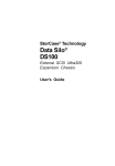
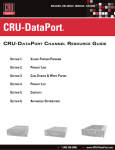
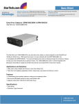
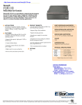
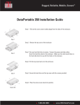
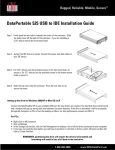
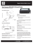
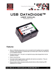
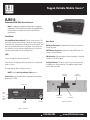
Rugged, Reliable, Mobile, Secure
TM
RJR110
Removable SATA 3Gb/s Drive Enclosure
Note: For applications requiring frequent drive swapping or
replacement, CRU-DataPort recommends the rugged DataPort
or Data Express removable enclosures for high insertion
environments.
Front Panel
Key Lock/Drive Power Switch: Performs three functions. The
key switch assures proper seating of the drive carrier within the
receiving frame, turns power to the drive carrier ON and OFF, and
prevents unauthorized removal or installation of the carrier. For
the computer to access data on the disk drive, the key must be
turned counterclockwise to the locked position.
LEDs
Rear Panel
DC Power Connector: Standard 4-pin DC Power Connector to
accept DC power.
SATA Power Connector: Alternative 15-pin SATA Power Connector to accept DC power.
I/O Connector: The input/output connector provides a standard
interface for all SATA signals.
Power - Steady glow indicates power ON.
Drive Activity - Steady glow indicates that drive is inserted and
ready for access.
Flashing indicates drive is being accessed.
Activity Indicator: This pin is used for host connection (cable
included) to the Activity Indicator. See additional detail under
Activity Indicator Cable.
NOTE: See the Activity Indicator Cable section.
Activity
Indicator Pin
DC Power
Connector
Carrier Fan: Front-mounted carrier fan provides enhanced heat
dissipation (4.7 CFM).
Carrier Fan
Power
LED
Drive
Activity
LED
SATA Power
Connector
Carrier
Handle
Key Lock
I/O
Connector
Figure 2: Rear Panel
Figure 1: Front Panel
1-800-260-9800
www.CRU-DataPort.com
Rugged, Reliable, Mobile, Secure
TM
Activity Indicator Cable
Insert SATA Drive
(not included)
This cable (provided) is used for host connection to the Activity Indicator Pin. Some SATA host controllers and system motherboards
provide support for the Activity Indicator feature (refer to the SATA
host controller or system motherboard manufacturer’s documentation for further information). Refer to Figure 2 for Activity Indicator
Pin location.
To Host Controller or
Bottom-Mount
Drive
System Motherboard
Figure 3: Activity
Indicator Cable
To Chassis Device Activity LED
Cable (optional)*
To RJR110 Activity
Indicator Pin
Figure 5: Installing a Drive into the Carrier
Product Warranty
CRU-DataPort (CRU) warrants the RhinoJr RJR110 to be free of significant defects in material and workmanship for a period of two years
from the original date of purchase. CRU’s warranty is nontransferable
and is limited to the original purchaser.
Limitation of Liability
*Requires an additional
cable (not provided)
Installation
NOTE: A #1 and #2 Phillips screwdriver will be required.
1. Remove cover from the carrier by turning screw clockwise.
Slide the cover off carrier (Figure 4).
2. Carefully insert drive (not included) into the carrier. Turn the
drive/carrier assembly over.
3. Bottom-mount the drive into the carrier with four (4) Phillips
screws (Figure 5). Reinstall cover onto the carrier. Secure the
cover by turning the screw counterclockwise a few rotations
only (too many rotations will remove the screw).
The warranties set forth in this agreement replace all other warranties. CRU
expressly disclaims all other warranties, including but not limited to, the
implied warranties of merchantability and fitness for a particular purpose
and non-infringement of third-party rights with respect to the documentation and hardware. No CRU dealer, agent or employee is authorized to
make any modification, extension, or addition to this warranty. In no event
will CRU or its suppliers be liable for any costs of procurement of substitute products or services, lost profits, loss of information or data, computer malfunction, or any other special, indirect, consequential, or incidental
damages arising in any way out of the sale of, use of, or inability to use
any CRU product or service, even if CRU has been advised of the possibility
of such damages. In no case shall CRU’s liability exceed the actual money
paid for the products at issue. CRU reserves the right to make modifications
and additions to this product without notice or taking on additional liability.
Certification
EMI Standard: EMC Standard: Figure 4: Cover Removal
FCC Part 15 Class B, CE
EN55022, EN55024
FCC Certification
This device has been tested and found to comply with the limits
for a Class B digital device, pursuant to Part 15 of the FCC rules.
Operation is subject to the following two conditions:
1. This device may not cause harmful interference.
Turn Screw
Clockwise
Slide Cover
Off
2. This device must accept any interference received; including interference that may cause undesired operation.
Register your product at www.CRU-DataPort.com
1
A-8-110-0003 Rev. 1.1
2
1-800-260-9800
www.CRU-DataPort.com