1
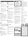
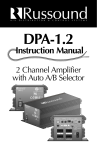
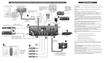
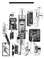
CONNECTION DIAGRAMS FOR RUSSOUND® MODEL A-KP2. REFER TO THE INSTRUCTIONS ON BACK. DIAGRAMS ARE NOT TO SCALE.
8
Multi-Source
Switch (SingleSource is default)
Speakers (8 Ohm)
3
Negative (–)
Functions in MultiSource Mode:
RLLINE OUT
BRGD *
MONO
R
STEREO
L+
GAIN
12V
TRIG
INPUT
Multi-Source
VIDEO
INPUT
SENSING
DELAY
5
1
4
2
3
12V TRIG
OUT 100mA
R
SPEAKER A OUT
AMPLIFIED INPUT
SENSING
4
WARNING : SHOCK
HAZARD – DO NOT OPEN
Single-Source
* FOR BRIDGED OPERATION
SEE MANUAL
A-KP2 REAR
AC
120V
60Hz
1.5A~
IR Confirmation &
Status LED
SPEAKER B OUT
5
DEFAULT
AMPLIFIED INPUT
External Amplifier (optional)
to speakers
IR Window
1
R
TV
4
R
SE
CBL
VC
3
STATUS
12VDC 100mA
110 punchdown
connectors
on A-KP2
PW
CE L
R
U RO
T
SO N
CO
2
A-BUS® Hub or A-BUS® Ready receiver
L
Left & Right
Volume Trim
6
R
EN
8
4
TE
M
3
4
4-ZONE, 1-SOURCE
SURFACE MOUNT AUDIO HUB
LINK
OUT
IN
CH
ST
UTE
2
KEYPAD OUTPUTS
IR CONFIRM
0
7
1
Wire order
9
5
1
R
NEWMARKET, NH U.S.A.
3
2
1
AUDIO
OUT
POWER
24VDC 2.5A
DESIGNED IN USA MADE IN KOREA
On/Off
TUP
3
AVIS : RISQUE DE CHOC
ELECTRIQUE – NES PAS
OUVRIR.
Volume Up/Down
7
R+
L
RLL+
SPEAKER OUT
SENSING
R+
LINE INPUT
L
A-KP2 Front
On/Off
All Off
Source Select
Positive (+)
4
LA
P
EE
SL
EX
T
IT
PU
SE
NU
ME
INFO
FF
ALL
O
O
VO
O
FF
4
CT
N
LE
E
L
SO
SE
URC
1
BLUE
LE
CT
GREEN
IDE
GU
ORANGE
VO
BROWN
IN
L
A-LRC1
L
AUDIO
IN
R
2
3
4
IR EMITTERS
A-H4
3
2
1
1
STATUS Disabled
6
J-Box
2
1 2 3 4 5 6 7 8
Decora®
faceplate
STATUS Enabled
RJ45 Wall Plate
(optional) located
near Hub
BLUE
BROWN
2
Underside of A-KP2
ORANGE
1
ORANGE
CAT-5
(behind wall)
GREEN
A-KP2
RJ45 CAT-5 patch cable
When wiring directly to Amplified Keypad,
use T568A RJ45 wire configuration
INSTRUCTIONS FOR CONNECTING AND USING RUSSOUND® MODEL A-KP2. REFER TO THE DIAGRAMS INSIDE.
INSTALLATION NOTES
• Before connecting the A-KP2:
- Make sure that the A-PS power supply is not connected to the
A-BUS® Hub or, if you are using an A-BUS® Ready receiver, that
the receiver is off.
- Make sure that the STATUS input on the A-BUS® Hub is not
connected.
• The recommended maximum length for use with standard
CAT-5 cable is 250 feet.
• Once all of the connections have been made, the A-PS power
supply can be connected to the A-BUS® Hub or, if you are using
an A-BUS® Ready receiver, the receiver may be turned on.
• Make any Volume Trim adjustments on the A-KP2 before
installing it into the wall.
1 CAT-5 CONNECTIONS
A CAT-5 cable is used to connect the A-KP2 to a keypad output on
an A-BUS® Hub or A-BUS® Ready receiver. For clean installations,
use RJ45 CAT-5 patch cables to connect from the Hub to an RJ45
Wall Plate (optional), and then wire from the Wall Plate to the
Amplified Control Module (see diagram). The Amplified Control
Modules have 110 punchdown connectors for the 8 individual conductors of the CAT-5 cable (use a punchdown tool with a 110 blade
to insert conductors).
NOTE: When wiring directly to an Amplified Control Module (i.e.,
not using an RJ45 Wall Plate) use T568A RJ45 wire configuration
for connection to the hub.
2 STATUS
The STATUS jumper is located on the underside of the A-KP2. All
A-BUS® components are shipped with the STATUS feature disabled.
If you intend to use the STATUS feature with your A-BUS® system,
you must enable the STATUS jumper on every Amplified Control
Module as well as on the A-BUS® Hub.
3 SPEAKER CONNECTIONS
Connect speaker wires to the speaker output terminals on the A-KP2
as shown in the diagram. The A-KP2 is designed for one pair of
8 Ohm speakers.
4 EXTERNAL AMPLIFIER (OPTIONAL)
An external amplifier can be connected to the LINE OUT of the
A-KP2 to provide more power in a large listening area, such as an
outdoor patio. The LINE OUT can also be used to feed a powered
subwoofer for extended bass response. This output is variably controlled by A-KP2 volume.
5 VOLUME TRIM
Two rotary trim potentiometers are located on the back of the A-KP2.
These can be used to set the maximum allowable volume level and to
adjust left/right balance. Use a Phillips-head screwdriver.
6 MOUNTING
Check all connections and test the system’s operation before installing
the A-KP2 into the wall. Using the included hardware, install the A-KP2
into a standard UL/CSA approved electrical J-Box as shown.
7 OPERATION
• Power On/Off source select and volume level can be controlled
using the buttons on the A-KP2 or by using the optional A-LRC1
remote control. The A-KP2 will always reset to a low volume level
when turned on.
• If you have installed IR Emitters in your A-BUS® system, then
sources can be operated with their own remote (or a “universal”
remote) by aiming it at the IR window on the A-KP2.
• When the A-KP2 receives infrared signals from a remote control,
the LED indicator will flash red.
• If your are using the STATUS feature in your A-BUS® system, the
LED indicator on the A-KP2 will illuminate green when your source
equipment is on, even when the A-KP2 is off.
8 MULTI-SOURCE MODE SWITCH
The Multi-Source Mode Switch should be set to Single-Source when
using the A-KP2 with Single-Source A-BUS® hubs. The Switch should
be set to Multi-Source when using the A-KP2 with Multi-Source
A-BUS® hubs.
A-KP2 OVERVIEW
English
Model A-KP2
with Multi-Source Select Capability
Amplified Keypad Module for A-BUS® System
Instruction Manual
Source Selection:
• Tapping the power button will allow you to toggle between multiple
sources once the initial press for power “on” is performed. The top 4
LEDs of the volume indicator will show the source that is selected.
The product you have just purchased is an integral part of the Russound®
A-BUS® Multi-Room Audio System. It is a component which, when combined
with other essential components and your source equipment (receiver, CD player, etc.), creates a versatile whole-house audio system that will fill your rooms
with high-quality sound for years to come.
A-BUS® technology is a new, innovative method of providing high quality audio
to remote locations with a single 8-conductor cable such as CAT-5.
A-BUS® technology provides many advantages over other methods of audio
distribution, including: simple, single CAT-5 wiring scheme; infrared control of
system components; infrared control of the optional A-KP2 amplified keypad
module; and system power status.
Every A-BUS® System is comprised of components from each of the following
three areas.
1. A-BUS® Amplified Control Modules: The Module contains both the amplifier for the room’s speakers as well as the control for those speakers. One
Module should be used for each room you choose to control. The
Russound® A-KP2 Amplified Keypad (with built-in IR receiver) and A-VC
Amplified Volume Control are examples of A-BUS® Amplified Control
Modules.
2. A-BUS® Hubs: All components of the A-BUS® system must be wired centrally to a Hub located near your source equipment. The Hub provides the
connection for source equipment, volume controls, infrared emitters and
power supply. The A-H484, A-H4, A-H4D, and A-H2 are examples of
A-BUS® Hubs. The A-H484, A-H4, and A-H2 are surface-mount units.
The A-H4D is an in-wall Decora® style unit.
3. Power Supply: The power supply plugs into the Hub. The Russound®
A-PS 24VDC/2.5A unit is an example.
A-KP2 03/03
A-BUS® is a registered trademark of LeisureTech Electronics Pty Ltd Australia
Decora® is a trademark of Leviton Corporation
Zone (Keypad) Off:
• Press and hold the power button until the keypad turns off.
System (Hub) Off:
• When the keypad is off, press and hold the power button until the
Green LED blinks Red and turns off.
Other Functions:
• Source selection and all other functions of the A-KP2 can be made
using the A-LRC1 hand-held remote.
IMPORTANT – Before installation, review the manuals included
with each component in your system. If you are unsure of any of
the installation procedures described herein or elsewhere, consult a
professional electronics installer.
A-BUS® SYSTEM OVERVIEW
9 MULTI-SOURCE OPERATION
5 Forbes Rd. Newmarket, NH 03857, USA
☎ 603.659.5170 • Fax 603.659.5388
e-mail: [email protected]
Come visit us at:
The A-KP2 is an in-wall, A-BUS® Amplified Keypad with push-buttons for speaker volume level and power On/Off source select as
well as an IR window for receiving remote control signals. The AKP2 connects to A-BUS® Hubs or A-BUS® Ready receivers using
CAT-5 wiring, and to loudspeakers using conventional speaker wire.
A-KP2 FEATURES
1)
2)
3)
4)
5)
6)
7)
8)
9)
Power On/Off source select button
Volume Up/Down buttons
Built-in IR receiver
IR control of volume and On/Off source select via optional
A-LRC1 remote
IR control of source components in an A-BUS® system that
uses IR Emitters
LED indicator for IR confirmation and source component
on/off status
Volume Trims for setting max. allowable level and L/R balance
Line Out for connecting to external amp or powered subwoofer
Decora® faceplate
A-KP2 SPECIFICATIONS
Output Impedance:
Input Impedance:
Power Requirements:
Status Input Reqs.:
CAT-5 Connection:
Dimensions (in-wall):
Weight:
C
8 Ohm per channel (1 pair of speakers)
28k Ohm min., line input
+24VDC, 750mA
+12VDC, 20mA
110 Punchdown
1.75"W x 2.875"H x 1.75"D (45x73x45mm)
6 oz. (170g)
US
Conforms to
UL 6500
Certified to
CAN/CSA
E65-94
Russound
A-KP2
Tested to Comply
with FCC Standards
FOR HOME OR OFFICE USE
LIMITED WARRANTY
The Russound® A-KP2 is fully guaranteed for Two (2) years from the date of purchase against
all defects in materials and workmanship. During this period Russound® will replace any
defective parts and correct any defect in workmanship without charge for either parts or
labor. For this warranty to apply, the unit must be installed and used according to its written instructions. If service is necessary, it must be performed by Russound®. The unit must
be returned to Russound® at the owner’s expense and with prior written permission.
Accidental damage and shipping damage are not considered defects under the terms of the
warranty. Russound® assumes no responsibility for defects resulting from abuse or servicing
performed by an agency or person not specifically authorized in writing by Russound®.
Damage to or destruction of components due to improper use voids the warranty. In these
cases the repair will be made at the owner’s expense. To return for repairs, the unit must be
shipped to Russound® at the owner’s expense, along with a note explaining the nature of the
service required. Be sure to pack in a corrugated container with at least 3 inches of resilient
material to protect the unit from damage in transit. Russound® products are sold only
through authorized Dealers and Distiributors to ensure that customers obtain proper support
and service. Any Russound® product purchased from an unauthorized dealer or other source,
including retailers, mail order sellers and online sellers will not be honored or serviced under
existing Russound® warranty policy. Any sale of products by an unauthorized source or other
manner not authorized by Russound® shall void the warranty on the applicable product.