1
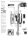
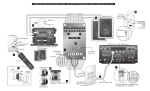
CONNECTION INSTRUCTIONS FOR A-K3. REFER TO NUMBERED DIAGRAM ON REVERSE.
1 RJ45 Connector for CAT-5 Connection
The RJ45 input provides a connection for the CAT-5 cable
from an A-BUS hub/controller to receive an audio signal,
passthrough IR and power over the CAT-5 cable. Use the
T568A wiring standard. The recommended maximum
length for standard CAT-5 cable is 150 feet.
Before connecting the A-K3, disconnect the power supply from the A-BUS hub/controller and disconnect the
Status power supply if used.
2 Line Out Connector for External Amplification
The Line Out provides a variable line-level audio output
connection for an external amplifier or powered subwoofer. An amplifier provides more power to a large
listening area, and a powered subwoofer adds extended
bass response.
Use 22AWG four conductor, two-pair twisted shielded
cable to connect to the Left positive (+) and negative (-),
and Right positive (+) and negative (-) screw down terminals on the back of the A-K3.
Terminate the four conductor two-twisted pair shielded
cable to the rear solder lugs of a wall plate fitted with
two RCA jacks on its front. Terminate the shield at the
Right negative (-) or Left negative (-) ring of the solder
lugs. RCA cables can be used to connect the amp or subwoofer to the wall place for audio signal feed.
3 Speaker Output Connector for Speakers
The Speaker Output connections provide speaker-level
audio output for a pair of 8-ohm speakers. The screwdown terminals accepts up to 16 gauge speaker wire.
4 Status Jumper for Status LED Enable/Disable
The Status option provides visual indication when source
equipment is powered on. With this option enabled, the
status LED shows green on the keypad when the system
is on (keypad can be on or off).
To enable the Status LED, locate the status pins on the
right side of the keypad under the faceplate. Place the
status jumper over the bottom two pins to enable the
status LED.
Note: Amplified keypads are shipped with the Status LED
option disabled (default).
5 Source Mode Jumper for Single/Multisource
The single/multisource jumpers set the A-K3 to be used
with either single- or multi-source A-BUS hubs/controllers. The jumpers and pins are located under the faceplate on the right side of the keypad (facing front).
The pins are jumpered to select between 1, 4 and 6
sources. 1 source = no jumper; 4 sources = top two pins
jumpered; 6 sources = bottom two pins jumpered.
6 Gain Control for Maximum Levels
The two rotary trim potentiometers on the side of the
A-K3 provide adjustment of audio gain. These are used to
set the maximum allowable volume for the left and right
speakers connected to the A-K3.
7 Keypad Connection to A-C68 Controller
Each keypad connects to a Keypad Output port on the
back of the A-C68 controller. Connections are made using
CAT-5 cable with an RJ45 connector.
The Keypad Ports are located on the back of the A-C68
on the left. Connections at the Keypad Ports are made
with RJ45 connectors using T568A CAT-5 wire configuration. CAT-5 cable length should be no longer than 150
feet from controller to keypad.
If used in a system with A-K5L keypads, when connecting
A-K3 keypads to the A-C68, the keypad dip switches on
the controller’s front programming center must be set in
the UP position. Dip switches correspond to numbered
keypad ports.
If used in a A-C68 system with no A-K5L keypads, set the
keypad dip switches in the UP position.
For a clean installation when wiring from a Keypad Port,
use an RJ45 CAT-5 patch cable to connect from the keypad port to an RJ-45 wall plate (optional). Using the same
RJ45 T568A CAT-5 wiring configuration, use CAT-5 from
the RJ45 wall plate to the keypad.
8 Installation
Check all connections and test the system’s operation
before installing the A-K3 into the wall. Using the included hardware, install the A-K3 into a standard UL/CSA
single-gang electrical J-box.
Status function and operation:
When the source is powered on, the Status circuit is
powered by 12VDC and turns the keypad’s status LED to
green. This indicates to the user that the source is on and
ready to receive remote control commands.
When the source is powered off (remotely or manually),
it shuts off the 12VDC Status power connected to it, and
turns off all the interfaces connected to the controller
(green LED off).
Copyright © 2007 Russound® All rights reserved. All trademarks are property of their respective owners. Russound is not
responsible for typographical errors or omissions. Specifications
subject to change without notice.
Safety Instructions
1.
Read Instructions - All the safety and operating instructions should
be read before the appliance is operated.
2.
Retain Instructions - The safety and operating instructions should
be retained for future reference.
3.
Heed Warnings - All warnings on the appliance in the operating
instructions should be adhered to.
4.
Follow Instructions - Follow all operating and user instructions.
5.
Water and Moisture - The appliance should not be used near water;
for example, near a bathtub, washbowl, kitchen sink, laundry tub, in
a wet basement, or near a swimming pool.
6.
Wall or Ceiling Mounting - The appliance should be mounted to a
wall or ceiling only as recommended by the manufacturer.
7.
Heat - The appliance should be situated away from heat sources
such as radiators, heat registers, stoves, or other appliances (including amplifiers) that produce heat.
8.
Power Sources - The appliance should be connected to a power
supply only of the type described in the operating instructions or as
marked on the appliance.
9.
Grounding or Polarization - Precaution should be taken so that the
grounding or polarization means of an appliance is not defeated.
10. Object and Liquid Entry - Care should be taken so that objects do
not fall and liquids are not spilled into the enclosure through the
openings.
11. Damage Requiring Service - The appliance should be serviced by
qualified service personnel when:
The power supply cord or the plug has been damaged;
Objects have fallen, liquid has been spilled into the appliance;
The appliance has been exposed to rain;
The appliance does not appear to operate normally; or
The appliance has been dropped or the enclosure is damaged.
12. Servicing - The user should not attempt to service the appliance
beyond that described in the operating instructions. All other servicing should be referred to qualified service personnel.
13. Care – From time to time you should wipe off the front panel with a
soft dry cloth.
Limited Warranty
The Russound A-K3 is fully guaranteed for two (2) years from the date of purchase
against all defects in materials and workmanship. During this period Russound will
replace any defective parts and correct any defect in workmanship without charge
for either parts or labor. For this warranty to apply, the unit must be installed and used
according to its written instructions. If service is necessary, it must be performed by
Russound. Russound assumes no responsibility for defects resulting from abuse or
servicing performed by an agency or person not specifically authorized in writing by
Russound. Damage to or destruction of components due to improper use voids the
warranty. In these cases the repair will be made at the owner’s expense. Accidental
damage and shipping damage are not considered defects under the terms of the
warranty. To return for repairs, the unit must be shipped to Russound at the owner’s
expense, along with a Return Authorization number and documentation explaining
the nature of the service required. Any product returned without prior written permission will be returned to sender. Russound sells products only through authorized
Dealers and Distributors to ensure that customers obtain proper support and service.
Any Russound product purchased from an unauthorized dealer or other source,
including retailers, mail order sellers and online sellers will not be honored or serviced
under existing Russound warranty policy. Any sale of products by an unauthorized
source or other manner not authorized by Russound shall void the warranty on the
applicable product.
5 Forbes Rd., Newmarket, NH 03857, USA
Tel 603.659.5170 • Fax 603.659.5388
e-mail: [email protected]
28-1258 10/19/07
A-K3
Amplified Keypad with Multisource Capability
for A-BUS® System
Installation Manual
A-K3 Overview
The Russound A-K3 is an in-wall amplified keypad used
with A-BUS hubs and controllers in a distributed audio
system. It can be used with both single- and multi-source
A-BUS hubs/controllers. The A-K3 provides source selection and control with backlit push buttons, plus an IR
window to receive remote control signals.
The volume up/down buttons control the speakers in
the room that are connected to the A-K3. Typical installations place one A-K3 in each room of the A-BUS system.
The Line Out connection on the A-K3 can be used to
feed a separate powered subwoofer or to connect an
external amplifier for more power to a larger listening
area.
A-K3 Key Features
•
•
•
•
•
Power On/Off button (acts as source select with
multi-source hubs/controllers)
Volume trims for L/R balance and maximum level
settings
Built-in IR receiver with IR confirmation LED
IR control of settings and sources via A-LRC2 optional
remote
Line Out connection for external amp or powered
subwoofer
A-K3 Specifications
Output Impedance:
Input Impedance:
Power Requirements:
CAT-5 Connections:
Dimensions (in-wall):
Weight:
8 ohms/channel (1 pair speakers)
10 kohms
+24VDC 660mA peak
RJ45
1.75”W x 2.875”H x 1.75”D
(45x73x45mm)
5.5oz. (160g)
A-BUS is a registered trademark of LeisureTech Electronics Pty
Ltd Australia
This product may be covered by one or more of the following
patents: US #7,181,023, #6,389,139; EP #1004222,
AU #739808, NZ #502982, Mexico #241196, Canada #CA2301062
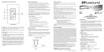
A-K3 Keypad Front Panel Operation
CONNECTION DIAGRAM FOR A-K3. REFER TO THE NUMBERED INSTRUCTIONS ON REVERSE. DIAGRAMS ARE NOT TO SCALE.
RCA
Cable
Mute In Page
In
Page
Trim
5
6
7
8
Common IR
IR
In
1
Out
IR
R
Src Trim
In
2
Out
IR
R
Src Trim
In
3
Out
IR
In
R
Src Trim
4
Out
IR
R
Src Trim
In
5
Out
IR
R
Src Trim
In
6
Out
R
Src Trim
12VDC
L
In Control Link Out
1
1
2
3
Outputs to Keypads
4
Trigger Out
100mA
L
L
L
L
Source Audio Connections
A-C68 (back)
22AWG
2 pair
twisted
shielded
cable
CAT-5
cable
1
2
L
2
R235LS Amplifier
Speakers
6
5
3
4
1
2
VOLUME UP/DOWN - Raises/lowers room volume
3
STATUS LED - Green LED lights to show Status “on” and
turns off when Status is “off”
4
IR CONFIRMATION LED - Red LED blinks to confirm IR
signal reception.
5
IR RECEIVER - Receives IR signals from a remote
control. Source components attached to IR emitters
in an A-BUS system can be controlled with their own
remote controls or A-LRC2 learning remote aimed at
the A-K3.
6
1
2
Source
jumper
VOLUME LEVEL - Volume level indicator LEDs light up
from bottom to top to indicate volume level. Also
indicates source selected (1-6) when in “multi-source”
mode.
POWER - Turns zone ON when pressed once. (In multisource mode, when ON, press and hold will turn zone
OFF. When OFF, press and hold will turn OFF all zones.)
Status LED remains lit when keypad/zone is OFF if any
other zone in system is ON.
SOURCE SELECT (Multisource controller) - When the
keypad is set in “Multisource” mode, the power button
is used to toggle through and select a source. Tap the
power button to toggle between 1 and 6 multiple
sources (once power is on). The top LEDs of the volume
indicator show (from top to bottom) the source that is
selected (top LED is source 1, next LED down is
source 2, etc).
++
++
5
L GAIN R
6
Hub
4
1
6
4
3
Status
jumper
NO LED
LED
A-K3 (side)
A-K3 (back)
A-K3 (front)
A-C68 (front)
Firmware Update
Run
Keypad Dip Switches
1 2 3 4 5 6 7 8
Update
Speaker cable
8-ohm speakers
7
IR In
Source/
Test
Cmd/
Type
Code/
Key
IR Learn
Setup
Num Src Fact Init
Keypad Dip Switches
1 2 3 4 5 6 7 8
Keypad dip switch on A-C68
set in DOWN position