1
SUPER
®
SUPERSERVER 5015B-MT
USER’S MANUAL
Revision 1.0
The information in this User’s Manual has been carefully reviewed and is believed to be accurate.
The vendor assumes no responsibility for any inaccuracies that may be contained in this document,
makes no commitment to update or to keep current the information in this manual, or to notify any
person or organization of the updates. Please Note: For the most up-to-date version of this
manual, please see our web site at www.supermicro.com.
Super Micro Computer, Inc. ("Supermicro") reserves the right to make changes to the product
described in this manual at any time and without notice. This product, including software, if any,
and documentation may not, in whole or in part, be copied, photocopied, reproduced, translated or
reduced to any medium or machine without prior written consent.
IN NO EVENT WILL SUPERMICRO BE LIABLE FOR DIRECT, INDIRECT, SPECIAL, INCIDENTAL,
SPECULATIVE OR CONSEQUENTIAL DAMAGES ARISING FROM THE USE OR INABILITY TO
USE THIS PRODUCT OR DOCUMENTATION, EVEN IF ADVISED OF THE POSSIBILITY OF
SUCH DAMAGES. IN PARTICULAR, SUPERMICRO SHALL NOT HAVE LIABILITY FOR ANY
HARDWARE, SOFTWARE, OR DATA STORED OR USED WITH THE PRODUCT, INCLUDING THE
COSTS OF REPAIRING, REPLACING, INTEGRATING, INSTALLING OR RECOVERING SUCH
HARDWARE, SOFTWARE, OR DATA.
Any disputes arising between manufacturer and customer shall be governed by the laws of Santa
Clara County in the State of California, USA. The State of California, County of Santa Clara shall
be the exclusive venue for the resolution of any such disputes. Super Micro's total liability for
all claims will not exceed the price paid for the hardware product.
FCC Statement: This equipment has been tested and found to comply with the limits for a Class
A digital device pursuant to Part 15 of the FCC Rules. These limits are designed to provide
reasonable protection against harmful interference when the equipment is operated in a commercial
environment. This equipment generates, uses, and can radiate radio frequency energy and, if not
installed and used in accordance with the manufacturer’s instruction manual, may cause harmful
interference with radio communications. Operation of this equipment in a residential area is likely
to cause harmful interference, in which case you will be required to correct the interference at your
own expense.
California Best Management Practices Regulations for Perchlorate Materials: This Perchlorate
warning applies only to products containing CR (Manganese Dioxide) Lithium coin cells. “Perchlorate
Material-special handling may apply. See www.dtsc.ca.gov/hazardouswaste/perchlorate”
WARNING: Handling of lead solder materials used in this
product may expose you to lead, a chemical known to
the State of California to cause birth defects and other
reproductive harm.
Manual Revision 1.0
Release Date: February 7, 2008
Unless you request and receive written permission from Super Micro Computer, Inc., you may not
copy any part of this document.
Information in this document is subject to change without notice. Other products and companies
referred to herein are trademarks or registered trademarks of their respective companies or mark
holders.
Copyright © 2008 by Super Micro Computer, Inc.
All rights reserved.
Printed in the United States of America
Preface
Preface
About This Manual
This manual is written for professional system integrators and PC technicians. It provides information for the installation and use of the SuperServer 5015B-MT. Installation and maintainance should be performed by experienced technicians only.
The SuperServer 5015B-MT is a high-end single processor 1U rackmount server
based on the SC813MTQ-300C server chassis and the X7SBi motherboard. The
X7SBi supports single Intel® Xeon® 3000 Series/3200 Series Processor at system
bus speeds of 1333/1066/800 MHz.
Manual Organization
Chapter 1: Introduction
The first chapter provides a checklist of the main components included with the
server system and describes the main features of the Super X7SBi motherboard
and the SC813MTQ-300C chassis.
Chapter 2: Server Installation
This chapter describes the steps necessary to install the SuperServer 5015B-MT
into a rack and check out the server configuration prior to powering up the system. If
your server was ordered without the processor and memory components, this chapter will refer you to the appropriate sections of the manual for their installation.
Chapter 3: System Interface
Refer to this chapter for details on the system interface, which includes the functions
and information provided by the control panel on the chassis as well as other LEDs
located throughout the system.
iii
SUPERSERVER 5015B-MT User's Manual
Chapter 4: System Safety
You should thoroughly familiarize yourself with this chapter for a general overview
of safety precautions that should be followed when installing and servicing the
SuperServer 5015B-MT.
Chapter 5: Advanced Motherboard Setup
Chapter 5 provides detailed information on the X7SBi motherboard, including the
locations and functions of connectors, headers and jumpers. Refer to this chapter
when adding or removing processors or main memory and when reconfiguring the
motherboard.
Chapter 6: Advanced Chassis Setup
Refer to Chapter 6 for detailed information on the SC813MTQ-300C 1U rackmount
server chassis. You should follow the procedures given in this chapter when installing, removing or reconfiguring Serial ATA or peripheral drives and when replacing
system power supply units and cooling fans.
Chapter 7: BIOS
The BIOS chapter includes an introduction to BIOS and provides detailed information on running the CMOS Setup Utility.
Appendix A: BIOS POST Messages
Appendix B: BIOS POST Codes
Appendix C: System Specifications
iv
Preface
Notes
v
SUPERSERVER 5015B-MT User's Manual
Table of Contents
Chapter 1 Introduction
1-1
Overview ......................................................................................................... 1-1
1-2
Motherboard Features ..................................................................................... 1-2
Processor ........................................................................................................ 1-2
Memory ........................................................................................................... 1-2
Onboard SATA................................................................................................. 1-2
PCI Expansion Slots ....................................................................................... 1-2
Onboard Controllers/Ports .............................................................................. 1-2
1-3
Server Chassis Features ................................................................................ 1-4
System Power ................................................................................................. 1-4
Control Panel .................................................................................................. 1-4
Rear I/O Panel ................................................................................................ 1-4
1-4
Contacting Supermicro .................................................................................... 1-5
Chapter 2 Server Installation
2-1
Overview ......................................................................................................... 2-1
2-2
Unpacking the System .................................................................................... 2-1
2-3
Preparing for Setup ......................................................................................... 2-1
Choosing a Setup Location ............................................................................. 2-1
Rack Precautions ............................................................................................ 2-2
Server Precautions.......................................................................................... 2-2
Rack Mounting Considerations ....................................................................... 2-3
Ambient Operating Temperature ................................................................ 2-3
Reduced Airflow ......................................................................................... 2-3
Mechanical Loading ................................................................................... 2-3
Circuit Overloading ..................................................................................... 2-3
Reliable Ground ......................................................................................... 2-3
2-4
Installing the System into a Rack ................................................................... 2-4
Identifying the Sections of the Rack Rails ...................................................... 2-4
Installing the Rear Inner Rails ........................................................................ 2-4
Installing the Rack Rails ................................................................................. 2-5
Installing the Server into the Rack .................................................................. 2-6
Installing the Server into a Telco Rack ........................................................... 2-7
2-5
Checking the Motherboard Setup ................................................................... 2-8
2-6
Checking the Drive Bay Setup ........................................................................ 2-9
vi
Table of Contents
Chapter 3 System Interface
3-1
Overview ......................................................................................................... 3-1
3-2
Control Panel Buttons ..................................................................................... 3-1
Reset ............................................................................................................... 3-1
Power .............................................................................................................. 3-1
3-3
Control Panel LEDs ........................................................................................ 3-2
Overheat/Fan Fail ........................................................................................... 3-2
NIC2 ................................................................................................................ 3-2
NIC1 ................................................................................................................ 3-2
HDD................................................................................................................. 3-2
Power .............................................................................................................. 3-3
3-4
SATA Drive Carrier LEDs ................................................................................ 3-3
Chapter 4 System Safety
4-1
Electrical Safety Precautions .......................................................................... 4-1
4-2
General Safety Precautions ............................................................................ 4-2
4-3
ESD Precautions ............................................................................................. 4-3
4-4
Operating Precautions .................................................................................... 4-4
Chapter 5 Advanced Serverboard Setup
5-1
Handling the Serverboard ............................................................................... 5-1
Precautions ..................................................................................................... 5-1
Unpacking ....................................................................................................... 5-2
5-2
Serverboard Installation .................................................................................. 5-2
5-3
Connecting Cables .......................................................................................... 5-3
Connecting Data Cables ................................................................................. 5-3
Connecting Power Cables .............................................................................. 5-3
Connecting the Control Panel ......................................................................... 5-3
5-4
I/O Ports .......................................................................................................... 5-4
5-5
Installing the Processors and Heat Sinks ....................................................... 5-5
5-6
Installing Memory ............................................................................................ 5-8
Memory Support .............................................................................................. 5-8
5-7
Adding PCI Add-On Cards .............................................................................. 5-9
5-8
Serverboard Details ...................................................................................... 5-10
X7SBi Quick Reference .................................................................................5-11
5-9
Connector Definitions ................................................................................... 5-12
5-10
Jumper Settings ............................................................................................ 5-17
5-11
Onboard Indicators........................................................................................ 5-19
5-12
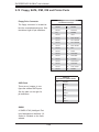
Floppy, SATA, IPMI, IDE and Printer Ports................................................... 5-20
5-13
Installing Drivers............................................................................................ 5-22
vii
SUPERSERVER 5015B-MT User's Manual
Chapter 6 Advanced Chassis Setup
6-1
Static-Sensitive Devices .................................................................................. 6-1
Precautions ..................................................................................................... 6-1
Unpacking ....................................................................................................... 6-1
6-2
Control Panel .................................................................................................. 6-2
6-3
System Fans ................................................................................................... 6-3
6-4
Drive Bay Installation/Removal ....................................................................... 6-3
Removing the Front Bezel .............................................................................. 6-3
Serial ATA Drive Installation ............................................................................ 6-4
Accessing the Drive Bays ............................................................................... 6-4
Serial ATA Backplane ...................................................................................... 6-5
6-5
Power Supply .................................................................................................. 6-7
Power Supply Failure ...................................................................................... 6-7
Chapter 7 BIOS
7-1
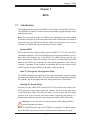
Introduction...................................................................................................... 7-1
7-2
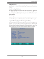
Running Setup ................................................................................................ 7-2
7-3
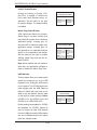
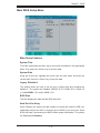
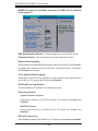
Main BIOS Setup ............................................................................................ 7-2
7-4
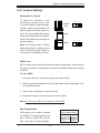
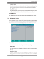
Advanced Setup .............................................................................................. 7-7
7-5
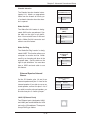
Security Settings ........................................................................................... 7-23
7-6
Boot Settings ................................................................................................. 7-25
7-7
Exit ................................................................................................................ 7-26
Appendix A BIOS POST Messages
Appendix B BIOS POST Codes
Appendix C System Specifications
viii
Chapter 1: Introduction
Chapter 1
Introduction
1-1
Overview
The Supermicro SuperServer 5015B-MT is a high-end single processor, 1U rackmount server with state-of-the-art features. The 5015B-MT is comprised of two main
subsystems: the SC813MTQ-300C 1U chassis and the X7SBi motherboard. Please
refer to our web site for information on operating systems that have been certified
for use with the 5015B-MT.
In addition to the mainboard and chassis, various hardware components may have
been included with the 5015B-MT, as listed below.
One CPU heatsink (SNK-P0016P)
One (1) slim DVD-ROM drive [DVM-PNSC-824(B)]
Four (4) 4-cm fans (FAN-0061L)
One (1) air shroud (MCP-310-81201-0B)
Serial ATA (SATA) Accessories:
One (1) internal SATA backplane (BPN-SAS-815TQ)
One (1) set of SATA cables (CBL-0186L)
One (1) SGPIO cable (CBL-0157L)
Four (4) SATA drive carriers [CSE-PT39 (B)]
One (1) PCI-E x8 slot riser card (CSE-RR1U-ELi)
One (1) 64-bit PCI-X slot riser card (CSE-RR1U-Xi)
Rackmount hardware with screws (CSE-PT52)
One (1) CD containing drivers and utilities
SuperServer 5015B-MT User's Manual
Note: "B" indicates black.
1-1
SUPERSERVER 5015B-MT User's Manual
1-2
Motherboard Features
At the heart of the SuperServer 5015B-MT lies the X7SBi, a single processor
motherboard based upon Intel's E3210 chipset. Below are the main features of
the X7SBi.
Processor
The X7SBi supports single Intel Xeon 3200/3000 Series LGA775 processors at
system bus speeds of 1333, 1066 and 800 MHz. Please refer to the motherboard
specifications pages on our web site for updates on supported processors.
Memory
The X7SBi has four 240-pin DIMM slots that can support up to 8 GB of unbuffered
ECC DDR2-800/667 SDRAM.
Onboard SATA
A SATA controller is built in to the ICH9R portion of the chipset to provide support
for a six port, 3 Gb/sec Serial ATA subsystem, which is RAID 0, 1, 5 and 10 supported. The SATA drives are hot-swappable units. Note: The operating system
you use must have RAID support to enable the hot-swap capability and RAID
function of the SATA drives.
PCI Expansion Slots
The X7SBi has one universal PCI-Express x8 slot, one 64-bit 133 MHz PCI-X slot
and one PCI 33 MHz slot. Either the PCI-E slot or the PCI-X slot may be populated
with the use of a riser card (included).
Onboard Controllers/Ports
An onboard IDE controller supports one floppy drive and up to two Ultra ATA 100
hard drives or ATAPI devices. Onboard I/O backpanel ports include one COM port,
a VGA port, two USB ports, PS/2 mouse and keyboard ports and two Gigabit LAN
(NIC) ports.
Other Features
Other onboard features that promote system health include voltage monitors, a
chassis intrusion header, auto-switching voltage regulators, chassis and CPU
overheat sensors, virus protection and BIOS rescue.
1-2
Chapter 1: Introduction
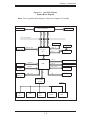
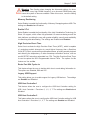
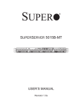
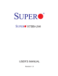
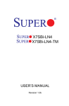
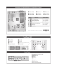
Figure 1-1 . Intel 3210 Chipset:
System Block Diagram
Note: This is a general block diagram. Please see Chapter 5 for details.
LGA775_PROCESSOR
VRM 11
CK505 CLK
ADDR
CTRL
DATA
ADDR
CTRL
DATA
FSB: 1333/1066/800
DIMM_CHA
DIMM_CHB
PCIE_x 8
1xPCIX_64
PCIE_x 8
DDR2_667/800
PCI- X B US
Intel 3210
MC H
PX H - V
PCIE_x 8
DMI
PCIE_x1
PRI_IDE
6 x SATA
PORTS
ICH9R
PCIE_x1
USB 2.0/1.1
MS.
FDD.
GLAN1 82573V
ATI-ES1000
LPC
W83627DHG
LPC I/O
KB.
GLAN2 82573L
PCI_32_BUS
S-ATA/300
LPC
USB
PORTS_0~7
UDMA/100
FWH
IPMI I/F
SER.1
SER.2
PRINTER
1-3
IPMI
SUPERSERVER 5015B-MT User's Manual
1-3
Server Chassis Features
The following is a general outline of the main features of the SC813MTQ-300C
chassis.
System Power
When configured as a SuperServer 5015B-MT, the SC813MTQ-300C chassis includes a single 300W power supply.
Serial ATA Subsystem
For the 5015B-MT, the SC813MT-300 chassis was designed to support four Serial
ATA hard drives, which are hot-swappable units.
Note: The operating system you use must have RAID support to enable the hotswap capability of the Serial ATA drives.
Control Panel
The SC813MTQ-300C's control panel provides important system monitoring and
control information. LEDs indicate power on, network activity, hard disk drive activity and system overheat conditions. The control panel also includes a main power
button and a system reset button. The front of the SC813MTQ-300C also includes
a COM port and two USB serial ports for easy access.
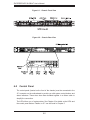
Rear I/O Panel
The SC813MTQ-300C is a 1U rackmount chassis. Its I/O panel provides one PCI
motherboard expansion slot, one COM port (another is internal), two USB ports,
a parallel (printer) port, PS/2 mouse and keyboard ports, a VGA port and two Gb
Ethernet ports.
Cooling System
The SC813MTQ-300C chassis has an innovative cooling design that features three
4-cm high-performance system cooling fans. Each of these fans plug into a chassis
fan header on the motherboard. An air shroud channels the airflow generated by
the fans to efficiently cool the processor area of the system.
A fan speed control setting in BIOS allows fan speed to be determined by system
temperature [the recommended setting is 3-pin (Server)].
1-4
Chapter 1: Introduction
1-4
Contacting Supermicro
Headquarters
Address:
Super Micro Computer, Inc.
980 Rock Ave.
San Jose, CA 95131 U.S.A.
Tel:
+1 (408) 503-8000
Fax:
+1 (408) 503-8008
Email:
[email protected] (General Information)
[email protected] (Technical Support)
Web Site:
www.supermicro.com
Europe
Address:
Super Micro Computer B.V.
Het Sterrenbeeld 28, 5215 ML
's-Hertogenbosch, The Netherlands
Tel:
+31 (0) 73-6400390
Fax:
+31 (0) 73-6416525
Email:
[email protected] (General Information)
[email protected] (Technical Support)
[email protected] (Customer Support)
Asia-Pacific
Address:
Super Micro Computer, Taiwan
4F, No. 232-1, Liancheng Rd.
Chung-Ho 235, Taipei County
Taiwan, R.O.C.
Tel:
+886-(2) 8226-3990
Fax:
+886-(2) 8226-3991
Web Site:
www.supermicro.com.tw
Technical Support:
Email:
[email protected]
Tel:
886-2-8228-1366, ext.132 or 139
1-5
SUPERSERVER 5015B-MT User's Manual
Notes
1-6
Chapter 2: Server Installation
Chapter 2
Server Installation
2-1
Overview
This chapter provides a quick setup checklist to get your SuperServer 5015B-MT
up and running. Following the steps in the order given should enable you to have
the system operational within a minimal amount of time. This quick setup assumes
that your 5015B-MT system has come to you with the processor and memory preinstalled. If your system is not already fully integrated with a motherboard, processor,
system memory etc., please turn to the chapter or section noted in each step for
details on installing specific components.
2-2
Unpacking the System
You should inspect the box the SuperServer 5015B-MT was shipped in and note
if it was damaged in any way. If the server itself shows damage, you should file a
damage claim with the carrier who delivered it.
Decide on a suitable location for the rack unit that will hold the SuperServer 5015BMT. It should be situated in a clean, dust-free area that is well ventilated. Avoid
areas where heat, electrical noise and electromagnetic fields are generated. You
will also need it placed near a grounded power outlet. Read the Rack and Server
Precautions in the next section.
2-3
Preparing for Setup
The box the SuperServer 5015B-MT was shipped in should include two sets of
rail assemblies, six rail mounting brackets and the mounting screws you will need
to install the system into the rack. Follow the steps in the order given to complete
the installation process in a minimal amount of time. Please read this section in
its entirety before you begin the installation procedure outlined in the sections that
follow.
Choosing a Setup Location
•
Leave enough clearance in front of the rack to enable you to open the front door
completely (~25 inches) and approximately 30 inches of clearance in the back
of the rack to allow for sufficient airflow and ease in servicing.This product is for
2-1
SUPERSERVER 5015B-MT User's Manual
installation only in a Restricted Access Location (dedicated equipment rooms,
service closets and the like).
•
This product is not suitable for use with visual display work place devices
acccording to §2 of the the German Ordinance for Work with Visual Display
Units.
!
Warnings and Precautions!
!
Rack Precautions
•
•
•
•
Ensure that the leveling jacks on the bottom of the rack are fully extended to
the floor with the full weight of the rack resting on them.
In single rack installation, stabilizers should be attached to the rack. In multiple
rack installations, the racks should be coupled together.
Always make sure the rack is stable before extending a component from the
rack.
You should extend only one component at a time - extending two or more simultaneously may cause the rack to become unstable.
Server Precautions
•
•
•
•
•
•
Review the electrical and general safety precautions in Chapter 4.
Determine the placement of each component in the rack before you install the
rails.
Install the heaviest server components on the bottom of the rack first, and then
work up.
Use a regulating uninterruptible power supply (UPS) to protect the server from
power surges, voltage spikes and to keep your system operating in case of a
power failure.
Allow the hot plug SATA drives and power supply modules to cool before touching them.
Always keep the rack's front door and all panels and components on the servers
closed when not servicing to maintain proper cooling.
2-2
Chapter 2: Server Installation
Rack Mounting Considerations
Ambient Operating Temperature
If installed in a closed or multi-unit rack assembly, the ambient operating temperature of the rack environment may be greater than the ambient temperature of the
room. Therefore, consideration should be given to installing the equipment in an
environment compatible with the manufacturer’s maximum rated ambient temperature (Tmra).
Reduced Airflow
Equipment should be mounted into a rack so that the amount of airflow required
for safe operation is not compromised.
Mechanical Loading
Equipment should be mounted into a rack so that a hazardous condition does not
arise due to uneven mechanical loading.
Circuit Overloading
Consideration should be given to the connection of the equipment to the power
supply circuitry and the effect that any possible overloading of circuits might have
on overcurrent protection and power supply wiring. Appropriate consideration of
equipment nameplate ratings should be used when addressing this concern.
Reliable Ground
A reliable ground must be maintained at all times. To ensure this, the rack itself
should be grounded. Particular attention should be given to power supply connections other than the direct connections to the branch circuit (i.e. the use of power
strips, etc.).
2-3
SUPERSERVER 5015B-MT User's Manual
2-4
Installing the System into a Rack
This section provides information on installing the SuperServer 5015B-MT into a
rack unit with the rack rails provided. If the server has already been mounted into
a rack, you can skip ahead to Sections 2-5 and 2-6.
There are a variety of rack units on the market, which may mean the assembly
procedure will differ slightly. You should also refer to the installation instructions that
came with the rack unit you are using.
Identifying the Sections of the Rack Rails
You may have received rack rail hardware with the SuperServer 5015B-MT. (Two
front inner rails should already be attached to the chassis.) This hardware consists
of two rear inner rails that secure to the chassis, one on each side just behind the
preinstalled front inner rails. Note that these two rails are left/right specific.
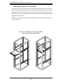
Installing the Rear Inner Rails
First, locate the right rear inner rail (the rail that will be used on the right side of
the chassis when you face the front of the chassis). Align the two square holes on
the rail against the hooks on the right side of the chassis. Securely attach the rail
to the chassis with M4 flat head screws. Repeat these steps to install the left rear
inner rail to the left side of the chassis (see Figure 2-1). You will also need to attach
the rail brackets when installing into a telco rack.
Locking Tabs: Both chassis rails have a locking tab, which serves two functions.
The first is to lock the server into place when installed and pushed fully into the
rack, which is its normal position. Secondly, these tabs also lock the server in place
when fully extended from the rack. This prevents the server from coming completely
out of the rack when you pull it out for servicing.
2-4
Chapter 2: Server Installation
Figure 2-1. Installing Rear Inner Chassis Rails
Installing the Rack Rails
Determine where you want to place the SuperServer 5015B-MT in the rack (see
Rack and Server Precautions in Section 2-3). Position the chassis rail guides at the
desired location in the rack, keeping the sliding rail guide facing the inside of the
rack. Screw the assembly securely to the rack using the brackets provided. Attach
the other assembly to the other side of the rack, making sure that both are at the
exact same height and with the rail guides facing inward.
2-5
SUPERSERVER 5015B-MT User's Manual
Installing the Server into the Rack
You should now have rails attached to both the chassis and the rack unit. The next
step is to install the server into the rack. Do this by lining up the rear of the chassis
rails with the front of the rack rails. Slide the chassis rails into the rack rails, keeping
the pressure even on both sides (you may have to depress the locking tabs when
inserting). See Figure 2-2.
When the server has been pushed completely into the rack, you should hear the
locking tabs "click".
Figure 2-2. Installing the Server into a Rack
(with optional front bezel shown)
2-6
Chapter 2: Server Installation
Installing the Server into a Telco Rack
To install the SuperServer 5015B-MT into a Telco type rack, use two L-shaped
brackets on either side of the chassis (four total). First, determine how far the server
will extend out the front of the rack. Larger chassis should be positioned to balance
the weight between front and back. If a bezel is included on your server, remove
it. Then attach the two front brackets to each side of the chassis, then the two rear
brackets positioned with just enough space to accommodate the width of the rack.
Finish by sliding the chassis into the rack and tightening the brackets to the rack.
Figure 2-3. Installing the Server into a Telco Rack
(with optional front bezel shown)
2-7
SUPERSERVER 5015B-MT User's Manual
2-5
Checking the Motherboard Setup
After you install the 5015B-MT in the rack, you will need to open the unit to make
sure the motherboard is properly installed and all the connections have been
made.
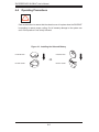
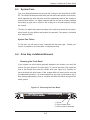
Accessing the Inside of the System
1. Grasp the two handles on either side and pull the unit straight out until it
locks (you will hear a "click").
2. Depress the two buttons on the top of the chassis to release the top cover.
There is a large rectangular recess in the middle front of the top cover to help
you push the cover away from you until it stops.
3. Lift the top cover from the chassis to gain full access to the inside of the
server. See Figure 2-4.
Checking the Components
1. You may have the processor already installed into the system board. The
processor should have its own heatsink attached. See Chapter 5 for instructions on processor installation.
2. Your 5015B-MT server system may have come with system memory already
installed. Make sure all DIMMs are fully seated in their slots. For details on
adding system memory, refer to Chapter 5.
3. If desired, you can install an add-on card to the system. See Chapter 5 for
details on installing a PCI add-on card.
4. Make sure all power and data cables are properly connected and not blocking
the airflow. See Chapter 5 for details on cable connections.
2-8
Chapter 2: Server Installation
Figure 2-4.
Accessing the Inside of the SuperServer 5015B-MT
2-6
Checking the Drive Bay Setup
Next, you should check to make sure the peripheral drives and the SATA drives
and SATA backplane have been properly installed and all essential connections
have been made.
Checking the Drives
1. All drives can be accessed from the front of the server. For servicing the
CD-ROM drive, you will need to remove the top chassis cover. The SATA
disk drives can be installed and removed from the front of the chassis without
removing the top chassis cover.
2. Refer to Chapter 6 if you need to reinstall a CD-ROM drive to the system.
3. Depending upon your system's configuration, your system may have one or
more SATA drives already installed. If you need to install SATA drives, please
refer to the appropriate section in Chapter 6.
Checking the Airflow
1. Airflow is provided by four high-performance 4-cm input fans. The system
component layout was carefully designed to promote sufficient airflow through
the small 1U rackmount space.
2-9
SUPERSERVER 5015B-MT User's Manual
2. Also note that all power and data cables have been routed in such a way that
they do not block the airflow generated by the fans.
Providing Power
1. Plug the power cord from the power supply unit into a high-quality power strip
that offers protection from electrical noise and power surges. It is recommended that you use an uninterruptible power supply (UPS).
2. Depress the power button on the front of the chassis to power up the system.
2-10
Chapter 3: System Interface
Chapter 3
System Interface
3-1
Overview
There are several LEDs on the control panel as well as others on the SATA drive
carriers to keep you constantly informed of the overall status of the system as well
as the activity and health of specific components. There are also two buttons on
the chassis control panel and an on/off switch on the power supply. This chapter
explains the meanings of all LED indicators and the appropriate response you may
need to take.
3-2
Control Panel Buttons
There are two push-buttons located on the front of the chassis: a reset button and
a power on/off button.
Reset
The reset switch reboots the system.
Power
This is the main power switch, which is used to apply or turn off the main system
power. Turning off system power with this button removes the main power but
keeps standby power supplied to the system.
3-1
SUPERSERVER 5015B-MT User's Manual
3-3
Control Panel LEDs
The control panel located on the front of the SC813MTQ-300C chassis has five
LEDs. These LEDs provide you with critical information related to different parts of
the system. This section explains what each LED indicates when illuminated and
any corrective action you may need to take.
Overheat/Fan Fail
When this LED flashes, it indicates a fan failure. When on continuously it indicates
an overheat condition, which may be caused by cables obstructing the airflow in
the system or the ambient room temperature being too warm. Check the routing of
the cables and make sure all fans are present and operating normally. You should
also check to make sure that the chassis covers are installed. Finally, verify that
the heatsinks are installed properly (see Chapter 5). This LED will remain flashing
or on as long as the indicated condition exists.
2
NIC2
Indicates network activity on GLAN2 when flashing.
1
NIC1
Indicates network activity on GLAN1 when flashing.
HDD
Channel activity for all HDDs. This light indicates CD-ROM and SATA drive activity
on the 5015B-MT when flashing.
3-2
Chapter 3: System Interface
Power
Indicates power is being supplied to the system's power supply units. This LED
should normally be illuminated when the system is operating.
3-4
SATA Drive Carrier LEDs
Each SATA drive carrier has two LEDs.
•
•
Green: When illuminated, the green LED on the front of the SATA drive carrier
indicates drive activity. A connection to the SATA backplane enables this LED
to blink on and off when that particular drive is being accessed.
Red: The red LED indicates two states. When blinking, it indicates the drive
is rebuilding. When solid, it indicates a drive failure. If a SATA drive fails, you
should be notified by your system management software. Please refer to Chapter
6 for instructions on replacing failed SATA drives.
3-3
SUPERSERVER 5015B-MT User's Manual
Notes
3-4
Chapter 4: System Safety
Chapter 4
System Safety
4-1
Electrical Safety Precautions
!
Basic electrical safety precautions should be followed to protect yourself from harm
and the SuperServer 5015B-MT from damage:
•
•
•
•
•
•
•
Be aware of the locations of the power on/off switch on the chassis as well
as the room's emergency power-off switch, disconnection switch or electrical
outlet. If an electrical accident occurs, you can then quickly remove power from
the system.
Do not work alone when working with high voltage components.
Power should always be disconnected from the system when removing or installing main system components, such as the serverboard, memory modules
and floppy drive. When disconnecting power, you should first power down the
system with the operating system first and then unplug the power cords of all
the power supply units in the system.
When working around exposed electrical circuits, another person who is familiar
with the power-off controls should be nearby to switch off the power if necessary.
Use only one hand when working with powered-on electrical equipment. This
is to avoid making a complete circuit, which will cause electrical shock. Use
extreme caution when using metal tools, which can easily damage any electrical
components or circuit boards they come into contact with.
Do not use mats designed to decrease static electrical discharge as protection
from electrical shock. Instead, use rubber mats that have been specifically
designed as electrical insulators.
The power supply power cords must include a grounding plug and must be
plugged into grounded electrical outlets.
4-1
SUPERSERVER 5015B-MT User's Manual
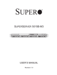
•
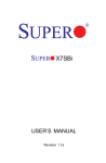
Serverboard Battery: CAUTION - There is a danger of explosion if the onboard
battery is installed upside down, which will reverse its polarites (see Figure
4-1). This battery must be replaced only with the same or an equivalent type
recommended by the manufacturer. Dispose of used batteries according to the
manufacturer's instructions.
•
CD-ROM Laser: CAUTION - this server may have come equipped with a CDROM drive. To prevent direct exposure to the laser beam and hazardous radiation exposure, do not open the enclosure or use the unit in any unconventional
way.
•
4-2
Mainboard replaceable soldered-in fuses: Self-resetting PTC (Positive Temperature Coefficient) fuses on the mainboard must be replaced by trained service
technicians only. The new fuse must be the same or equivalent as the one
replaced. Contact technical support for details and support.
General Safety Precautions
!
Follow these rules to ensure general safety:
•
•
•
•
•
Keep the area around the 5015B-MT clean and free of clutter.
The 5015B-MT weighs approximately 38 lbs (~17.3 kg) when fully loaded.
When lifting the system, two people at either end should lift slowly with their
feet spread out to distribute the weight. Always keep your back straight and lift
with your legs.
Place the chassis top cover and any system components that have been removed away from the system or on a table so that they won't accidentally be
stepped on.
While working on the system, do not wear loose clothing such as neckties and
unbuttoned shirt sleeves, which can come into contact with electrical circuits or
be pulled into a cooling fan.
Remove any jewelry or metal objects from your body, which are excellent metal
conductors that can create short circuits and harm you if they come into contact
with printed circuit boards or areas where power is present.
4-2
Chapter 4: System Safety
•
After accessing the inside of the system, close the system back up and secure
it to the rack unit with the retention screws after ensuring that all connections
have been made.
4-3
ESD Precautions
!
Electrostatic discharge (ESD) is generated by two objects with different electrical
charges coming into contact with each other. An electrical discharge is created to
neutralize this difference, which can damage electronic components and printed
circuit boards. The following measures are generally sufficient to neutralize this
difference before contact is made to protect your equipment from ESD:
•
•
•
•
•
•
•
•
Use a grounded wrist strap designed to prevent static discharge.
Keep all components and printed circuit boards (PCBs) in their antistatic bags
until ready for use.
Touch a grounded metal object before removing the board from the antistatic
bag.
Do not let components or PCBs come into contact with your clothing, which may
retain a charge even if you are wearing a wrist strap.
Handle a board by its edges only; do not touch its components, peripheral chips,
memory modules or contacts.
When handling chips or modules, avoid touching their pins.
Put the serverboard and peripherals back into their antistatic bags when not
in use.
For grounding purposes, make sure your computer chassis provides excellent
conductivity between the power supply, the case, the mounting fasteners and
the serverboard.
4-3
SUPERSERVER 5015B-MT User's Manual
4-4
Operating Precautions
!
Care must be taken to assure that the chassis cover is in place when the 5015B-MT
is operating to assure proper cooling. Out of warranty damage to the system can
occur if this practice is not strictly followed.
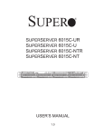
Figure 4-1. Installing the Onboard Battery
LITHIUM BATTERY
LITHIUM BATTERY
OR
BATTERY HOLDER
BATTERY HOLDER
4-4
Chapter 5: Advanced Serverboard Setup
Chapter 5
Advanced Serverboard Setup
This chapter covers the steps required to install the X7SBi serverboard into the chassis, connect the data and power cables and install add-on cards. All serverboard
jumpers and connections are also described. A layout and quick reference chart
are included in this chapter for your reference. Remember to completely close the
chassis when you have finished working with the serverboard to better cool and
protect the system.
5-1
Handling the Serverboard
Electrostatic discharge (ESD) can damage electronic components. To prevent damage to any printed circuit boards (PCBs), it is important to handle them very carefully
(see previous chapter). To prevent the serverboard from bending, keep one hand
under the center of the board to support it when handling. The following measures
are generally sufficient to protect your equipment from electric static discharge.
Precautions
•
•
•
•
•
•
Use a grounded wrist strap designed to prevent Electrostatic Discharge
(ESD).
Touch a grounded metal object before removing any board from its antistatic
bag.
Handle a board by its edges only; do not touch its components, peripheral chips,
memory modules or gold contacts.
When handling chips or modules, avoid touching their pins.
Put the serverboard, add-on cards and peripherals back into their antistatic
bags when not in use.
For grounding purposes, make sure your computer chassis provides excellent
conductivity between the power supply, the case, the mounting fasteners and
the serverboard.
5-1
SUPERSERVER 5015B-MT User's Manual
Unpacking
The serverboard is shipped in antistatic packaging to avoid electrical static discharge. When unpacking the board, make sure the person handling it is static
protected.
5-2
Serverboard Installation
This section explains the first step of physically mounting the X7SBi into the
SC813MTQ-300C chassis. Following the steps in the order given will eliminate
the most common problems encountered in such an installation. To remove the
serverboard, follow the procedure in reverse order.
Installing to the Chassis
1. Access the inside of the system by removing the screws from the back lip of
the top cover of the chassis, then pull the cover off.
2. The X7SBi requires a chassis big enough to support a 12" x 9.6" serverboard,
such as Supermicro's SC813MTQ-300C.
3. Make sure that the I/O ports on the serverboard align properly with their
respective holes in the I/O shield at the back of the chassis.
4. Carefully mount the serverboard to the serverboard tray by aligning the board
holes with the raised metal standoffs that are visible in the chassis.
5. Insert screws into all the mounting holes on your serverboard that line up
with the standoffs and tighten until snug (if you screw them in too tight, you
might strip the threads). Metal screws provide an electrical contact to the
serverboard ground to provide a continuous ground for the system.
6. Finish by replacing the top cover of the chassis.
5-2
Chapter 5: Advanced Serverboard Setup
5-3
Connecting Cables
Now that the serverboard is installed, the next step is to connect the cables to the
board. These include the data cables for the peripherals and control panel and the
power cables.
Connecting Data Cables
The cables used to transfer data from the peripheral devices have been carefully
routed to prevent them from blocking the flow of cooling air that moves through
the system from front to back. If you need to disconnect any of these cables, you
should take care to keep them routed as they were originally after reconnecting
them (make sure the red wires connect to the pin 1 locations). The following data
cables (with their locations noted) should be connected. (See the layout on page
5-11 for connector locations.)
•
Control Panel cable (JF1)
•
DVD-ROM drive cable (IDE)
•
COM Port cable (COM2)
•
Front USB port cable (USB6/7)
•
SATA drive data cables (SATA0 ~ SATA3)
Important! Make sure the the cables do not come into contact with the fans.
Connecting Power Cables
The X7SBi has a 24-pin primary power supply connector (JPW1) for connection
to the ATX power supply. In addition, there is an 8-pin processor power connector
(JPW2) that must be connected to your power supply. See Section 5-9 for power
connector pin definitions.
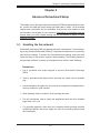
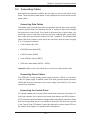
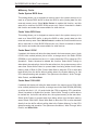
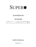
Connecting the Control Panel
JF1 contains header pins for various front control panel connectors. See Figure 5-1
for the pin locations of the various front control panel buttons and LED indicators.
All JF1 wires have been bundled into a single cable to simplify this connection. Make
sure the red wire plugs into pin 1 as marked on the board. The other end connects
to the Control Panel PCB board, located just behind the system status LEDs on
the chassis. See Chapter 5 for details and pin descriptions.
5-3
SUPERSERVER 5015B-MT User's Manual
Figure 5-1. Control Panel Header Pins
20
Ground
NMI
x (Key)
x (Key)
Power On LED
Vcc
HDD LED
Vcc
NIC1 LED
Vcc
NIC2 LED
Vcc
OH/Fan Fail LED
Vcc
Power Fail LED
Vcc
Ground
Reset (Button)
Ground
Power (Button)
2
5-4
19
1
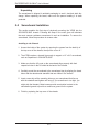
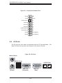
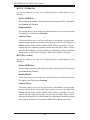
I/O Ports
The I/O ports are color coded in conformance with the PC 99 specification. See
Figure 5-2 below for the colors and locations of the various I/O ports.
Figure 5-2. I/O Ports
Mouse (Green)
USB0/1 Ports
LAN1/2 Ports
Keyboard
(Purple)
COM1 Port
(Turquoise)
VGA Port
(Blue)
5-4
Chapter 5: Advanced Serverboard Setup
5-5
Installing the Processors and Heat Sinks
Avoid placing direct pressure to the top of the processor package. Always
!
remove the power cord first before adding, removing or changing any
hardware components.
Notes: Always connect the power cord last and remove it before adding, removing or changing any components. Make sure to install the processor into the CPU
socket before you install the CPU heat sink.
Intel's boxed Xeon CPU package contains the CPU fan and heat sink assembly. If
you buy the CPUs separately, use only Intel-certified heat sinks and fans.
Inspect the Xeon 3200/3000 CPU socket and make sure that the CPU plastic cap
is in place and none of the socket pins are bent. Otherwise, contact the retailer
immediately.
All graphics shown in this manual are for reference only. The components that
came with your serverboard may or may not look exactly the same as the pictures
shown in this manual.
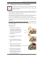
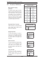
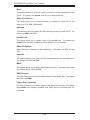
Installing the CPU
1. A black PnP cap is attached to
the load plate to protect the CPU
socket. Press the load lever down
and away from the retention clasp
to release the load plate from its
locked position.
Load lever
PnP cap
2. Gently lift the load lever to release
the load plate.
3. Use your thumb and your index
finger to hold the CPU at opposite
sides.
4. Align pin1 of the CPU (the corner
marked with a triangle) with the
notched corner of the CPU socket.
Load plate released
5. Find the corner of the CPU that
has a semi-circle cutout below a
gold dot (CPU key). This corner
should be aligned with the cutout
on the socket (socket key).
5-5
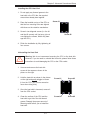
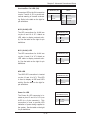
SUPERSERVER 5015B-MT User's Manual
Gold dot
1. Once aligned, carefully lower
the CPU straight down into the
Socket key
socket. Do not drop the CPU on
the socket, do not move the CPU
horizontally or vertically and do not
CPU key
rub the CPU against any surface
or any of the contacts, which may
Notched corner
damage the CPU and/or contacts.
2. With the CPU in the socket, inspect the four corners of the CPU
CPU pin 1
to make sure that it is properly
installed.
3. Use your thumb to gently push the
load lever down until it snaps into
the retention clasp.
Load lever
4. If the CPU is properly installed
into the socket, the PnP cap will
be automatically released from the
load plate when the lever locks.
Remove the cap. Repeat steps to
install a second CPU if desired.
CPU installed in socket
Warning! Keep the plastic PnP cap.
The serverboard must be shipped with
the PnP cap properly installed to protect
the CPU socket. Shipment without the
PnP cap released
from load plate
!
Warning! Make sure you lift the lever completely when installing the CPU;
otherwise, damage to the socket or CPU may occur.
5-6
Chapter 5: Advanced Serverboard Setup
Installing the CPU Heat Sink
1. Do not apply any thermal grease to the
heat sink or the CPU die; the required
amount has already been applied.
2. Place the heatsink on top of the CPU so
Screw #1
that the four mounting holes are aligned
with those on the retention mechanism.
3. Screw in two diagonal screws (i.e. the #1
and the #2 screws) until just snug (do not
Screw #2
over-tighten the screws, which may damage the CPU.)
4. Finish the installation by fully tightening all
four screws.
Uninstalling the Heat Sink
!
Warning: We do not recommend removing the CPU or the heat sink.
However, if you do need to uninstall the heat sink, please follow these
instructions to avoid damaging the CPU or the CPU socket.
1. Unscrew and remove the heat sink
screws in the sequence shown in the
picture on the right.
2. Hold the heat sink as shown in the picture
on the right and gently wriggle to loosen
it from the CPU. (Do not use excessive
force when doing this!)
Screw #1
Screw #3
Screw #4
Screw #2
3. Once the heat sink is loosened, remove it
from the CPU socket.
4. Clean the surface of the CPU and the
heat sink to get rid of the old thermal
grease. Reapply the proper amount of
thermal grease before you re-install the
heat sink.
5-7
SUPERSERVER 5015B-MT User's Manual
5-6
Installing Memory
CAUTION! Exercise extreme care when installing or removing DIMM
!
modules to prevent any possible damage.
Memory Support
The X7SBi supports dual or single channel, ECC/Non-ECC unbuffered DDR2800/667 SDRAM. Both interleaved and non-interleaved memory are supported,
so you may populate any number of DIMM slots. (Populating DIMM#1A/DIMM#2A
and/or DIMM#1B/DIMM#2B with memory modules of the same size and type will
result in two-way interleaved memory, which is faster than single channel, noninterleaved memory.) Note that when ECC memory is used, it may take 25-40
seconds for the VGA to display.)
Installing Memory Modules
1. Insert each DDR2 memory module vertically into its slot, starting with DIMM
#1A. Pay attention to the notch along the bottom of the module to prevent
inserting the module incorrectly.
2. Gently press down on the DIMM module until it snaps into place in the slot.
Repeat for all modules. (See support information below.)
3. To enhance memory performance, install pairs of memory modules of the
same type and of the same, beginning with DIMM #1A and DIMM #2A, then
DIMM #1B and DIMM #2B.
Notes
Due to a chipset limitation, 8GB of memory can only be supported by the following
operating systems:
•
•
32-Bit: Windows 2000 Advanced Server, Windows Server 2003 Enterprise Edition;
64-Bit: Windows Server 2003 Standard x64 Edition, Windows XP Professional
x64 Edition, Windows Server 2003 Enterprise x64 Edition
Some old-versions of DDR2-667 may not match Intel's On-Die Temperature requirement and will automatically be downgraded to run at 533 MHz. If this occurs, contact
your memory vendor to check the ODT value.
Due to memory allocation to system devices, memory remaining available for
operational use will be reduced when 4 GB of RAM is used. The reduction in
memory availability is disproportional. (Refer to the Memory Availability Table
below for details.)
5-8
Chapter 5: Advanced Serverboard Setup
Possible System Memory Allocation & Availability
System Device
Size
Physical Memory Remaining
(4 GB Total System Memory)
Firmware Hub flash memory (System
BIOS)
1 MB
3.99
Local APIC
4 KB
3.99
Area Reserved for the chipset
2 MB
3.99
I/O APIC (4 Kbytes)
4 KB
3.99
PCI Enumeration Area 1
256 MB
3.76
PCI Express (256 MB)
256 MB
3.51
PCI Enumeration Area 2 (if needed)
-Aligned on 256-MB boundary-
512 MB
3.01
VGA Memory
16 MB
2.85
TSEG
1 MB
2.84
Memory available to System BIOS &
OS applications
2.84
Figure 5-3. DIMM Installation
To Install: Insert module vertically and press
down until it snaps into
place. Pay attention to
the bottom notches.
DDR2
5-7
To Remove: Use your
thumbs to gently push
each release tab outward to free the DIMM
from the slot.
Adding PCI Expansion Cards
The SC813MTQ-300C chassis can accommodate one full-size PCI-Express, PCI-X
or PCI expansion card with the use of a riser card.
Installing an Add-on Card
1. After powering down the system, remove the PCI slot shield.
2. Fully seat the riser card into the slot, pushing down with your thumbs evenly
on both sides of the card. Seat the expansion card into the riser card.
3. Finish by using a screw to secure the top of the card shield to the chassis.
The PCI slot shield protects the serverboard and its components from EMI
and aid in proper ventilation, so make sure it is always in place.
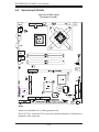
5-9
SUPERSERVER 5015B-MT User's Manual
5-8
Serverboard Details
200
X7SBi
Figure 5-4. X7SBi Layout
(not drawn to scale)
Notes
Jumpers not indicated are for testing purposes only.
Slot 6 PCI-Exp. x8 and the PCI-X slots are specially designed for Supermicro's
proprietary riser cards only.
5-10
Chapter 5: Advanced Serverboard Setup
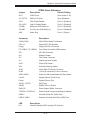
X7SBi Quick Reference
Jumper
Description
Default Setting
JBT1
CMOS Clear
(See Section 5-10)
JI2C1/JI2C2
SMB to PCI Slots
Open (Disabled)
JPG1
VGA Enable/Disable
Pins 1-2 (Enabled)
JPL1/JPL2
LAN1/2 Enable/Disable
Pins 1-2 (Enabled)
JPUSB1
Backpanel USB Wake-Up
Pins 1-2 (Enabled)
JPUSB2
Front Access USB Wake-Up
Pins 2-3 (Disabled)
JWD
Watch Dog
Pins 1-2 (Reset)
Connector
Description
COM1/COM2
COM1/COM2 Serial Port/Header
FAN 1-6
Chassis/CPU Fan Headers
Floppy
Floppy Disk Drive Connector
F/P USB6/7, F/P USB8/9
Front Panel Accessible USB Headers
IDE
IDE HDD Connector
JD1
Speaker Header
JF1
Front Panel Connector
JL1
Chassis Intrusion Header
JLED
Power LED Header
JOH
Overheat Warning Header
JPW1
24-pin Main ATX Power Connector
JPW2
+12V 8-pin Secondary Power Connector
JWOL/JWOR
Wake-On-LAN Header/Wake-On-Ring Header
LAN1/2
Gigabit Ethernet (RJ45) Ports
Printer
Parallel (Printer) Port
SATA0 ~ SATA5
SATA Ports
SIMSO
SIMSO IPMI 2.0 Socket
SMB_PS
Power Supply SMBus Connector
T-SGPIO-1/T-SGPIO-2
Serial General Purpose Input/Output Headers
USB0/1
Universal Serial Bus (USB) Ports
USB10, USB11
Onboard Universal Serial Bus (USB) Ports
LED
Description
LE1
Onboard Standby PWR warning LED Indicator
5-11
SUPERSERVER 5015B-MT User's Manual
5-9
Connector Definitions
ATX Power 24-pin Connector
Pin Definitions (JPW1)
Pin#
Definition
Main ATX Power Supply
Connector
13
+3.3V
1
+3.3V
14
-12V
2
+3.3V
The primary power supply connector
15
COM
3
COM
(JPW1) meets the SSI (Superset ATX)
24-pin specification. Refer to the table
16
PS_ON
4
+5V
17
COM
5
COM
on the right for the pin definitions of
18
COM
6
+5V
the ATX 24-pin power connector. You
19
COM
7
COM
20
Res (NC)
8
PWR_OK
21
+5V
9
5VSB
22
+5V
10
+12V
23
+5V
11
+12V
24
COM
12
+3.3V
must also connect the 8-pin (JPW2/
JPW3) processor power connectors to
your power supply (see below).
Secondary Power Connector
Pin #
Definition
+12V 4-pin Power
Pin Definitions (JPW2)
JPW2 must also be connected to the
power supply. See the table on the
right for pin definitions.
Pins
Definition
1-4
Ground
5-8
+12V
Required Connection
PW_ON Connector
The PW_ON connector is on pins 1
and 2 of JF1. This header should be
connected to the chassis power button. See the table on the right for pin
definitions.
Power Button
Pin Definitions (JF1)
Pin#
Definition
1
PW_ON
2
Ground
Reset Connector
The reset connector is located on pins
3 and 4 of JF1 and attaches to the
reset switch on the computer chassis. See the table on the right for pin
definitions.
Power Fail LED
The Power Fail LED connection is
located on pins 5 and 6 of JF1. Refer to the table on the right for pin
definitions.
5-12
Reset Button
Pin Definitions (JF1)
Pin#
Definition
3
Reset
4
Ground
PWR Fail LED
Pin Definitions (JF1)
Pin#
Definition
5
Vcc
6
Ground
Chapter 5: Advanced Serverboard Setup
Overheat/Fan Fail LED (OH)
Connect an LED to the OH connection
on pins 7 and 8 of JF1 to provide advanced warning of chassis overheating. Refer to the table on the right for
OH/Fan Fail LED
Pin Definitions (JF1)
OH/Fan Fail Indicator
Status
Pin#
Definition
State
7
Vcc
Off
Normal
8
Ground
On
Overheat
Flashing
Fan Fail
pin definitions.
Definition
NIC2 (JLAN2) LED
The LED connections for JLAN2 are
on pins 9 and 10 of JF1. Attach an
LED cable to display network activity. See the table on the right for pin
definitions.
NIC2 LED
Pin Definitions (JF1)
Pin#
Definition
9
Vcc
10
Ground
NIC1 (JLAN1) LED
The LED connections for JLAN1 are
on pins 11 and 12 of JF1. Attach an
LED cable to display network activity. See the table on the right for pin
definitions.
NIC1 LED
Pin Definitions (JF1)
Pin#
Definition
11
Vcc
12
Ground
HDD LED
The HDD LED connection is located
on pins 13 and 14 of JF1. This LED
is used to display all IDE and SATA
activity. See the table on the right for
pin definitions.
Power On LED
The Power On LED connector is located on pins 15 and 16 of JF1 (use
JLED for a 3-pin connector). This
connection is used to provide LED
indication of power being supplied to
the system. See the table on the right
for pin definitions.
5-13
HDD LED
Pin Definitions (JF1)
Pin#
Definition
13
Vcc
14
HD Active
Power LED
Pin Definitions (JF1)
Pin#
Definition
15
5V Stby
16
Control
SUPERSERVER 5015B-MT User's Manual
NMI Button
NMI Button
Pin Definitions (JF1)
The non-maskable interrupt button
header is located on pins 19 and 20
Pin#
Definition
of JF1. Refer to the table on the right
for pin definitions.
19
Control
20
Ground
Fan Headers
There are six fan headers on the
serverboard, all of which are 4-pin
fans. However, pins 1-3 of the fan
Fan Header
Pin Definitions
(FAN1-8)
headers are backward compatible
with the traditional 3-pin fans. See
the table on the right for pin definitions. The onboard fan speeds are
controlled by Thermal Management
(via Hardware Monitoring) under the
Advanced Section in the BIOS. The
default is disabled. When using Thermal Management setting, please use
all 3-pin fans or all 4-pin fans.
Pin#
Definition
1
Ground (Black)
2
+12V (Red)
3
Tachometer
4
PWM Control
Note: Fan 6 is the header for
the CPU heat sink fan.
PS/2 Keyboard and
Mouse Port Pin
Definitions (J28)
ATX PS/2 Keyboard and PS/2
Mouse Ports
The ATX PS/2 keyboard and the PS/2
mouse are located beside the USB0/1
ports. The mouse port is above the
keyboard port. See the table on the
right for pin definitions.
Pin#
Definition
1
Data
2
NC
3
Ground
4
VCC
5
Clock
6
NC
Serial Port Pin Definitions
(COM1/COM2)
Serial Ports
Two serial ports are included on the
serverboard. COM1 is a backpanel
port and COM2 is a header located
beside the printer port. See the table
on the right for pin definitions.
5-14
Pin #
Definition
Pin #
Definition
1
DCD
6
DSR
2
RXD
7
RTS
3
TXD
8
CTS
4
DTR
9
RI
5
Ground
10
NC
Chapter 5: Advanced Serverboard Setup
Chassis Intrusion
Chassis Intrusion
Pin Definitions (JL1)
The Chassis Intrusion header is designated JL1. Attach an appropriate
Pin#
Definition
cable from the chassis to inform you
1
Intrusion Input
2
Ground
of a chassis intrusion when the chassis is opened
Wake-On-LAN
Wake-On-LAN
Pin Definitions
(JWOL)
The Wake-On-LAN header is designated JWOL on the serverboard. See
the table on the right for pin definitions. You must also have a LAN card
with a Wake-On-LAN connector and
cable to use this feature.
Pin#
Definition
1
+5V Standby
2
Ground
3
Wake-up
Wake-On-Ring
The Wake-On-Ring header is designated JWOR. This function allows your
computer to receive and be "awakened" by an incoming call when in the
suspend state. See the table on the
right for pin definitions. You must also
have a WOR card and cable to use
this feature.
Wake-On-Ring
Pin Definitions
(JWOR)
Pin#
Definition
1
Ground (Black)
2
Wake-up
External Speaker/Internal
Buzzer
On the JD1 header, pins 1-4 are for an
external speaker and pins 3-4 are for the
internal speaker. If you wish to use an external speaker, connect it to pins 1-4 to. If
you wish to use the onboard speaker, you
should close pins 3-4 with a jumper.
LAN1/2 (Ethernet Ports)
Two Ethernet ports (designated LAN1
and LAN2) are located beside the VGA
port on the I/O backplane. These ports
accept RJ45 type cables.
5-15
Speaker Connector
(JD1)
Pin Setting
Definition
Pins 3-4
Internal Speaker
Pins 1-4
External Speaker
SUPERSERVER 5015B-MT User's Manual
Universal Serial Bus (USB)
Universal Serial Bus
Pin Definitions (USB)
There are two Universal Serial Bus
ports located on the I/O panel and four
USB0/1/10/11
Pin #
Definition
additional USB headers located on
1
+5V
1
+5V
the serverboard. The headers can be
2
PO-
2
PO-
3
PO+
3
PO+
4
Ground
4
Ground
5
N/A
5
Key
used to provide front side USB access
(cables not included). See the table on
the right for pin definitions.
USB6/7/8/9
Pin #
Definition
SGPIO Header
Pin Definitions (T-SGPIO-1/T-SGPIO-2)
SGPIO Headers
The SGPIO (Serial General Purpose
Input/Output) headers are used to
communicate with a system-monitoring chip on the backplane. See the
table on the right for pin definitions.
Pin#
Definition
Pin
Definition
1
NC
2
NC
3
Ground
4
DATA Out
5
Load
6
Ground
7
Clock
8
NC
NC = No Connection
Power SMB Header
Pin Definitions (PW4)
Power SMBUS Header
A Power SMB header is located at
SMBUS_PS. Connect the appropriate cable here to utilize SMB on your
system. See the table on the right for
pin definitions.
Pin#
Definition
1
Clock
2
Data
3
PWR Fail
4
Ground
5
+3.3V
Overheat LED/Fan Fail (JOH1)
The JOH1 header is used to connect
an LED to provide warning of chassis
overheating. This LED will blink to indicate a fan failure. Refer to the table
on right for pin definitions.
OH/Fan Fail LED
States
Overheat LED
Pin Definitions (JOH1)
State
Message
Pin#
Definition
Solid
Overheat
1
5vDC
Blinking
Fan Fail
2
OH Active
5-16
Chapter 5: Advanced Serverboard Setup
5-10 Jumper Settings
Explanation of Jumpers
To modify the operation of the
serverboard, jumpers can be used
to choose between optional settings.
3
2
1
3
2
1
Connector
Pins
Jumpers create shorts between two
pins to change the function of the connector. Pin 1 is identified with a square
Jumper
solder pad on the printed circuit board.
See the serverboard layout pages for
jumper locations.
Setting
Note: On a two-pin jumper, "Closed"
means the jumper is on both pins and
"Open" means the jumper is either on
only one pin or completely removed.
CMOS Clear
JBT1 is used to clear CMOS (which will also clear any passwords). Instead of pins,
this jumper consists of contact pads to prevent accidentally clearing the contents
of CMOS.
To clear CMOS,
1. First power down the system and unplug the power cord(s).
2. With the power disconnected, short the CMOS pads with a metal object such
as a small screwdriver.
3. Remove the screwdriver (or shorting device).
4. Reconnect the power cord(s) and power on the system.
Note: Do not use the PW_ON connector to clear CMOS.
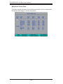
VGA