1
Cisco ONS 15454 SDH Reference Manual
Product and Documentation Release 7.0
Last Updated: October 2008
Corporate Headquarters
Cisco Systems, Inc.
170 West Tasman Drive
San Jose, CA 95134-1706
USA
http://www.cisco.com
Tel: 408 526-4000
800 553-NETS (6387)
Fax: 408 526-4100
Text Part Number: 78-17195-01
THE SPECIFICATIONS AND INFORMATION REGARDING THE PRODUCTS IN THIS MANUAL ARE SUBJECT TO CHANGE WITHOUT NOTICE. ALL
STATEMENTS, INFORMATION, AND RECOMMENDATIONS IN THIS MANUAL ARE BELIEVED TO BE ACCURATE BUT ARE PRESENTED WITHOUT
WARRANTY OF ANY KIND, EXPRESS OR IMPLIED. USERS MUST TAKE FULL RESPONSIBILITY FOR THEIR APPLICATION OF ANY PRODUCTS.
THE SOFTWARE LICENSE AND LIMITED WARRANTY FOR THE ACCOMPANYING PRODUCT ARE SET FORTH IN THE INFORMATION PACKET THAT
SHIPPED WITH THE PRODUCT AND ARE INCORPORATED HEREIN BY THIS REFERENCE. IF YOU ARE UNABLE TO LOCATE THE SOFTWARE LICENSE
OR LIMITED WARRANTY, CONTACT YOUR CISCO REPRESENTATIVE FOR A COPY.
The following information is for FCC compliance of Class A devices: This equipment has been tested and found to comply with the limits for a Class A digital device, pursuant
to part 15 of the FCC rules. These limits are designed to provide reasonable protection against harmful interference when the equipment is operated in a commercial
environment. This equipment generates, uses, and can radiate radio-frequency energy and, if not installed and used in accordance with the instruction manual, may cause
harmful interference to radio communications. Operation of this equipment in a residential area is likely to cause harmful interference, in which case users will be required
to correct the interference at their own expense.
The following information is for FCC compliance of Class B devices: The equipment described in this manual generates and may radiate radio-frequency energy. If it is not
installed in accordance with Cisco’s installation instructions, it may cause interference with radio and television reception. This equipment has been tested and found to
comply with the limits for a Class B digital device in accordance with the specifications in part 15 of the FCC rules. These specifications are designed to provide reasonable
protection against such interference in a residential installation. However, there is no guarantee that interference will not occur in a particular installation.
Modifying the equipment without Cisco’s written authorization may result in the equipment no longer complying with FCC requirements for Class A or Class B digital
devices. In that event, your right to use the equipment may be limited by FCC regulations, and you may be required to correct any interference to radio or television
communications at your own expense.
You can determine whether your equipment is causing interference by turning it off. If the interference stops, it was probably caused by the Cisco equipment or one of its
peripheral devices. If the equipment causes interference to radio or television reception, try to correct the interference by using one or more of the following measures:
• Turn the television or radio antenna until the interference stops.
• Move the equipment to one side or the other of the television or radio.
• Move the equipment farther away from the television or radio.
• Plug the equipment into an outlet that is on a different circuit from the television or radio. (That is, make certain the equipment and the television or radio are on circuits
controlled by different circuit breakers or fuses.)
Modifications to this product not authorized by Cisco Systems, Inc. could void the FCC approval and negate your authority to operate the product.
The Cisco implementation of TCP header compression is an adaptation of a program developed by the University of California, Berkeley (UCB) as part of UCB’s public
domain version of the UNIX operating system. All rights reserved. Copyright © 1981, Regents of the University of California.
NOTWITHSTANDING ANY OTHER WARRANTY HEREIN, ALL DOCUMENT FILES AND SOFTWARE OF THESE SUPPLIERS ARE PROVIDED “AS IS” WITH
ALL FAULTS. CISCO AND THE ABOVE-NAMED SUPPLIERS DISCLAIM ALL WARRANTIES, EXPRESSED OR IMPLIED, INCLUDING, WITHOUT
LIMITATION, THOSE OF MERCHANTABILITY, FITNESS FOR A PARTICULAR PURPOSE AND NONINFRINGEMENT OR ARISING FROM A COURSE OF
DEALING, USAGE, OR TRADE PRACTICE.
IN NO EVENT SHALL CISCO OR ITS SUPPLIERS BE LIABLE FOR ANY INDIRECT, SPECIAL, CONSEQUENTIAL, OR INCIDENTAL DAMAGES, INCLUDING,
WITHOUT LIMITATION, LOST PROFITS OR LOSS OR DAMAGE TO DATA ARISING OUT OF THE USE OR INABILITY TO USE THIS MANUAL, EVEN IF CISCO
OR ITS SUPPLIERS HAVE BEEN ADVISED OF THE POSSIBILITY OF SUCH DAMAGES.
CCDE, CCENT, Cisco Eos, Cisco Lumin, Cisco Nexus, Cisco StadiumVision, Cisco TelePresence, Cisco WebEx, the Cisco logo, DCE, and Welcome to the Human Network
are trademarks; Changing the Way We Work, Live, Play, and Learn and Cisco Store are service marks; and Access Registrar, Aironet, AsyncOS, Bringing the Meeting To
You, Catalyst, CCDA, CCDP, CCIE, CCIP, CCNA, CCNP, CCSP, CCVP, Cisco, the Cisco Certified Internetwork Expert logo, Cisco IOS, Cisco Press, Cisco Systems,
Cisco Systems Capital, the Cisco Systems logo, Cisco Unity, Collaboration Without Limitation, EtherFast, EtherSwitch, Event Center, Fast Step, Follow Me Browsing,
FormShare, GigaDrive, HomeLink, Internet Quotient, IOS, iPhone, iQuick Study, IronPort, the IronPort logo, LightStream, Linksys, MediaTone, MeetingPlace,
MeetingPlace Chime Sound, MGX, Networkers, Networking Academy, Network Registrar, PCNow, PIX, PowerPanels, ProConnect, ScriptShare, SenderBase, SMARTnet,
Spectrum Expert, StackWise, The Fastest Way to Increase Your Internet Quotient, TransPath, WebEx, and the WebEx logo are registered trademarks of Cisco Systems, Inc.
and/or its affiliates in the United States and certain other countries.
All other trademarks mentioned in this document or website are the property of their respective owners. The use of the word partner does not imply a partnership relationship
between Cisco and any other company. (0809R)
Any Internet Protocol (IP) addresses used in this document are not intended to be actual addresses. Any examples, command display output, and figures included in the
document are shown for illustrative purposes only. Any use of actual IP addresses in illustrative content is unintentional and coincidental.
Cisco ONS 15454 SDH Reference Manual, Release 7.0
© 2008 Cisco Systems, Inc. All rights reserved.
CONTENTS
About this Manual
xxxv
Revision History
xxxv
Document Objectives
Audience
xxxvi
xxxvi
Document Organization
xxxvi
Related Documentation
xxxviii
Document Conventions
xxxix
Obtaining Optical Networking Information xlv
Where to Find Safety and Warning Information xlv
Cisco Optical Networking Product Documentation CD-ROM
Obtaining Documentation and Submitting a Service Request
CHAPTER
1
Shelf and FMEC Hardware
1.1 Overview
1.2 Front Door
xlv
xlv
1-1
1-2
1-3
1.3 Front Mount Electrical Connection
1.4 E1-75/120 Conversion Panel
1.5 Coaxial Cable
1-9
1-10
1.6 Twisted-Pair Balanced Cable
1.7 Ethernet Cables
1-7
1-10
1-11
1.8 Cable Routing and Management
1.9 Fiber Management
1-12
1-13
1.10 Fan-Tray Assembly 1-14
1.10.1 Fan Speed 1-15
1.10.2 Air Filter 1-15
1.11 Power and Ground Description
1-16
1.12 Alarm, Timing, LAN, and Craft Pin Connections
1-16
1.13 Cards and Slots 1-16
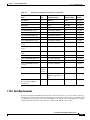
1.13.1 Card Slot Requirements 1-17
1.13.2 Card Replacement 1-19
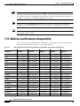
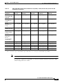
1.14 Software and Hardware Compatibility
1-20
Cisco ONS 15454 SDH Reference Manual, R7.0
October 2008
iii
Contents
CHAPTER
2
Common Control Cards
2-1
2.1 Common Control Card Overview 2-1
2.1.1 Card Summary 2-1
2.1.2 Card Compatibility 2-2
2.1.3 Cross-Connect Card Compatibility
2-3
2.2 TCC2 Card 2-5
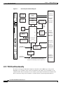
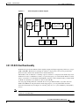
2.2.1 TCC2 Card Functionality 2-6
2.2.2 TCC2 Card-Level Indicators 2-8
2.2.3 Network-Level Indicators 2-8
2.2.4 Power-Level Indicators 2-9
2.3 TCC2P Card 2-9
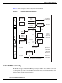
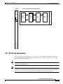
2.3.1 TCC2P Functionality 2-10
2.3.2 TCC2P Card-Level Indicators 2-12
2.3.3 Network-Level Indicators 2-12
2.3.4 Power-Level Indicators 2-13
2.4 XC-VXL-10G Card 2-13
2.4.1 XC-VXL-10G Functionality 2-15
2.4.2 XC-VXL-10G Card-Level Indicators
2-15
2.5 XC-VXL-2.5G Card 2-15
2.5.1 XC-VXL-2.5G Card Functionality 2-17
2.5.2 XC-VXL-2.5G Card-Level Indicators 2-17
2.6 XC-VXC-10G Card 2-17
2.6.1 XC-VXC-10G Functionality 2-18
2.6.2 XC-VXC-10G Card-Level Indicators
2.6.3 XC-VXC-10G Compatibility 2-20
2-20
2.7 AIC-I Card 2-21
2.7.1 AIC-I Card-Level Indicators 2-21
2.7.2 External Alarms and Controls 2-22
2.7.3 Orderwire 2-23
2.7.4 Power Monitoring 2-24
2.7.5 User Data Channel 2-24
2.7.6 Data Communications Channel 2-25
CHAPTER
3
Electrical Cards
3-1
3.1 Electrical Card Overview 3-1
3.1.1 Card Summary 3-2
3.1.2 Card Compatibility 3-4
3.2 E1-N-14 Card
3-4
Cisco ONS 15454 SDH Reference Manual, R7.0
iv
October 2008
Contents
3.2.1 E1-N-14 Card Functionality 3-5
3.2.2 E1-N-14 Card-Level Indicators 3-6
3.2.3 E1-N-14 Port-Level Indicators 3-6
3.3 E1-42 Card 3-6
3.3.1 E1-42 Card Functionality 3-7
3.3.2 E1-42 Card-Level Indicators 3-8
3.3.3 E1-42 Port-Level Indicators 3-8
3.4 E3-12 Card 3-8
3.4.1 E3-12 Card Functionality 3-9
3.4.2 E3-12 Card-Level Indicators 3-10
3.4.3 E3-12 Port-Level Indicators 3-10
3.5 DS3i-N-12 Card 3-10
3.5.1 DS3i-N-12 Card Functionality 3-11
3.5.2 DS3i-N-12 Card-Level Indicators 3-12
3.5.3 DS3i-N-12 Port-Level Indicators 3-12
3.6 STM1E-12 Card 3-12
3.6.1 STM 1E-12 Card Functionality 3-13
3.6.2 STM1E-12 Card-Level Indicators 3-14
3.6.3 STM1E-12 Port-Level Indicators 3-14
3.7 FILLER Card
3-14
3.8 FMEC-E1 Card
3-15
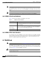
3.9 FMEC-DS1/E1 Card
3-16
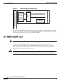
3.10 FMEC E1-120NP Card
3-18
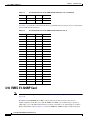
3.11 FMEC E1-120PROA Card
3-21
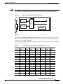
3.12 FMEC E1-120PROB Card
3-23
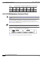
3.13 E1-75/120 Impedance Conversion Panel
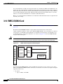
3.14 FMEC-E3/DS3 Card
3-28
3.15 FMEC STM1E 1:1 Card
3.16 BLANK-FMEC Faceplate
3.17 MIC-A/P FMEC
3.18 MIC-C/T/P FMEC
CHAPTER
4
Optical Cards
3-26
3-29
3-29
3-30
3-33
4-1
4.1 Optical Card Overview 4-1
4.1.1 Card Summary 4-2
4.1.2 Card Compatibility 4-3
4.2 OC3 IR 4/STM1 SH 1310 Card
4-5
Cisco ONS 15454 SDH Reference Manual, R7.0
October 2008
v
Contents
4.2.1 OC3 IR 4/STM1 SH 1310 Functionality 4-6
4.2.2 OC3 IR 4/STM1 SH 1310 Card-Level Indicators 4-6
4.2.3 OC3 IR 4/STM1 SH 1310 Port-Level Indicators 4-6
4.3 OC3 IR/STM1 SH 1310-8 Card 4-7
4.3.1 OC3 IR/STM1 SH 1310-8 Card-Level Indicators 4-8
4.3.2 OC3 IR/STM1 SH 1310-8 Port-Level Indicators 4-8
4.4 OC12 IR/STM4 SH 1310 Card 4-8
4.4.1 OC12 IR/STM4 SH 1310 Card-Level Indicators 4-10
4.4.2 OC12 IR/STM4 SH 1310 Port-Level Indicators 4-10
4.5 OC12 LR/STM4 LH 1310 Card 4-10
4.5.1 OC12 LR/STM4 LH 1310 Card-Level Indicators 4-12
4.5.2 OC12 LR/STM4 LH 1310 Port-Level Indicators 4-12
4.6 OC12 LR/STM4 LH 1550 Card 4-12
4.6.1 OC12 LR/STM4 LH 1550 Card Functionality 4-13
4.6.2 OC12 LR/STM4 LH 1550 Card-Level Indicators 4-14
4.6.3 OC12 LR/STM4 LH 1550 Port-Level Indicators 4-14
4.7 OC12 IR/STM4 SH 1310-4 Card 4-14
4.7.1 OC12 IR/STM4 SH 1310-4 Card Functionality 4-15
4.7.2 OC12 IR/STM4 SH 1310-4 Card-Level Indicators 4-16
4.7.3 OC12 IR/STM4 SH 1310-4 Port-Level Indicators 4-16
4.8 OC48 IR/STM16 SH AS 1310 Card 4-16
4.8.1 OC48 IR/STM16 SH AS 1310 Card Functionality 4-17
4.8.2 OC48 IR/STM16 SH AS 1310 Card-Level Indicators 4-18
4.8.3 OC48 IR/STM16 SH AS 1310 Port-Level Indicators 4-18
4.9 OC48 LR/STM16 LH AS 1550 Card 4-18
4.9.1 OC48 LR/STM16 LH AS 1550 Card Functionality 4-19
4.9.2 OC48 LR/STM16 LH AS 1550 Card-Level Indicators 4-20
4.9.3 OC48 LR/STM16 LH AS 1550 Port-Level Indicators 4-20
4.10 OC48 ELR/STM16 EH 100 GHz Cards 4-20
4.10.1 OC48 ELR/STM16 EH 100 GHz Card Functionality 4-21
4.10.2 OC48 ELR/STM16 EH 100 GHz Card-Level Indicators 4-22
4.10.3 OC48 ELR/STM16 EH 100 GHz Port-Level Indicators 4-22
4.11 OC192 SR/STM64 IO 1310 Card 4-23
4.11.1 OC192 SR/STM64 IO 1310 Card Functionality 4-24
4.11.2 OC192 SR/STM64 IO 1310 Card-Level Indicators 4-24
4.11.3 OC192 SR/STM64 IO 1310 Port-Level Indicators 4-24
4.12 OC192 IR/STM64 SH 1550 Card 4-24
4.12.1 OC192 IR/STM64 SH 1550 Card Functionality 4-25
4.12.2 OC192 IR/STM64 SH 1550 Card-Level Indicators 4-26
Cisco ONS 15454 SDH Reference Manual, R7.0
vi
October 2008
Contents
4.12.3 OC192 IR/STM64 SH 1550 Port-Level Indicators
4-26
4.13 OC192 LR/STM64 LH 1550 Card 4-26
4.13.1 OC192 LR/STM64 LH 1550 Card Functionality 4-29
4.13.2 OC192 LR/STM64 LH 1550 Card-Level Indicators 4-30
4.13.3 OC192 LR/STM64 LH 1550 Port-Level Indicators 4-30
4.14 OC192 LR/STM64 LH ITU 15xx.xx Card 4-30
4.14.1 OC192 LR/STM64 LH ITU 15xx.xx Card Functionality 4-32
4.14.2 OC192 LR/STM64 LH ITU 15xx.xx Card-Level Indicators 4-33
4.14.3 OC192 LR/STM64 LH ITU 15xx.xx Port-Level Indicators 4-33
4.15 15454_MRC-12 Multirate Card 4-33
4.15.1 Slot Compatibility by Cross-Connect Card 4-35
4.15.2 Ports and Line Rates 4-35
4.15.3 15454_MRC-12 Card-Level Indicators 4-37
4.15.4 15454_MRC-12 Port-Level Indicators 4-38
4.16 OC192SR1/STM64IO Short Reach and OC192/STM64 Any Reach Cards 4-38
4.16.1 OC192SR1/STM64IO Short Reach and OC192/STM64 Any Reach Card-Level Indicators
4.16.2 OC192SR1/STM64IO Short Reach and OC192/STM64 Any Reach Port-Level Indicators
4-40
4-40
4.17 SFPs and XFPs 4-40
4.17.1 Compatibility by Card 4-40
4.17.2 SFP Description 4-41
4.17.3 XFP Description 4-42
4.17.4 PPM Provisioning 4-43
CHAPTER
5
Ethernet Cards
5-1
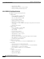
5.1 Ethernet Card Overview 5-1
5.1.1 Cards Summary 5-2
5.1.2 Card Compatibility 5-3
5.2 E100T-G Card 5-3
5.2.1 E100T-G Slot Compatibility 5-5
5.2.2 E100T-G Card-Level Indicators 5-5
5.2.3 E100T-G Port-Level Indicators 5-5
5.2.4 E100T-G Compatibility 5-5
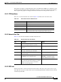
5.3 E1000-2-G Card 5-6
5.3.1 E1000-2-G Card-Level Indicators 5-8
5.3.2 E1000-2-G Port-Level Indicators 5-8
5.3.3 E1000-2-G Compatibility 5-8
5.4 G1000-4 Card 5-9
5.4.1 STS-24c Restriction 5-10
5.4.2 G1000-4 Card-Level Indicators
5-10
Cisco ONS 15454 SDH Reference Manual, R7.0
October 2008
vii
Contents
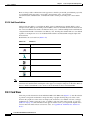
5.4.3 G1000-4 Port-Level Indicators
5.4.4 Slot Compatibility 5-11
5-10
5.5 G1K-4 Card 5-11
5.5.1 G1K-4 Card-Level Indicators 5-12
5.5.2 G1K-4 Port-Level Indicators 5-13
5.5.3 G1K-4 Compatibility 5-13
5.6 ML100T-12 Card 5-13
5.6.1 ML100T-12 Card-Level Indicators 5-15
5.6.2 ML100T-12 Port-Level Indicators 5-15
5.6.3 ML100T-12 Compatibility 5-15
5.7 ML100X-8 Card 5-15
5.7.1 ML100X-8 Card-Level Indicators 5-17
5.7.2 ML100X-8 Port-Level Indicators 5-17
5.7.3 ML100X-8 Compatibility 5-17
5.8 ML1000-2 Card 5-17
5.8.1 ML1000-2 Card-Level Indicators 5-19
5.8.2 ML1000-2 Port-Level Indicators 5-19
5.8.3 ML1000-2 Slot Compatibility 5-19
5.9 CE-100T-8 Card 5-19
5.9.1 CE-100T-8 Card-Level Indicators 5-21
5.9.2 CE-100T-8 Port-Level Indicators 5-21
5.9.3 CE-100T-8 Compatibility 5-22
5.10 CE-1000-4 Card 5-22
5.10.1 CE-1000-4 Card-Level Indicators 5-24
5.10.2 CE-1000-4 Port-Level Indicators 5-25
5.10.3 Cross-Connect and Slot Compatibility 5-25
5.11 Ethernet Card GBICs and SFPs 5-25
5.11.1 Compatibility by Card 5-25
5.11.2 GBIC Description 5-26
5.11.3 DWDM and CWDM GBICs 5-27
5.11.4 SFP Description 5-29
CHAPTER
6
Storage Access Networking Cards
6-1
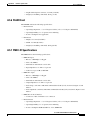
6.1 FC_MR-4 Card Overview 6-1
6.1.1 FC_MR-4 Card-Level Indicators 6-2
6.1.2 FC_MR-4 Port-Level Indicators 6-3
6.1.3 FC_MR-4 Compatibility 6-3
6.2 FC_MR-4 Card Modes 6-3
6.2.1 Line-Rate Card Mode 6-3
Cisco ONS 15454 SDH Reference Manual, R7.0
viii
October 2008
Contents
6.2.2 Enhanced Card Mode 6-4
6.2.2.1 Mapping 6-4
6.2.2.2 SW-LCAS 6-4
6.2.2.3 Distance Extension 6-5
6.2.2.4 Differential Delay Features 6-5
6.2.2.5 Interoperability Features 6-6
6.2.3 Link Integrity 6-6
6.2.4 Link Recovery 6-6
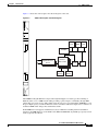
6.3 FC_MR-4 Card Application
6.4 FC_MR-4 Card GBICs
CHAPTER
7
Card Protection
6-6
6-7
7-1
7.1 Electrical Card Protection 7-1
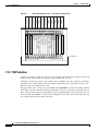
7.1.1 1:1 Protection 7-1
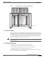
7.1.2 1:N Protection 7-2
7.1.2.1 Revertive Switching 7-3
7.1.2.2 1:N Protection Guidelines
7.2 STM-N Card Protection
7.3 Unprotected Cards
7-4
7-4
7.4 External Switching Commands
CHAPTER
8
7-3
7-5
Cisco Transport Controller Operation
8-1
8.1 CTC Software Delivery Methods 8-1
8.1.1 CTC Software Installed on the TCC2/TCC2P Card 8-1
8.1.2 CTC Software Installed on the PC or UNIX Workstation
8.2 CTC Installation Overview
8-4
8.3 PC and UNIX Workstation Requirements
8.4 ONS 15454 SDH Connection
8-3
8-4
8-6
8.5 CTC Window 8-7
8.5.1 Node View 8-8
8.5.1.1 CTC Card Colors 8-8
8.5.1.2 Card and Port States 8-10
8.5.1.3 Node View Card Shortcuts 8-11
8.5.1.4 Node View Tabs 8-11
8.5.2 Network View 8-12
8.5.2.1 CTC Node Colors 8-13
8.5.2.2 Network View Tabs 8-13
8.5.2.3 DCC Links 8-13
Cisco ONS 15454 SDH Reference Manual, R7.0
October 2008
ix
Contents
8.5.2.4 Link Consolidation 8-14
8.5.3 Card View 8-14
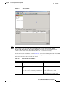
8.5.4 Print or Export CTC Data 8-16
8.6 TCC2/TCC2P Card Reset
8-17
8.7 TCC2/TCC2P Card Database
8.8 Software Revert
CHAPTER
Security
9
8-17
8-17
9-1
9.1 User IDs and Security Levels
9-1
9.2 User Privileges and Policies 9-1
9.2.1 User Privileges by CTC Task 9-2
9.2.2 Security Policies 9-5
9.2.2.1 Superuser Privileges for Provisioning Users 9-6
9.2.2.2 Idle User Timeout 9-6
9.2.2.3 User Password, Login, and Access Policies 9-6
9.2.2.4 Secure Access 9-6
9.3 Audit Trail 9-7
9.3.1 Audit Trail Log Entries 9-7
9.3.2 Audit Trail Capacities 9-8
9.4 RADIUS Security 9-8
9.4.1 RADIUS Authentication
9.4.2 Shared Secrets 9-9
CHAPTER
10
Timing
9-8
10-1
10.1 Timing Parameters
10.2 Network Timing
10-1
10-2
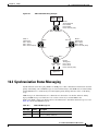
10.3 Synchronization Status Messaging
CHAPTER
11
Circuits and Tunnels
11.1 Overview
10-3
11-1
11-2
11.2 Circuit Properties 11-2
11.2.1 Concatenated VC4 Time Slot Assignments 11-4
11.2.2 Circuit Status 11-6
11.2.3 Circuit States 11-7
11.2.4 Circuit Protection Types 11-8
11.2.5 Circuit Information in the Edit Circuit Window 11-9
11.3 Cross-Connect Card Bandwidth
11.4 DCC Tunnels
11-11
11-12
Cisco ONS 15454 SDH Reference Manual, R7.0
x
October 2008
Contents
11.4.1 Traditional DCC Tunnels
11.4.2 IP-Encapsulated Tunnels
11-12
11-13
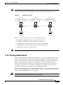
11.5 Multiple Destinations for Unidirectional Circuits
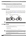
11.6 Monitor Circuits
11-14
11-14
11.7 SNCP Circuits 11-14
11.7.1 Open-Ended SNCP Circuits 11-15
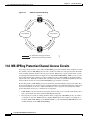
11.7.2 Go-and-Return SNCP Routing 11-15
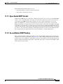
11.8 MS-SPRing Protection Channel Access Circuits
11.9 MS-SPRing VC4 Squelch Table
11.10 Section and Path Trace
11-16
11-17
11-17
11.11 Path Signal Label, C2 Byte
11-18
11.12 Automatic Circuit Routing 11-19
11.12.1 Bandwidth Allocation and Routing 11-19
11.12.2 Secondary Sources and Destinations 11-19
11.13 Manual Circuit Routing
11-20
11.14 Constraint-Based Circuit Routing
11-24
11.15 Virtual Concatenated Circuits 11-25
11.15.1 VCAT Circuit States 11-25
11.15.2 VCAT Member Routing 11-25
11.15.3 Link Capacity Adjustment 11-26
11.15.4 VCAT Circuit Size 11-27
11.16 Bridge and Roll 11-28
11.16.1 Rolls Window 11-29
11.16.2 Roll Status 11-30
11.16.3 Single and Dual Rolls 11-30
11.16.4 Two Circuit Bridge and Roll 11-32
11.16.5 Protected Circuits 11-33
11.17 Merged Circuits
11-33
11.18 Reconfigured Circuits
11.19 Server Trails
CHAPTER
12
11-34
11-34
SDH Topologies and Upgrades
12-1
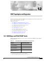
12.1 SDH Rings and TCC2/TCC2P Cards
12-1
12.2 Multiplex Section-Shared Protection Rings 12-2
12.2.1 Two-Fiber MS-SPRings 12-2
12.2.2 Four-Fiber MS-SPRings 12-5
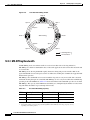
12.2.3 MS-SPRing Bandwidth 12-8
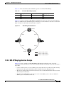
12.2.4 MS-SPRing Application Sample 12-9
Cisco ONS 15454 SDH Reference Manual, R7.0
October 2008
xi
Contents
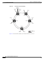
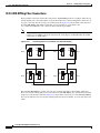
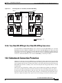
12.2.5 MS-SPRing Fiber Connections 12-12
12.2.6 Two-Fiber MS-SPRing to Four-Fiber MS-SPRing Conversion
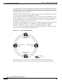
12.3 Subnetwork Connection Protection
12-13
12.4 Dual Ring Interconnect 12-18
12.4.1 MS-SPRing DRI 12-18
12.4.2 SNCP Dual Ring Interconnect 12-21
12.4.3 SNCP/MS-SPRing DRI Handoff Configurations
12.5 Subtending Rings
12-13
12-24
12-25
12.6 Linear ADM Configurations
12-27
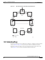
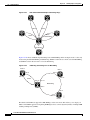
12.7 Extended SNCP Mesh Networks
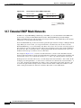
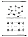
12.8 Four Node Configurations
12-28
12-30
12.9 STM-N Speed Upgrades 12-30
12.9.1 Span Upgrade Wizard 12-31
12.9.2 Manual Span Upgrades 12-31
CHAPTER
13
Management Network Connectivity
13.1 IP Networking Overview
13-1
13-2
13.2 IP Addressing Scenarios 13-2
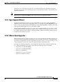
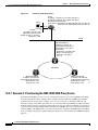
13.2.1 Scenario 1: CTC and ONS 15454 SDH Nodes on Same Subnet 13-3
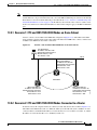
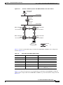
13.2.2 Scenario 2: CTC and ONS 15454 SDH Nodes Connected to a Router 13-3
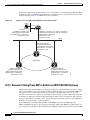
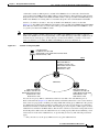
13.2.3 Scenario 3: Using Proxy ARP to Enable an ONS 15454 SDH Gateway 13-4
13.2.4 Scenario 4: Default Gateway on CTC Computer 13-6
13.2.5 Scenario 5: Using Static Routes to Connect to LANs 13-7
13.2.6 Scenario 6: Using OSPF 13-10
13.2.7 Scenario 7: Provisioning the ONS 15454 SDH Proxy Server 13-12
13.2.8 Scenario 8: Dual GNEs on a Subnet 13-18
13.2.9 Scenario 9: IP Addressing with Secure Mode Enabled 13-20
13.3 Provisionable Patchcords
13.4 Routing Table
13-24
13.5 External Firewalls
13.6 Open GNE
13-22
13-26
13-27
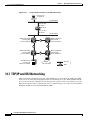
13.7 TCP/IP and OSI Networking 13-30
13.7.1 Point-to-Point Protocol 13-31
13.7.2 Link Access Protocol on the D Channel 13-32
13.7.3 OSI Connectionless Network Service 13-32
13.7.4 OSI Routing 13-35
13.7.4.1 End System-to-Intermediate System Protocol 13-36
13.7.4.2 Intermediate System-to-Intermediate System 13-36
Cisco ONS 15454 SDH Reference Manual, R7.0
xii
October 2008
Contents
13.7.5 TARP 13-37
13.7.5.1 TARP Processing 13-38
13.7.5.2 TARP Loop Detection Buffer 13-39
13.7.5.3 Manual TARP Adjacencies 13-40
13.7.5.4 Manual TID to NSAP Provisioning 13-40
13.7.6 TCP/IP and OSI Mediation 13-40
13.7.7 OSI Virtual Routers 13-41
13.7.8 IP-over-CLNS Tunnels 13-42
13.7.8.1 Provisioning IP-over-CLNS Tunnels 13-43
13.7.8.2 IP-over-CLNS Tunnel Scenario 1: ONS Node to Other Vendor GNE 13-44
13.7.8.3 IP-over-CLNS Tunnel Scenario 2: ONS Node to Router 13-45
13.7.8.4 IP-over-CLNS Tunnel Scenario 3: ONS Node to Router Across an OSI DCN 13-47
13.7.9 OSI/IP Networking Scenarios 13-48
13.7.9.1 OSI/IP Scenario 1: IP OSS, IP DCN, ONS GNE, IP DCC, and ONS ENE 13-49
13.7.9.2 OSI/IP Scenario 2: IP OSS, IP DCN, ONS GNE, OSI DCC, and Other Vendor ENE 13-49
13.7.9.3 OSI/IP Scenario 3: IP OSS, IP DCN, Other Vendor GNE, OSI DCC, and ONS ENE 13-51
13.7.9.4 OSI/IP Scenario 4: Multiple ONS DCC Areas 13-53
13.7.9.5 OSI/IP Scenario 5: GNE Without an OSI DCC Connection 13-54
13.7.9.6 OSI/IP Scenario 6: IP OSS, OSI DCN, ONS GNE, OSI DCC, and Other Vendor ENE 13-55
13.7.9.7 OSI/IP Scenario 7: OSI OSS, OSI DCN, Other Vendor GNE, OSI DCC, and ONS
NEs 13-56
13.7.9.8 OSI/IP Scenario 8: OSI OSS, OSI DCN, ONS GNE, OSI DCC, and Other Vendor
NEs 13-58
13.7.10 Provisioning OSI in CTC 13-60
CHAPTER
14
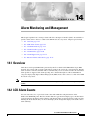
Alarm Monitoring and Management
14.1 Overview
14-1
14-1
14.2 LCD Alarm Counts
14-1
14.3 Alarm Information 14-2
14.3.1 Viewing Alarms With Each Node’s Time Zone 14-4
14.3.2 Controlling Alarm Display 14-4
14.3.3 Filtering Alarms 14-5
14.3.4 Viewing Alarm-Affected Circuits 14-5
14.3.5 Conditions Tab 14-6
14.3.6 Controlling the Conditions Display 14-6
14.3.6.1 Retrieving and Displaying Conditions 14-7
14.3.6.2 Conditions Column Descriptions 14-7
14.3.6.3 Filtering Conditions 14-8
14.3.7 Viewing History 14-8
14.3.7.1 History Column Descriptions 14-9
Cisco ONS 15454 SDH Reference Manual, R7.0
October 2008
xiii
Contents
14.3.7.2 Retrieving and Displaying Alarm and Condition History
14.3.8 Alarm History and Log Buffer Capacities 14-10
14.4 Alarm Severities
14-9
14-10
14.5 Alarm Profiles 14-10
14.5.1 Creating and Modifying Alarm Profiles
14.5.2 Alarm Profile Buttons 14-12
14.5.3 Alarm Profile Editing 14-12
14.5.4 Alarm Severity Options 14-12
14.5.5 Row Display Options 14-13
14.5.6 Applying Alarm Profiles 14-13
14-11
14.6 Alarm Suppression 14-14
14.6.1 Alarms Suppressed for Maintenance 14-14
14.6.2 Alarms Suppressed by User Command 14-15
14.7 External Alarms and Controls 14-15
14.7.1 External Alarm Input 14-15
14.7.2 External Control Output 14-16
CHAPTER
15
Performance Monitoring
15-1
15.1 Threshold Performance Monitoring
15-1
15.2 Intermediate-Path Performance Monitoring
15-3
15.3 Pointer Justification Count Performance Monitoring
15.4 Performance Monitoring Parameter Definitions
15-4
15-4
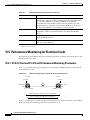
15.5 Performance Monitoring for Electrical Cards 15-14
15.5.1 E1-N-14 Card and E1-42 Card Performance Monitoring Parameters
15.5.2 E3-12 Card Performance Monitoring Parameters 15-16
15.5.3 DS3i-N-12 Card Performance Monitoring Parameters 15-17
15-14
15.6 Performance Monitoring for Ethernet Cards 15-19
15.6.1 E-Series Ethernet Card Performance Monitoring Parameters 15-19
15.6.1.1 E-Series Ethernet Statistics Window 15-19
15.6.1.2 E-Series Ethernet Utilization Window 15-20
15.6.1.3 E-Series Ethernet History Window 15-20
15.6.2 G-Series Ethernet Card Performance Monitoring Parameters 15-21
15.6.2.1 G-Series Ethernet Statistics Window 15-21
15.6.2.2 G-Series Ethernet Utilization Window 15-22
15.6.2.3 G-Series Ethernet History Window 15-23
15.6.3 ML-Series Ethernet Card Performance Monitoring Parameters 15-23
15.6.3.1 ML-Series Ether Ports Parameters 15-23
15.6.3.2 ML-Series POS Ports Parameters 15-24
Cisco ONS 15454 SDH Reference Manual, R7.0
xiv
October 2008
Contents
15.6.4 CE-Series Ethernet Card Performance Monitoring Parameters 15-26
15.6.4.1 CE-Series Ether Ports Statistics Parameters 15-26
15.6.4.2 CE-Series Card Ether Ports Utilization Parameters 15-30
15.6.4.3 CE-Series Card Ether Ports History Parameters 15-30
15.6.4.4 CE-Series POS Ports Statistics Parameters 15-30
15.6.4.5 CE-Series Card POS Ports Utilization Parameters 15-31
15.6.4.6 CE-Series Card Ether Ports History Parameters 15-31
15.7 Performance Monitoring for Optical Cards 15-31
15.7.1 STM-1 Card Performance Monitoring Parameters 15-32
15.7.2 STM-1E Card Performance Monitoring Parameters 15-34
15.7.3 STM-4 Card Performance Monitoring Parameters 15-36
15.7.4 STM-16 and STM-64 Card Performance Monitoring Parameters
15.7.5 MRC-12 Card Performance Monitoring Parameters 15-39
15-37
15.8 Performance Monitoring for the Fiber Channel Card 15-40
15.8.1 FC_MR-4 Card Performance Monitoring Parameters 15-40
15.8.1.1 FC_MR-4 Statistics Window 15-41
15.8.1.2 FC_MR-4 Utilization Window 15-42
15.8.1.3 FC_MR-4 History Window 15-42
CHAPTER
16
SNMP
16-1
16.1 SNMP Overview
16-1
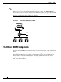
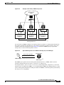
16.2 Basic SNMP Components
16-2
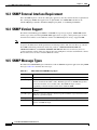
16.3 SNMP External Interface Requirement
16.4 SNMP Version Support
16-4
16.5 SNMP Message Types
16-4
16-4
16.6 SNMP Management Information Bases 16-5
16.6.1 IETF-Standard MIBS for ONS 15454 SDH 16-5
16.6.2 Proprietary ONS 15454 SDH MIBS 16-6
16.6.3 Generic Threshold and Performance Monitoring MIBs
16.7 SNMP Trap Content 16-8
16.7.1 Generic and IETF Traps
16.7.2 Variable Trap Bindings
16.8 SNMP Community Names
16.9 Proxy Over Firewalls
16-7
16-9
16-10
16-16
16-16
16.10 Remote Monitoring 16-16
16.10.1 64-Bit RMON Monitoring over DCC 16-17
16.10.1.1 Row Creation in MediaIndependentTable 16-17
16.10.1.2 Row Creation in cMediaIndependentHistoryControlTable
16-18
Cisco ONS 15454 SDH Reference Manual, R7.0
October 2008
xv
Contents
16.10.2 HC-RMON-MIB Support 16-18
16.10.3 Ethernet Statistics RMON Group 16-18
16.10.3.1 Row Creation in etherStatsTable 16-18
16.10.3.2 Get Requests and GetNext Requests 16-19
16.10.3.3 Row Deletion in etherStatsTable 16-19
16.10.3.4 64-Bit etherStatsHighCapacity Table 16-19
16.10.4 History Control RMON Group 16-19
16.10.4.1 History Control Table 16-19
16.10.4.2 Row Creation in historyControlTable 16-19
16.10.4.3 Get Requests and GetNext Requests 16-20
16.10.4.4 Row Deletion in historyControl Table 16-20
16.10.5 Ethernet History RMON Group 16-20
16.10.6 Alarm RMON Group 16-20
16.10.6.1 Alarm Table 16-20
16.10.6.2 Row Creation in alarmTable 16-21
16.10.6.3 Get Requests and GetNext Requests 16-22
16.10.6.4 Row Deletion in alarmTable 16-22
16.10.7 Event RMON Group 16-22
16.10.7.1 Event Table 16-23
16.10.7.2 Log Table 16-23
APPENDIX
A
Hardware Specifications
A-1
A.1 Shelf Specifications A-1
A.1.1 Bandwidth A-1
A.1.2 Configurations A-1
A.1.3 Cisco Transport Controller A-2
A.1.4 External LAN Interface A-2
A.1.5 Alarm Interface A-2
A.1.6 Database Storage A-2
A.1.7 Timing Interface A-2
A.1.8 System Timing A-3
A.1.9 System Power A-3
A.1.10 System Environmental Specifications
A.1.11 Dimensions A-3
A.2 SFP and XFP Specifications
A-3
A-3
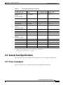
A.3 General Card Specifications A-5
A.3.1 Power Consumption A-5
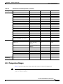
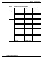
A.3.2 Temperature Ranges A-7
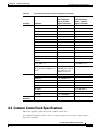
A.4 Common Control Card Specifications
A-9
Cisco ONS 15454 SDH Reference Manual, R7.0
xvi
October 2008
Contents
A.4.1
A.4.2
A.4.3
A.4.4
A.4.5
A.4.6
TCC2 Card Specifications A-10
TCC2P Card Specifications A-10
XC-VXL-10G Card Specifications A-11
XC-VXL-2.5G Card Specifications A-12
XC-XVC-10G Card Specifications A-12
AIC-I Specifications A-12
A.5 Electrical Card and FMEC Specifications A-14
A.5.1 E1-N-14 Card Specifications A-14
A.5.2 E1-42 Card Specifications A-15
A.5.3 E3-12 Card Specifications A-16
A.5.4 DS3i-N-12 Card Specifications A-17
A.5.5 STM1E-12 Card Specifications A-18
A.5.6 FILLER Card A-19
A.5.7 FMEC-E1 Specifications A-19
A.5.8 FMEC-DS1/E1 Specifications A-20
A.5.9 FMEC E1-120NP Specifications A-21
A.5.10 FMEC E1-120PROA Specifications A-21
A.5.11 FMEC E1-120PROB Specifications A-22
A.5.12 E1-75/120 Impedance Conversion Panel Specifications
A.5.13 FMEC-E3/DS3 Specifications A-24
A.5.14 FMEC STM1E 1:1 Specifications A-25
A.5.15 BLANK-FMEC Specifications A-26
A.5.16 MIC-A/P Specifications A-26
A.5.17 MIC-C/T/P Specifications A-27
A-23
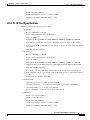
A.6 Optical Card Specifications A-28
A.6.1 OC3 IR 4/STM1 SH 1310 Card Specifications A-28
A.6.2 OC3 IR/STM1 SH 1310-8 Card Specifications A-29
A.6.3 OC12 IR/STM4 SH 1310 Card Specifications A-30
A.6.4 OC12 LR/STM4 LH 1310 Card Specifications A-31
A.6.5 OC12 LR/STM4 LH 1550 Card Specifications A-32
A.6.6 OC12 IR/STM4 SH 1310-4 Card Specifications A-33
A.6.7 OC48 IR/STM16 SH AS 1310 Card Specifications A-34
A.6.8 OC48 LR/STM16 LH AS 1550 Card Specifications A-34
A.6.9 OC48 ELR/STM16 EH 100 GHz Card Specifications A-35
A.6.10 OC192 SR/STM64 IO 1310 Card Specifications A-37
A.6.11 OC192 IR/STM64 SH 1550 Card Specifications A-38
A.6.12 OC192 LR/STM64 LH 1550 Card Specifications A-39
A.6.13 OC192 LR/STM64 LH ITU 15xx.xx Card Specifications A-40
A.6.14 15454_MRC-12 Card Specifications A-41
A.6.15 OC192SR1/STM64IO Short Reach Card Specifications A-42
Cisco ONS 15454 SDH Reference Manual, R7.0
October 2008
xvii
Contents
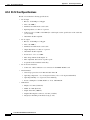
A.6.16 OC192/STM64 Any Reach Card Specifications
A-43
A.7 Ethernet Card Specifications A-44
A.7.1 E100T-G Card Specifications A-44
A.7.2 E1000-2-G Card Specifications A-45
A.7.3 CE-1000-4 Card Specifications A-45
A.7.4 CE-100T-8 Card Specifications A-45
A.7.5 G1K-4 Card Specifications A-46
A.7.6 ML100T-12 Card Specifications A-46
A.7.7 ML1000-2 Card Specifications A-47
A.7.8 ML100X-8 Card Specifications A-47
A.8 Storage Access Networking Card Specifications
A.8.1 FC_MR-4 Card Specifications A-48
APPENDIX
B
Administrative and Service States
B.1 Service States
A-48
B-1
B-1
B.2 Administrative States
B-2
B.3 Service State Transitions B-3
B.3.1 Card Service State Transitions B-3
B.3.2 Port and Cross-Connect Service State Transitions
APPENDIX
C
Network Element Defaults
B-6
C-1
C.1 Network Element Defaults Description
C-1
C.2 Card Default Settings C-2
C.2.1 Configuration Defaults C-2
C.2.2 Threshold Defaults C-3
C.2.3 Defaults by Card C-4
C.2.3.1 E1-N-14 Card Default Settings C-4
C.2.3.2 E1-42 Card Default Settings C-6
C.2.3.3 E3-12 Card Default Settings C-7
C.2.3.4 DS3i-N-12 Card Default Settings C-9
C.2.3.5 STM1E-12 Card Default Settings C-12
C.2.3.6 Ethernet Card Default Settings C-14
C.2.3.7 STM-1 Card Default Settings C-15
C.2.3.8 STM1-8 Card Default Settings C-17
C.2.3.9 STM-4 Card Default Settings C-21
C.2.3.10 STM4-4 Card Default Settings C-23
C.2.3.11 STM-16 Card Default Settings C-25
C.2.3.12 STM-64 Card Default Settings C-28
C.2.3.13 STM64-XFP Default Settings C-31
Cisco ONS 15454 SDH Reference Manual, R7.0
xviii
October 2008
Contents
C.2.3.14 MRC-12 Card Default Settings C-35
C.2.3.15 FC_MR-4 Card Default Settings C-45
C.3 Node Default Settings C-46
C.3.1 Time Zones C-55
C.4 CTC Default Settings
C-58
INDEX
Cisco ONS 15454 SDH Reference Manual, R7.0
October 2008
xix
Contents
Cisco ONS 15454 SDH Reference Manual, R7.0
xx
October 2008
F I G U R E S
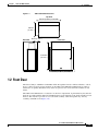
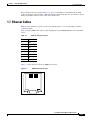
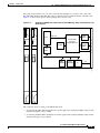
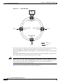
Figure 1-1
ONS 15454 SDH Dimensions
Figure 1-2
The ONS 15454 SDH Front Door
Figure 1-3
Removing the ONS 15454 SDH Front Door
Figure 1-4
Front-Door Erasable Label
Figure 1-5
Laser Warning on the Front-Door Label
Figure 1-6
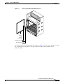
Mounting the E1-75/120 Conversion Panel in a Rack
Figure 1-7
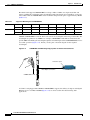
100BaseT Connector Pins
Figure 1-8
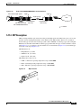
Straight-Through Cable
Figure 1-9
Crossover Cable
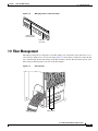
Figure 1-10
Managing Cables on the Front Panel
Figure 1-11
Fiber Capacity
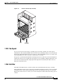
Figure 1-12
Position of the Fan-Tray Assembly
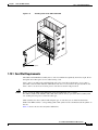
Figure 1-13
Installing Cards in the ONS 15454 SDH
Figure 2-1
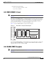
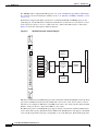
TCC2 Faceplate and Block Diagram
Figure 2-2
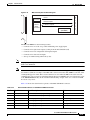
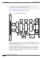
TCC2P Faceplate and Block Diagram
Figure 2-3
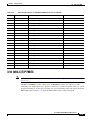
XC-VXL-10G Faceplate and Block Diagram
Figure 2-4
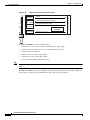
XC-VXL-10G Cross-Connect Matrix
Figure 2-5
XC-VXL-2.5G Faceplate and Block Diagram
Figure 2-6
XC-VXL-2.5G Cross-Connect Matrix
Figure 2-7
XC-VXC-10G Faceplate and Block Diagram
Figure 2-8
XC-VXC-10G Cross-Connect Matrix
2-20
Figure 2-9
AIC-I Faceplate and Block Diagram
2-21
Figure 2-10
RJ-11 Cable Connector
Figure 3-1
E1-N-14 Faceplate and Block Diagram
Figure 3-2
E1-42 Faceplate and Block Diagram
Figure 3-3
E3-12 Card Faceplate and Block Diagram
3-9
Figure 3-4
DS3i-N-12 Faceplate and Block Diagram
3-11
Figure 3-5
STM1E-12 Faceplate and Block Diagram
3-13
Figure 3-6
FILLER Faceplate
Figure 3-7
FMEC-E1 Faceplate and Block Diagram
Figure 3-8
FMEC-DS1/E1 Faceplate and Block Diagram
1-3
1-4
1-5
1-6
1-7
1-10
1-11
1-12
1-12
1-13
1-13
1-15
1-17
2-6
2-10
2-14
2-14
2-16
2-16
2-18
2-24
3-5
3-7
3-15
3-16
3-17
Cisco ONS 15454 SDH Reference Manual, R7.0
October 2008
xxi
Figures
Figure 3-9
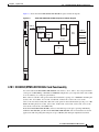
FMEC E1-120NP Faceplate and Block Diagram
Figure 3-10
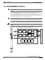
FMEC E1-120PROA Faceplate and Block Diagram
3-21
Figure 3-11
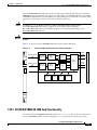
FMEC E1-120PROB Faceplate and Block Diagram
3-24
Figure 3-12
E1-75/120 Impedance Conversion Panel Faceplate
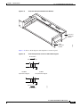
Figure 3-13
E1-75/120 with Optional Rackmount Brackets
Figure 3-14
E1-75/120 Impedance Conversion Panel Block Diagram
Figure 3-15
FMEC-E3/DS3 Faceplate and Block Diagram
Figure 3-16
FMEC STM1E 1:1 Faceplate and Block Diagram
Figure 3-17
BLANK-FMEC Faceplate
Figure 3-18
MIC-A/P Faceplate and Block Diagram
Figure 3-19
MIC-C/T/P Faceplate and Block Diagram
Figure 4-1
OC3 IR 4/STM1 SH 1310 Faceplate and Block Diagram
4-5
Figure 4-2
OC3 IR/STM1 SH 1310-8 Faceplate and Block Diagram
4-7
Figure 4-3
OC12 IR/STM4 SH 1310 Faceplate and Block Diagram
4-9
Figure 4-4
OC12 LR/STM4 LH 1310 Faceplate and Block Diagram
4-11
Figure 4-5
OC12 LR/STM4 LH 1550 Faceplate and Block Diagram
4-13
Figure 4-6
OC12 IR/STM4 SH 1310-4 Faceplate and Block Diagram
Figure 4-7
OC48 IR/STM16 SH AS 1310 Faceplate and Block Diagram
4-17
Figure 4-8
OC48 LR/STM16 LH AS 1550 Faceplate and Block Diagram
4-19
Figure 4-9
OC48 ELR/STM16 EH 100 GHz Faceplate and Block Diagram
Figure 4-10
OC192 SR/STM64 IO 1310 Faceplate and Block Diagram
4-23
Figure 4-11
OC192 IR/STM64 SH 1550 Faceplate and Block Diagram
4-25
Figure 4-12
OC192 LR/STM64 LH 1550 Faceplate and Block Diagram
4-28
Figure 4-13
Enlarged Section of the OC192 LR/STM64 LH 1550 Faceplate
Figure 4-14
OC192 LR/STM64 LH ITU 15xx.xx Faceplate
Figure 4-15
OC192 LR/STM64 LH ITU 15xx.xx Block Diagram
Figure 4-16
15454_MRC-12 Card Faceplate and Block Diagram
Figure 4-17
OC192SR1/STM64IO Short Reach and OC192/STM64 Any Reach Card Faceplates and Block Diagram
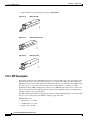
Figure 4-18
Mylar Tab SFP
Figure 4-19
Actuator/Button SFP
Figure 4-20
Bail Clasp SFP
Figure 4-21
Bail Clasp XFP (Unlatched)
Figure 4-22
Bail Clasp XFP (Latched)
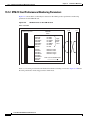
Figure 5-1
E100T-G Faceplate and Block Diagram
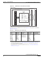
Figure 5-2
E1000-2-G Faceplate and Block Diagram
3-19
3-26
3-27
3-27
3-28
3-29
3-30
3-31
3-34
4-15
4-21
4-29
4-31
4-32
4-34
4-39
4-42
4-42
4-42
4-43
4-43
5-4
5-7
Cisco ONS 15454 SDH Reference Manual, R7.0
xxii
October 2008
Figures
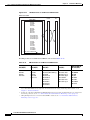
Figure 5-3
G1000-4 Faceplate and Block Diagram
Figure 5-4
G1K-4 Faceplate and Block Diagram
Figure 5-5
ML100T-12 Faceplate and Block Diagram
Figure 5-6
ML100X-8 Faceplate and Block Diagram
5-16
Figure 5-7
ML1000-2 Faceplate and Block Diagram
5-18
Figure 5-8
CE-100T-8 Faceplate and Block Diagram
5-20
Figure 5-9
CE-1000-4 Faceplate and Block Diagram
5-24
Figure 5-10
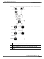
GBICs with Clips (left) and with a Handle (right)
Figure 5-11
CWDM GBIC with Wavelength Appropriate for Fiber-Connected Device
Figure 5-12
G-1K-4 with CWDM/DWDM GBICs in Cable Network
Figure 5-13
Mylar Tab SFP
Figure 5-14
Actuator/Button SFP
Figure 5-15
Bail Clasp SFP
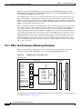
Figure 6-1
FC_MR-4 Faceplate and Block Diagram
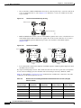
Figure 7-1
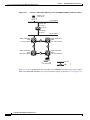
ONS 15454 SDH Cards in a 1:1 Protection Configuration
7-2
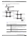
Figure 7-2
ONS 15454 SDH Cards in a 1:N Protection Configuration
7-3
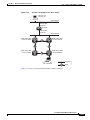
Figure 7-3
ONS 15454 SDH Cards in an Unprotected Configuration
Figure 8-1
CTC Software Versions, Node View
Figure 8-2
CTC Software Versions, Network View
Figure 8-3
Node View (Default Login View)
Figure 8-4
Terminal Loopback Indicator
Figure 8-5
Facility Loopback Indicator
Figure 8-6
CTC Network View
Figure 8-7
CTC Card View
Figure 10-1
ONS 15454 SDH Timing Example
Figure 11-1
ONS 15454 SDH Circuit Window in Network View
Figure 11-2
Terminal Loopback in the Edit Circuits Window
Figure 11-3
Traditional DCC Tunnel
Figure 11-4
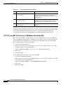
VC4 Monitor Circuit Received at an STM-1 Port
Figure 11-5
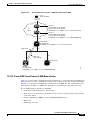
SNCP Go-and-Return Routing
Figure 11-6
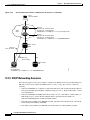
Secondary Sources and Destinations
Figure 11-7
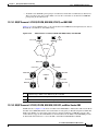
Alternate Paths for Virtual SNCP Segments
Figure 11-8
Mixing 1+1 or MS-SPRing Protected Links with an SNCP
Figure 11-9
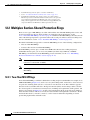
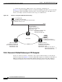
Ethernet Shared Packet Ring Routing
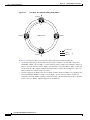
Figure 11-10
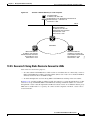
Ethernet and SNCP
5-9
5-12
5-14
5-27
5-28
5-29
5-29
5-30
5-30
6-2
7-5
8-2
8-3
8-8
8-10
8-10
8-12
8-15
10-3
11-4
11-11
11-13
11-14
11-16
11-20
11-21
11-21
11-22
11-22
Cisco ONS 15454 SDH Reference Manual, R7.0
October 2008
xxiii
Figures
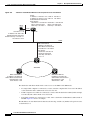
Figure 11-11
VCAT Common Fiber Routing
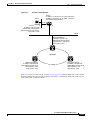
Figure 11-12
VCAT Split Fiber Routing
Figure 11-13
Rolls Window
Figure 11-14
Single Source Roll
Figure 11-15
Single Destination Roll
Figure 11-16
Single Roll from One Circuit to Another Circuit (Destination Changes)
Figure 11-17
Single Roll from One Circuit to Another Circuit (Source Changes)
Figure 11-18
Dual Roll to Reroute a Link
Figure 11-19
Dual Roll to Reroute to a Different Node
Figure 12-1
Four-Node, Two-Fiber MS-SPRing
Figure 12-2
Four-Node, Two-Fiber MS-SPRing Traffic Pattern
Figure 12-3
Four-Node, Two-Fiber MS-SPRing Traffic Pattern After Line Break
Figure 12-4
Four-Node, Four-Fiber MS-SPRing
Figure 12-5
Four-Fiber MS-SPRing Span Switch
Figure 12-6
Four-Fiber MS-SPRing Switch
12-8
Figure 12-7
MS-SPRing Bandwidth Reuse
12-9
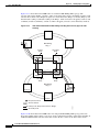
Figure 12-8
Five-Node, Two-Fiber MS-SPRing
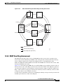
Figure 12-9
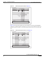
Shelf Assembly Layout for Node 0 in Figure 12-8
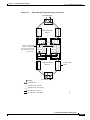
Figure 12-10
Shelf Assembly Layout for Nodes 1 to 4 in Figure 12-8
Figure 12-11
Connecting Fiber to a Four-Node, Two-Fiber MS-SPRing
12-12
Figure 12-12
Connecting Fiber to a Four-Node, Four-Fiber MS-SPRing
12-13
Figure 12-13
Basic Four-Node SNCP Ring
Figure 12-14
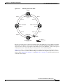
SNCP Ring with a Fiber Break
Figure 12-15
STM-1 SNCP Ring
Figure 12-16
Card Setup of Node A in the STM-1 SNCP Ring Example
Figure 12-17
Card Setup of Nodes B-D in the STM-1 SNCP Ring Example
Figure 12-18
ONS 15454 SDH Traditional MS-SPRing Dual Ring Interconnect (Same-Side Routing)
Figure 12-19
ONS 15454 SDH Traditional MS-SPRing Dual Ring Interconnect (Opposite-Side Routing)
Figure 12-20
ONS 15454 SDH Integrated MS-SPRing Dual Ring Interconnect
Figure 12-21
ONS 15454 Traditional SDH Dual Ring Interconnect
12-22
Figure 12-22
ONS 15454 SDH Integrated Dual Ring Interconnect
12-23
Figure 12-23
ONS 15454 SDH SNCP to MS-SPRing Traditional DRI Handoff
12-24
Figure 12-24
ONS 15454 SDH SNCP to MS-SPRing Integrated DRI Handoff
12-25
Figure 12-25
ONS 15454 SDH with Multiple Subtending Rings
Figure 12-26
SNCP Ring Subtending from an MS-SPRing
11-26
11-26
11-29
11-31
11-31
11-31
11-31
11-32
11-32
12-3
12-4
12-5
12-6
12-7
12-10
12-11
12-11
12-14
12-15
12-16
12-17
12-17
12-19
12-20
12-21
12-26
12-26
Cisco ONS 15454 SDH Reference Manual, R7.0
xxiv
October 2008
Figures
Figure 12-27
MS-SPRing Subtending from an MS-SPRing
Figure 12-28
Linear (Point-to-Point) ADM Configuration
Figure 12-29
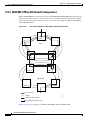
Extended SNCP Mesh Network
Figure 12-30
Extended SNCP Virtual Ring
Figure 13-1
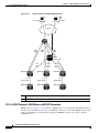
Scenario 1: CTC and ONS 15454 SDH Nodes on the Same Subnet
13-3
Figure 13-2
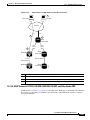
Scenario 2: CTC and ONS 15454 SDH Nodes Connected to Router
13-4
Figure 13-3
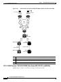
Scenario 3: Using Proxy ARP
Figure 13-4
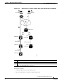
Scenario 3: Using Proxy ARP with Static Routing
13-6
Figure 13-5
Scenario 4: Default Gateway on a CTC Computer
13-7
Figure 13-6
Scenario 5: Static Route With One CTC Computer Used as a Destination
Figure 13-7
Scenario 5: Static Route With Multiple LAN Destinations
Figure 13-8
Scenario 6: OSPF Enabled
Figure 13-9
Scenario 6: OSPF Not Enabled
Figure 13-10
Proxy Server Gateway Settings
Figure 13-11
Scenario 7: SDH Proxy Server with GNE and ENEs on the Same Subnet
Figure 13-12
Scenario 7: ONS 15454 SDH Proxy Server with GNE and ENEs on Different Subnets
Figure 13-13
Scenario 7: ONS 15454 SDH Proxy Server With ENEs on Multiple Rings
Figure 13-14
Scenario 8: Dual GNEs on the Same Subnet
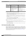
13-19
Figure 13-15
Scenario 8: Dual GNEs on Different Subnets
13-20
Figure 13-16
Scenario 9: ONS 15454 SDH GNE and ENEs on the Same Subnet with Secure Mode Enabled
13-21
Figure 13-17
Scenario 9: ONS 15454 SDH GNE and ENEs on Different Subnets with Secure Mode Enabled
13-22
Figure 13-18
Proxy and Firewall Tunnels for Foreign Terminations
Figure 13-19
Foreign Node Connection to an ENE Ethernet Port
Figure 13-20
ISO-DCC NSAP Address
Figure 13-21
Level 1 and Level 2 OSI Routing
Figure 13-22
Manual TARP Adjacencies
Figure 13-23
T–TD Protocol Flow
Figure 13-24
FT–TD Protocol Flow
Figure 13-25
IP-over-CLNS Tunnel Flow
Figure 13-26
IP-over-CLNS Tunnel Scenario 1: ONS NE to Other Vender GNE
Figure 13-27
IP-over-CLNS Tunnel Scenario 2: ONS Node to Router
Figure 13-28
IP-over-CLNS Tunnel Scenario 3: ONS Node to Router Across an OSI DCN
Figure 13-29
OSI/IP Scenario 1: IP OSS, IP DCN, ONS GNE, IP DCC, and ONS ENE
Figure 13-30
OSI/IP Scenario 2: IP OSS, IP DCN, ONS GNE, OSI DCC, and Other Vendor ENE
13-50
Figure 13-31
OSI/IP Scenario 3: IP OSS, IP DCN, Other Vendor GNE, OSI DCC, and ONS ENE
13-52
12-27
12-28
12-29
12-29
13-5
13-8
13-9
13-11
13-12
13-14
13-15
13-16
13-17
13-29
13-30
13-34
13-36
13-40
13-41
13-41
13-43
13-45
13-46
13-48
13-49
Cisco ONS 15454 SDH Reference Manual, R7.0
October 2008
xxv
Figures
Figure 13-32
OSI/IP Scenario 3 with OSI/IP-over-CLNS Tunnel Endpoint at the GNE
Figure 13-33
OSI/IP Scenario 4: Multiple ONS DCC Areas
Figure 13-34
OSI/IP Scenario 5: GNE Without an OSI DCC Connection
Figure 13-35
OSI/IP Scenario 6: IP OSS, OSI DCN, ONS GNE, OSI DCC, and Other Vendor ENE
Figure 13-36
OSI/IP Scenario 7: OSI OSS, OSI DCN, Other Vender GNE, OSI DCC, and ONS NEs
13-57
Figure 13-37
OSI/IP Scenario 8: OSI OSS, OSI DCN, ONS GNE, OSI DCC, and Other Vender NEs
13-59
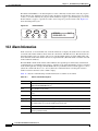
Figure 14-1
Shelf LCD Panel
Figure 14-2
Select Affected Circuits Option
Figure 14-3
Alarm Profile for an STM-1 Card
Figure 15-1
TCAs Displayed in CTC
Figure 15-2
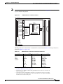
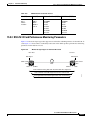
Monitored Signal Types for the E1-N-14 Card and E1-42 Card
Figure 15-3
PM Read Points on the E1-N-14 Card
Figure 15-4
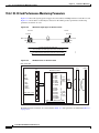
Monitored Signal Types for the E3-12 Card
Figure 15-5
PM Read Points on the E3-12 Card
Figure 15-6
Monitored Signal Types for the DS3i-N-12 Card
Figure 15-7
PM Read Points on the DS3i-N-12 Card
Figure 15-8
PM Read Points on the STM-1 Cards
Figure 15-9
PM Read Points on the STM-1E Cards
Figure 15-10
PM Read Points on the STM-1E Cards in E4 Mode
Figure 15-11
Monitored Signal Types for the STM-4 Cards
Figure 15-12
PM Read Points on the STM-4 Cards
Figure 15-13
Monitored Signal Types for STM-16 and STM-64 Cards
Figure 15-14
PM Read Points on STM-16 and STM-64 Cards
Figure 15-15
PM Read Points for the MRC-12 Card
Figure 16-1
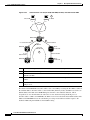
Basic Network Managed by SNMP
Figure 16-2
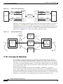
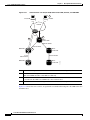
Example of the Primary SNMP Components
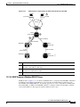
Figure 16-3
Agent Gathering Data from a MIB and Sending Traps to the Manager
13-53
13-54
13-55
13-56
14-2
14-6
14-14
15-2
15-14
15-15
15-16
15-16
15-17
15-18
15-32
15-34
15-35
15-36
15-36
15-37
15-38
15-40
16-2
16-3
16-3
Cisco ONS 15454 SDH Reference Manual, R7.0
xxvi
October 2008
T A B L E S
Table 1-1
Slot and FMEC Symbols
Table 1-2
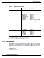
FMEC, Ports, Line Rates, and Connectors
Table 1-3
E100-TX Connector Pinout
Table 1-4
Fiber Channel Capacity (One Side of the Shelf)
Table 1-5
Slot and Card Symbols
Table 1-6
Card Ports, Line Rates, and Connectors
Table 1-7
ONS 15454 SDH Software Release/Hardware Compatibility—XC-VXL-2.5G Configurations
Table 1-8
ONS 15454 SDH Software Release/Hardware Compatibility—XC10G, XC-VXC-10G, and XC-VXL-10G
Configuration 1-22
Table 2-1
Common Control Cards for the ONS 15454 SDH
Table 2-2
Common-Control Card Software Release Compatibility
Table 2-3
Common-Control Card Cross-Connect Compatibility
Table 2-4
Electrical Card Cross-Connect Compatibility
Table 2-5
Optical Card Cross-Connect Compatibility
Table 2-6
Ethernet Card Cross-Connect Compatibility
Table 2-7
SAN Card Cross-Connect Compatibility
Table 2-8
TCC2 Card-Level Indicators
Table 2-9
TCC2 Network-Level Indicators
Table 2-10
TCC2 Power-Level Indicators
Table 2-11
BITS Clocks
Table 2-12
TCC2P Card-Level Indicators
Table 2-13
TCC2P Network-Level Indicators
Table 2-14
TCC2P Power-Level Indicators
Table 2-15
XC-VXL-10G Card-Level Indicators
2-15
Table 2-16
XC-VXL-2.5G Card-Level Indicators
2-17
Table 2-17
XC-VXC-10G Card-Level Indicators
2-20
Table 2-18
AIC-I Card-Level Indicators
2-22
Table 2-19
Orderwire Pin Assignments
2-24
Table 2-20
UDC Pin Assignments
2-25
Table 2-21
GCC Pin Assignments
2-25
Table 3-1
Electrical Cards
Table 3-2
Electrical Card Software Release Compatibility
1-8
1-8
1-11
1-14
1-18
1-18
1-20
2-2
2-3
2-3
2-3
2-4
2-4
2-5
2-8
2-8
2-9
2-11
2-12
2-12
2-13
3-2
3-4
Cisco ONS 15454 SDH Reference Manual, R7.0
October 2008
xxvii
Tables
Table 3-3
E1-N-14 Card-Level Indicators
Table 3-4
E1-42 Card-Level Indicators
3-8
Table 3-5
E3-12 Card-Level Indicators
3-10
Table 3-6
DS3i-N-12 Card-Level Indicators
3-12
Table 3-7
STM1E-12 Card-Level Indicators
3-14
Table 3-8
E-1 Interface Pinouts on the FMEC-DS1/E1 Card Ports 1 to 7
Table 3-9
E-1 Interface Pinouts on the FMEC-DS1/E1 Card Ports 8 to 14
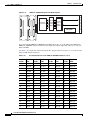
Table 3-10
E-1 Interface Pinouts on the FMEC E1-120NP Card Ports 1 to 21
Table 3-11
E-1 Interface Pinouts on the FMEC E1-120NP Card Ports 22 to 42
Table 3-12
E-1 Interface Pinouts on the FMEC E1-120PROA Card Ports 1 to 21
Table 3-13
E-1 Interface Pinouts on the FMEC E1-120PROA Card Ports 22 to 42
Table 3-14
E-1 Interface Pinouts on the FMEC E1-120PROB Card Ports 1 to 21
Table 3-15
E-1 Interface Pinouts on the FMEC E1-120PROB Card Ports 22 to 42
Table 3-16
Alarm Interface Pinouts on the MIC-A/P DB-62 Connector
Table 4-1
Optical Cards for the ONS 15454 SDH
Table 4-2
Optical Card Software Release Compatibility
Table 4-3
OC3 IR 4/STM1 SH 1310 Card-Level Indicators
4-6
Table 4-4
OC3IR/STM1 SH 1310-8 Card-Level Indicators
4-8
Table 4-5
OC12 IR/STM4 SH 1310 Card-Level Indicators
4-10
Table 4-6
OC12 LR/STM4 LH 1310 Card-Level Indicators
4-12
Table 4-7
OC12 LR/STM4 LH 1550 Card-Level Indicators
4-14
Table 4-8
OC12 IR/STM4 SH 1310-4 Card-Level Indicators
Table 4-9
OC48 IR/STM16 SH AS 1310 Card-Level Indicators
4-18
Table 4-10
OC48 LR/STM16 LH AS 1550 Card-Level Indicators
4-20
Table 4-11
OC48 ELR Card-Level Indicators
Table 4-12
OC192 SR/STM64 IO 1310 Card-Level Indicators
4-24
Table 4-13
OC192 IR/STM64 SH 1550 Card-Level Indicators
4-26
Table 4-14
OC192 LR/STM64 LH 1550 Card-Level Indicators
4-30
Table 4-15
OC192 LR/STM64 LH ITU 15xx.xx Card-Level Indicators
Table 4-16
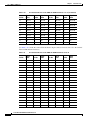
Maximum Bandwidth by Shelf Slot for the 15454_MRC-12 in Different Cross-Connect Configurations
Table 4-17
Line Rate Configurations Per 15454_MRC-12 Port, Based on Available Bandwidth
Table 4-18
15454_MRC-12 Card-Level Indicators
Table 4-19
OC192SR1/STM64IO Short Reach and OC192/STM64 Any Reach Card-Level Indicators
Table 4-20
SFP and XFP Card Compatibility
Table 5-1
Ethernet Cards for the ONS 15454 SDH
3-6
3-17
3-18
3-19
3-20
3-22
3-22
3-24
3-25
3-31
4-2
4-4
4-16
4-22
4-33
4-35
4-36
4-38
4-40
4-41
5-2
Cisco ONS 15454 SDH Reference Manual, R7.0
xxviii
October 2008
Tables
Table 5-2
Ethernet Card Software Compatibility
Table 5-3
E100T-G Card-Level Indicators
5-5
Table 5-4
E100T-G Port-Level Indicators
5-5
Table 5-5
E1000-2-G Card-Level Indicators
5-8
Table 5-6
E1000-2-G Port-Level Indicators
5-8
Table 5-7
G1000-4 Card-Level Indicators
5-10
Table 5-8
G1000-4 Port-Level Indicators
5-11
Table 5-9
G1K-4 Card-Level Indicators
5-13
Table 5-10
G1K-4 Port-Level Indicators
5-13
Table 5-11
ML100T-12 Card-Level Indicators
5-15
Table 5-12
ML100T-12 Port-Level Indicators
5-15
Table 5-13
ML100X-8 Card-Level Indicators
5-17
Table 5-14
ML100X-8 Port-Level Indicators
5-17
Table 5-15
ML1000-2 Card-Level Indicators
5-19
Table 5-16
ML1000-2 Port-Level Indicators
5-19
Table 5-17
CE-100T-8 Card-Level Indicators
5-21
Table 5-18
CE-100T-8 Port-Level Indicators
5-21
Table 5-19
CE-1000-4 Card-Level Indicators
5-24
Table 5-20
CE-1000-4 Port-Level Indicators
5-25
Table 5-21
GBIC and SFP Card Compatibility
Table 5-22
Supported Wavelengths for CWDM GBICs
5-27
Table 5-23
Supported Wavelengths for DWDM GBICs
5-28
Table 6-1
FC_MR-4 Card-Level Indicators
Table 6-2
GBIC Compatibility
Table 8-1
JRE Compatibility
Table 8-2
CTC Computer Requirements
Table 8-3
ONS 15454 SDH Connection Methods
Table 8-4
Node View Card Colors
8-8
Table 8-5
Node View FMEC Color
8-9
Table 8-6
Node View Card Port Colors and Service States
Table 8-7
Node View Card States
Table 8-8
Node View Port Graphics
Table 8-9
Node View Tabs and Subtabs
Table 8-10
Node Status Shown in Network View
Table 8-11
Network View Tabs and Subtabs
5-3
5-26
6-3
6-7
8-4
8-5
8-7
8-9
8-10
8-11
8-11
8-13
8-13
Cisco ONS 15454 SDH Reference Manual, R7.0
October 2008
xxix
Tables
Table 8-12
Link Icons
Table 8-13
Card View Tabs and Subtabs
Table 9-1
ONS 15454 SDH Security Levels—Node View
Table 9-2
ONS 15454 SDH Security Levels—Network View
Table 9-3
ONS 15454 SDH Default User Idle Times
Table 9-4
Audit Trail Window Columns
Table 9-5
Shared Secret Character Groups
Table 10-1
SDH SSM Message Set
10-3
Table 11-1
VC4 Mapping Using CTC
11-4
Table 11-2
ONS 15454 SDH Circuit Status
Table 11-3
Circuit Protection Types
Table 11-4
Port State Color Indicators
Table 11-5
DCC Tunnels
Table 11-6
ONS 15454 SDH Cards Capable of J1 Path Trace
11-17
Table 11-7
ONS 15454 SDH Cards Capable of J2 Path Trace
11-18
Table 11-8
STM Path Signal Label Assignments for Signals
Table 11-9
Bidirectional VC/TUG/Regular Multicard EtherSwitch/Point-to-Point (Straight) Ethernet Circuits
Table 11-10
Unidirectional Circuit
Table 11-11
Multicard Group Ethernet Shared Packet Ring Circuit
Table 11-12
Bidirectional Low-Order Tunnels
Table 11-13
ONS 15454 SDH Card VCAT Circuit Rates and Members
Table 11-14
ONS 15454 SDH VCAT Card Capabilities
Table 11-15
Roll Statuses
Table 12-1
ONS 15454 SDH Rings with Redundant TCC2/TCC2P Cards
Table 12-2
Two-Fiber MS-SPRing Capacity
12-8
Table 12-3
Four-Fiber MS-SPRing Capacity
12-9
Table 13-1
General ONS 15454 SDH IP Troubleshooting Checklist
Table 13-2
ONS 15454 SDH GNE and ENE Settings
Table 13-3
Proxy Server Firewall Filtering Rules
Table 13-4
Proxy Server Firewall Filtering Rules When Packet Addressed to ONS 15454 SDH
Table 13-5
Client-to-Trunk Card Combinations for Provisionable Patchcords
13-23
Table 13-6
Client-to-Client Card Combinations for Provisionable Patchcords
13-23
Table 13-7
Trunk-to-Trunk Card Combinations for Provisionable Patchcords
13-23
Table 13-8
Sample Routing Table Entries
Table 13-9
Ports Used by the TCC2/TCC2P
8-14
8-15
9-2
9-5
9-6
9-7
9-9
11-6
11-9
11-10
11-12
11-18
11-22
11-23
11-23
11-23
11-27
11-28
11-30
12-1
13-2
13-15
13-17
13-18
13-24
13-26
Cisco ONS 15454 SDH Reference Manual, R7.0
xxx
October 2008
Tables
Table 13-10
TCP/IP and OSI Protocols
Table 13-11
NSAP Fields
Table 13-12
TARP PDU Fields
13-37
Table 13-13
TARP PDU Types
13-38
Table 13-14
TARP Timers
Table 13-15
TARP Processing Flow
Table 13-16
OSI Virtual Router Constraints
Table 13-17
IP-over-CLNS Tunnel IOS Commands
Table 13-18
OSI Actions from the CTC Provisioning Tab
Table 13-19
OSI Actions from the CTC Maintenance Tab
Table 14-1
Alarms Column Descriptions
Table 14-2
Color Codes for Alarm and Condition Severities
Table 14-3
Release 4.0 and Later Port-Based Alarm Numbering Scheme
Table 14-4
Alarm Display
Table 14-5
Conditions Display
Table 14-6
Conditions Column Description
Table 14-7
History Column Description
Table 14-8
Alarm Profile Buttons
Table 14-9
Alarm Profile Editing Options
Table 15-1
Electrical Cards that Report RX and TX Direction for TCAs
Table 15-2
Line Terminating Equipment (LTE)
Table 15-3
Performance Monitoring Parameters
Table 15-4
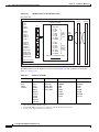
PM Parameters for the E1-N-14 Card and E1-42 Card
Table 15-5
PM Parameters for the E3-12 Card
Table 15-6
DS3i-N-12 Card PMs
Table 15-7
E-Series Ethernet Statistics Parameters
Table 15-8
MaxBaseRate for VC Circuits
Table 15-9
Ethernet Statistics History per Time Interval
Table 15-10
G-Series Ethernet Statistics Parameters
Table 15-11
ML-Series Ether Ports PM Parameters
Table 15-12
ML-Series POS Ports Parameters for HDLC Mode
15-25
Table 15-13
ML-Series POS Ports Parameters for GFP-F Mode
15-25
Table 15-14
CE-Series Ether Ports PM Parameters
Table 15-15
CE-Series POS Ports Statistics Parameters
Table 15-16
PM Parameters for the STM-1 and STM1 SH 1310-8 Cards
13-31
13-33
13-39
13-39
13-42
13-44
13-60
13-60
14-2
14-3
14-4
14-4
14-7
14-7
14-9
14-12
14-12
15-2
15-3
15-5
15-15
15-17
15-18
15-19
15-20
15-21
15-21
15-23
15-27
15-30
15-33
Cisco ONS 15454 SDH Reference Manual, R7.0
October 2008
xxxi
Tables
Table 15-17
PM Parameters for the STM-1E Cards
Table 15-18
PM Parameters for STM-4 Cards
Table 15-19
PM Parameters for STM-16 and STM-64 Cards
Table 15-20
Table of Border Error Rates
Table 15-21
MRC-12 Card PMs
Table 15-22
maxBaseRate for STS Circuits
Table 15-23
FC_MR-4 History Statistics per Time Interval
Table 16-1
ONS 15454 SDH SNMP Message Types
Table 16-2
IETF Standard MIBs Implemented in the ONS 15454 SDH System
Table 16-3
ONS 15454 SDH Proprietary MIBs
Table 16-4
cerentGenericPmThresholdTable
Table 16-5
cerentGenericPmStatsCurrentTable
16-8
Table 16-6
cerentGenericPmStatsIntervalTable
16-8
Table 16-7
ONS 15454 SDH Traps
Table 16-8
ONS 15454 SDH SNMPv2 Trap Variable Bindings
Table 16-9
RMON History Control Periods and History Categories
Table 16-10
OIDs Supported in the Alarm Table
Table A-1
SFP and XFP Specifications
Table A-2
Individual Card Power Requirements
Table A-3
Card Temperature Ranges and Product Names
Table B-1
ONS 15454 SDH Service State Primary States and Primary State Qualifiers
Table B-2
ONS 15454 SDH Secondary States
Table B-3
ONS 15454 SDH Administrative States
Table B-4
ONS 15454 SDH Card Service State Transitions
Table B-5
ONS 15454 SDH Port and Cross-Connect Service State Transitions
Table C-1
E1-N-14 Card Default Settings
Table C-2
E1-42 Card Default Settings
C-6
Table C-3
E3-12 Card Default Settings
C-8
Table C-4
DS3i-N-12 Card Default Settings
C-9
Table C-5
STM1E-12 Card Default Settings
C-12
Table C-6
Ethernet Card Default Settings
Table C-7
STM-1 Card Default Settings
Table C-8
STM1-8 Card Default Settings
Table C-9
STM-4 Card Default Settings
Table C-10
STM4-4 Card Default Settings
15-35
15-37
15-38
15-39
15-40
15-42
15-43
16-4
16-5
16-6
16-7
16-9
16-10
16-19
16-21
A-4
A-6
A-8
B-1
B-2
B-3
B-3
B-7
C-4
C-14
C-15
C-17
C-21
C-23
Cisco ONS 15454 SDH Reference Manual, R7.0
xxxii
October 2008
Tables
Table C-11
STM-16 Card Default Settings
C-25
Table C-12
STM-64 Card Default Settings
C-28
Table C-13
STM64-XFP Default Settings
Table C-14
MRC-12 Card Default Settings
Table C-15
FC_MR-4 Card Default Settings
Table C-16
Node Default Settings
Table C-17
Time Zones
Table C-18
CTC Default Settings
C-31
C-35
C-45
C-47
C-55
C-58
Cisco ONS 15454 SDH Reference Manual, R7.0
October 2008
xxxiii
Tables
Cisco ONS 15454 SDH Reference Manual, R7.0
xxxiv
October 2008
About this Manual
Note
The terms "Unidirectional Path Switched Ring" and "UPSR" may appear in Cisco literature. These terms
do not refer to using Cisco ONS 15xxx products in a unidirectional path switched ring configuration.
Rather, these terms, as well as "Path Protected Mesh Network" and "PPMN," refer generally to Cisco's
path protection feature, which may be used in any topological network configuration. Cisco does not
recommend using its path protection feature in any particular topological network configuration.
This section explains the objectives, intended audience, and organization of this publication and
describes the conventions that convey instructions and other information.
This section provides the following information:
•
Revision History
•
Document Objectives
•
Audience
•
Document Organization
•
Related Documentation
•
Document Conventions
•
Obtaining Optical Networking Information
•
Obtaining Documentation and Submitting a Service Request
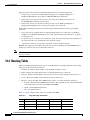
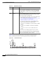
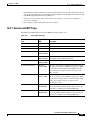
Revision History
Date
Notes
March 2007
Revision History Table added for the first time.
April 2007
Corrected product part numbers for the UBIC-V and UBIC-H DS3 cables. Added
note to indicate the support for LO circuits in SNCP in XC-VXC-10G card.
August 2007
Updated the note in the SNCP Circuits section of the Circuits and Tunnels chapter.
Updated About this Manual chapter.
October 2007
Added a table with border error rates and a corresponding Note in the
Performance Monitoring chapter.
Cisco ONS 15454 SDH Reference Manual, R7.0
October 2008
xxxv
About this Manual
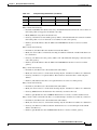
Date
Notes
April 2008
Added a note in the “User Password, Login, and Access Policies” section in the
Security chapter.
Updated note on protection switching in “Link Capacity Adjustment” section of
Chapter 11, Circuits and Tunnels.
May 2008
Added power-level LED information for TCC2 and TCC2P cards in Chapter 2,
Common Control Cards.
July 2008
Updated the section “15454_MRC-12 Port-Level Indicators” in the Optical Cards
chapter, to show the correct number and status of the Rx indicator.
Added a note in section 10.1 “Timing Parameters” section of Chapter 10, Timing.
September 2008
Added a Warning for all optical cards in Chapter 4, Optical Cards.
Added a note in Card Default Settings and Node Default Settings section of
Appendix C, Network Element Defaults.
Updated the maximum current rating and fusing in section “A.1.9 System Power”
of Appendix A, Hardware Specifications.
Updated FC_MR-4 Statistics Parameters table in the chapter, Performance
Monitoring.
Updated “Table 4-17 Line Rate Configurations Per 15454_MRC-12 Port, Based
on Available Bandwidth” in Chapter 4, Optical Cards.
Updated the Software and Hardware Compatibility section.
October 2008
Updated the section “4.15.2 Ports and Line Rates” and “Table 4-17 Line Rate
Configurations Per 15454_MRC-12 Port, Based on Available Bandwidth” in
Chapter 4, Optical Cards.
Document Objectives
This manual provides reference information for the Cisco ONS 15454 SDH.
Audience
To use this publication, you should be familiar with Cisco or equivalent optical transmission hardware
and cabling, telecommunications hardware and cabling, electronic circuitry and wiring practices, and
preferably have experience as a telecommunications technician.
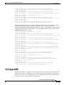
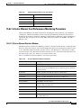
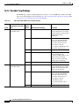
Document Organization
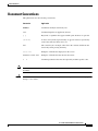
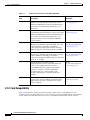
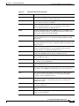
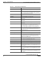
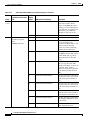
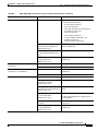
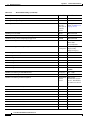
Table 1 lists the chapter titles and provides a summary for each chapter.
Cisco ONS 15454 SDH Reference Manual, R7.0
xxxvi
October 2008
About this Manual
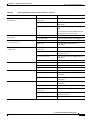
Table 1
Cisco ONS 15454 SDH Reference Manual Chapters
Title
Summary
Chapter 1, “Shelf and FMEC Hardware”
Includes descriptions of the rack, ferrites, power
and ground, fan-tray assembly, air filter, card slots,
cable, cable connectors, and cable routing.
Chapter 2, “Common Control Cards”
Includes descriptions of the TCC2P, XC10G,
XC-VXL, and AIC-I cards.
Chapter 3, “Electrical Cards”
Includes descriptions of E1-N-14, E1-42, E3-12,
DS3i-N-12, STM1E-12, FMEC cards, MIC cards,
card temperature ranges, and compatibility.
Chapter 4, “Optical Cards”
Includes descriptions of the STM1-4, STM1-8,
STM-4, STM4-4, STM-16, STM-64, TXP_MR,
TXPP_MR, and MXP cards, as well as card
temperature ranges and card compatibility.
Chapter 5, “Ethernet Cards”
Includes descriptions of the E100T-G, E1000-2-G,
G1000-4, G1K-4, CE-100T-8, ML100T-12,
ML1000-2, and ML100X-8 cards, gigabit interface
converters (GBICs) and small form-factor
pluggables (SFPs).
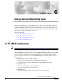
Chapter 6, “Storage Access Networking Cards”
Includes the FC_MR-4 card description and
application.
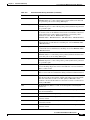
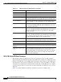
Chapter 7, “Card Protection”
Includes electrical, optical, and transponder and
muxponder card protection methods, as well as
external switching commands.
Chapter 8, “Cisco Transport Controller
Operation”
Includes information about CTC delivery,
installation, computer requirements, connection,
the CTC window, and database reset and revert.
Chapter 9, “Security”
Includes user set up, security parameters and
profiles, audit trail information, and RADIUS
authentication information.
Chapter 10, “Timing”
Includes node and network timing information.
Chapter 11, “Circuits and Tunnels”
Includes descriptions of circuit properties,
cross-connect card bandwidth usage, data
communications channel (DCC) and
IP-encapsulated tunnels, multiple destination
circuits, circuit monitoring, subnetwork
connection protection (SNCP) and multiplex
section-shared protection rings (MS-SPRing)
circuits, J1 path trace, path signal labels, manual
and automatic circuit routing, and virtual
concatenated (VCAT) circuits.
Chapter 12, “SDH Topologies and Upgrades”
Includes the SDH configurations used by the
ONS 15454 SDH; including MS-SPRings, SNCPs,
subtending rings, linear ADMs, and optical bus
configurations, as well as information about
upgrading optical speeds within any configuration.
Cisco ONS 15454 SDH Reference Manual, R7.0
October 2008
xxxvii
About this Manual
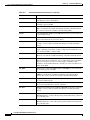
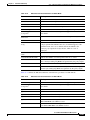
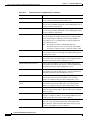
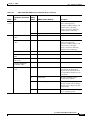
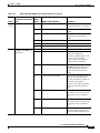
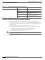
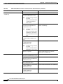
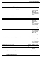
Table 1
Cisco ONS 15454 SDH Reference Manual Chapters (continued)
Title
Summary
Chapter 13, “Management Network
Connectivity”
Provides an overview of ONS 15454 SDH data
communications network (DCN) connectivity,
scenarios showing Cisco ONS 15454 SDH nodes
in common IP network configurations, and
information about provisionable patchcords, the IP
routing table, external firewalls, and open gateway
network element (GNE) networks.
Chapter 14, “Alarm Monitoring and
Management”
Explains alarm, condition, and history display;
severities; profiles; suppression; external alarms;
and the audit trail.
Chapter 15, “Performance Monitoring”
Provides performance-monitoring parameters for
all ONS 15454 SDH cards.
Chapter 16, “SNMP”
Describes simple network management protocol
(SNMP) as it applies to the ONS 15454 SDH.
Appendix A, “Hardware Specifications”
Provides specifications for the ONS 15454 SDH
shelf assembly and cards.
Appendix B, “Administrative and Service States” Describes the extended state model for cards,
ports, and cross-connects.
Appendix C, “Network Element Defaults”
Lists card, node, and CTC-level network element
(NE) defaults.
Related Documentation
Use the Cisco ONS 15454 SDH Reference Manual with the following referenced publications:
•
Cisco ONS 15454 SDH Procedure Guide
Provides procedures to install, turn up, provision, and maintain a Cisco ONS 15454 SDH node and
network.
•
Cisco ONS 15454 SDH Troubleshooting Guide
Provides general troubleshooting procedures, alarm descriptions and troubleshooting procedures,
error messages, and transient conditions.
•
Cisco ONS 15454 SDH TL1 Command Guide
Provides a full TL1 command and autonomous message set including parameters, AIDs, conditions
and modifiers for the Cisco ONS 15454 SDH.
•
Cisco ONS 15454 SDH TL1 Reference Guide
Provides general information, procedures, and errors for TL1 in the Cisco ONS 15454 SDH.
•
Ethernet Card Software Feature and Configuration G uide for the Cisco ONS 15454, Cisco ONS
15454 SDH, and Cisco ONS 15327
Provides software features for all Ethernet cards and configuration information for Cisco IOS on
ML-Series cards.
•
Release Notes for the Cisco ONS 15454 SDH Release 7.0
Provides caveats, closed issues, and new feature and functionality information.
For an update on End-of-Life and End-of-Sale notices, refer to
http://cisco.com/en/US/products/hw/optical/ps2006/prod_eol_notices_list.html.
Cisco ONS 15454 SDH Reference Manual, R7.0
xxxviii
October 2008
About this Manual
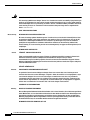
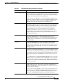
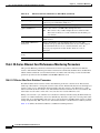
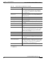
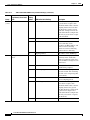
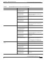
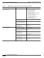
Document Conventions
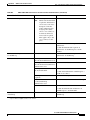
This publication uses the following conventions:
Convention
Application
boldface
Commands and keywords in body text.
italic
Command input that is supplied by the user.
[
Keywords or arguments that appear within square brackets are optional.
]
{x|x|x}
A choice of keywords (represented by x) appears in braces separated by
vertical bars. The user must select one.
Ctrl
The control key. For example, where Ctrl + D is written, hold down the
Control key while pressing the D key.
screen font
Examples of information displayed on the screen.
boldface screen font
Examples of information that the user must enter.
<
Command parameters that must be replaced by module-specific codes.
>
Note
Means reader take note. Notes contain helpful suggestions or references to material not covered in the
document.
Caution
Means reader be careful. In this situation, the user might do something that could result in equipment
damage or loss of data.
Cisco ONS 15454 SDH Reference Manual, R7.0
October 2008
xxxix
About this Manual
Warning
IMPORTANT SAFETY INSTRUCTIONS
This warning symbol means danger. You are in a situation that could cause bodily injury. Before you
work on any equipment, be aware of the hazards involved with electrical circuitry and be familiar
with standard practices for preventing accidents. Use the statement number provided at the end of
each warning to locate its translation in the translated safety warnings that accompanied this
device. Statement 1071
SAVE THESE INSTRUCTIONS
Waarschuwing
BELANGRIJKE VEILIGHEIDSINSTRUCTIES
Dit waarschuwingssymbool betekent gevaar. U verkeert in een situatie die lichamelijk letsel kan
veroorzaken. Voordat u aan enige apparatuur gaat werken, dient u zich bewust te zijn van de bij
elektrische schakelingen betrokken risico's en dient u op de hoogte te zijn van de standaard
praktijken om ongelukken te voorkomen. Gebruik het nummer van de verklaring onderaan de
waarschuwing als u een vertaling van de waarschuwing die bij het apparaat wordt geleverd, wilt
raadplegen.
BEWAAR DEZE INSTRUCTIES
Varoitus
TÄRKEITÄ TURVALLISUUSOHJEITA
Tämä varoitusmerkki merkitsee vaaraa. Tilanne voi aiheuttaa ruumiillisia vammoja. Ennen kuin
käsittelet laitteistoa, huomioi sähköpiirien käsittelemiseen liittyvät riskit ja tutustu
onnettomuuksien yleisiin ehkäisytapoihin. Turvallisuusvaroitusten käännökset löytyvät laitteen
mukana toimitettujen käännettyjen turvallisuusvaroitusten joukosta varoitusten lopussa näkyvien
lausuntonumeroiden avulla.
SÄILYTÄ NÄMÄ OHJEET
Attention
IMPORTANTES INFORMATIONS DE SÉCURITÉ
Ce symbole d'avertissement indique un danger. Vous vous trouvez dans une situation pouvant
entraîner des blessures ou des dommages corporels. Avant de travailler sur un équipement, soyez
conscient des dangers liés aux circuits électriques et familiarisez-vous avec les procédures
couramment utilisées pour éviter les accidents. Pour prendre connaissance des traductions des
avertissements figurant dans les consignes de sécurité traduites qui accompagnent cet appareil,
référez-vous au numéro de l'instruction situé à la fin de chaque avertissement.
CONSERVEZ CES INFORMATIONS
Warnung
WICHTIGE SICHERHEITSHINWEISE
Dieses Warnsymbol bedeutet Gefahr. Sie befinden sich in einer Situation, die zu Verletzungen führen
kann. Machen Sie sich vor der Arbeit mit Geräten mit den Gefahren elektrischer Schaltungen und
den üblichen Verfahren zur Vorbeugung vor Unfällen vertraut. Suchen Sie mit der am Ende jeder
Warnung angegebenen Anweisungsnummer nach der jeweiligen Übersetzung in den übersetzten
Sicherheitshinweisen, die zusammen mit diesem Gerät ausgeliefert wurden.
BEWAHREN SIE DIESE HINWEISE GUT AUF.
Cisco ONS 15454 SDH Reference Manual, R7.0
xl
October 2008
About this Manual
Avvertenza
IMPORTANTI ISTRUZIONI SULLA SICUREZZA
Questo simbolo di avvertenza indica un pericolo. La situazione potrebbe causare infortuni alle
persone. Prima di intervenire su qualsiasi apparecchiatura, occorre essere al corrente dei pericoli
relativi ai circuiti elettrici e conoscere le procedure standard per la prevenzione di incidenti.
Utilizzare il numero di istruzione presente alla fine di ciascuna avvertenza per individuare le
traduzioni delle avvertenze riportate in questo documento.
CONSERVARE QUESTE ISTRUZIONI
Advarsel
VIKTIGE SIKKERHETSINSTRUKSJONER
Dette advarselssymbolet betyr fare. Du er i en situasjon som kan føre til skade på person. Før du
begynner å arbeide med noe av utstyret, må du være oppmerksom på farene forbundet med
elektriske kretser, og kjenne til standardprosedyrer for å forhindre ulykker. Bruk nummeret i slutten
av hver advarsel for å finne oversettelsen i de oversatte sikkerhetsadvarslene som fulgte med denne
enheten.
TA VARE PÅ DISSE INSTRUKSJONENE
Aviso
INSTRUÇÕES IMPORTANTES DE SEGURANÇA
Este símbolo de aviso significa perigo. Você está em uma situação que poderá ser causadora de
lesões corporais. Antes de iniciar a utilização de qualquer equipamento, tenha conhecimento dos
perigos envolvidos no manuseio de circuitos elétricos e familiarize-se com as práticas habituais de
prevenção de acidentes. Utilize o número da instrução fornecido ao final de cada aviso para
localizar sua tradução nos avisos de segurança traduzidos que acompanham este dispositivo.
GUARDE ESTAS INSTRUÇÕES
¡Advertencia!
INSTRUCCIONES IMPORTANTES DE SEGURIDAD
Este símbolo de aviso indica peligro. Existe riesgo para su integridad física. Antes de manipular
cualquier equipo, considere los riesgos de la corriente eléctrica y familiarícese con los
procedimientos estándar de prevención de accidentes. Al final de cada advertencia encontrará el
número que le ayudará a encontrar el texto traducido en el apartado de traducciones que acompaña
a este dispositivo.
GUARDE ESTAS INSTRUCCIONES
Varning!
VIKTIGA SÄKERHETSANVISNINGAR
Denna varningssignal signalerar fara. Du befinner dig i en situation som kan leda till personskada.
Innan du utför arbete på någon utrustning måste du vara medveten om farorna med elkretsar och
känna till vanliga förfaranden för att förebygga olyckor. Använd det nummer som finns i slutet av
varje varning för att hitta dess översättning i de översatta säkerhetsvarningar som medföljer denna
anordning.
SPARA DESSA ANVISNINGAR
Cisco ONS 15454 SDH Reference Manual, R7.0
October 2008
xli
About this Manual
Cisco ONS 15454 SDH Reference Manual, R7.0
xlii
October 2008
About this Manual
Aviso
INSTRUÇÕES IMPORTANTES DE SEGURANÇA
Este símbolo de aviso significa perigo. Você se encontra em uma situação em que há risco de lesões
corporais. Antes de trabalhar com qualquer equipamento, esteja ciente dos riscos que envolvem os
circuitos elétricos e familiarize-se com as práticas padrão de prevenção de acidentes. Use o
número da declaração fornecido ao final de cada aviso para localizar sua tradução nos avisos de
segurança traduzidos que acompanham o dispositivo.
GUARDE ESTAS INSTRUÇÕES
Advarsel
VIGTIGE SIKKERHEDSANVISNINGER
Dette advarselssymbol betyder fare. Du befinder dig i en situation med risiko for
legemesbeskadigelse. Før du begynder arbejde på udstyr, skal du være opmærksom på de
involverede risici, der er ved elektriske kredsløb, og du skal sætte dig ind i standardprocedurer til
undgåelse af ulykker. Brug erklæringsnummeret efter hver advarsel for at finde oversættelsen i de
oversatte advarsler, der fulgte med denne enhed.
GEM DISSE ANVISNINGER
Cisco ONS 15454 SDH Reference Manual, R7.0
October 2008
xliii
About this Manual
Cisco ONS 15454 SDH Reference Manual, R7.0
xliv
October 2008
About this Manual
Obtaining Optical Networking Information
This section contains information that is specific to optical networking products. For information that
pertains to all of Cisco, refer to the Obtaining Documentation and Submitting a Service Request section.
Where to Find Safety and Warning Information
For safety and warning information, refer to the Cisco Optical Transport Products Safety and
Compliance Information document that accompanied the product. This publication describes the
international agency compliance and safety information for the Cisco ONS 15454 system. It also
includes translations of the safety warnings that appear in the ONS 15454 system documentation.
Cisco Optical Networking Product Documentation CD-ROM
Optical networking-related documentation, including Cisco ONS 15xxx product documentation, is
available in a CD-ROM package that ships with your product. The Optical Networking Product
Documentation CD-ROM is updated periodically and may be more current than printed documentation.
Obtaining Documentation and Submitting a Service Request
For information on obtaining documentation, submitting a service request, and gathering additional
information, see the monthly What’s New in Cisco Product Documentation, which also lists all new and
revised Cisco technical documentation, at:
http://www.cisco.com/en/US/docs/general/whatsnew/whatsnew.html
Subscribe to the What’s New in Cisco Product Documentation as a Really Simple Syndication (RSS)
feed and set content to be delivered directly to your desktop using a reader application. The RSS feeds
are a free service and Cisco currently supports RSS version 2.0.
Cisco ONS 15454 SDH Reference Manual, R7.0
October 2008
xlv
About this Manual
Cisco ONS 15454 SDH Reference Manual, R7.0
xlvi
October 2008
C H A P T E R
1
Shelf and FMEC Hardware
This chapter provides a description of Cisco ONS 15454 SDH shelf and backplane hardware. Card and
cable descriptions are provided in Chapter 2, “Common Control Cards,” Chapter 3, “Electrical Cards,”
Chapter 4, “Optical Cards,” Chapter 5, “Ethernet Cards,” and Chapter 6, “Storage Access Networking
Cards.” To install equipment, refer to the Cisco ONS 15454 SDH Procedure Guide.
Chapter topics include:
Note
Caution
•
1.1 Overview, page 1-2
•
1.2 Front Door, page 1-3
•
1.3 Front Mount Electrical Connection, page 1-7
•
1.4 E1-75/120 Conversion Panel, page 1-9
•
1.5 Coaxial Cable, page 1-10
•
1.6 Twisted-Pair Balanced Cable, page 1-10
•
1.8 Cable Routing and Management, page 1-12
•
1.10 Fan-Tray Assembly, page 1-14
•
1.11 Power and Ground Description, page 1-16
•
1.12 Alarm, Timing, LAN, and Craft Pin Connections, page 1-16
•
1.13 Cards and Slots, page 1-16
•
1.14 Software and Hardware Compatibility, page 1-20
The Cisco ONS 15454 SDH assembly is intended for use with telecommunications equipment only.
Unused multiservice card slots should be filled with a filler card (Cisco P/N 15454-BLANK) and unused
FMEC slots should be covered with a blank faceplate (Cisco P/N 15454E-BLANK-FMEC). The filler
cards and blank faceplates ensure proper airflow when operating the ONS 15454 SDH without the front
door attached, although Cisco recommends that the front door remain attached.
Cisco ONS 15454 SDH Reference Manual, R7.0
October 2008
1-1
Chapter 1
Shelf and FMEC Hardware
1.1 Overview
1.1 Overview
When installed in an equipment rack, the ONS 15454 SDH assembly is typically connected to a fuse and
alarm panel to provide centralized alarm connection points and distributed power for the
ONS 15454 SDH. Fuse and alarm panels are third-party equipment and are not described in this
documentation. If you are unsure about the requirements or specifications for a fuse and alarm panel,
consult the user documentation for the related equipment. The front door of the ONS 15454 SDH allows
access to the shelf assembly, fan-tray assembly, and cable-management area. The FMEC cover at the top
of the shelf allows access to power connectors, external alarms and controls, timing input and output,
and craft interface terminals.
You can mount the ONS 15454 SDH in an ETSI rack. The shelf assembly weighs approximately 26 kg
(57 pounds) with no cards installed. The shelf assembly includes a front door and a Front Mount
Electrical Connection (FMEC) cover for added security, a fan tray module for cooling, and extensive
cable-management space.
All ONS 15454 SDH optical cards have SC connectors on the card faceplate, except the
STM-1SH 1310-8 card, which has LC connectors. Fiber-optic cables are routed into the front of the
optical and Ethernet cards. Electrical cards (E-1, E-3, DS3i, STM-1E) require FMEC cards to provide
the cable connection points for the shelf assembly.
The ONS 15454 SDH is powered using –48VDC power. Negative, return, and ground power terminals
are connected via the MIC-A/P and the MIC-C/T/P cards.
Note
In this chapter, the terms “ONS 15454 SDH” and “shelf assembly” are used interchangeably. In the
installation context, these terms have the same meaning. Otherwise, shelf assembly refers to the physical
steel enclosure that holds cards and connects power, and ONS 15454 SDH refers to the entire system,
both hardware and software.
Install the ONS 15454 SDH in compliance with your local and national electrical codes:
•
United States: National Fire Protection Association (NFPA) 70; United States National Electrical
Code
•
Canada: Canadian Electrical Code, Part I, CSA C22.1
•
Other countries: If local and national electrical codes, are not available, refer to IEC 364, Part 1
through Part 7.
Figure 1-1 provides the dimensions of the ONS 15454 SDH.
Cisco ONS 15454 SDH Reference Manual, R7.0
1-2
October 2008
Chapter 1
Shelf and FMEC Hardware
1.2 Front Door
Figure 1-1
ONS 15454 SDH Dimensions
Top View
535 mm (21.06 in.) total width
280 mm
(11.02 in.)
Side View
40 mm (1.57 in.)
Front View
280 mm (11.02 in.)
535 mm (21.06 in.) total width
61213
616.5 mm
(24.27 in.)
1.2 Front Door
The Critical, Major, and Minor alarm LEDs visible through the front door indicate whether a critical,
major, or minor alarm is present anywhere on the ONS 15454 SDH. These LEDs must be visible so
technicians can quickly determine if any alarms are present. You can use the LCD to further isolate
alarms.
The ONS 15454 SDH features a locked door to the front compartment. A pinned hex key that unlocks
the front door ships with the ONS 15454 SDH. A button on the right side of the shelf assembly releases
the door. The front door provides access to the shelf assembly, cable-management tray, fan-tray
assembly, and LCD screen (Figure 1-2).
Cisco ONS 15454 SDH Reference Manual, R7.0
October 2008
1-3
Chapter 1
Shelf and FMEC Hardware
1.2 Front Door
Figure 1-2
The ONS 15454 SDH Front Door
CISCO ONS 15454
Optical Network System
Door lock
Door button
33923
Viewholes for Critical, Major and Minor alarm LEDs
You can remove the front door of the ONS 15454 SDH to provide unrestricted access to the front of the
shelf assembly (Figure 1-3).
Cisco ONS 15454 SDH Reference Manual, R7.0
1-4
October 2008
Chapter 1
Shelf and FMEC Hardware
1.2 Front Door
Removing the ONS 15454 SDH Front Door
FAN
61237
Figure 1-3
FAIL
CR
IT
MAJ
MIN
Translucent
circles
for LED
viewing
Door hinge
Assembly hinge pin
Assembly hinge
An erasable label is pasted on the inside of the front door (Figure 1-4). You can use the label to record
slot assignments, port assignments, card types, node ID, rack ID, and serial number for the
ONS 15454 SDH.
Cisco ONS 15454 SDH Reference Manual, R7.0
October 2008
1-5
Chapter 1
Shelf and FMEC Hardware
1.2 Front Door
Front-Door Erasable Label
P/N 47-12460-01
124755
Figure 1-4
The front door label also includes the Class I and Class 1M laser warning (Figure 1-5).
Cisco ONS 15454 SDH Reference Manual, R7.0
1-6
October 2008
Chapter 1
Shelf and FMEC Hardware
1.3 Front Mount Electrical Connection
Laser Warning on the Front-Door Label
78099
Figure 1-5
1.3 Front Mount Electrical Connection
The positive and negative power terminals are located on FMEC cards in the Electrical Facility
Connection Assembly (EFCA). The ground connection is the grounding receptacle on the side panel of
the shelf.
The ONS 15454 SDH EFCA at the top of the shelf has 12 FMEC slots numbered sequentially from left
to right (18 to 29). Slots 18 to 22 and 25 to 29 provide electrical connections. Slots 23 and 24 host the
MIC-A/P and MIC-C/T/P cards, respectively.
FMEC-E1, FMEC-DS1/E1, FMEC E1-120NP, and FMEC E1-120PROA cards can be installed in
Slots 18 to 21; the FMEC E1-120PROB card can be installed in Slots 26 to 29; the FMEC-E3/DS3 and
FMEC STM1E 1:1 cards can be installed in Slots 18 to 21 or Slots 26 to 29. FMEC electrical card
assignment is as follows:
•
FMEC Slot 18 supports an electrical card in Slot 1.
•
FMEC Slot 19 supports an electrical card in Slot 2.
Cisco ONS 15454 SDH Reference Manual, R7.0
October 2008
1-7
Chapter 1
Shelf and FMEC Hardware
1.3 Front Mount Electrical Connection
•
FMEC Slot 20 supports an electrical card in Slot 3.
•
FMEC Slot 21 supports an electrical card in Slot 4.
•
FMEC Slot 22 supports an electrical card in Slot 5.
•
FMEC Slot 23 hosts the MIC-A/P alarm and power FMEC.
•
FMEC Slot 24 supports the MIC-C/T/P timing, craft, and power FMEC.
•
FMEC Slot 25 supports an electrical card in Slot 13.
•
FMEC Slot 26 supports an electrical card in Slot 14.
•
FMEC Slot 27 supports an electrical card in Slot 15.
•
FMEC Slot 28 supports an electrical card in Slot 16.
•
FMEC Slot 29 supports an electrical card in Slot 17.
FMEC slots have symbols indicating the type of cards that you can install in the slots. Each
ONS 15454 SDH FMEC has a corresponding symbol. The symbol on the FMEC must match the symbol
on the slot. Table 1-1 shows the slot-FMEC symbol definitions.
Table 1-1
Slot and FMEC Symbols
Color/Shape
Definition
Orange/Circle
Electrical 75-ohm E-1 connection via 1.0/2.3 miniature coax connectors. Only
install ONS 15454 SDH FMECs with a circle symbol on the faceplate.
Electrical 120-ohm E-1 connection via DB-37 connectors. Only install
ONS 15454 SDH FMECs with a circle symbol on the faceplate.
Electrical 75-ohm E3/DS3 connection via 1.0/2.3 miniature coax connectors.
Only install ONS 15454 SDH FMECs with a circle symbol on the faceplate.
Green/Star
Electrical 75-ohm E1-42 and STM-1e connections via 1.0/2.3 miniature coax
connectors. Only install ONS 15454 SDH FMECs with a star symbol on the
faceplate.
Red/Vertical ellipse
Node power and interface for environmental alarms. Only install
ONS 15454 SDH FMECs with a vertical ellipse symbol on the faceplate.
Red/Horizontal
ellipse
Node power and LAN timing. Only install ONS 15454 SDH FMECs with a
horizontal ellipse symbol on the faceplate.
Table 1-2 lists the number of ports, line rates, connector options, and connector locations for
ONS 15454 SDH electrical FMECs.
Table 1-2
FMEC, Ports, Line Rates, and Connectors
FMEC
Ports
Line Rate per Port Connector Type
Connector Location
FMEC-E1
14
2.048 Mbps
1.0/2.3 miniature coax
connector
EFCA
FMEC-DS1/E1
14
2.048 Mbps
DB-37
EFCA
FMEC E1-120NP
42
2.048 Mbps
Molex 96-pin LFH
connector
EFCA
FMEC
E1-120PROA
3 to 42
2.048 Mbps
Molex 96-pin LFH
connector
EFCA,
Slots 18 to 21
Cisco ONS 15454 SDH Reference Manual, R7.0
1-8
October 2008
Chapter 1
Shelf and FMEC Hardware
1.4 E1-75/120 Conversion Panel
Table 1-2
FMEC, Ports, Line Rates, and Connectors (continued)
FMEC
Ports
Line Rate per Port Connector Type
Connector Location
FMEC
E1-120PROB
3 to 42
2.048 Mbps
Molex 96-pin LFH
connector
EFCA,
Slots 26 to 29
FMEC-E3/DS3
12
34.368 Mbps
1.0/2.3 miniature coax
connector
EFCA
1.0/2.3 miniature coax
connector
EFCA
44.736 Mbps
FMEC STM1E 1:1
12 (protected)
or
155.52 Mbps
24
(nonprotected)
Note
The E1-120NP FMEC can only be used in Slots 18–21 and Slots 26–29. The STM1E 1:1 FMEC can only
be used in Slots 18 and 19, 20 and 21, 26 and 27, or 28 and 29.
1.4 E1-75/120 Conversion Panel
You need an E1-75/120 conversion panel if you want to convert the balanced 120-ohm interfaces of the
E1-42 card and the corresponding FMECs to unbalanced 75-ohm interfaces.
The E1-75/120 contains eighty-four 1.0/2.3 miniature coax connectors (42 for transmit, 42 for receive)
to the customer side and two Molex 96-pin LFH connectors to the E1-42 FMEC 120-ohm side. Each of
the Molex 96-pin LFH connectors connects 21 inputs and 21 outputs. The E1-75/120 conversion panel
is intended to be used in digital distribution frames (DDFs), ETSI racks, and ANSI racks.
You can install the E1-75/120 conversion panel in the rack of your ONS 15454 SDH or in a nearby rack.
If you install the E1-75/120 conversion panel in a place where a longer cable is required, make sure that
the total cable loss of the balanced 120-ohm cable and the unbalanced 75-ohm cable does not exceed the
maximum allowed value. To ensure that the E1-75/120 conversion panel is secure, use one or two M6
mounting screws for each side of the shelf assembly. Figure 1-6 on page 1-10 shows the rack-mounting
for the E1-75/120 conversion panel.
Note
If required, the mounting brackets of the E1-75/120 conversion panel can be uninstalled, rotated
90 degrees, and reinstalled to enable 19-inch (482.6 mm) rack mounting.
Cisco ONS 15454 SDH Reference Manual, R7.0
October 2008
1-9
Chapter 1
Shelf and FMEC Hardware
1.5 Coaxial Cable
Figure 1-6
Mounting the E1-75/120 Conversion Panel in a Rack
83912
Equipment rack
1.5 Coaxial Cable
Caution
Always use the supplied ESD wristband when working with a powered ONS 15454 SDH. Plug the
wristband cable into the ESD jack located on the lower-right outside edge of the shelf assembly.
All interfaces that are listed in Table 1-2 on page 1-8 with 1.0/2.3 miniature coax connectors (E-1, E-3,
DS-3, and STM-1E) must be connected using a 75-ohm coaxial cable.
The electromagnetic compatibility (EMC) performance of the node depends on good-quality coaxial
cables, such as Shuner Type G 03233 D or the equivalent.
1.6 Twisted-Pair Balanced Cable
Caution
Always use the supplied ESD wristband when working with a powered ONS 15454 SDH. Plug the
wristband cable into the ESD jack located on the lower-right outside edge of the shelf assembly.
Cisco ONS 15454 SDH Reference Manual, R7.0
1-10
October 2008
Chapter 1
Shelf and FMEC Hardware
1.7 Ethernet Cables
All E-1 interfaces that are listed in Table 1-2 on page 1-8 with DB-37 or with Molex 96-pin LFH
connectors must be connected using a 120-ohm twisted-pair balanced cable. For the interfaces that use
Molex 96-pin LFH connectors Cisco offers ready-made cables.
1.7 Ethernet Cables
Ethernet cables use RJ-45 connectors, and are straight-through or crossover, depending on what is
connected to them.
Table 1-3 shows 100Base-TX connector pin assignments, used with E100 Ethernet cards in the ONS
15454.
Table 1-3
E100-TX Connector Pinout
Pin
Cable Port
1
RD+
2
RD–
3
TD+
4
NC
5
NC
6
TD–
7
NC
8
NC
Figure 1-7 shows the pin locations on 100BaseT connector.
Figure 1-7
100BaseT Connector Pins
H5436
1234567 8
Cisco ONS 15454 SDH Reference Manual, R7.0
October 2008
1-11
Chapter 1
Shelf and FMEC Hardware
1.8 Cable Routing and Management
Figure 1-8 shows the straight-through Ethernet cable schematic. Use a straight-through cable when
connecting to a router or a PC.
Straight-Through Cable
Switch
Router or PC
3 TD+
6 TD–
3 RD+
6 RD–
1 RD+
2 RD–
1 TD+
2 TD–
H5578
Figure 1-8
Figure 1-9 shows the crossover Ethernet cable schematic. Use a crossover cable when connecting to a
switch or hub.
Crossover Cable
Switch
Switch
3 TD+
6 TD–
3 TD+
6 TD–
1 RD+
2 RD–
1 RD+
2 RD–
H5579
Figure 1-9
1.8 Cable Routing and Management
The ONS 15454 SDH cable management facilities include the following:
•
A cable-routing channel (behind the fold-down door) that runs the width of the shelf assembly,
Figure 1-10
•
Plastic horseshoe-shaped fiber guides at each side opening of the cable-routing channel that ensure
the proper bend radius is maintained in the fibers, Figure 1-11 on page 1-13
Note
You can remove the fiber guide if necessary to create a larger opening (if you need to route
CAT-5 Ethernet cables out the side, for example). To remove the fiber guide, take out the
three screws that anchor it to the side of the shelf assembly.
•
A fold-down door that provides access to the cable-management tray
•
Cable routing channel that enables you to route cables out either side
Note
•
To remove the jumper slack storage reels, take out the screw in the center of each reel.
Optional fiber management tray (recommended for DWDM nodes)
Figure 1-10 shows the cable management facilities that you can access through the fold-down front door,
including the cable-routing channel and cable-routing channel posts.
Cisco ONS 15454 SDH Reference Manual, R7.0
1-12
October 2008
Chapter 1
Shelf and FMEC Hardware
1.9 Fiber Management
Figure 1-10
Managing Cables on the Front Panel
FAN
FAIL
CR
IT
MA
J
MIN
145262
Cable-routing
channel posts
Fold down
front door
1.9 Fiber Management
The jumper routing fins are designed to route fiber jumpers out of both sides of the shelf. Slots 1 to 6
exit to the left, and Slots 12 to 17 exit to the right. Figure 1-11 shows fibers routed from cards in the left
slots, down through the fins, then exiting out the fiber channel to the left. The maximum capacity of the
fiber routing channel depends on the size of the fiber jumpers.
Fiber Capacity
96518
Figure 1-11
Fiber guides
Cisco ONS 15454 SDH Reference Manual, R7.0
October 2008
1-13
Chapter 1
Shelf and FMEC Hardware
1.10 Fan-Tray Assembly
Table 1-4 provides the maximum capacity of the fiber channel for one side of a shelf, depending on fiber
size and number of Ethernet cables running through that fiber channel.
Table 1-4
Fiber Channel Capacity (One Side of the Shelf)
Maximum Number of Fibers Exiting Each Side
Fiber Diameter
No Ethernet Cables
One Ethernet Cable
Two Ethernet Cables
1.6 mm (0.6 inch)
126
110
94
2 mm (0.7 inch)
80
70
60
3 mm (0.11 inch)
36
31
26
Plan your fiber size according to the number of cards/ports installed in each side of the shelf. For
example, if your port combination requires 36 fibers, 3 mm (0.11 inch) fiber is adequate. If your port
combination requires 68 fibers, you must use 2 mm (0.07 inch) or smaller fibers.
1.10 Fan-Tray Assembly
The fan-tray assembly is located at the bottom of the ONS 15454 SDH. After you install the fan-tray
assembly, you only need to open the drawer if a fan fails, or if you need to replace or clean the fan-tray
air filter. Do not operate an ONS 15454 SDH without a fan-tray air filter. Refer to the “Maintain the
Node” chapter in the Cisco ONS 15454 SDH Procedure Guide for information about cleaning and
maintaining the fan-tray air filter.
The fan-tray assembly is a removable drawer that holds fans and fan-control circuitry for the
ONS 15454 SDH. Cisco recommends removing the front door of the chassis when removing or installing
the fan-tray assembly. The front of the fan-tray assembly has an LCD screen that provides slot and
port-level information for all ONS 15454 SDH card slots, including the number of critical, major, and
minor alarms. For STM-N cards, you can use the LCD to determine if a port is in working or protect
mode and is active or standby. It also displays whether the software load is SONET or SDH and the
software version number.
The temperature measured by the TCC2/TCC2P sensors is displayed on the LCD screen.
See Figure 1-12 for the position of the fan tray assembly.
Cisco ONS 15454 SDH Reference Manual, R7.0
1-14
October 2008
Chapter 1
Shelf and FMEC Hardware
1.10.1 Fan Speed
Position of the Fan-Tray Assembly
61236
Figure 1-12
FAN
FAIL
CR
IT
MAJ
MIN
LCD
Fan tray
assembly
1.10.1 Fan Speed
If one or more fans fail on the fan-tray assembly, replace the entire assembly. You cannot replace
individual fans. The red Fan Fail LED on the front of the fan tray illuminates when one or more fans fail.
For fan tray replacement instructions, refer to the Cisco ONS 15454 SDH Troubleshooting Guide. The
red Fan Fail LED clears after you install a working fan-tray assembly.
Fan speed is controlled by TCC2/TCC2P card temperature sensors. The sensors measure the input air
temperature at the fan-tray assembly. Fan speed options are low, medium, and high. If the TCC2 card
fails, the fans automatically shift to high speed. The temperature measured by the TCC2 sensors is
displayed on the LCD screen.
1.10.2 Air Filter
The ONS 15454 SDH contains a reusable air filter that is installed beneath the fan-tray assembly.
The reusable filter is made of a gray, open-cell, polyurethane foam that is specially coated to provide fire
and fungi resistance. Spare filters should be kept in stock. Clean the filter every three to six months.
Replace the air filter every two to three years. Avoid cleaning the air filter with harsh cleaning agents or
solvents.
Cisco ONS 15454 SDH Reference Manual, R7.0
October 2008
1-15
Chapter 1
Shelf and FMEC Hardware
1.11 Power and Ground Description
Caution
Do not operate an ONS 15454 SDH without a fan-tray air filter. A fan-tray air filter is mandatory.
1.11 Power and Ground Description
Ground the equipment according to standards or local practices.
The ONS 15454 SDH has redundant –48 VDC power connectors on the MIC-A/P and MIC-C/T/P
faceplates. To install redundant power feeds, use the two power cables shipped with the
ONS 15454 SDH and one ground cable. For details, see the “3.17 MIC-A/P FMEC” section on
page 3-30 and the “3.18 MIC-C/T/P FMEC” section on page 3-33.
Caution
Only use the power cables shipped with the ONS 15454 SDH.
1.12 Alarm, Timing, LAN, and Craft Pin Connections
Caution
Always use the supplied ESD wristband when working with a powered ONS 15454 SDH. Plug the
wristband cable into the ESD jack located on the lower-right outside edge of the shelf assembly.
The MIC-A/P and the MIC-C/T/P FMECs in the EFCA area at the top of the ONS 15454 SDH shelf are
used for enabling external alarms, timing input and output, and craft interface terminals to the
ONS 15454 SDH. For details, see the “3.17 MIC-A/P FMEC” section on page 3-30 and the
“3.18 MIC-C/T/P FMEC” section on page 3-33.
1.13 Cards and Slots
ONS 15454 SDH cards have electrical plugs at the back that plug into electrical connectors on the shelf
assembly backplane. When the ejectors are fully closed, the card plugs into the assembly backplane
Figure 1-13 shows card installation.
Cisco ONS 15454 SDH Reference Manual, R7.0
1-16
October 2008
Chapter 1
Shelf and FMEC Hardware
1.13.1 Card Slot Requirements
Installing Cards in the ONS 15454 SDH
FAN
61239
Figure 1-13
FAIL
CR
IT
MAJ
MIN
Ejector
Guide rail
1.13.1 Card Slot Requirements
The ONS 15454 SDH shelf assembly has 17 card slots numbered sequentially from left to right. Slots 1
through 6 and 12 through 17 are for traffic-bearing cards.
Slots 7 and 11 are dedicated to TCC2/TCC2P cards. Slots 8 and 10 are dedicated to cross-connect
(XC-VXL-2.5G, XC-VXL-10G, XC-VXC-10G) cards. Slot 9 is reserved for the optional AIC-I card.
Slots 3 and 15 can also host electrical protect cards that are used in 1:N protection.
Caution
Do not operate the ONS 15454 SDH with a single TCC2/TCC2P card or a single
XC-VXL-2.5G/XC-VXL-10G/XC-VXC-10G card installed. Always operate the shelf assembly with
one working and one protect card of the same type.
Shelf assembly slots have symbols indicating the type of cards that you can install in them. Each
ONS 15454 SDH card has a corresponding symbol. The symbol on the card must match the symbol on
the slot.
Table 1-5 shows the slot and card symbol definitions.
Cisco ONS 15454 SDH Reference Manual, R7.0
October 2008
1-17
Chapter 1
Shelf and FMEC Hardware
1.13.1 Card Slot Requirements
Table 1-5
Symbol
Color/Shape
Slot and Card Symbols
Definition
Orange/Circle
Slots 1 to 6 and 12 to 17. Only install ONS 15454 SDH cards with a circle symbol
on the faceplate.
Blue/Triangle
Slots 5, 6, 12, and 13. Only install ONS 15454 SDH cards with circle or a triangle
symbol on the faceplate.
Purple/Square
TCC2/TCC2P slot, Slots 7 and 11. Only install ONS 15454 SDH cards with a
square symbol on the faceplate.
Green/Cross
Cross-connect (XC-VXL-2.5G/XC-VXL-10G) slot, that is, Slots 8 and 10. Only
install ONS 15454 SDH cards with a cross symbol on the faceplate.
Red/P
Protection slot in 1:N protection schemes.
Red/Diamond
AIC-I slot, that is, Slot 9. Only install ONS 15454 SDH cards with a diamond
symbol on the faceplate.
Gold/Star
Slots 1 to 4 and 14 to 17. Only install ONS 15454 SDH cards with a star symbol on
the faceplate.
Table 1-6 lists the number of ports, line rates, connector options, and connector locations for
ONS 15454 SDH optical and electrical cards.
Table 1-6
Card Ports, Line Rates, and Connectors
Card
Ports
Line Rate per Port
Connector Types
Connector
Location
CE-100T-8
8
100 Mbps
RJ-45
Faceplate
E1-N-14
14
2.048 Mbps
1.0/2.3 miniature
coax connector
or
DB-37
EFCA
E1-42
14
2.048 Mbps
1.0/2.3 miniature
coax connector
or
Molex 96-pin
LFH connector
EFCA
E3-12
12
34.386 Mbps
1.0/2.3 miniature
coax connector
EFCA
DS3i-N-12
12
44.736 Mbps
1.0/2.3 miniature
coax connector
EFCA
STM1E-12
12
Configurable
155.52 Mbps
or
139.264 Mbps
1.0/2.3 miniature
coax connector
EFCA
E100T-G
12
100 Mbps
RJ-45
Faceplate
E1000-2-G
2
1 Gbps
SC (GBIC)
Faceplate
G1K-4
4
1 Gbps
SC (GBIC)
Faceplate
Cisco ONS 15454 SDH Reference Manual, R7.0
1-18
October 2008
Chapter 1
Shelf and FMEC Hardware
1.13.2 Card Replacement
Table 1-6
Card Ports, Line Rates, and Connectors (continued)
Card
Ports
Line Rate per Port
Connector Types
Connector
Location
ML100T-12
12
100 Mbps
RJ-45
Faceplate
ML100X-8
8
100 Mbps
SC (SFP)
Faceplate
ML1000-2
2
1 Gbps
LC (SFP)
Faceplate
OC3 IR 4/STM1 SH 1310
4
155.52 Mbps (STM-1)
SC
Faceplate
OC3IR/STM1SH 1310-8
8
155.52 Mbps (STM-1)
LC
Faceplate
OC12 IR/STM4 SH 1310
1
622.08 Mbps (STM-4)
SC
Faceplate
OC12 LR/STM4 LH 1310
1
622.08 Mbps (STM-4)
SC
Faceplate
OC12 LR/STM4 LH 1550
1
622.08 Mbps (STM-4)
SC
Faceplate
OC12 IR/STM4 SH 1310-4
4
622.08 Mbps (STM-4)
SC
Faceplate
OC48 IR/STM16 SH AS
1310
1
2488.32 Mbps (STM-16)
SC
Faceplate
OC48 LR/STM16 LH AS
1550
1
2488.32 Mbps (STM-16)
SC
Faceplate
OC48 ELR/STM16 EH 100
GHz
1
2488.32 Mbps (STM-16)
SC
Faceplate
OC192 SR/STM64 IO 1310 1
9.95 Gbps (STM-64)
SC
Faceplate
OC192 IR/STM64 SH 1550 1
9.95 Gbps (STM-64)
SC
Faceplate
OC192 LR/STM64 LH 1550 1
9.95 Gbps (STM-64)
SC
Faceplate
OC192 LR/STM64 LH ITU 1
15xx.xx
9.95 Gbps (STM-64)
SC
Faceplate
FC_MR-4
4 (only 2
available
in R4.6)
1.0625 Gbps
SC
Faceplate
15454_MRC-12
12
Up to 2488.32 Mbps
(STM-16), depending on
SFP
LC
Faceplate
9.95 Gbps (STM-64)
LC
Faceplate
OC192SR1/STM64IO Short 1
Reach, OC192/STM64
Any Reach1
1. These cards are designated as STM64-XFP in CTC.
1.13.2 Card Replacement
To replace an ONS 15454 SDH card with another card of the same type, you do not need to make any
changes to the database; remove the old card and replace it with a new card. To replace a card with a card
of a different type, physically remove the card and replace it with the new card, then delete the original
card from CTC. For specifics, refer to the Cisco ONS 15454 SDH Procedure Guide.
Cisco ONS 15454 SDH Reference Manual, R7.0
October 2008
1-19
Chapter 1
Shelf and FMEC Hardware
1.14 Software and Hardware Compatibility
Caution
Removing any active card from the ONS 15454 SDH can result in traffic interruption. Use caution when
replacing cards and verify that only inactive or standby cards are being replaced. If the active card needs
to be replaced, switch it to standby prior to removing the card from the node. For traffic switching
procedures, refer to the Cisco ONS 15454 SDH Procedure Guide.
Note
An improper removal (IMPROPRMVL) alarm is raised whenever a card pull (reseat) is performed,
unless the card is deleted in CTC first. The alarm clears after the card replacement is complete.
Note
In a subnetwork connection protection (SNCP), pulling the active cross-connect card without a lockout
causes SNCP circuits to switch.
1.14 Software and Hardware Compatibility
Table 1-7 shows ONS 15454 SDH software and hardware compatibility for systems configured with
XC-VXL-2.5G cards for Releases 4.0, 4.1, 4.6, 5.0, 6.0, and 7.0.
Table 1-7
ONS 15454 SDH Software Release/Hardware Compatibility—XC-VXL-2.5G Configurations
Hardware
4.0.0x (4.0)
4.1.0x (4.1)
4.6.0x (4.6)
5.0.0x (5.0)
6.0.0x (6.0)
7.0.0x (7.0)
XC-VXL-2.5G
Fully compatible
Fully compatible
Fully compatible
Fully compatible
Fully compatible
TCC2
Fully compatible
Fully compatible
Fully compatible
Fully compatible
Fully compatible
TCC2P
Fully compatible
Fully compatible
Fully compatible
Fully compatible
Fully compatible
AIC-I
Fully compatible
Fully compatible
Fully compatible
Fully compatible
Fully compatible
E1N-14
Fully compatible
Fully compatible
Fully compatible
Fully compatible
Fully compatible
E1-42
Fully compatible
Fully compatible
Fully compatible
Fully compatible
Fully compatible
E3-12
Fully compatible
Fully compatible
Fully compatible
Fully compatible
Fully compatible
DS3i-N-12
Fully compatible
Fully compatible
Fully compatible
Fully compatible
Fully compatible
STM1E-12
Not supported
Not supported
Fully compatible
Fully compatible
Fully compatible
E100T-G
Fully compatible
Fully compatible
Fully compatible
Fully compatible
Fully compatible
E1000-2-G
Fully compatible
Fully compatible
Fully compatible
Fully compatible
Fully compatible
G1000-4
Fully compatible
Fully compatible
Fully compatible
Fully compatible
Fully compatible
G1K-4
Fully compatible
Fully compatible
Fully compatible
Fully compatible
Fully compatible
ML100T-12
Fully compatible
Fully compatible
Fully compatible
Fully compatible
Fully compatible
ML-100X-8
Not supported
Not supported
Not supported
Fully compatible
Fully compatible
ML1000-2
Fully compatible
Fully compatible
Fully compatible
Fully compatible
Fully compatible
ML-MR-10
Not supported
Not supported
Not supported
Not supported
Not supported
CE-MR-10
Not supported
Not supported
Not supported
Not supported
Not supported
CE-100T-8
Not supported
Not supported
Fully compatible
Fully compatible
Fully compatible
Cisco ONS 15454 SDH Reference Manual, R7.0
1-20
October 2008
Chapter 1
Shelf and FMEC Hardware
1.14 Software and Hardware Compatibility
Table 1-7
ONS 15454 SDH Software Release/Hardware Compatibility—XC-VXL-2.5G Configurations (continued)
Hardware
4.0.0x (4.0)
4.1.0x (4.1)
4.6.0x (4.6)
5.0.0x (5.0)
6.0.0x (6.0)
7.0.0x (7.0)
CE-1000-4
Not supported
Not supported
Not supported
Not supported
Fully compatible
OC3 IR 4/STM1 SH Fully compatible
1310
Fully compatible
Fully compatible
Fully compatible
Fully compatible
OC3IR/STM1SH
1310-8
Fully compatible
Fully compatible
Fully compatible
Fully compatible
Fully compatible
OC12 IR/STM4 SH
1310
Fully compatible
Fully compatible
Fully compatible
Fully compatible
Fully compatible
OC12 LR/STM4 LH Fully compatible
1310
Fully compatible
Fully compatible
Fully compatible
Fully compatible
OC12 LR/STM4 LH Fully compatible
1550
Fully compatible
Fully compatible
Fully compatible
Fully compatible
OC12 IR/STM4 SH
1310-4
Fully compatible
Fully compatible
Fully compatible
Fully compatible
Fully compatible
OC48 IR/STM16
SH AS 1310
Fully compatible
Fully compatible
Fully compatible
Fully compatible
Fully compatible
OC48 LR/STM16
LH AS 1550
Fully compatible
Fully compatible
Fully compatible
Fully compatible
Fully compatible
OC48 ELR/STM16
EH 100 GHz
Fully compatible
Fully compatible
Fully compatible
Fully compatible
Fully compatible
OC192 SR/STM64
IO 1310
Not supported
Not supported
Not supported
Not supported
Not supported
OC192 IR/STM64
SH 1550
Not supported
Not supported
Not supported
Not supported
Not supported
OC192 LR/STM64
LH 1550
Not supported
Not supported
Not supported
Not supported
Not supported
OC192 LR/STM64
LH ITU 15xx.xx
Not supported
Not supported
Not supported
Not supported
Not supported
OC192SR1/STM64I Not supported
O Short Reach,
OC192/STM64
Any Reach1
Not supported
Not supported
Not supported
Not supported
MRC-122
Not supported
Not supported
Not supported
Fully compatible
Fully compatible
MRC-2.5G-12
Not supported
Not supported
Not supported
Not supported
Not supported
FC_MR-4
Fully compatible
Fully compatible
Fully compatible
Fully compatible
Fully compatible
1. These cards are designated as STM64-XFP in CTC.
2. Slots 1 to 4 and 14 to 17 give a total bandwidth of up to 622 Mb/s. Slots 5, 6, 12, and 13 give a total bandwidth of up to 2.5 Gb/s
Table 1-8 shows ONS 15454 SDH software and hardware compatibility for systems configured with the
XC10G, XC-VXC-10G and XC-VXL-10G cards for Releases 4.0, 4.1, 4.6, 5.0, 6.0, and 7.0. Release 4.5
is not supported on the XC10G and XC-VXL-10G cards. XC-VXC-10G is only supported from Release
6.0.
Cisco ONS 15454 SDH Reference Manual, R7.0
October 2008
1-21
Chapter 1
Shelf and FMEC Hardware
1.14 Software and Hardware Compatibility
Table 1-8
ONS 15454 SDH Software Release/Hardware Compatibility—XC10G, XC-VXC-10G, and XC-VXL-10G
Configuration
Hardware
4.0.0x (4.0)
4.1.0x (4.1)
TCC2/TCC2P
Fully compatible Fully compatible
Fully compatible Fully compatible
Fully compatible
AIC-I
Fully compatible Fully compatible
Fully compatible Fully compatible
Fully compatible
E1N-14
Fully compatible Fully compatible
Fully compatible Fully compatible
Fully compatible
E1-42
Fully compatible Fully compatible
Fully compatible Fully compatible
Fully compatible
E3-12
Fully compatible Fully compatible
Fully compatible Fully compatible
Fully compatible
DS3i-N-12
Fully compatible Fully compatible
Fully compatible Fully compatible
Fully compatible
STM1E-12
Not supported
Not supported
Fully compatible Fully compatible
Fully compatible
RAN-SVC
Not supported
Not supported
Not supported
Not supported
E100T-G
Fully compatible Fully compatible
Fully compatible Fully compatible
Fully compatible
E1000-2-G
Fully compatible Fully compatible
Fully compatible Fully compatible
Fully compatible
G1000-4
Fully compatible Fully compatible
Fully compatible Fully compatible
Fully compatible
G1K-4
Fully compatible Fully compatible
Fully compatible Fully compatible
Fully compatible
ML100T-12
Fully compatible Fully compatible
Fully compatible Fully compatible
Fully compatible
ML-100X-8
Not supported
Not supported
Fully compatible
Fully compatible
ML1000-2
Fully compatible Fully compatible
Fully compatible Fully compatible
Fully compatible
ML-MR-10
Not supported
Not supported
Not supported
Not supported
Not supported
CE-MR-10
Not supported
Not supported
Not supported
Not supported
Not supported
CE-100T-8
Not supported
Not supported
Fully compatible Fully compatible
Fully compatible
CE-1000-4
Not supported
Not supported
Not supported
Fully compatible
OC3 IR 4/STM1
SH 1310
Fully compatible Fully compatible
Fully compatible Fully compatible
Fully compatible
OC3IR/STM1SH
1310-8
Fully compatible Fully compatible
Fully compatible Fully compatible
Fully compatible
OC12 IR/STM4
SH 1310
Fully compatible Fully compatible
Fully compatible Fully compatible
Fully compatible
OC12 LR/STM4
LH 1310
Fully compatible Fully compatible
Fully compatible Fully compatible
Fully compatible
OC12 LR/STM4
LH 1550
Fully compatible Fully compatible
Fully compatible Fully compatible
Fully compatible
OC12 IR/STM4
SH 1310-4
Fully compatible Fully compatible
Fully compatible Fully compatible
Fully compatible
OC48 IR/STM16
SH AS 1310
Fully compatible Fully compatible
Fully compatible Fully compatible
Fully compatible
OC48 LR/STM16 Fully compatible Fully compatible
LH AS 1550
Fully compatible Fully compatible
Fully compatible
4.6.0x (4.6)
Not supported
5.0.0x (5.0)
6.0.0x (6.0)
Not supported
Not supported
7.0.0x (7.0)
Cisco ONS 15454 SDH Reference Manual, R7.0
1-22
October 2008
Chapter 1
Shelf and FMEC Hardware
1.14 Software and Hardware Compatibility
Table 1-8
ONS 15454 SDH Software Release/Hardware Compatibility—XC10G, XC-VXC-10G, and XC-VXL-10G
Configuration (continued)
4.0.0x (4.0)
4.1.0x (4.1)
Hardware
4.6.0x (4.6)
5.0.0x (5.0)
6.0.0x (6.0)
7.0.0x (7.0)
OC48
ELR/STM16 EH
100 GHz
Fully compatible Fully compatible
Fully compatible Fully compatible
Fully compatible
OC192
SR/STM64 IO
1310
Fully compatible Fully compatible
Fully compatible Fully compatible
Fully compatible
OC192
IR/STM64 SH
1550
Fully compatible Fully compatible
Fully compatible Fully compatible
Fully compatible
OC192 LR/
STM64 LH 1550
Fully compatible Fully compatible
Fully compatible Fully compatible
Fully compatible
OC192 LR/
STM64 LH ITU
15xx.xx
Fully compatible Fully compatible
Fully compatible Fully compatible
Fully compatible
OC192SR1/STM
64IO Short
Reach,
OC192/STM64
Any Reach1
Not supported
Not supported
Not supported
Fully compatible
Fully compatible
MRC-122
Not supported
Not supported
Not supported
Fully compatible
Fully compatible
MRC-2.5G-12
Not supported
Not supported
Not supported
Not supported
Not supported
TXP_MR_10G
Fully compatible Fully compatible
Fully compatible Fully compatible
Fully compatible
MXP_2.5G_10G
Fully compatible Fully compatible
Fully compatible Fully compatible
Fully compatible
FC_MR-4
Fully compatible Fully compatible
Fully compatible Fully compatible
Fully compatible
1. These cards are designated as STM64-XFP in CTC.
2. Slots 1 to 4 and 14 to 17 give a total bandwidth of up to 2.5Gb/s. Slots 5, 6 , 12 , and 13 give a total bandwidth of up to 10Gb/s
Note
For compatibility information of DWDM cards, see the Cisco ONS 15454 DWDM Reference Manual.
If an upgrade is required for compatibility, go to the Cisco Technical Assistance Center (Cisco TAC)
website at http://www.cisco.com/tac.
Cisco ONS 15454 SDH Reference Manual, R7.0
October 2008
1-23
Chapter 1
Shelf and FMEC Hardware
1.14 Software and Hardware Compatibility
Cisco ONS 15454 SDH Reference Manual, R7.0
1-24
October 2008
C H A P T E R
2
Common Control Cards
This chapter describes the Cisco ONS 15454 SDH common control card functions. It includes
descriptions, hardware specifications, and block diagrams for each card. For installation and card
turn-up procedures, refer to the Cisco ONS 15454 SDH Procedure Guide.
Chapter topics include:
•
2.1 Common Control Card Overview, page 2-1
•
2.2 TCC2 Card, page 2-5
•
2.3 TCC2P Card, page 2-9
•
2.4 XC-VXL-10G Card, page 2-13
•
2.5 XC-VXL-2.5G Card, page 2-15
•
2.6 XC-VXC-10G Card, page 2-17
•
2.7 AIC-I Card, page 2-21
2.1 Common Control Card Overview
The card overview section summarizes card functions and compatibility.
Each card is marked with a symbol that corresponds to a slot (or slots) on the ONS 15454 SDH shelf
assembly. The cards are then installed into slots that display the same symbols. See the “1.13.1 Card
Slot Requirements” section on page 1-17 for a list of slots and symbols.
2.1.1 Card Summary
Table 2-1 shows the ONS 15454 SDH common control cards and summarizes card functions.
Cisco ONS 15454 SDH Reference Manual, R7.0
October 2008
2-1
Chapter 2
Common Control Cards
2.1.2 Card Compatibility
Table 2-1
Common Control Cards for the ONS 15454 SDH
For Additional
Information...
Card
Description
TCC2
The Advanced Timing, Communications, and Control See the “2.2 TCC2 Card”
section on page 2-5.
(TCC2) card is the main processing center of the
ONS 15454 SDH and provides system initialization,
provisioning, alarm reporting, maintenance, and
diagnostics.
TCC2P
The Advanced Timing, Communications, and Control See the “2.3 TCC2P Card”
Plus (TCC2P) card is the main processing center of the section on page 2-9.
ONS 15454 SDH and provides system initialization,
provisioning, alarm reporting, maintenance, and
diagnostics. This card also has enhanced Ethernet
security features.
XC-VXL-10G
The International Cross Connect 10 Gigabit AU3/AU4 See the
“2.4 XC-VXL-10G Card”
High-Capacity Tributary (XC-VXL-10G) card is the
section on page 2-13.
central element for switching; it establishes
connections and performs time-division switching
(TDS). It supports cards with speeds up to 10 Gbps.
XC-VXL-2.5G
The International Cross Connect 2.5 Gigabit AU3/AU4 See the
High-Capacity Tributary (XC-VXL-2.5G) card is the “2.5 XC-VXL-2.5G Card”
section on page 2-15.
central element for switching; it establishes
connections and performs TDS. It supports cards with
speeds up to 2.5 Gbps.
XC-VXC-10G
The 10 Gigabit Cross Connect Virtual
Tributary/Virtual Container (XC-VXC-10G) card
serves as the switching matrix for the Cisco
15454 SDH multiservice platform. The module
operates as a superset of the XC-VXL-10G or
XC-VXL-2.5G cross-connect modules. The
XC-VXC-10G supports cards with speeds up to
10 Gbps.
AIC-I
The Alarm Interface Controller–International (AIC-I) See the “2.7 AIC-I Card”
section on page 2-21.
card provides customer-defined alarm input/output
(I/O), supports user data, and supports local and
express orderwire.
See the
“2.6 XC-VXC-10G Card”
section on page 2-17.
2.1.2 Card Compatibility
Table 2-2 lists the Cisco Transport Controller (CTC) software release compatibility for each
common-control card. In the tables below, “Yes” means the card is compatible with the listed software
version. Table cells with dashes mean cards are not compatible with the listed software versions.
Cisco ONS 15454 SDH Reference Manual, R7.0
2-2
October 2008
Chapter 2
Common Control Cards
2.1.3 Cross-Connect Card Compatibility
Table 2-2
Common-Control Card Software Release Compatibility
Card
R4.0
R4.1
R4.5
R4.6
R4.7
R5.0
R6.0
R7.0
TCC2
Yes
Yes
Yes
Yes
Yes
Yes
Yes
Yes
TCC2P
Yes
Yes
Yes
Yes
Yes
Yes
Yes
Yes
XC10G
Yes
Yes
—
Yes
—
Yes
No
No
XC-VXL-10G
Yes
Yes
—
Yes
—
Yes
Yes
Yes
XC-VXL-2.5G Yes
Yes
—
Yes
—
Yes
Yes
Yes
XC-VXC-10G
—
—
—
—
—
—
Yes
Yes
AIC-I
Yes
Yes
Yes
Yes
Yes
Yes
Yes
Yes
2.1.3 Cross-Connect Card Compatibility
The following tables list the compatible cross-connect cards for each Cisco ONS 15454 SDH
common-control card. The tables are organized according to type of common-control card. In the tables
below, “Yes” means the card is compatible with the listed cross-connect card. Table cells with dashes
mean cards are not compatible with the listed cross-connect card.
Table 2-3 lists the cross-connect card compatibility for each common-control card.
Table 2-3
Common-Control Card Cross-Connect Compatibility
Card
XC10G Card
XC-VXL-2.5G Card
XC-VXL-10G Card
XC-VXC-10G Card
TCC2
Yes
Yes
Yes
Yes
TCC2P
Yes
Yes
Yes
Yes
1
1
Yes
—1
XC-VXL-10G
—
XC-VXL-2.5G
—
Yes
—1
—1
XC10G
Yes
—
—1
—1
XC-VXC-10G
—1
—1
—1
Yes
AIC-I
Yes
Yes
Yes
Yes
—
1. Cross-connect cards are compatible only during an upgrade (downgrades are not supported).
Table 2-4 lists the cross-connect card compatibility for each electrical card. “Yes” means that the
electrical card is compatible with the listed cross-connect card. Table cells with dashes mean cards are
not compatible with the listed cross-connect cards. For electrical card software compatibility, see
Table 3-2 on page 3-4.
Table 2-4
Electrical Card Cross-Connect Compatibility
Electrical Card
XC10G Card
XC-VXL-2.5G Card
XC-VXL-10G Card
XC-VXC-10G Card
E1-N-14
Yes
Yes
Yes
Yes
E1-42
Yes
Yes
Yes
Yes
E3-12
Yes
Yes
Yes
Yes
Cisco ONS 15454 SDH Reference Manual, R7.0
October 2008
2-3
Chapter 2
Common Control Cards
2.1.3 Cross-Connect Card Compatibility
Table 2-4
Electrical Card Cross-Connect Compatibility (continued)
Electrical Card
XC10G Card
XC-VXL-2.5G Card
XC-VXL-10G Card
XC-VXC-10G Card
DS3i-N-12
Yes
Yes
Yes
Yes
STM1E-12
—
Yes
Yes
Yes
Table 2-5 lists the cross-connect card compatibility for each optical card. “Yes” means that the optical
card is compatible with the listed cross-connect card. Table cells with dashes mean cards are not
compatible with the listed cross-connect cards. For optical card software compatibility, see Table 4-2 on
page 4-4.
Table 2-5
Optical Card Cross-Connect Compatibility
Optical Card
XC10G Card
XC-VXL-2.5G Card
XC-VXL-10G Card
XC-VXC-10G Card
OC3 IR 4/STM1 SH 1310
Yes
Yes
Yes
Yes
OC3 IR /STM1SH 1310-8
Yes
Yes
Yes
Yes
OC12 IR/STM4 SH 1310
Yes
Yes
Yes
Yes
OC12 LR/STM4 LH 1310
Yes
Yes
Yes
Yes
OC12 LR/STM4 LH 1550
Yes
Yes
Yes
Yes
OC12 IR/STM4 SH 1310-4
Yes
Yes
Yes
Yes
OC48 IR/STM16 SH AS 1310
Yes
Yes
Yes
Yes
OC48 LR/STM16 LH AS 1550
Yes
Yes
Yes
Yes
OC48 ELR/STM16 EH 100 GHz Yes
Yes
Yes
Yes
OC192 SR/STM64 IO 1310
Yes
—
Yes
Yes
OC192 IR/STM64 SH 1550
Yes
—
Yes
Yes
OC192 LR/STM64 LH 1550
Yes
—
Yes
Yes
OC192 LR/STM64 LH ITU
15xx.xx
Yes
—
Yes
Yes
OC192SR1/STM64IO
Short Reach and
OC192/STM64 Any Reach1
—
—
Yes
Yes
15454_MRC-12
—
Yes
Yes
Yes
1. Designated as STM64-XFP in CTC
Table 2-6 lists the cross-connect card compatibility for each Ethernet card.
Table 2-6
Ethernet Card Cross-Connect Compatibility
Ethernet Cards XC10G Card
XC-VXL-2.5G Card
XC-VXL-10G Card
XC-VXC-10G Card
E100T-G
Yes
Yes
Yes
Yes
E1000-2-G
Yes
Yes
Yes
Yes
G1000-4
Yes
Yes
Yes
Yes
G1K-4
Yes
Yes
Yes
Yes
ML100T-12
Yes
Yes
Yes
Yes
Cisco ONS 15454 SDH Reference Manual, R7.0
2-4
October 2008
Chapter 2
Common Control Cards
2.2 TCC2 Card
Table 2-6
Ethernet Card Cross-Connect Compatibility (continued)
Ethernet Cards XC10G Card
XC-VXL-2.5G Card
XC-VXL-10G Card
XC-VXC-10G Card
ML1000-2
Yes
Yes
Yes
Yes
ML100X-8
Yes
Yes
Yes
Yes
CE-100T-8
—
Yes
Yes
Yes
CE-1000-4
Yes
Yes
Yes
Yes
Table 2-6 lists the cross-connect card compatibility for the FC_MR-4 card. “Yes” means that the storage
area network (SAN) card is compatible with the listed cross-connect card. Table cells with dashes mean
cards are not compatible with the listed cross-connect cards. For software compatibility, see the
“6.1.3 FC_MR-4 Compatibility” section on page 6-3.
Table 2-7
SAN Card Cross-Connect Compatibility
SAN
Cards
XC10G Card
XC-VXL_2.5G XC-VXL_10G
Card
Card
XC-VXC-10G
Card
FC_MR-4
—
Yes
Yes
Yes
2.2 TCC2 Card
Note
For TCC2 card specifications, see the “A.4.1 TCC2 Card Specifications” section on page A-10.
The TCC2 card, which requires Software Release 4.0 or later, performs system initialization,
provisioning, alarm reporting, maintenance, diagnostics, IP address detection/resolution, SDH section
overhead (SOH) data communications channel/generic communication channel (DCC/GCC)
termination, and system fault detection for the ONS 15454 SDH. The TCC2 card also ensures that the
system maintains Stratum 3 timing requirements. It monitors the supply voltage of the system.
Note
The LAN interfaces of the TCC2 card meet the standard Ethernet specifications by supporting a cable
length of 100 m (328 ft.) at temperatures from 0 to 65 degrees Celsius (32 to 149 degrees Fahrenheit).
The interfaces can operate with a cable length of 10 m (32.8 ft) maximum at temperatures from
–40 to 0 degrees Celsius (–40 to 32 degrees Fahrenheit).
Figure 2-1 shows the TCC2 card faceplate and block diagram.
Cisco ONS 15454 SDH Reference Manual, R7.0
October 2008
2-5
Chapter 2
Common Control Cards
2.2.1 TCC2 Card Functionality
Figure 2-1
TCC2 Faceplate and Block Diagram
BACKPLANE
Ref Clocks
(all I/O Slots)
TCC2
-48V PWR
Monitors
System
Timing
BITS Input/
Output
FPGA
Real Time
Clock
FAIL
PWR
A
B
TCCA ASIC
SCL Processor
DCC
Processor
SCL Links to
All Cards
ACT/STBY
MCC1
MCC2
CRIT
MAJ
MIN
Serial
Debug
SCC1
SCC2
HDLC
Message
Bus
REM
SYNC
SCC3
ACO
ACO
400MHz
Processor
Modem
Interface
FCC1
LAMP
SDRAM Memory
& Compact Flash
Modem
Interface
(Not Used)
Mate TCC2
HDLC Link
Communications
Processor
SCC4
FCC2
Mate TCC2
Ethernet Port
RS-232
TCP/IP
Faceplate
Ethernet Port
Ethernet
Repeater
Backplane
Ethernet Port
(Shared with
Mate TCC2)
RS-232 Craft
Interface
Note: Only 1 RS-232 Port Can Be Active Backplane Port Will Supercede Faceplate Port
137639
Faceplate
RS-232 Port
Backplane
RS-232 Port
(Shared with
Mate TCC2)
2.2.1 TCC2 Card Functionality
The TCC2 card supports multichannel, high-level data link control (HDLC) processing for the
DCC/GCC. Up to 84 DCCs can be routed over the TCC2 card and up to 84 section DCCs can be
terminated at the TCC2 card (subject to the available optical digital communication channels). The
TCC2 card selects and processes 84 DCCs to facilitate remote system management interfaces.
Cisco ONS 15454 SDH Reference Manual, R7.0
2-6
October 2008
Chapter 2
Common Control Cards
2.2.1 TCC2 Card Functionality
The TCC2 card also originates and terminates a cell bus carried over the module. The cell bus supports
links between any two cards in the node, which is essential for peer-to-peer communication. Peer-to-peer
communication accelerates protection switching for redundant cards.
The node database, IP address, and system software are stored in TCC2 card nonvolatile memory, which
allows quick recovery in the event of a power or card failure.
The TCC2 card performs all system-timing functions for each ONS 15454 SDH. It monitors the
recovered clocks from each traffic card and two building integrated timing supply (BITS) ports (E1,
2.048 MHz) for frequency accuracy. The TCC2 card selects a recovered clock, a BITS, or an internal
Stratum 3 reference as the system-timing reference. You can provision any of the clock inputs as primary
or secondary timing sources. A slow-reference tracking loop allows the TCC2 card to synchronize with
the recovered clock, which provides holdover if the reference is lost.
The TCC2 card monitors both supply voltage inputs on the shelf. An alarm is generated if one of the
supply voltage inputs has a voltage outside of the specified range.
Install TCC2 cards in Slots 7 and 11 for redundancy. If the active TCC2 card fails, traffic switches to the
protect TCC2 card. All TCC2 card protection switches conform to protection switching standards when
the bit error rate (BER) counts are not in excess of 1 * 10 exp – 3 and completion time is less than 50 ms.
The TCC2 card has two built-in interface ports for accessing the system: an RJ-45 10BaseT LAN
interface and an EIA/TIA-232 interface for local craft access. It also has a 10BaseT LAN port for user
interfaces through the backplane to the port accessible on the MIC-C/T/P Front Mount Electrical
Connection (FMEC).
Note
When using the LAN RJ-45 craft interface or back panel wirewrap LAN connection, the connection must
be 10BASE T, half duplex. Full duplex and autonegotiate settings should not be used because they might
result in a loss of visibility to the node.
Note
Cisco does not support operation of the ONS 15454 SDH with only one TCC2 card. For full
functionality and to safeguard your system, always operate each ONS 15454 SDH with two TCC2 cards.
Note
CTC software does not monitor for the absence of FMECs until the TCC2 card(s) have reached the
Active/Standby state. During transitional states such as power-up or TCC2 card reset, CTC ignores the
FMEC inventory displayed in node view.
Note
When a second TCC2 card is inserted into a node, it synchronizes its software, its backup software, and
its database with the active TCC2 card. If the software version of the new TCC2 card does not match the
version on the active TCC2 card, the newly inserted TCC2 card copies from the active TCC2 card, taking
about 15 to 20 minutes to complete. If the backup software version on the new TCC2 card does not match
the version on the active TCC2 card, the newly inserted TCC2 card copies the backup software from the
active TCC2 card again, taking about 15 to 20 minutes. Copying the database from the active TCC2 card
takes about 3 minutes. Depending on the software version and backup version the new TCC2 card started
with, the entire process can take between 3 and 40 minutes.
Cisco ONS 15454 SDH Reference Manual, R7.0
October 2008
2-7
Chapter 2
Common Control Cards
2.2.2 TCC2 Card-Level Indicators
2.2.2 TCC2 Card-Level Indicators
Table 2-8 describes the two card-level LEDs on the TCC2 card faceplate.
Table 2-8
TCC2 Card-Level Indicators
Card-Level LEDs
Definition
Red FAIL LED
The FAIL LED flashes during the boot and write process. Replace the card
if the FAIL LED persists.
ACT/STBY LED
The ACT/STBY (Active/Standby) LED indicates the TCC2 card is active
(green) or in standby (amber) mode. The ACT/STBY LED also provides the
timing reference and shelf control. When the TCC2 card is writing to the
active or standby TCC2 card, its active or standby LED blinks. To avoid
memory corruption, do not remove the TCC2 card when the active or standby
LED is blinking.
Green (Active)
Amber (Standby)
2.2.3 Network-Level Indicators
Table 2-9 describes the six network-level LEDs on the TCC2 card faceplate.
Table 2-9
TCC2 Network-Level Indicators
System-Level LEDs
Definition
Red CRIT LED
Indicates Critical alarms in the network at the local terminal.
Red MAJ LED
Indicates Major alarms in the network at the local terminal.
Amber MIN LED
Indicates Minor alarms in the network at the local terminal.
Red REM LED
Provides first-level alarm isolation. The remote (REM) LED turns red when
an alarm is present in one or several of the remote terminals.
Green SYNC LED
Indicates that node timing is synchronized to an external reference.
Green ACO LED
After pressing the alarm cutoff (ACO) button, the green ACO LED
illuminates. The ACO button opens the audible closure on the backplane.
ACO state is stopped if a new alarm occurs. After the originating alarm is
cleared, the ACO LED and audible alarm control are reset.
Cisco ONS 15454 SDH Reference Manual, R7.0
2-8
October 2008
Chapter 2
Common Control Cards
2.2.4 Power-Level Indicators
2.2.4 Power-Level Indicators
Table 2-10 describes the two power-level LEDs on the TCC2 faceplate.
Table 2-10
TCC2 Power-Level Indicators
Power-Level LEDs
Definition
Green/Red PWR A LED The PWR A LED is green when the voltage on supply input A is between the
extremely low battery voltage (ELWBATVG) and extremely high battery
voltage (EHIBATVG) thresholds. The LED is red when the voltage on
supply input A is above extremely high battery voltage or below extremely
low battery voltage thresholds.
Green/Red PWR B LED The PWR B LED is green when the voltage on supply input B is between the
extremely low battery voltage (ELWBATVG) and extremely high battery
voltage (EHIBATVG) thresholds. The LED is red when the voltage on
supply input B is above extremely high battery voltage or below extremely
low battery voltage thresholds.
2.3 TCC2P Card
Note
For TCC2P card specifications, see the “A.4.2 TCC2P Card Specifications” section on page A-10.
The TCC2P card, which requires Software R4.0 or later, is an enhanced version of the TCC2 card. The
primary enhancements are Ethernet security features in R5.0 and 64kHz+8kHz clocking in R6.0.
The TCC2P card performs system initialization, provisioning, alarm reporting, maintenance,
diagnostics, IP address detection/resolution, SDH regeneration section overhead (RSOH) and multiplex
section overhead (MSOH) DCC/GCC termination, and system fault detection for the ONS 15454. The
TCC2P also ensures that the system maintains Stratum 3 (ITU-T G.812) timing requirements. It
monitors the supply voltage of the system.
Note
The LAN interface of the TCC2P card meets the standard Ethernet specifications by supporting a cable
length of 328 ft (100 m) at temperatures from 32 to 149 degrees Fahrenheit (0 to 65 degrees Celsius).
The interfaces can operate with a cable length of 32.8 ft (10 m) maximum at temperatures from –40 to
32 degrees Fahrenheit (–40 to 0 degrees Celsius).
Cisco ONS 15454 SDH Reference Manual, R7.0
October 2008
2-9
Chapter 2
Common Control Cards
2.3.1 TCC2P Functionality
Figure 2-2 shows the faceplate and block diagram for the TCC2P card.
Figure 2-2
TCC2P Faceplate and Block Diagram
BACKPLANE
TCC2P
-48V PWR
Monitors
Ref Clocks
(all I/O Slots)
System
Timing
BITS Input/
Output
FPGA
Real Time
Clock
FAIL
PWR
A
B
DCC
Processor
TCCA ASIC
SCL Processor
SCL Links to
All Cards
ACT/STBY
MCC1
CRIT
Serial
Debug
MAJ
MIN
SMC1
MCC2
SCC2
HDLC
Message
Bus
REM
SYNC
SCC3
ACO
ACO
400MHz
Processor
Modem
Interface
Mate TCC2
HDLC Link
FCC1
LAMP
Communications
Processor
SDRAM Memory
& Compact Flash
SCC1
SCC4
Modem
Interface
(Not Used)
Ethernet
Phy
FCC2
RS-232
Faceplate
Ethernet Port
Ethernet Switch
RS-232 Craft
Interface
Faceplate
RS-232 Port
Note: Only 1 RS-232 Port Can Be Active Backplane Port Will Supercede Faceplate Port
Backplane
Ethernet Port
(Shared with
Mate TCC2)
Mate TCC2
Ethernet Port
Backplane
RS-232 Port
(Shared with
Mate TCC2)
137640
TCP/IP
2.3.1 TCC2P Functionality
The TCC2P card supports multichannel, HDLC processing for the DCC. Up to 84 DCCs can be routed
over the TCC2P card and up to 84 section DCCs can be terminated at the TCC2P card (subject to the
available optical digital communication channels). The TCC2P selects and processes 84 DCCs to
facilitate remote system management interfaces.
Cisco ONS 15454 SDH Reference Manual, R7.0
2-10
October 2008
Chapter 2
Common Control Cards
2.3.1 TCC2P Functionality
The TCC2P also originates and terminates a cell bus carried over the module. The cell bus supports links
between any two cards in the node, which is essential for peer-to-peer communication. Peer-to-peer
communication accelerates protection switching for redundant cards.
The node database, IP address, and system software are stored in TCC2P nonvolatile memory, which
allows quick recovery in the event of a power or card failure.
The TCC2P card performs all system-timing functions for each ONS 15454. It monitors the recovered
clocks from each traffic card and two BITS ports for frequency accuracy. The TCC2P card selects a
recovered clock, a BITS, or an internal Stratum 3 reference as the system-timing reference. You can
provision any of the clock inputs as primary or secondary timing sources. A slow-reference tracking loop
allows the TCC2P to synchronize with the recovered clock, which provides holdover if the reference is
lost.
For Software Release 6.0 and later, the TCC2P card supports a 64 kHz + 8 kHz composite clock BITS IN
as well as a BITS OUT clock of 6.312 MHz. The BITS on the system is configurable as E1, 2.048 MHz,
or 64 kHz, with E1 being the default. The BITS OUT clock runs at a rate determined by BITS IN, as
shown in Table 2-11.
Table 2-11
BITS Clocks
BITS IN
BITS OUT
E1
E1 (default)
2.048 MHz (square wave clock)
2.048 MHz (square wave clock)
64 kHz
6.312 MHz
A BITS output interface configured as 6.312 MHz complies with ITU-T G.703, Appendix II, Table II.4,
with a monitor level of –40 dBm +/– 4 dBm.
The TCC2P monitors both supply voltage inputs on the shelf. An alarm is generated if one of the supply
voltage inputs has a voltage that is out of the specified range.
Install TCC2P cards in Slots 7 and 11 for redundancy. If the active TCC2P fails, traffic switches to the
protect TCC2P. All TCC2P protection switches conform to protection switching standards when the
BER counts are not in excess of 1 * 10 exp – 3 and completion time is less than 50 ms.
The TCC2P card has two built-in RJ-45 Ethernet interface ports for accessing the system: one on the
front faceplate for on-site craft access and a second by means of the backplane to the port that is
accessible on the MIC-C/T/P FMEC, for user interfaces. The FMEC Ethernet interface is for permanent
LAN access and all remote access via TCP/IP as well as for Operations Support System (OSS) access.
The Ethernet interfaces have different IP addresses that are in different subnets.
An EIA/TIA-232 serial port on the faceplate allows for a craft interface in TL1 mode.
Note
When using the LAN RJ-45 craft interface or back panel wirewrap LAN connection, the connection must
be 10BASE T, half duplex. Full duplex and autonegotiate settings should not be used because they might
result in a loss of visibility to the node.
Note
Cisco does not support operation of the ONS 15454 SDH with only one TCC2P card. For full
functionality and to safeguard your system, always operate with two TCC2P cards.
Cisco ONS 15454 SDH Reference Manual, R7.0
October 2008
2-11
Chapter 2
Common Control Cards
2.3.2 TCC2P Card-Level Indicators
Note
When a second TCC2P card is inserted into a node, it synchronizes its software, its backup software, and
its database with the active TCC2P. If the software version of the new TCC2P does not match the version
on the active TCC2P, the newly inserted TCC2P copies from the active TCC2P, taking about 15 to
20 minutes to complete. If the backup software version on the new TCC2P does not match the version
on the active TCC2P, the newly inserted TCC2P copies the backup software from the active TCC2P
again, taking about 15 to 20 minutes. Copying the database from the active TCC2P takes about 3
minutes. Depending on the software version and backup version the new TCC2P started with, the entire
process can take between 3 and 40 minutes.
2.3.2 TCC2P Card-Level Indicators
The TCC2P faceplate has ten LEDs. Table 2-12 describes the two card-level LEDs on the TCC2P
faceplate.
Table 2-12
TCC2P Card-Level Indicators
Card-Level LEDs
Definition
Red FAIL LED
This LED is on during reset. The FAIL LED flashes during the boot and
write process. Replace the card if the FAIL LED persists.
ACT/STBY LED
Indicates the TCC2P is active (green) or in standby (amber) mode. The
ACT/STBY LED also provides the timing reference and shelf control. When
the active TCC2P is writing to its database or to the standby TCC2P
database, the card LEDs blink. To avoid memory corruption, do not remove
the TCC2P when the active or standby LED is blinking.
Green (Active)
Amber (Standby)
2.3.3 Network-Level Indicators
Table 2-13 describes the six network-level LEDs on the TCC2P faceplate.
Table 2-13
TCC2P Network-Level Indicators
System-Level LEDs
Definition
Red CRIT LED
Indicates Critical alarms in the network at the local terminal.
Red MAJ LED
Indicates Major alarms in the network at the local terminal.
Amber MIN LED
Indicates Minor alarms in the network at the local terminal.
Red REM LED
Provides first-level alarm isolation. The remote (REM) LED turns red when
an alarm is present in one or more of the remote terminals.
Green SYNC LED
Indicates that node timing is synchronized to an external reference.
Green ACO LED
After pressing the ACO button, the ACO LED turns green. The ACO button
opens the audible alarm closure on the backplane. ACO is stopped if a new
alarm occurs. After the originating alarm is cleared, the ACO LED and
audible alarm control are reset.
Cisco ONS 15454 SDH Reference Manual, R7.0
2-12
October 2008
Chapter 2
Common Control Cards
2.3.4 Power-Level Indicators
2.3.4 Power-Level Indicators
Table 2-14 describes the two power-level LEDs on the TCC2P faceplate.
Table 2-14
TCC2P Power-Level Indicators
Power-Level LEDs
Definition
Green/Red PWR A LED The PWR A LED is green when the voltage on supply input A is between the
extremely low battery voltage (ELWBATVG) and extremely high battery
voltage (EHIBATVG) thresholds. The LED is red when the voltage on
supply input A is above extremely high battery voltage or below extremely
low battery voltage thresholds.
Green/Red PWR B LED The PWR B LED is green when the voltage on supply input B is between the
extremely low battery voltage (ELWBATVG) and extremely high battery
voltage (EHIBATVG) thresholds. The LED is red when the voltage on
supply input B is above extremely high battery voltage or below extremely
low battery voltage thresholds.
2.4 XC-VXL-10G Card
Note
For XC-VCL-10G card specifications, see the “A.4.3 XC-VXL-10G Card Specifications” section on
page A-11.
The XC-VXL-10G card cross connects E-1, E-3, DS-3, STM-1, STM-4, STM-16, and STM-64 signal
rates. The XC-VXL-10G provides a maximum of 384 x 384 VC-4 nonblocking cross-connections,
384 x 384 VC-3 nonblocking cross-connections, or 2016 x 2016 VC-12 nonblocking cross-connections.
It is designed for 10-Gbps solutions.
Cisco ONS 15454 SDH Reference Manual, R7.0
October 2008
2-13
Chapter 2
Common Control Cards
2.4 XC-VXL-10G Card
Figure 2-3 shows the XC-VXL-10G faceplate and block diagram.
Figure 2-3
XC-VXL-10G Faceplate and Block Diagram
XCVXL
Line 1
10G
Line 2
Line 3
Line 4
FAIL
uP Interface
ACT/STBY
Span 1
Span 2
Cross-Connect
Matrix
Span 3
Span 4
Line 5
Line 6
Line 7
Line 8
Ref Clk A
Flash
Ref Clk B
B
a
c
k
p
l
a
n
e
RAM
uP Interface
TCCA
ASIC
Protect
SCL
SCL link
110949
Main SCL
uP
Figure 2-4 shows the XC-VXL-10G cross-connect matrix.
Figure 2-4
XC-VXL-10G Cross-Connect Matrix
XC-VXL-10G Cross-connect ASIC (384x384 VC-3/4, 2016x2016 VC-12)
8X
STM-16
4X
STM-64
1
Output Ports
1
2
2
.
.
.
.
.
.
.
.
25
25
8X
STM-16
4X
STM-64
83660
Input Ports
Cisco ONS 15454 SDH Reference Manual, R7.0
2-14
October 2008
Chapter 2
Common Control Cards
2.4.1 XC-VXL-10G Functionality
2.4.1 XC-VXL-10G Functionality
The XC-VXL-10G card manages up to 192 bidirectional STM-1 cross-connects, 192 bidirectional E-3
or DS-3 cross-connects, or 1008 bidirectional E-1 cross-connects. The TCC2/TCC2P card assigns
bandwidth to each slot on a per-STM-1 basis. The XC-VXL-10G card works with the TCC2/TCC2P card
to maintain connections and set up cross-connects within the node. You can establish cross-connect and
provisioning information through CTC.
Note
Cisco does not support operating the ONS 15454 SDH with only one XC-VXL-10G card. Always
operate in a redundant configuration. Install the XC-VXL-10G cards in Slots 8 and 10.
2.4.2 XC-VXL-10G Card-Level Indicators
Table 2-15 describes the two card-level LEDs on the XC-VXL-10G card faceplate.
Table 2-15
XC-VXL-10G Card-Level Indicators
Card-Level LEDs
Definition
Red FAIL LED
Indicates that the card’s processor is not ready. The FAIL LED is on during
reset and flashes during the boot process. Replace the card if the red FAIL
LED persists.
ACT/STBY LED
Indicates whether the XC-VXL-10G card is active and carrying traffic
(green) or in standby mode to the active XC-VXL-10G card (amber).
Green (Active)
Amber (Standby)
2.5 XC-VXL-2.5G Card
Note
For XC-VXL-2.5G card specifications, see the “A.4.4 XC-VXL-2.5G Card Specifications” section on
page A-12.
The XC-VXL-2.5G card cross-connects E-1, E-3, DS-3, STM-1, STM-4, STM-16, and STM-64 signal
rates. The XC-VXL-2.5G card provides a maximum of 192 x 192 VC-4 nonblocking cross-connections,
384 x 384 VC-3 nonblocking cross-connections, or 2016 x 2016 VC-12 nonblocking cross-connections.
The card is designed for 2.5-Gbps solutions.
Cisco ONS 15454 SDH Reference Manual, R7.0
October 2008
2-15
Chapter 2
Common Control Cards
2.5 XC-VXL-2.5G Card
Figure 2-5 shows the XC-VXL-2.5G card faceplate and block diagram.
Figure 2-5
XC-VXL-2.5G Faceplate and Block Diagram
XCVXL
Line 1
2.5G
Line 2
Line 3
Line 4
FAIL
uP Interface
ACT/STBY
Span 1
Span 2
Cross-Connect
Matrix
Span 3
Span 4
Line 5
Line 6
Line 7
Line 8
Ref Clk A
Flash
Ref Clk B
B
a
c
k
p
l
a
n
e
RAM
uP Interface
TCCA
ASIC
Protect
SCL
SCL link
110950
Main SCL
uP
Figure 2-6 shows the XC-VXL-2.5G cross-connect matrix.
Figure 2-6
XC-VXL-2.5G Cross-Connect Matrix
XC-VXL-2.5G Cross-connect ASIC (192x192 VC-4, 384x384 VC-3, 2016x2016 VC-12)
12X
STM-16
Output Ports
1
1
2
2
.
.
.
.
.
.
.
.
25
25
12X
STM-16
83661
Input Ports
Cisco ONS 15454 SDH Reference Manual, R7.0
2-16
October 2008
Chapter 2
Common Control Cards
2.5.1 XC-VXL-2.5G Card Functionality
2.5.1 XC-VXL-2.5G Card Functionality
The XC-VXL-2.5G card manages up to 192 bidirectional STM-1 cross-connects, 192 bidirectional E-3
or DS-3 cross-connects, or 1008 bidirectional E-1 cross-connects. The TCC2/TCC2P card assigns
bandwidth to each slot on a per-STM-1 basis. The XC-VXL-2.5G card works with the TCC2/TCC2P
card to maintain connections and set up cross-connects within the node. You can establish cross-connect
and provisioning information through CTC.
Note
Cisco does not support operating the ONS 15454 SDH with only one XC-VXL-2.5G card. Always
operate in a redundant configuration. Install the XC-VXL-2.5G cards in Slots 8 and 10.
2.5.2 XC-VXL-2.5G Card-Level Indicators
Table 2-16 describes the two card-level LEDs on the XC-VXL-2.5G faceplate.
Table 2-16
XC-VXL-2.5G Card-Level Indicators
Card-Level LEDs
Definition
Red FAIL LED
The red FAIL LED indicates that the card’s processor is not ready. The FAIL
LED is on during reset and flashes during the boot process. Replace the card
if the red FAIL LED persists.
ACT/STBY LED
The ACT/STBY (Active/Standby) LED indicates whether the
XC-VXL-2.5G is active and carrying traffic (green) or in standby mode to
the active XC-VXL-2.5G card (amber).
Green (Active)
Amber (Standby)
2.6 XC-VXC-10G Card
Note
For XC-VXC-10G card specifications, see the “A.4.5 XC-XVC-10G Card Specifications” section on
page A-12.
The XC-VXC-10G card establishes connections at the VC-4, VC-3, VC-12, and VC-11 levels. The
XC-VXC-10G cards provides STM-64 capacity to Slots 5, 6, 12, and 13, and STM-16 capacity to Slots 1
to 4 and 14 to 17. Any VC-4 on any port can be connected to any other port, meaning that the VC-4
cross-connections are nonblocking. XC-VXC-10G supports LO circuits on SNCP with non intrusive
monitoring.
The XC-VXC-10G card can be configured to support either VC-12 or VC-11 grooming, or mixed
(VC-12 and VC-11) grooming.
Figure 2-7 shows the XC-VXC-10G faceplate and block diagram.
Cisco ONS 15454 SDH Reference Manual, R7.0
October 2008
2-17
Chapter 2
Common Control Cards
2.6.1 XC-VXC-10G Functionality
Figure 2-7
XC-VXC-10G Faceplate and Block Diagram
XC-VXC10G
XC-VXC-10G Backplane Connectors
SCL Bus
IBPIA (2)
FAIL
IBPIA (2)
TCCA
ACT/STBY
Clock
FPGA
STM-1 Cross Connect ASIC
2 VT
Ports
2 VT
Ports
6 AUX
Ports
6 AUX
Ports
FLASH
EDVT
TULA
GDX2
TU Cross Connect ASIC
EEPROM
Serial
Port
2 VT
Ports
2 VT
Ports
CPU
VT Cross Connect ASIC
DDR
SDRAM
DETLEF
DDR
FPGA
134370
CPLD
TARAN
GDX1
2.6.1 XC-VXC-10G Functionality
The XC-VXC-10G card manages up to 192 bidirectional VC-4 cross-connects, 192 VC-3 bidirectional
cross-connects, 1008 VC-12 bidirectional cross-connects, or 1344 VC-11 bidirectional cross-connects.
The TCC2/TCC2P card assigns bandwidth to each slot on a per-STM-1 basis.
The XC-VXC-10G card provides the following:
•
384 VC-4 bidirectional ports
•
192 VC-4 bidirectional cross-connects
•
384 VC-3 bidirectional ports
Cisco ONS 15454 SDH Reference Manual, R7.0
2-18
October 2008
Chapter 2
Common Control Cards
2.6.1 XC-VXC-10G Functionality
•
192 VC-3 bidirectional cross-connects
•
2016 VC-12 ports by means of 96 logical VC-3 ports
•
1008 VC-12 bidirectional cross-connects
•
2688 VC-11 ports by means of 96 logical VC-3 ports
•
1344 VC-11 bidirectional cross-connects
•
Nonblocking operation at the VC-11 level
•
VC-11, VC-12, VC-4/-4c/-8c/-16c/-64c cross-connects
•
Grooming modes supported:
– Full VC-12 grooming
– Full VC-11 grooming
– Mixed grooming (50%/50%): 1008 x 1008 VC-12/1344 x 1344 VC-11
Caution
Do not operate the ONS 15454 with only one XC-VXC-10G card. Two cross-connect cards must always
be installed.
The XC-VXC-10G supports errorless side switches (switching from one XC-VXC-10G on one side of
the shelf to the other XC-VXC-10G on the other side of the shelf) at the VC-4 circuit level when the
switch is initiated through software and the shelf is equipped with TCC2/TCC2P cards.
Note
Only the 15454_MRC-12, OC192SR1/STM64IO Short Reach, and OC192/STM64 Any Reach cards
(the latter two cards are designated in CTC as STM64-XFP) support errorless side switches.
Note
Errorless side switch for the XC-VXC-10G card is not supported at the lower circuit levels (VC-3 and
VC-11/VC-12).
Figure 2-8 shows the XC-VXC-10G cross-connect matrix.
Cisco ONS 15454 SDH Reference Manual, R7.0
October 2008
2-19
Chapter 2
Common Control Cards
2.6.2 XC-VXC-10G Card-Level Indicators
Figure 2-8
XC-VXC-10G Cross-Connect Matrix
XC-XVC-10G STM-1 Cross-connect ASIC (384x384 STM-1)
Input Ports
8X
STM-16
4X
STM-64
Output Ports
1
1
2
2
.
.
.
.
.
.
.
.
20
20
8X
STM-16
4X
STM-64
6X STM-16 (Aux Ports)
2X STM-16 (VT Ports)
TU-3 Cross-connect ASIC (uses all 8 STM-16 ports)
TUXC
192 bidirectional TU-3 cross-connects
VTXC
1008 bidirectional TU-12 cross-connects
1344 bidirectional TU-11 cross-connects
134271
TU -11, TU-12 Cross-connect ASIC
2.6.2 XC-VXC-10G Card-Level Indicators
Table 2-17 describes the two card-level LEDs on the XC-VXC-10G faceplates.
Table 2-17
XC-VXC-10G Card-Level Indicators
Card-Level Indicators
Definition
Red FAIL LED
Indicates that the cards processor is not ready. This LED illuminates during
reset. The FAIL LED flashes during the boot process. Replace the card if the
red FAIL LED persists.
ACT/STBY LED
Indicates whether the XC-VXC-10G is active and carrying traffic (green), or
in standby mode to the active XC-VXC-10G card (amber).
Green (Active)
Amber (Standby)
2.6.3 XC-VXC-10G Compatibility
The XC-VXC-10G card supports the same features as the XC-VXL-10G and XC-VXL-2.5G cards. The
XC-VXC-10G card supports STM-64 operation.
If you are using Ethernet cards, the E1000-2-G or the E100T-G must be used when the XC-VXC-10G
cross-connect card is in use. When upgrading from an XC-VXL-10G card to an XC-VXC-10G card,
refer to the “Upgrade Cards and Spans” chapter in the Cisco ONS 15454 SDH Procedure Guide for more
information See also the “2.1.2 Card Compatibility” section on page 2-2.
Cisco ONS 15454 SDH Reference Manual, R7.0
2-20
October 2008
Chapter 2
Common Control Cards
2.7 AIC-I Card
2.7 AIC-I Card
Note
For AIC-I card specifications, see the “A.4.6 AIC-I Specifications” section on page A-12.
The optional AIC-I card provides customer-defined alarm inputs and outputs, user data channels
(UDCs), and supports local and express orderwire. It provides 16 customer-defined input contacts and
4 customer-defined input/output contacts. It requires the MIC-A/P for connection to the alarm contacts.
Figure 2-9 shows the AIC-I card faceplate and a block diagram of the card.
Figure 2-9
AIC-I Faceplate and Block Diagram
AIC-1
FAIL
PWR
A
B
ACT
Fail
AIC-I
Act
UDC-A
UDC-B
ACC
INPUT/OUTPUT
DCC-A
DCC-B
Express orderwire
ACC
(DTMF)
Ring
Local orderwire
12/16 x IN
(DTMF)
UDC-A
Ring
4x
IN/OUT
UDC-B
Ringer
DCC-A
Power
Monitoring
DCC-B
RING
LOW
Input
LED x2
AIC-I FPGA
Output
EOW
RING
EEPROM
78828
SCL links
2.7.1 AIC-I Card-Level Indicators
Table 2-18 describes the eight card-level LEDs on the AIC-I card.
Cisco ONS 15454 SDH Reference Manual, R7.0
October 2008
2-21
Chapter 2
Common Control Cards
2.7.2 External Alarms and Controls
Table 2-18
AIC-I Card-Level Indicators
Card-Level LEDs
Description
Red FAIL LED
Indicates that the card’s processor is not ready. The FAIL LED is on during
reset and flashes during the boot process. Replace the card if the red FAIL
LED persists.
Green ACT LED
Indicates that the AIC-I card is provisioned for operation.
Green/Red PWR A LED When green, indicates that a supply voltage within the specified range has
been sensed on supply input A. It is red when the input voltage on supply
input A is out of range.
Green/Red PWR B LED When green, indicates that a supply voltage within the specified range has
been sensed on supply input B. It is red when the input voltage on supply
input B is out of range.
Amber INPUT LED
When amber, indicates that there is an alarm condition on at least one of the
alarm inputs.
Amber OUTPUT LED
When amber, indicates that there is an alarm condition on at least one of the
alarm outputs.
Green RING LED
The green RING LED on the local orderwire (LOW) side is flashing when a
call is received on the LOW.
Green RING LED
The green RING LED on the express orderwire (EOW) side is flashing when
a call is received on the EOW.
2.7.2 External Alarms and Controls
The optional AIC-I card provides input/output alarm contact closures. You can define up to 16 external
alarm inputs and four external alarm inputs/outputs (user configurable). The physical connections are
made using the MIC-A/P. The alarms are defined using CTC. For instructions, refer to the “Manage
Alarms” chapter in the Cisco ONS 15454 SDH Procedure Guide.
LEDs on the front panel of the AIC-I indicate the status of the alarm contacts: one LED representing all
the inputs and one LED representing all the outputs. External alarms (input contacts) are typically used
for external sensors such as open doors, temperature sensors, flood sensors, and other environmental
conditions. External controls (output contacts) are typically used to drive visual or audible devices such
as bells and lights, but they can control other devices such as generators, heaters, and fans.
You can program each of the sixteen input alarm contacts separately. Choices include:
•
Alarm on Closure or Alarm on Open
•
Alarm severity of any level (Critical, Major, Minor, Not Alarmed, Not Reported)
•
Service Affecting or Non-Service Affecting alarm-service level
•
63-character alarm description for CTC display in the alarm log
You cannot assign the fan-tray abbreviation for the alarm; the abbreviation reflects the generic name
of the input contacts. The alarm condition remains raised until the external input stops driving the
contact or you unprovision the alarm input.
The output contacts can be provisioned to close on a trigger or to close manually. The trigger can be a
local alarm severity threshold, a remote alarm severity, or a virtual wire, as follows:
Cisco ONS 15454 SDH Reference Manual, R7.0
2-22
October 2008
Chapter 2
Common Control Cards
2.7.3 Orderwire
•
Local NE alarm severity: A hierarchy of Not Reported, Not Alarmed, Minor, Major, or Critical
alarm severities that you set to cause output closure. For example, if the trigger is set to Minor, a
Minor alarm or above is the trigger.
•
Remote NE alarm severity: Same as the local NE alarm severity but applies to remote alarms only.
•
Virtual wire entities: You can provision any environmental alarm input to raise a signal on any
virtual wire on external outputs 1 through 4 when the alarm input is an event. You can provision a
signal on any virtual wire as a trigger for an external control output.
You can also program the output alarm contacts (external controls) separately. In addition to
provisionable triggers, you can manually force each external output contact to open or close. Manual
operation takes precedence over any provisioned triggers that might be present.
2.7.3 Orderwire
Orderwire allows a craftsperson to plug a phone set into an ONS 15454 SDH and communicate with
craftspeople working at other ONS 15454 SDH nodes or other facility equipment. The orderwire is a
pulse code modulation (PCM) encoded voice channel that uses E1 or E2 bytes in the MSOH and in the
regenerator section overhead.
The AIC-I allows simultaneous use of both local (RSOH signal) and express (MSOH signal) orderwire
channels on an SDH ring or particular optics facility. Express orderwire also allows communication
through regeneration sites when the regenerator is not a Cisco device.
You can provision orderwire functions with CTC similar to the current provisioning model for GCC
channels. In CTC, you provision the orderwire communications network during ring turn-up so that all
network elements (NEs) on the ring can communicate with one another. Orderwire terminations (that is,
the optics facilities that receive and process the orderwire channels) are provisionable. Both express and
local orderwire can be configured as on or off on a particular SDH facility. The ONS 15454 SDH
supports up to four orderwire channel terminations per shelf. This allows linear, single ring, dual ring,
and small hub-and-spoke configurations. Keep in mind that orderwire is not protected in ring topologies
such as multiplex section-shared protection ring (MS-SPRing) and subnetwork connection protection
(SNCP).
Caution
Do not configure orderwire loops. Orderwire loops cause feedback that disables the orderwire channel.
The ONS 15454 SDH implementation of both local and express orderwire is broadcast in nature. The
line acts as a party line. Anyone who picks up the orderwire channel can communicate with all other
participants on the connected orderwire subnetwork. The local orderwire party line is separate from the
express orderwire party line. Up to four STM-N facilities for each local and express orderwire are
provisionable as orderwire paths.
Note
The OC3 IR 4/STM1 SH 1310 card does not support the EOW channel.
The AIC-I supports selective dual tone multifrequency (DTMF) dialing for telephony connectivity,
which causes specific or all ONS 15454 SDH AIC-Is on the orderwire subnetwork to “ring.” The
ringer/buzzer resides on the AIC-I. There is also a “ring” LED that mimics the AIC-I ringer. It flashes
when a call is received on the orderwire subnetwork. A party line call is initiated by pressing *0000 on
the DTMF pad. Individual dialing is initiated by pressing * and the individual four-digit number on the
DTMF pad. The station number of the node is provisioned in CTC.
Cisco ONS 15454 SDH Reference Manual, R7.0
October 2008
2-23
Chapter 2
Common Control Cards
2.7.4 Power Monitoring
The orderwire ports are standard RJ-11 receptacles. The pins on the orderwire ports correspond to the
tip and ring orderwire assignments.
Table 2-19 describes the orderwire pin assignments.
Table 2-19
Orderwire Pin Assignments
RJ-11 Pin Number
Description
1
Four-wire receive ring
2
Four-wire transmit tip
3
Two-wire ring
4
Two-wire tip
5
Four-wire transmit ring
6
Four-wire receive tip
When provisioning the orderwire subnetwork, make sure that an orderwire loop does not exist. Loops
cause oscillation and an unusable orderwire channel.
Figure 2-10 shows the standard RJ-11 connectors used for orderwire ports. Use a shielded RJ-11 cable.
Figure 2-10
RJ-11 Cable Connector
61077
RJ-11
Pin 1
Pin 6
2.7.4 Power Monitoring
The AIC-I card provides a power monitoring circuit that monitors the supply voltage of –48 VDC for
presence, undervoltage, or overvoltage.
2.7.5 User Data Channel
The UDC features a dedicated data channel of 64 kbps (F1 byte) between two nodes in an
ONS 15454 SDH network. Each AIC-I card provides two UDCs, UDC-A and UDC-B, through separate
RJ-11 connectors on the front of the AIC-I. Each UDC can be routed to an individual optical interface
in the ONS 15454 SDH system. For instructions, refer to the “Create Circuits and Low-Order Tunnels”
chapter in the Cisco ONS 15454 SDH Procedure Guide.
The UDC ports are standard RJ-11 receptacles. Table 2-20 lists the UDC pin assignments.
Cisco ONS 15454 SDH Reference Manual, R7.0
2-24
October 2008
Chapter 2
Common Control Cards
2.7.6 Data Communications Channel
Table 2-20
UDC Pin Assignments
RJ-11 Pin Number
Description
1
For future use
2
TXN
3
RXN
4
RXP
5
TXP
6
For future use
2.7.6 Data Communications Channel
The DCC features a dedicated data channel of 576 kbps (D4 to D12 bytes) between two nodes in an
ONS 15454 SDH network. Each AIC-I card provides two DCCs, DCC-A and DCC-B, through separate
RJ-45 connectors on the front of the AIC-I. Each DCC can be routed to an individual optical interface
in the ONS 15454 SDH system.
Note
DCC connections cannot be provisioned if DCC tunneling is configured on this span.
The DCC ports are standard RJ-45 receptacles. Table 2-21 describes the GCC pin assignments.
Table 2-21
GCC Pin Assignments
RJ-45 Pin Number
Description
1
TCLKP
2
TCLKN
3
TXP
4
TXN
5
RCLKP
6
RCLKN
7
RXP
8
RXN
Cisco ONS 15454 SDH Reference Manual, R7.0
October 2008
2-25
Chapter 2
Common Control Cards
2.7.6 Data Communications Channel
Cisco ONS 15454 SDH Reference Manual, R7.0
2-26
October 2008
C H A P T E R
3
Electrical Cards
This chapter describes the Cisco ONS 15454 SDH electrical card features and functions. It includes
descriptions, hardware specifications, and block diagrams for each card. For installation and card
turn-up procedures, refer to the Cisco ONS 15454 SDH Procedure Guide.
Chapter topics include:
•
3.1 Electrical Card Overview, page 3-1
•
3.2 E1-N-14 Card, page 3-4
•
3.3 E1-42 Card, page 3-6
•
3.4 E3-12 Card, page 3-8
•
3.5 DS3i-N-12 Card, page 3-10
•
3.6 STM1E-12 Card, page 3-12
•
3.7 FILLER Card, page 3-14
•
3.8 FMEC-E1 Card, page 3-15
•
3.9 FMEC-DS1/E1 Card, page 3-16
•
3.10 FMEC E1-120NP Card, page 3-18
•
3.11 FMEC E1-120PROA Card, page 3-21
•
3.12 FMEC E1-120PROB Card, page 3-23
•
3.13 E1-75/120 Impedance Conversion Panel, page 3-26
•
3.14 FMEC-E3/DS3 Card, page 3-28
•
3.15 FMEC STM1E 1:1 Card, page 3-29
•
3.16 BLANK-FMEC Faceplate, page 3-29
•
3.17 MIC-A/P FMEC, page 3-30
•
3.18 MIC-C/T/P FMEC, page 3-33
3.1 Electrical Card Overview
The card overview section summarizes card functions and compatibility.
Cisco ONS 15454 SDH Reference Manual, R7.0
October 2008
3-1
Chapter 3
Electrical Cards
3.1.1 Card Summary
Note
Each card is marked with a symbol that corresponds to a slot (or slots) on the ONS 15454 shelf assembly.
The cards are then installed into slots displaying the same symbols. See the “1.13.1 Card Slot
Requirements” section on page 1-17 for a list of slots and symbols.
3.1.1 Card Summary
Table 3-1 shows available electrical cards for the ONS 15454 SDH.
Table 3-1
Electrical Cards
Card
Description
For Additional Information...
E1-N-14
Provides 14 E-1 ports and supports 1:1 See the “3.2 E1-N-14 Card”
and 1:N protection. It operates in Slots 1 section on page 3-4.
to 5 and Slots 13 to 17.
E1-42
Provides 42 E-1 ports and supports 1:3 See the “3.3 E1-42 Card”
protection. It operates in Slots 1 to 4 and section on page 3-6.
Slots 14 to 17.
E3-12
Provides 12 E-3 ports and supports 1:1 See the “3.4 E3-12 Card”
protection. It operates in Slots 1 to 5 and section on page 3-8.
Slots 13 to 17.
DS3i-N-12
Provides 12 DS-3 ports and supports 1:1 See the “3.5 DS3i-N-12
and 1:N protection. It operates in Slots 1 Card” section on page 3-10.
to 5 and Slots 13 to 17.
STM1E-12
Provides 12 electrical STM-1 ports and
supports 1:1 protection. It operates in
Slots 1 to 4 and Slots 14 to 17.
See the “3.6 STM1E-12
Card” section on page 3-12.
FILLER
Assures fulfillment of EMC
requirements in case of empty interface
card slots.
See the “3.7 FILLER Card”
section on page 3-14.
FMEC-E1
Provides electrical connection into the
system for 14 pairs of 75-ohm 1.0/2.3
miniature coax connectors for
unbalanced E-1 ports from the E1-N-14
card.
See the “3.8 FMEC-E1 Card”
section on page 3-15.
FMEC-DS1/E1
See the “3.9 FMEC-DS1/E1
Provides electrical connection into the
system for 14 pairs of 120-ohm balanced Card” section on page 3-16.
E-1 ports from the E1-N-14 card. It uses
high-density 37-pin DB connectors.
FMEC E1-120NP
See the “3.10 FMEC
Provides electrical connection into the
system for 42 pairs of 120-ohm balanced E1-120NP Card” section on
page 3-18.
E-1 ports from the E1-42 card. It uses
Molex 96-pin LFH connectors.
Cisco ONS 15454 SDH Reference Manual, R7.0
3-2
October 2008
Chapter 3
Electrical Cards
3.1.1 Card Summary
Table 3-1
Electrical Cards (continued)
Card
Description
For Additional Information...
FMEC E1-120PROA
See the “3.11 FMEC
Provides electrical connection into the
system for 42 pairs of 120-ohm balanced E1-120PROA Card” section
on page 3-21.
E-1 ports from the E1-42 card. It
provides 1:3 protection from the A side
(left side of the shelf). It occupies four
slots, Slots 18 to 21. It uses Molex
96-pin LFH connectors.
FMEC E1-120PROB
See the “3.12 FMEC
Provides electrical connection into the
system for 42 pairs of 120-ohm balanced E1-120PROB Card” section
on page 3-23.
E-1 ports from the E1-42 card. It
provides 1:3 protection from the B side
(right side of the shelf). It occupies four
slots, Slots 26 to 29. It uses Molex
96-pin LFH connectors.
E1-75/120
See the “3.13 E1-75/120
Installed in the rack to provide a
balanced 120-ohm connection for 42 E-1 Impedance Conversion Panel”
section on page 3-26.
interfaces that have a 75-ohm
unbalanced connection. It uses Molex
96-pin LFH connectors and
1.0/2.3 miniature coax connectors.
FMEC-E3/DS3
Provides electrical connection into the
system for 12 pairs of 75-ohm 1.0/2.3
miniature coax connectors for
unbalanced E-3 or DS-3 ports.
FMEC STM1E 1:1
See the “3.15 FMEC STM1E
Provides electrical connection into the
system for 2 x 12 pairs of 75-ohm 1.0/2.3 1:1 Card” section on
page 3-29.
miniature coax connectors for
unbalanced electrical STM-1 ports from
two STM1E-12 cards in the case of 1:1
protected operation. The FMEC STM1E
1:1 card is two slots wide and is
recognized in Slots 18–19, 20–21,
26–27, and 28–29.
BLANK-FMEC
Assures fulfillment of EMC
requirements in case of empty FMEC
slots.
See the “3.16 BLANK-FMEC
Faceplate” section on
page 3-29.
MIC-A/P
Provides connection for one of the two
redundant inputs of system power and
system connection for input and output
alarms.
See the “3.17 MIC-A/P
FMEC” section on page 3-30.
MIC-C/T/P
Provides connection for one of the two
redundant inputs of system power and
system connection for LAN ports and
system timing input/output.
See the “3.18 MIC-C/T/P
FMEC” section on page 3-33.
See the “3.14 FMEC-E3/DS3
Card” section on page 3-28.
Cisco ONS 15454 SDH Reference Manual, R7.0
October 2008
3-3
Chapter 3
Electrical Cards
3.1.2 Card Compatibility
3.1.2 Card Compatibility
Table 3-2 lists the Cisco Transport Controller (CTC) software compatibility for each electrical card. See
Table 2-4 on page 2-3 for a list of cross-connect cards that are compatible with each electrical card.
Note
"Yes" indicates that this card is fully or partially supported by the indicated software release. Refer to
the individual card reference section for more information about software limitations for this card.
Table 3-2
Electrical Card Software Release Compatibility
Electrical
Card
R3.3
R3.4
R4.0
R4.1
R4.5
R4.6
R4.7
R5.0
R6.0
R7.0
E1-N-14
Yes
Yes
Yes
Yes
—
Yes
—
Yes
Yes
Yes
E1-42
—
—
Yes
—
—
Yes
—
Yes
Yes
Yes
E3-12
Yes
Yes
Yes
Yes
—
Yes
—
Yes
Yes
Yes
DS3i-N-12
Yes
Yes
Yes
Yes
—
(4.1.2)
Yes
—
Yes
Yes
Yes
STM1E-12
—
—
—
—
—
—
Yes
Yes
Yes
—
3.2 E1-N-14 Card
Note
For E1-N-14 card specifications, see the “A.5.1 E1-N-14 Card Specifications” section on page A-14.
The 14-port ONS 15454 SDH E1-N-14 card provides 14 ITU-compliant, G.703 E-1 ports. Each port of
the E1-N-14 card operates at 2.048 mbps over a 120-ohm, twisted-pair copper cable (with FMEC-E1) or
over a 75-ohm unbalanced coaxial cable (with FMEC-E1). Figure 3-1 shows the E1-N-14 faceplate and
block diagram.
Caution
This interface can only be connected to Safety Extreme Low Voltage (SELV) circuits. The interface is
not intended for connection to any Australian telecommunications network without the written consent
of the network manager.
Cisco ONS 15454 SDH Reference Manual, R7.0
3-4
October 2008
Chapter 3
Electrical Cards
3.2.1 E1-N-14 Card Functionality
Figure 3-1
E1-N-14 Faceplate and Block Diagram
E1-N
14
FAIL
ACT/STBY
SF
Protection
Relay
Matrix
14 Line
Interface
Units
AU-3 to
14 E1
Mapper
AU-3 / STM-4
Mux/Demux FPGA
BTC
ASIC
B
a
c
k
p
l
a
n
e
DRAM
FLASH
134371
uP
3.2.1 E1-N-14 Card Functionality
Each E1-N-14 port features ITU-T G.703 compliant outputs and inputs supporting cable losses of up to
6 dB at 1024 kHz. The E1-N-14 card supports 1:N (N <= 4) protection. You can also provision the
E1-N-14 card to monitor line and frame errors in both directions.
The E1-N-14 card can function as a working or protect card in 1:1 or 1:N protection schemes. If you use
the E1-N-14 card as a standard E-1 card in a 1:1 protection group, you can install the E1-N-14 card in
Slots 1 to 6 and 12 to 17 of the ONS 15454 SDH. If you use the card’s 1:N functionality, you must install
an E1-N-14 card in Slot 3 (for bank A) or Slot 15 (for bank B).
You can group and map E1-N-14 card traffic in VC-12 as per ITU-T G.707 to any other card in an
ONS 15454 SDH node. For performance-monitoring purposes, you can gather bidirectional E-1
frame-level information (for example, loss of frame, parity errors, or cyclic redundancy check [CRC]
errors).
Note
The lowest level cross-connect with the XC-VXL-10G card, XC-VXL-2.5G card, and XC-VXC-10G
card is VC-12 (2.048 mbps).
Cisco ONS 15454 SDH Reference Manual, R7.0
October 2008
3-5
Chapter 3
Electrical Cards
3.2.2 E1-N-14 Card-Level Indicators
3.2.2 E1-N-14 Card-Level Indicators
Table 3-3 describes the three E1-N-14 card faceplate LEDs.
Table 3-3
E1-N-14 Card-Level Indicators
Card-Level LEDs
Description
Red FAIL LED
Indicates that the card’s processor is not ready. The FAIL LED is on during
reset and flashes during the boot process. Replace the card if the FAIL LED
persists in flashing.
ACT/STBY LED
Indicates that the E1-N-14 card is operational and ready to carry traffic
(green) or that the card is in Standby mode (amber).
Green (Active)
Amber (Standby)
Amber SF LED
Indicates a signal failure or condition such as loss of signal (LOS), loss of
frame (LOF), or a high bit error rate (BER) on one or more of the card’s
ports.
3.2.3 E1-N-14 Port-Level Indicators
You can obtain the status of the 14 E-1 ports using the LCD screen on the ONS 15454 SDH fan-tray
assembly. Use the LCD to view the status of any port or card slot; the screen displays the number and
severity of alarms for a given port or slot. Refer to Cisco ONS 15454 SDH Troubleshooting Guide for a
complete description of the alarm messages.
3.3 E1-42 Card
Note
For E1-42 card specifications, see the “A.5.2 E1-42 Card Specifications” section on page A-15.
The 42-port ONS 15454 SDH E1-42 card provides 42 ITU-compliant, G.703 E-1 ports. Each port of the
E1-42 card operates at 2.048 mbps over a 120-ohm, twisted-pair copper cable. Front mount electrical
connection is done using the FMEC E1-120 NP card for unprotected operation, the FMEC E1-120PROA
for 1:3 protection in the left side of the shelf, or the FMEC E1-120PROB for 1:3 protection in the right
side of the shelf.
Caution
This interface can only be connected to SELV circuits. The interface is not intended for connection to
any Australian telecommunications network without the written consent of the network manager.
Note
If you need 75-ohm unbalanced interfaces, you must additionally use the E1-75/120 conversion panel.
Figure 3-2 shows the E1-42 card faceplate and block diagram.
Cisco ONS 15454 SDH Reference Manual, R7.0
3-6
October 2008
Chapter 3
Electrical Cards
3.3.1 E1-42 Card Functionality
Figure 3-2
E1-42 Faceplate and Block Diagram
E1-42
FAIL
ACT/STBY
SF
Protection
Relay
Matrix
6 * 7 Line
Interface
Units
AU-4 to
2 * 21 E1
Mapper
AU-4 / STM-4
BTC
ASIC
B
a
c
k
p
l
a
n
e
DRAM
FLASH
134377
uP
3.3.1 E1-42 Card Functionality
Each E1-42 port features ITU-T G.703 compliant outputs and inputs supporting cable losses of up to
6 dB at 1024 kHz. The E1-42 card supports 1:3 protection. You can also provision the E1-42 card to
monitor line and frame errors in both directions.
The E1-42 card can function as a working or protect card in 1:3 protection schemes. If you use the
E1-42 card as a standard E-1 card, you can install the E1-42 card in Slots 1 to 4 and 14 to 17 of the
ONS 15454 SDH. If you use the card’s 1:3 functionality, you must install an E1-42 card as the protect
card in Slot 3 (for bank A) or in Slot 15 (for bank B).
You can group and map E1-42 card traffic in VC-12 as per ITU-T G.707 to any other card in an
ONS 15454 SDH node. For performance-monitoring purposes, you can gather bidirectional E-1
frame-level information (for example, loss of frame, parity errors, or CRC errors).
Note
The lowest level cross-connect with the XC-VXL-10G card, XC-VXL-2.5G card, and XC-VXC-10G
card is VC-12 (2.048 mbps).
Cisco ONS 15454 SDH Reference Manual, R7.0
October 2008
3-7
Chapter 3
Electrical Cards
3.3.2 E1-42 Card-Level Indicators
3.3.2 E1-42 Card-Level Indicators
Table 3-4 describes the three LEDs on the E1-42 card faceplate.
Table 3-4
E1-42 Card-Level Indicators
Card-Level LEDs
Description
Red FAIL LED
Indicates that the card’s processor is not ready. The FAIL LED is on during
reset and flashes during the boot process. Replace the card if the FAIL LED
persists in flashing.
ACT/STBY LED
Indicates that the E1-42 card is operational and ready to carry traffic (green)
or that the card is in Standby mode (amber).
Green (Active)
Amber (Standby)
Amber SF LED
Indicates a signal failure or condition such as LOS, LOF, or high BERs on
one or more of the card’s ports.
3.3.3 E1-42 Port-Level Indicators
You can obtain the status of the 42 E-1 ports using the LCD screen on the ONS 15454 SDH fan-tray
assembly. Use the LCD to view the status of any port or card slot; the screen displays the number and
severity of alarms for a given port or slot. Refer to the Cisco ONS 15454 SDH Troubleshooting Guide
for a complete description of the alarm messages.
3.4 E3-12 Card
Note
For E3-12 card specifications, see the “A.5.3 E3-12 Card Specifications” section on page A-16.
The 12-port ONS 15454 SDH E3-12 card provides 12 ITU-compliant, G.703 E-3 ports per card. Each
interface operates at 34.368 mbps over a 75-ohm coaxial cable (with the FMEC-E3/DS3 card). The
E3-12 card operates as a working or protect card in 1:1 protection schemes.
Caution
Note
This interface can only be connected to SELV circuits. The interface is not intended for connection to
any Australian telecommunications network without the written consent of the network manager.
The E3-12 card can be deployed in a central office or a carrier’s exchange.
Figure 3-3 shows the E3-12 card faceplate and block diagram.
Cisco ONS 15454 SDH Reference Manual, R7.0
3-8
October 2008
Chapter 3
Electrical Cards
3.4.1 E3-12 Card Functionality
Figure 3-3
E3-12 Card Faceplate and Block Diagram
FAIL
ACT/STBY
Protection
Relay
Matrix
SF
12
Line
Interface
Units
E3
ASIC
BTC
ASIC
B
a
c
k
p
l
a
n
e
134378
E3
12
3.4.1 E3-12 Card Functionality
You can install the E3-12 card in Slots 1 to 5 and 14 to 17 of the ONS 15454 SDH. Each E3-12 port
features ITU-T G.703 compliant outputs supporting cable losses of up to 12 dB at 17184 kHz. The
E3-12 card supports 1:1 protection.
Note
The lowest level cross-connect with the XC-VXL-10G card, XC-VXL-2.5G card, and XC-VXC-10G
card is VC-12 (2.048 mbps).
Note
When a protection switch moves traffic from the E3-12 working/active card to the E3-12 protect/standby
card, ports on the now active/standby card cannot be taken out of service. Lost traffic can result if you
take a port out of service, even if the E3-12 active/standby card no longer carries traffic.
Cisco ONS 15454 SDH Reference Manual, R7.0
October 2008
3-9
Chapter 3
Electrical Cards
3.4.2 E3-12 Card-Level Indicators
3.4.2 E3-12 Card-Level Indicators
Table 3-5 describes the three LEDs on the E3-12 card faceplate.
Table 3-5
E3-12 Card-Level Indicators
Card-Level LEDs
Description
Red FAIL LED
Indicates that the card’s processor is not ready. The FAIL LED is on during
reset and flashes during the boot process. Replace the card if the FAIL LED
persists in flashing.
ACT/STBY LED
When the ACT/STBY LED is green, the E3-12 card is operational and ready
to carry traffic. When the ACT/STBY LED is amber, the E3-12 card is
operational and in Standby (protect) mode.
Green (Active)
Amber (Standby)
Amber SF LED
Indicates a signal failure or condition such as port LOS.
3.4.3 E3-12 Port-Level Indicators
You can find the status of the twelve E3-12 card ports using the LCD screen on the ONS 15454 SDH
fan-tray assembly. Use the LCD to view the status of any port or card slot; the screen displays the number
and severity of alarms for a given port or slot. Refer to the Cisco ONS 15454 SDH Troubleshooting
Guide for a complete description of the alarm messages.
3.5 DS3i-N-12 Card
Note
For DS3i-N-12 card specifications, see the “A.5.4 DS3i-N-12 Card Specifications” section on
page A-17.
The 12-port ONS 15454 SDH DS3i-N-12 card provides 12 ITU-T G.703, ITU-T G.704, and
Telcordia GR-499-CORE compliant DS-3 ports per card. Each port operates at 44.736 mbps over a
75-ohm coaxial cable (with the FMEC-E3/DS3 card). The DS3i-N-12 can operate as the protect card in
a 1:N (N <= 4) DS-3 protection group. It has circuitry that allows it to protect up to four working
DS3i-N-12 cards. In a 1:N protection group the DS3i-N-12 card must reside in either the Slot 3 or 15.
Figure 3-4 shows the DS3i-N-12 faceplate and block diagram.
Cisco ONS 15454 SDH Reference Manual, R7.0
3-10
October 2008
Chapter 3
Electrical Cards
3.5.1 DS3i-N-12 Card Functionality
Figure 3-4
DS3i-N-12 Faceplate and Block Diagram
DS3I- N
12
main DS3-m1
protect DS3-p1
Line
Interface
Unit #1
FAIL
ACT/STBY
SF
DS3
ASIC
BERT
FPGA
main DS3-m12
protect DS3-p12
Line
Interface
Unit #1
OHP
FPGA
BTC
ASIC
B
a
c
k
p
l
a
n
e
Processor
SDRAM
Flash
134379
uP bus
3.5.1 DS3i-N-12 Card Functionality
The DS3i-N-12 can detect several different errored logic bits within a DS-3 frame. This function lets the
ONS 15454 SDH identify a degrading DS-3 facility caused by upstream electronics (DS-3 Framer). In
addition, DS-3 frame format autodetection and J1 path trace are supported. By monitoring additional
overhead in the DS-3 frame, subtle network degradations can be detected.
The DS3i-n-12 can also aggregate DS3 and E1 traffic and transport it between SONET and SDH
networks through AU4/STS 3 trunks, with the ability to add and drop DS3s to an STS3 trunk at
intermediate nodes.
The following list summarizes the DS3i-N-12 card features:
•
Provisionable framing format (M23, C-bit, or unframed)
•
Autorecognition and provisioning of incoming framing
•
VC-3 payload mapping as per ITU-T G.707
•
Idle signal (“1100”) monitoring as per Telcordia GR-499-CORE
•
P-bit monitoring
Cisco ONS 15454 SDH Reference Manual, R7.0
October 2008
3-11
Chapter 3
Electrical Cards
3.5.2 DS3i-N-12 Card-Level Indicators
•
C-bit parity monitoring
•
X-bit monitoring
•
M-bit monitoring
•
F-bit monitoring
•
Far-end block error (FEBE) monitoring
•
Far-end alarm and control (FEAC) status and loop code detection
•
Path trace byte support with TIM-P alarm generation
You can install the DS3i-N-12 card in Slots 1 to 5 and 13 to 17. Each DS3i-N-12 port features DS-N-level
outputs supporting distances up to 137 m (450 feet). With FMEC-E3/DS3, the card supports
1.0/2.3 miniature coax nonbalanced connectors.
Note
The lowest level cross-connect with the XC-VXL-10G card, XC-VXL-2.5G card, and XC-VXC-10G
card is VC-12 (2.048 mbps).
3.5.2 DS3i-N-12 Card-Level Indicators
Table 3-6 describes the three LEDs on the DS3i-N-12 card faceplate.
Table 3-6
DS3i-N-12 Card-Level Indicators
Card-Level LEDs
Description
Red FAIL LED
Indicates that the card’s processor is not ready. The FAIL LED is on during
reset and flashes during the boot process. Replace the card if the red FAIL
LED persists in flashing.
ACT/STBY LED
When the ACT/STBY LED is green, the DS3i-N-12 card is operational and
ready to carry traffic. When the ACT/STBY LED is amber, the DS3i-N-12
card is operational and in Standby (protect) mode.
Green (Active)
Amber (Standby)
Amber SF LED
Indicates a signal failure or condition such as LOS or LOF on one or more
of the card’s ports.
3.5.3 DS3i-N-12 Port-Level Indicators
You can find the status of the DS3i-N-12 card ports using the LCD screen on the ONS 15454 SDH
fan-tray assembly. Use the LCD to view the status of any port or card slot; the screen displays the number
and severity of alarms for a given port or slot. Refer to the Cisco ONS 15454 SDH Troubleshooting Guide
for a complete description of the alarm messages.
3.6 STM1E-12 Card
Note
For STM1E-12 card specifications, see the “A.5.5 STM1E-12 Card Specifications” section on
page A-18.
Cisco ONS 15454 SDH Reference Manual, R7.0
3-12
October 2008
Chapter 3
Electrical Cards
3.6.1 STM 1E-12 Card Functionality
The 12-port ONS 15454 SDH STM1E-12 card provides 12 ITU-compliant, G.703 STM-1 ports per card.
Each interface operates at 155.52 mbps for STM-1 over a 75-ohm coaxial cable (with the FMEC STM1E
1:1 card). The STM1E-12 card operates as a working or protect card in 1:1 protection schemes.
Figure 3-5 shows the STM1E-12 faceplate and block diagram.
Figure 3-5
STM1E-12 Faceplate and Block Diagram
STM1E
12
Ports 1-8 (STM1E only)
FAIL
ACT/STBY
12
Line
Interface
Units
OCEAN
ASIC
Ports 9-12 (STM1E only)
MUX
FPGA
134807
SF
B
a
c
k
p
l
a
n
e
3.6.1 STM 1E-12 Card Functionality
You can install the STM1E-12 card in Slots 1 to 4 and 14 to 17 of the ONS 15454 SDH. Each STM1E-12
port features ITU-T G.703 compliant outputs supporting cable losses of up to 12.7 dB at 78 MHz. The
STM1E-12 card supports no protection and 1:1 protection. In both cases, the FMEC STM1E 1:1 card is
used. Up to two unprotected active STM1E-12 cards use the same FMEC STM1E 1:1 card, and one
active STM1E-12 card and one protect STM1E-12 card use the same FMEC STM1E 1:1 card.
Cisco ONS 15454 SDH Reference Manual, R7.0
October 2008
3-13
Chapter 3
Electrical Cards
3.6.2 STM1E-12 Card-Level Indicators
Note
When a protection switch moves traffic from the STM1E-12 working/active card to the STM1E-12
protect/standby card, ports on the now active/standby card cannot be taken out of service. Lost traffic
can result if you take a port out of service, even if the STM1E-12 active/standby card no longer carries
traffic.
Note
Use an external clock when doing service disruption time measurements on the STM1E-12.
3.6.2 STM1E-12 Card-Level Indicators
Table 3-7 describes the three LEDs on the STM1E-12 card faceplate.
Table 3-7
STM1E-12 Card-Level Indicators
Card-Level LEDs
Description
Red FAIL LED
Indicates that the card’s processor is not ready. The FAIL LED is on during
reset and flashes during the boot process. Replace the card if the FAIL LED
persists in flashing.
ACT/STBY LED
When the ACT/STBY LED is green, the STM1E-12 card is operational and
ready to carry traffic. When the ACT/STBY LED is amber, the STM1E-12
card is operational and in Standby (protect) mode.
Green (Active)
Amber (Standby)
Amber SF LED
Indicates a signal failure or condition such as port LOS.
3.6.3 STM1E-12 Port-Level Indicators
You can find the status of the 12 STM1E-12 card ports using the LCD screen on the ONS 15454 SDH
fan-tray assembly. Use the LCD to view the status of any port or card slot; the screen displays the number
and severity of alarms for a given port or slot. Refer to the Cisco ONS 15454 SDH Troubleshooting
Guide for a complete description of the alarm messages.
3.7 FILLER Card
Note
For FILLER card specifications, see the “A.5.6 FILLER Card” section on page A-19.
The FILLER card provides EMC emission control for empty multiservice card slots. It also provides a
way to close off the subrack front area, thus allowing air flow and convection to be maintained through
the subrack. Figure 3-6 shows the FILLER card faceplate.
Caution
You must install the FILLER card in every empty interface card slot to maintain EMC requirements of
the system and proper air flow.
Cisco ONS 15454 SDH Reference Manual, R7.0
3-14
October 2008
Chapter 3
Electrical Cards
3.8 FMEC-E1 Card
FILLER Faceplate
33678 12931
61333
Figure 3-6
3.8 FMEC-E1 Card
Note
For FMEC-E1 specifications, see the “A.5.7 FMEC-E1 Specifications” section on page A-19.
The ONS 15454 SDH FMEC-E1 card provides front mount electrical connection for 14 ITU-compliant,
G.703 E-1 ports. With the FMEC-E1 card, each E1-N-14 port operates at 2.048 mbps over a 75-ohm
unbalanced coaxial 1.0/2.3 miniature coax connector. Figure 3-7 shows the FMEC-E1 card faceplate and
block diagram.
Caution
This interface can only be connected to SELV circuits. The interface is not intended for connection to
any Australian telecommunications network without the written consent of the network manager.
Cisco ONS 15454 SDH Reference Manual, R7.0
October 2008
3-15
Chapter 3
Electrical Cards
3.9 FMEC-DS1/E1 Card
Figure 3-7
FMEC-E1 Faceplate and Block Diagram
1
Tx
Rx
2
Tx
Rx
3
Tx
Rx
4
14 Input
Coaxial
Connectors
Tx
Rx
5
Tx
Rx
6
Tx
Rx
7
Tx
Rx
8
Tx
Rx
14 Output
Coaxial
Connectors
9
Rx
10
Rx
11
Rx
12
Rx
13
Rx
14
Rx
Tx
Tx
Tx
14
Pairs of
Transformers
Inventory Data
(EEPROM)
B
a
c
k
p
l
a
n
e
134381
FMEC
E1
Tx
Tx
Tx
You can install the FMEC-E1 card in any Electrical Facility Connection Assembly (EFCA) slot from
Slot 18 to 22 or Slot 25 to 29 of the ONS 15454 SDH. Each FMEC-E1 card port features E1-level inputs
and outputs supporting cable losses of up to 6 dB at 1024 kHz.
3.9 FMEC-DS1/E1 Card
Note
For FMEC-DS1/E1 specifications, see the “A.5.8 FMEC-DS1/E1 Specifications” section on page A-20.
The ONS 15454 SDH FMEC-DS1/E1 card provides front mount electrical connection for
14 ITU-compliant, G.703 E-1 ports. With the FMEC-DS1/E1 card, each E1-N-14 port operates at
2.048 mbps over a 120-ohm balanced cable via two 37-pin DB connectors. Figure 3-8 shows the
FMEC-DS1/E1 card faceplate and block diagram.
Caution
This interface can only be connected to SELV circuits. The interface is not intended for connection to
any Australian telecommunications network without the written consent of the network manager.
Cisco ONS 15454 SDH Reference Manual, R7.0
3-16
October 2008
Chapter 3
Electrical Cards
3.9 FMEC-DS1/E1 Card
Figure 3-8
FMEC-DS1/E1 Faceplate and Block Diagram
Ch 1-7
In/Out DB
Connector
14
Pairs of
common
mode
chokes
Ch 8 - 14
In/Out DB
Connector
14
Pairs of
Transient
Suppr.
14
Pairs of
Imped.
Transf.
Inventory Data
(EEPROM)
B
a
c
k
p
l
a
n
e
134382
FMEC
DS1/E1
You can install the FMEC-DS1/E1 card in any EFCA slot from Slot 18 to 22 or Slot 25 to 29 of the
ONS 15454 SDH. Each FMEC-DS1/E1 card interface features E1-level inputs and outputs supporting
cable losses of up to 6 dB at 1024 kHz.
Use Table 3-8 to make the connection from the E-1 37-pin DB connector for Ports 1 to 7 to the external
balanced 120-ohm E-1 interfaces.
Table 3-8
E-1 Interface Pinouts on the FMEC-DS1/E1 Card Ports 1 to 7
Pin No.
Signal Name
Pin No.
Signal Name
1
GND
20
RX 7 P
2
TX 7 P
21
RX 7 N
3
TX 7 N
22
GND
4
TX 6 P
23
RX 6 P
5
TX 6 N
24
RX 6 N
6
GND
25
RX 5 P
7
TX 5 P
26
RX 5 N
8
TX 5 N
27
GND
9
TX 4 P
28
RX 4 P
10
TX 4 N
29
RX 4 N
11
GND
30
RX 3 P
12
TX 3 P
31
RX 3 N
13
TX 3 N
32
GND
14
TX 2 P
33
RX 2 P
15
TX 2 N
34
RX 2 N
16
GND
35
RX 1 P
17
TX 1 P
36
RX 1 N
Cisco ONS 15454 SDH Reference Manual, R7.0
October 2008
3-17
Chapter 3
Electrical Cards
3.10 FMEC E1-120NP Card
Table 3-8
E-1 Interface Pinouts on the FMEC-DS1/E1 Card Ports 1 to 7 (continued)
Pin No.
Signal Name
Pin No.
Signal Name
18
TX 1 N
37
GND
19
GND
—
—
Use Table 3-9 to make the connection from the E-1 37-pin DB connector for Ports 8 to 14 to the external
balanced 120-ohm E-1 interfaces.
Table 3-9
E-1 Interface Pinouts on the FMEC-DS1/E1 Card Ports 8 to 14
Pin No.
Signal Name
Pin No.
Signal Name
1
GND
20
RX 14 P
2
TX 14 P
21
RX 14 N
3
TX 14 N
22
GND
4
TX 13 P
23
RX 13 P
5
TX 13 N
24
RX 13 N
6
GND
25
RX 12 P
7
TX 12 P
26
RX 12 N
8
TX 12 N
27
GND
9
TX 11 P
28
RX 11 P
10
TX 11 N
29
RX 11 N
11
GND
30
RX 10 P
12
TX 10 P
31
RX 10 N
13
TX 10 N
32
GND
14
TX 9 P
33
RX 9 P
15
TX 9 N
34
RX 9 N
16
GND
35
RX 8 P
17
TX 8 P
36
RX 8 N
18
TX 8 N
37
GND
19
GND
—
—
3.10 FMEC E1-120NP Card
Note
For FMEC E1-120NP specifications, see the “A.5.9 FMEC E1-120NP Specifications” section on
page A-21.
The ONS 15454 SDH FMEC E1-120NP card provides front mount electrical connection for
42 ITU-compliant, G.703 E-1 ports. With the FMEC E1-120NP card, each E1-42 port operates at
2.048 mbps over a 120-ohm balanced interface. Twenty-one interfaces are led through one common
Molex 96-pin LFH connector. Figure 3-9 shows the FMEC E1-120NP faceplate and block diagram.
Cisco ONS 15454 SDH Reference Manual, R7.0
3-18
October 2008
Chapter 3
Electrical Cards
3.10 FMEC E1-120NP Card
Caution
This interface can only be connected to SELV circuits. The interface is not intended for connection to
any Australian telecommunications network without the written consent of the network manager.
Figure 3-9
FMEC E1-120NP Faceplate and Block Diagram
Port 1 to 21
Connector
PORT
1-21
CLEI CODE
Port 22 to 42
Connector
B
a
c
k
p
l
a
n
e
2 * 21
Pairs of
Transformers
BARCODE
Inventory Data
(EEPROM)
PORT
22-42
134383
FMEC E1-120NP
You can install the FMEC E1-120NP card in any EFCA slot from Slot 18 to 22 or Slot 25 to 29 of the
ONS 15454 SDH. Each FMEC E1-120NP card port features E1-level inputs and outputs supporting
cable losses of up to 6 dB at 1024 kHz.
Use Table 3-10 to make the connection from the E-1 96-pin connector for Ports 1 to 21 to the external
balanced 120-ohm E-1 interfaces.
Table 3-10
E-1 Interface Pinouts on the FMEC E1-120NP Card Ports 1 to 21
Pin No.
Signal
Name
Pin No.
Signal
Name
Pin No.
Signal
Name
Pin No.
Signal
Name
1
TX 11 N
25
RX 11 N
49
TX 21 N
73
RX 21 N
2
TX 11 P
26
RX 11 P
50
TX 21 P
74
RX 21 P
3
TX 10 N
27
RX 10 N
51
TX 20 N
75
RX 20 N
4
TX 10 P
28
RX 10 P
52
TX 20 P
76
RX 20 P
5
TX 9 N
29
RX 9 N
53
TX 19 N
77
RX 19 N
6
TX 9 P
30
RX 9 P
54
TX 19 P
78
RX 19 P
7
TX 8 N
31
RX 8 N
55
TX 18 N
79
RX 18 N
8
TX 8 P
32
RX 8 P
56
TX 18 P
80
RX 18 P
9
TX 7 N
33
RX 7 N
57
TX 17 N
81
RX 17 N
10
TX 7 P
34
RX 7 P
58
TX 17 P
82
RX 17 P
11
TX 6 N
35
RX 6 N
59
TX 16 N
83
RX 16 N
12
TX 6 P
36
RX 6 P
60
TX 16 P
84
RX 16 P
13
TX 5 N
37
RX 5 N
61
TX 15 N
85
RX 15 N
14
TX 5 P
38
RX 5 P
62
TX 15 P
86
RX 15 P
Cisco ONS 15454 SDH Reference Manual, R7.0
October 2008
3-19
Chapter 3
Electrical Cards
3.10 FMEC E1-120NP Card
Table 3-10
E-1 Interface Pinouts on the FMEC E1-120NP Card Ports 1 to 21 (continued)
Pin No.
Signal
Name
Pin No.
Signal
Name
Pin No.
Signal
Name
Pin No.
Signal
Name
15
TX 4 N
39
RX 4 N
63
TX 14 N
87
RX 14 N
16
TX 4 P
40
RX 4 P
64
TX 14 P
88
RX 14 P
17
TX 3 N
41
RX 3 N
65
TX 13 N
89
RX 13 N
18
TX 3 P
42
RX 3 P
66
TX 13 P
90
RX 13 P
19
TX 2 N
43
RX 2 N
67
TX 12 N
91
RX 12 N
20
TX 2 P
44
RX 2 P
68
TX 12 P
92
RX 12 P
21
TX 1 N
45
RX 1 N
69
NC
93
NC
22
TX 1 P
46
RX 1 P
70
NC
94
NC
23
NC
47
NC
71
NC
95
NC
24
NC
48
NC
72
NC
96
NC
Use Table 3-11 to make the connection from the E-1 96-pin connector for Ports 22 to 42 to the external
balanced 120-ohm E-1 interfaces.
Table 3-11
E-1 Interface Pinouts on the FMEC E1-120NP Card Ports 22 to 42
Pin No.
Signal
Name
Pin No.
Signal
Name
Pin No.
Signal
Name
Pin No.
Signal
Name
1
TX 32 N
25
RX 32 N
49
TX 42 N
73
RX 42 N
2
TX 32 P
26
RX 32 P
50
TX 42 P
74
RX 42 P
3
TX 31 N
27
RX 31 N
51
TX 41 N
75
RX 41 N
4
TX 31 P
28
RX 31 P
52
TX 41 P
76
RX 41 P
5
TX 30 N
29
RX 30 N
53
TX 40 N
77
RX 40 N
6
TX 30 P
30
RX 30 P
54
TX 40 P
78
RX 40 P
7
TX 29 N
31
RX 29 N
55
TX 39 N
79
RX 39 N
8
TX 29 P
32
RX 29 P
56
TX 39 P
80
RX 39 P
9
TX 28 N
33
RX 28 N
57
TX 38 N
81
RX 38 N
10
TX 28 P
34
RX 28 P
58
TX 38 P
82
RX 38 P
11
TX 27 N
35
RX 27 N
59
TX 37 N
83
RX 37 N
12
TX 27 P
36
RX 27 P
60
TX 37 P
84
RX 37 P
13
TX 26 N
37
RX 26 N
61
TX 36 N
85
RX 36 N
14
TX 26 P
38
RX 26 P
62
TX 36 P
86
RX 36 P
15
TX 25 N
39
RX 25 N
63
TX 35 N
87
RX 35 N
16
TX 25 P
40
RX 25 P
64
TX 35 P
88
RX 35 P
17
TX 24 N
41
RX 24 N
65
TX 34 N
89
RX 34 N
18
TX 24 P
42
RX 24 P
66
TX 34 P
90
RX 34 P
19
TX 23 N
43
RX 23 N
67
TX 33 N
91
RX 33 N
Cisco ONS 15454 SDH Reference Manual, R7.0
3-20
October 2008
Chapter 3
Electrical Cards
3.11 FMEC E1-120PROA Card
Table 3-11
E-1 Interface Pinouts on the FMEC E1-120NP Card Ports 22 to 42 (continued)
Pin No.
Signal
Name
Pin No.
Signal
Name
Pin No.
Signal
Name
Pin No.
Signal
Name
20
TX 23 P
44
RX 23 P
68
TX 33 P
92
RX 33 P
21
TX 22 N
45
RX 22 N
69
NC
93
NC
22
TX 22 P
46
RX 22 P
70
NC
94
NC
23
NC
47
NC
71
NC
95
NC
24
NC
48
NC
72
NC
96
NC
3.11 FMEC E1-120PROA Card
Note
For FMEC E1-120PROA specifications, see the “A.5.10 FMEC E1-120PROA Specifications” section
on page A-21.
The ONS 15454 SDH FMEC E1-120PROA card provides front mount electrical connection for 126 ITU
compliant, G.703 E-1 ports. With the FMEC E1-120PROA card, each E1-42 port operates at 2.048 mbps
over a 120-ohm balanced interface. Each Molex 96-pin LFH connector supports 21 E1 interfaces.
Figure 3-10 shows the FMEC E1-120PROA faceplate and block diagram.
Caution
Figure 3-10
This interface can only be connected to SELV circuits. The interface is not intended for connection to
any Australian telecommunications network without the written consent of the network manager.
FMEC E1-120PROA Faceplate and Block Diagram
PORT
1-21
PORT
1-21
PORT
1-21
CLEI CODE
BARCODE
PORT
22-42
PORT
22-42
PORT
22-42
6 Interface
Connectors
Protect
Switch
Relay
Matrix
4 x 42
Pairs of
Transformers
Inventory Data
(EEPROM)
B
a
c
k
p
l
a
n
e
134372
FMEC E1-120PROA
You can install the FMEC E1-120PROA card in the EFCA in the four far-left slots (Slots 18 to 21) on
the ONS 15454 SDH. Each FMEC E1-120PROA card port features E1-level inputs and outputs
supporting cable losses of up to 6 dB at 1024 kHz.
Use Table 3-12 to make the connection from the E-1 96-pin connector for Ports 1 to 21 to the external
balanced 120-ohm E-1 interfaces.
Cisco ONS 15454 SDH Reference Manual, R7.0
October 2008
3-21
Chapter 3
Electrical Cards
3.11 FMEC E1-120PROA Card
Table 3-12
E-1 Interface Pinouts on the FMEC E1-120PROA Card Ports 1 to 21
Pin No.
Signal
Name
Pin No.
Signal
Name
Pin No.
Signal
Name
Pin No.
Signal
Name
1
TX 11 N
25
RX 11 N
49
TX 21 N
73
RX 21 N
2
TX 11 P
26
RX 11 P
50
TX 21 P
74
RX 21 P
3
TX 10 N
27
RX 10 N
51
TX 20 N
75
RX 20 N
4
TX 10 P
28
RX 10 P
52
TX 20 P
76
RX 20 P
5
TX 9 N
29
RX 9 N
53
TX 19 N
77
RX 19 N
6
TX 9 P
30
RX 9 P
54
TX 19 P
78
RX 19 P
7
TX 8 N
31
RX 8 N
55
TX 18 N
79
RX 18 N
8
TX 8 P
32
RX 8 P
56
TX 18 P
80
RX 18 P
9
TX 7 N
33
RX 7 N
57
TX 17 N
81
RX 17 N
10
TX 7 P
34
RX 7 P
58
TX 17 P
82
RX 17 P
11
TX 6 N
35
RX 6 N
59
TX 16 N
83
RX 16 N
12
TX 6 P
36
RX 6 P
60
TX 16 P
84
RX 16 P
13
TX 5 N
37
RX 5 N
61
TX 15 N
85
RX 15 N
14
TX 5 P
38
RX 5 P
62
TX 15 P
86
RX 15 P
15
TX 4 N
39
RX 4 N
63
TX 14 N
87
RX 14 N
16
TX 4 P
40
RX 4 P
64
TX 14 P
88
RX 14 P
17
TX 3 N
41
RX 3 N
65
TX 13 N
89
RX 13 N
18
TX 3 P
42
RX 3 P
66
TX 13 P
90
RX 13 P
19
TX 2 N
43
RX 2 N
67
TX 12 N
91
RX 12 N
20
TX 2 P
44
RX 2 P
68
TX 12 P
92
RX 12 P
21
TX 1 N
45
RX 1 N
69
NC
93
NC
22
TX 1 P
46
RX 1 P
70
NC
94
NC
23
NC
47
NC
71
NC
95
NC
24
NC
48
NC
72
NC
96
NC
Use Table 3-13 to make the connection from the E-1 96-pin connector for Ports 22 to 42 to the external
balanced 120-ohm E-1 interfaces.
Table 3-13
E-1 Interface Pinouts on the FMEC E1-120PROA Card Ports 22 to 42
Pin No.
Signal
Name
Pin No.
Signal
Name
Pin No.
Signal
Name
Pin No.
Signal
Name
1
TX 32 N
25
RX 32 N
49
TX 42 N
73
RX 42 N
2
TX 32 P
26
RX 32 P
50
TX 42 P
74
RX 42 P
3
TX 31 N
27
RX 31 N
51
TX 41 N
75
RX 41 N
4
TX 31 P
28
RX 31 P
52
TX 41 P
76
RX 41 P
5
TX 30 N
29
RX 30 N
53
TX 40 N
77
RX 40 N
Cisco ONS 15454 SDH Reference Manual, R7.0
3-22
October 2008
Chapter 3
Electrical Cards
3.12 FMEC E1-120PROB Card
Table 3-13
E-1 Interface Pinouts on the FMEC E1-120PROA Card Ports 22 to 42 (continued)
Pin No.
Signal
Name
Pin No.
Signal
Name
Pin No.
Signal
Name
Pin No.
Signal
Name
6
TX 30 P
30
RX 30 P
54
TX 40 P
78
RX 40 P
7
TX 29 N
31
RX 29 N
55
TX 39 N
79
RX 39 N
8
TX 29 P
32
RX 29 P
56
TX 39 P
80
RX 39 P
9
TX 28 N
33
RX 28 N
57
TX 38 N
81
RX 38 N
10
TX 28 P
34
RX 28 P
58
TX 38 P
82
RX 38 P
11
TX 27 N
35
RX 27 N
59
TX 37 N
83
RX 37 N
12
TX 27 P
36
RX 27 P
60
TX 37 P
84
RX 37 P
13
TX 26 N
37
RX 26 N
61
TX 36 N
85
RX 36 N
14
TX 26 P
38
RX 26 P
62
TX 36 P
86
RX 36 P
15
TX 25 N
39
RX 25 N
63
TX 35 N
87
RX 35 N
16
TX 25 P
40
RX 25 P
64
TX 35 P
88
RX 35 P
17
TX 24 N
41
RX 24 N
65
TX 34 N
89
RX 34 N
18
TX 24 P
42
RX 24 P
66
TX 34 P
90
RX 34 P
19
TX 23 N
43
RX 23 N
67
TX 33 N
91
RX 33 N
20
TX 23 P
44
RX 23 P
68
TX 33 P
92
RX 33 P
21
TX 22 N
45
RX 22 N
69
NC
93
NC
22
TX 22 P
46
RX 22 P
70
NC
94
NC
23
NC
47
NC
71
NC
95
NC
24
NC
48
NC
72
NC
96
NC
3.12 FMEC E1-120PROB Card
Note
For FMEC E1-120PROB specifications, see the “A.5.11 FMEC E1-120PROB Specifications” section
on page A-22.
The ONS 15454 SDH FMEC E1-120PROB card provides front mount electrical connection for
126 ITU-compliant, G.703 E-1 ports. With the FMEC E1-120PROB card, each E1-42 port operates at
2.048 mbps over a 120-ohm balanced interface. Each Molex 96-pin LFH connector supports 21 E-1
interfaces. Figure 3-11 shows the FMEC E1-120PROB faceplate and block diagram.
Caution
This interface can only be connected to SELV circuits. The interface is not intended for connection to
any Australian telecommunications network without the written consent of the network manager.
Cisco ONS 15454 SDH Reference Manual, R7.0
October 2008
3-23
Chapter 3
Electrical Cards
3.12 FMEC E1-120PROB Card
Figure 3-11
FMEC E1-120PROB Faceplate and Block Diagram
PORT
1-21
PORT
1-21
PORT
1-21
6 Interface
Connectors
CLEI CODE
Protect
Switch
Relay
Matrix
4 x 42
Pairs of
Transformers
Inventory Data
(EEPROM)
BARCODE
PORT
22-42
PORT
22-42
B
a
c
k
p
l
a
n
e
PORT
22-42
134373
FMEC E1-120PROB
You can install the FMEC E1-120PROB card in EFCA Slots 26 to 29 of the ONS 15454 SDH. Each
FMEC E1-120PROB card port features E1-level inputs and outputs supporting cable losses of up to 6
dB at 1024 kHz.
Use Table 3-14 to make the connection from the E-1 96-pin connector for Ports 1 to 21 to the external
balanced 120-ohm E-1 interfaces.
Table 3-14
E-1 Interface Pinouts on the FMEC E1-120PROB Card Ports 1 to 21
Pin No.
Signal
Name
Pin No.
Signal
Name
Pin No.
Signal
Name
Pin No.
Signal
Name
1
TX 11 N
25
RX 11 N
49
TX 21 N
73
RX 21 N
2
TX 11 P
26
RX 11 P
50
TX 21 P
74
RX 21 P
3
TX 10 N
27
RX 10 N
51
TX 20 N
75
RX 20 N
4
TX 10 P
28
RX 10 P
52
TX 20 P
76
RX 20 P
5
TX 9 N
29
RX 9 N
53
TX 19 N
77
RX 19 N
6
TX 9 P
30
RX 9 P
54
TX 19 P
78
RX 19 P
7
TX 8 N
31
RX 8 N
55
TX 18 N
79
RX 18 N
8
TX 8 P
32
RX 8 P
56
TX 18 P
80
RX 18 P
9
TX 7 N
33
RX 7 N
57
TX 17 N
81
RX 17 N
10
TX 7 P
34
RX 7 P
58
TX 17 P
82
RX 17 P
11
TX 6 N
35
RX 6 N
59
TX 16 N
83
RX 16 N
12
TX 6 P
36
RX 6 P
60
TX 16 P
84
RX 16 P
13
TX 5 N
37
RX 5 N
61
TX 15 N
85
RX 15 N
14
TX 5 P
38
RX 5 P
62
TX 15 P
86
RX 15 P
15
TX 4 N
39
RX 4 N
63
TX 14 N
87
RX 14 N
16
TX 4 P
40
RX 4 P
64
TX 14 P
88
RX 14 P
17
TX 3 N
41
RX 3 N
65
TX 13 N
89
RX 13 N
18
TX 3 P
42
RX 3 P
66
TX 13 P
90
RX 13 P
Cisco ONS 15454 SDH Reference Manual, R7.0
3-24
October 2008
Chapter 3
Electrical Cards
3.12 FMEC E1-120PROB Card
Table 3-14
E-1 Interface Pinouts on the FMEC E1-120PROB Card Ports 1 to 21 (continued)
Pin No.
Signal
Name
Pin No.
Signal
Name
Pin No.
Signal
Name
Pin No.
Signal
Name
19
TX 2 N
43
RX 2 N
67
TX 12 N
91
RX 12 N
20
TX 2 P
44
RX 2 P
68
TX 12 P
92
RX 12 P
21
TX 1 N
45
RX 1 N
69
NC
93
NC
22
TX 1 P
46
RX 1 P
70
NC
94
NC
23
NC
47
NC
71
NC
95
NC
24
NC
48
NC
72
NC
96
NC
Use Table 3-15 to make the connection from the E-1 96-pin connector for Ports 22 to 42 to the external
balanced 120-ohm E-1 interfaces.
Table 3-15
E-1 Interface Pinouts on the FMEC E1-120PROB Card Ports 22 to 42
Pin No.
Signal
Name
Pin No.
Signal
Name
Pin No.
Signal
Name
Pin No.
Signal
Name
1
TX 32 N
25
RX 32 N
49
TX 42 N
73
RX 42 N
2
TX 32 P
26
RX 32 P
50
TX 42 P
74
RX 42 P
3
TX 31 N
27
RX 31 N
51
TX 41 N
75
RX 41 N
4
TX 31 P
28
RX 31 P
52
TX 41 P
76
RX 41 P
5
TX 30 N
29
RX 30 N
53
TX 40 N
77
RX 40 N
6
TX 30 P
30
RX 30 P
54
TX 40 P
78
RX 40 P
7
TX 29 N
31
RX 29 N
55
TX 39 N
79
RX 39 N
8
TX 29 P
32
RX 29 P
56
TX 39 P
80
RX 39 P
9
TX 28 N
33
RX 28 N
57
TX 38 N
81
RX 38 N
10
TX 28 P
34
RX 28 P
58
TX 38 P
82
RX 38 P
11
TX 27 N
35
RX 27 N
59
TX 37 N
83
RX 37 N
12
TX 27 P
36
RX 27 P
60
TX 37 P
84
RX 37 P
13
TX 26 N
37
RX 26 N
61
TX 36 N
85
RX 36 N
14
TX 26 P
38
RX 26 P
62
TX 36 P
86
RX 36 P
15
TX 25 N
39
RX 25 N
63
TX 35 N
87
RX 35 N
16
TX 25 P
40
RX 25 P
64
TX 35 P
88
RX 35 P
17
TX 24 N
41
RX 24 N
65
TX 34 N
89
RX 34 N
18
TX 24 P
42
RX 24 P
66
TX 34 P
90
RX 34 P
19
TX 23 N
43
RX 23 N
67
TX 33 N
91
RX 33 N
20
TX 23 P
44
RX 23 P
68
TX 33 P
92
RX 33 P
21
TX 22 N
45
RX 22 N
69
NC
93
NC
22
TX 22 P
46
RX 22 P
70
NC
94
NC
Cisco ONS 15454 SDH Reference Manual, R7.0
October 2008
3-25
Chapter 3
Electrical Cards
3.13 E1-75/120 Impedance Conversion Panel
Table 3-15
E-1 Interface Pinouts on the FMEC E1-120PROB Card Ports 22 to 42 (continued)
Pin No.
Signal
Name
Pin No.
Signal
Name
Pin No.
Signal
Name
Pin No.
Signal
Name
23
NC
47
NC
71
NC
95
NC
24
NC
48
NC
72
NC
96
NC
3.13 E1-75/120 Impedance Conversion Panel
Note
For specifications, see the “A.5.12 E1-75/120 Impedance Conversion Panel Specifications” section on
page A-23.
The ONS 15454 SDH E1-75/120 impedance conversion panel provides front mount electrical
connection for 42 ITU-compliant, G.703 E-1 ports. With the E1-75/120 conversion panel, each
E1-42 port operates at 2.048 mbps over a 75-ohm unbalanced coaxial 1.0/2.3 miniature coax connector.
Figure 3-12 shows the E1-75/120 faceplate.
Caution
This interface can only be connected to SELV circuits. The interface is not intended for connection to
any Australian telecommunications network without the written consent of the network manager.
Figure 3-12
2
3
4
5
6
7
8
9 10 11 12 13 14 15 16 17 18 19 20 21 22 23 24 25 26 22 28 29 30 31 32 33 34 35 36 37 38 39 40 41 42
83635
1
E1-75/120 Impedance Conversion Panel Faceplate
Figure 3-13 shows the E1-75/120 with optional rackmount brackets installed.
Cisco ONS 15454 SDH Reference Manual, R7.0
3-26
October 2008
Chapter 3
Electrical Cards
3.13 E1-75/120 Impedance Conversion Panel
Figure 3-13
E1-75/120 with Optional Rackmount Brackets
ETSI
rackmount
bracket
83636
19 to 23 in.
rackmount
bracket
Figure 3-14 shows a block diagram of the impedance conversion panel.
Figure 3-14
E1-75/120 Impedance Conversion Panel Block Diagram
42 Channels
Transformer 1.26:1
75-Ohm
Unsymmetrical Signals
Transformer 1.26:1
42 Channels
83637
120-Ohm
Symmetrical Signals
Cisco ONS 15454 SDH Reference Manual, R7.0
October 2008
3-27
Chapter 3
Electrical Cards
3.14 FMEC-E3/DS3 Card
You can install the E1-75/120 conversion panel in the rack containing the ONS 15454 SDH shelf or in a
nearby rack. If you install the E1-75/120 conversion panel in a place where a longer cable is required,
make sure that the total cable loss of the balanced 120-ohm cable and the unbalanced 75-ohm cable does
not exceed the maximum allowed value. The E1-75/120 conversion panel enables the use of 75-ohm
interfaces on client side with the E1-42 card that has 120-ohm interfaces.
Before you can install the E1-75/120 in the rack, install the rackmount brackets that are required for the
rack that you are using.
3.14 FMEC-E3/DS3 Card
Note
For FMEC-E3/DS3 specifications, see the “A.5.13 FMEC-E3/DS3 Specifications” section on
page A-24.
The ONS 15454 SDH FMEC-E3/DS3 card provides front mount electrical connection for
12 ITU-compliant, G.703 E-3 or DS-3 ports. With the FMEC-E3/DS3 card, each interface of an E3-12
card operates at 34.368 mbps and each interface of a DS3i-N-12 card operates at 44.736 mbps over a
75-ohm unbalanced coaxial 1.0/2.3 miniature coax connector. Figure 3-15 shows the FMEC-E3/DS3
faceplate and block diagram.
This interface can only be connected to SELV circuits. The interface is not intended for connection to
any Australian telecommunications network without the written consent of the network manager.
Figure 3-15
FMEC-E3/DS3 Faceplate and Block Diagram
FMEC
E3/DS3
1
Tx
Rx
2
Tx
Rx
3
12 Input
Coaxial
Connectors
Tx
Rx
4
Tx
Rx
5
Tx
Rx
6
Tx
Rx
7
Tx
Rx
12 Output
Coaxial
Connectors
12
Pairs of
Transformers
8
Tx
Rx
9
Rx
10
Rx
11
Rx
12
Rx
Tx
Tx
Inventory Data
(EEPROM)
B
a
c
k
p
l
a
n
e
134374
Caution
Tx
Tx
You can install the FMEC-E3/DS3 card in any EFCA slot from Slot 18 to 22 or Slot 25 to 29 on the
ONS 15454 SDH. Each FMEC-E3/DS3 card interface features E3-level or DS3-level inputs and outputs
supporting cable losses:
•
E3 signals
– Up to 12 dB at 17184 kHz
Cisco ONS 15454 SDH Reference Manual, R7.0
3-28
October 2008
Chapter 3
Electrical Cards
3.15 FMEC STM1E 1:1 Card
DS3 signals. One of the following:
•
– Up to 137 m (450 ft) 734A, RG59, or 728A
– Up to 24 m (79 ft) RG179
3.15 FMEC STM1E 1:1 Card
Note
For FMEC STM1E 1:1 specifications, see the “A.5.14 FMEC STM1E 1:1 Specifications” section on
page A-25.
The ONS 15454 SDH FMEC STM1E 1:1 card provides front mount electrical connection for 2 x 12
ITU-compliant, G.703 STM1E ports. With the FMEC STM1E 1:1 card, each interface of an STM1E-12
card operates at 155.52 mbps for STM-1 over a 75-ohm unbalanced coaxial 1.0/2.3 miniature coax
connector. The FMEC STM1E 1:1 card is required if you want to use the STM1E-12 card in 1:1
protection mode or for connection to two unprotected STM1E-12 cards.
Figure 3-16 shows the FMEC STM1E 1:1 faceplate and block diagram.
Figure 3-16
FMEC STM1E 1:1 Faceplate and Block Diagram
FMEC STM1E 1:1
Tx
Rx
Tx
1
1
2
2
Tx
Rx
3
4
4
Tx
Rx
5
6
Tx
Rx
7
2 x 12 Input
Coaxial
Connectors
Tx
7
8
8
Tx
Rx
9
10
10
Tx
Rx
Tx
11
11
12
12
BARCODE
Tx
9
Rx
CLEI CODE
6
Rx
Tx
Rx
5
Rx
Tx
Rx
3
2 x 12 Output
Coaxial
Connectors
Protect
Switch
Relay
Matrix
2 x 12
Pairs of
Transformers
Inventory Data
(EEPROM)
B
a
c
k
p
l
a
n
e
110952
Rx
You can install the FMEC STM1E 1:1 card in any EFCA slot pair (18/19, 20/21, 26/27, or 28/29) on the
ONS 15454 SDH. Each FMEC STM1E 1:1 card interface features STM1-level inputs and outputs
supporting cable losses of up to 12.7 dB at 78 MHz.
3.16 BLANK-FMEC Faceplate
Note
For BLANK-FMEC specifications, see the “A.5.15 BLANK-FMEC Specifications” section on
page A-26.
Cisco ONS 15454 SDH Reference Manual, R7.0
October 2008
3-29
Chapter 3
Electrical Cards
3.17 MIC-A/P FMEC
The BLANK-FMEC sheet metal faceplate provides EMC emission control for empty FMEC slots. It also
provides a way to close off the EFCA area, thus allowing air flow and convection to be maintained
through the EFCA. You must install the BLANK-FMEC faceplate in every empty FMEC slot to maintain
EMC requirements of the system and proper air flow. Figure 3-17 shows the BLANK-FMEC faceplate.
BLANK-FMEC Faceplate
61318
Figure 3-17
3.17 MIC-A/P FMEC
Note
For MIC-A/P FMEC specifications, see the “A.5.16 MIC-A/P Specifications” section on page A-26.
The MIC-A/P FMEC provides connection for the BATTERY B input, one of the two possible redundant
power supply inputs. It also provides connection for eight alarm outputs (coming from the TCC2/TCC2P
card), sixteen alarm inputs, and four configurable alarm inputs/outputs. Its position is in Slot 23 in the
center of the subrack EFCA area. Figure 3-18 shows the MIC-A/P faceplate and block diagram.
Cisco ONS 15454 SDH Reference Manual, R7.0
3-30
October 2008
Chapter 3
Electrical Cards
3.17 MIC-A/P FMEC
MIC-A/P Faceplate and Block Diagram
CLEI CODE
3W3
Connector
Power
16 Alarm inputs
BARCODE
Alarms
DB62
Connector
4 Alarm in/outputs
Inventory Data
(EEPROM)
B
a
c
k
p
l
a
n
e
134375
Figure 3-18
+
The MIC-A/P FMEC has the following features:
•
Connection for one of the two possible redundant power supply inputs
•
Connection for eight alarm outputs (coming from the TCC2/TCC2P card)
•
Connection for four configurable alarm inputs/outputs
•
Connection for sixteen alarm inputs
•
Storage of manufacturing and inventory data
Note
For proper system operation, both the MIC-A/P and the MIC-C/T/P FMECs must be installed in the
ONS 15454 SDH shelf.
Note
The MIC-A/P card controls whether FMEC cards on its side of the shelf appear in the CTC graphical
user interface (GUI). For example, if the MIC-A/P is removed from the shelf, FMECs to the left of the
card might disappear in CTC. This is normal behavior because when the MIC-A/P card is removed,
communication can no longer be established with the disappeared FMECs. For more information, refer
to the IMPROPROMVL entry in the “Alarm Troubleshooting” chapter of the Cisco ONS 15454 SDH
Troubleshooting Guide.
Table 3-16 shows the alarm interface pinouts on the MIC-A/P DB-62 connector.
Table 3-16
Alarm Interface Pinouts on the MIC-A/P DB-62 Connector
Pin No.
Signal Name
Signal Description
Color
1
ALMCUTOFF N
Alarm cutoff, normally open ACO pair
White/blue
2
ALMCUTOFF P
Alarm cutoff, normally open ACO pair
Blue/white
3
ALMINP0 N
Alarm input pair 1, reports closure on connected wires
White/orange
4
ALMINP0 P
Alarm input pair 1, reports closure on connected wires
Orange/white
5
ALMINP1 N
Alarm input pair 2, reports closure on connected wires
White/green
6
ALMINP1 P
Alarm input pair 2, reports closure on connected wires
Green/white
Cisco ONS 15454 SDH Reference Manual, R7.0
October 2008
3-31
Chapter 3
Electrical Cards
3.17 MIC-A/P FMEC
Table 3-16
Alarm Interface Pinouts on the MIC-A/P DB-62 Connector (continued)
Pin No.
Signal Name
Signal Description
Color
7
ALMINP2 N
Alarm input pair 3, reports closure on connected wires
White/brown
8
ALMINP2 P
Alarm input pair 3, reports closure on connected wires
Brown/white
9
ALMINP3 N
Alarm input pair 4, reports closure on connected wires
White/gray
10
ALMINP3 P
Alarm input pair 4, reports closure on connected wires
Gray/white
11
EXALM0 N
External customer alarm 1
Red/blue
12
EXALM0 P
External customer alarm 1
Blue/red
13
GND
Frame ground
—
14
EXALM1 N
External customer alarm 2
Red/orange
15
EXALM1 P
External customer alarm 2
Orange/red
16
EXALM2 N
External customer alarm 3
Red/green
17
EXALM2 P
External customer alarm 3
Green/red
18
EXALM3 N
External customer alarm 4
Red/brown
19
EXALM3 P
External customer alarm 4
Brown/red
20
EXALM4 N
External customer alarm 5
Red/gray
21
EXALM4 P
External customer alarm 5
Gray/red
22
EXALM5 N
External customer alarm 6
Black/blue
23
EXALM5 P
External customer alarm 6
Blue/black
24
EXALM6 N
External customer alarm 7
Black/orange
25
EXALM6 P
External customer alarm 7
Orange/black
26
GND
Frame ground
—
27
EXALM7 N
External customer alarm 8
Black/green
28
EXALM7 P
External customer alarm 8
Green/black
29
EXALM8 N
External customer alarm 9
Black/brown
30
EXALM8 P
External customer alarm 9
Brown/black
31
EXALM9 N
External customer alarm 10
Black/gray
32
EXALM9 P
External customer alarm 10
Gray/black
33
EXALM10 N
External customer alarm 11
Amber/blue
34
EXALM10 P
External customer alarm 11
Blue/Amber
35
EXALM11 N
External customer alarm 12
Amber/orange
36
EXALM11 P
External customer alarm 12
Orange/Amber
37
ALMOUP0 N
Normally open output pair 1
White/blue
38
ALMOUP0 P
Normally open output pair 1
Blue/white
39
GND
Frame ground
—
40
ALMOUP1 N
Normally open output pair 2
White/orange
41
ALMOUP1 P
Normally open output pair 2
Orange/white
42
ALMOUP2 N
Normally open output pair 3
White/green
Cisco ONS 15454 SDH Reference Manual, R7.0
3-32
October 2008
Chapter 3
Electrical Cards
3.18 MIC-C/T/P FMEC
Table 3-16
Alarm Interface Pinouts on the MIC-A/P DB-62 Connector (continued)
Pin No.
Signal Name
Signal Description
Color
43
ALMOUP2 P
Normally open output pair 3
Green/white
44
ALMOUP3 N
Normally open output pair 4
White/brown
45
ALMOUP3 P
Normally open output pair 4
Brown/white
46
AUDALM0 N
Normally open Minor audible alarm
White/gray
47
AUDALM0 P
Normally open Minor audible alarm
Gray/white
48
AUDALM1 N
Normally open Major audible alarm
Red/blue
49
AUDALM1 P
Normally open Major audible alarm
Blue/red
50
AUDALM2 N
Normally open Critical audible alarm
Red/orange
51
AUDALM2 P
Normally open Critical audible alarm
Orange/red
52
GND
Frame ground
—
53
AUDALM3 N
Normally open Remote audible alarm
Red/green
54
AUDALM3 P
Normally open Remote audible alarm
Green/red
55
VISALM0 N
Normally open Minor visual alarm
Red/brown
56
VISALM0 P
Normally open Minor visual alarm
Brown/red
57
VISALM1 N
Normally open Major visual alarm
Red/gray
58
VISALM1 P
Normally open Major visual alarm
Gray/red
59
VISALM2 N
Normally open Critical visual alarm
Black/blue
60
VISALM2 P
Normally open Critical visual alarm
Blue/black
61
VISALM3 N
Normally open Remote visual alarm
Black/orange
62
VISALM3 P
Normally open Remote visual alarm
Orange/black
3.18 MIC-C/T/P FMEC
Note
For MIC-C/T/P FMEC specifications, see the “A.5.17 MIC-C/T/P Specifications” section on
page A-27.
The MIC-C/T/P FMEC provides connection for the BATTERY A input, one of the two possible
redundant power supply inputs. It also provides connection for system management serial port, system
management LAN port, modem port (for future use), and system timing inputs and outputs. Install the
MIC-C/T/P in Slot 24. Figure 3-19 shows the MIC-C/T/P faceplate and block diagram.
Cisco ONS 15454 SDH Reference Manual, R7.0
October 2008
3-33
Chapter 3
Electrical Cards
3.18 MIC-C/T/P FMEC
MIC-C/T/P Faceplate and Block Diagram
CLEI CODE
3W3
connector
Power
RJ-45
connectors
System management serial ports
System management LAN
M
LINK
BARCODE
RJ-45
connectors
4 coaxial
connectors
Inventory Data
(EEPROM)
Timing 2 x in / 2 x out
ACT
B
a
c
k
p
l
a
n
e
134376
Figure 3-19
AUTION
E FACEPLATE
1.0 Nm TORQUE
+
The MIC-C/T/P FMEC has the following features:
Note
•
Connection for one of the two possible redundant power supply inputs
•
Connection for two serial ports for local craft/modem (for future use)
•
Connection for one LAN port
•
Connection for two system timing inputs
•
Connection for two system timing outputs
•
Storage of manufacturing and inventory data
For proper system operation, both the MIC-A/P and the MIC-C/T/P FMECs must be installed in the
shelf.
The MIC-C/T/P FMEC has one pair of LEDs located on the RJ-45 LAN connector. The green LED is on
when a link is present, and the amber LED is on when data is being transferred.
Cisco ONS 15454 SDH Reference Manual, R7.0
3-34
October 2008
C H A P T E R
4
Optical Cards
This chapter describes the Cisco ONS 15454 SDH optical, transponder, and muxponder card features
and functions. It includes descriptions, hardware specifications, and block diagrams for each card. For
installation and card turn-up procedures, refer to the Cisco ONS 15454 SDH Procedure Guide.
Chapter topics include:
•
4.1 Optical Card Overview, page 4-1
•
4.2 OC3 IR 4/STM1 SH 1310 Card, page 4-5
•
4.3 OC3 IR/STM1 SH 1310-8 Card, page 4-7
•
4.4 OC12 IR/STM4 SH 1310 Card, page 4-8
•
4.5 OC12 LR/STM4 LH 1310 Card, page 4-10
•
4.6 OC12 LR/STM4 LH 1550 Card, page 4-12
•
4.7 OC12 IR/STM4 SH 1310-4 Card, page 4-14
•
4.8 OC48 IR/STM16 SH AS 1310 Card, page 4-16
•
4.9 OC48 LR/STM16 LH AS 1550 Card, page 4-18
•
4.10 OC48 ELR/STM16 EH 100 GHz Cards, page 4-20
•
4.11 OC192 SR/STM64 IO 1310 Card, page 4-23
•
4.12 OC192 IR/STM64 SH 1550 Card, page 4-24
•
4.13 OC192 LR/STM64 LH 1550 Card, page 4-26
•
4.14 OC192 LR/STM64 LH ITU 15xx.xx Card, page 4-30
•
4.15 15454_MRC-12 Multirate Card, page 4-33
•
4.16 OC192SR1/STM64IO Short Reach and OC192/STM64 Any Reach Cards, page 4-38
•
4.17 SFPs and XFPs, page 4-40
4.1 Optical Card Overview
The optical card overview section summarizes card functions and compatibility.
Note
Each card is marked with a symbol that corresponds to a slot (or slots) on the ONS 15454 SDH shelf
assembly. The cards are then installed into slots displaying the same symbols. See the “1.13.1 Card Slot
Requirements” section on page 1-17 for a list of slots and symbols.
Cisco ONS 15454 SDH Reference Manual, R7.0
October 2008
4-1
Chapter 4
Optical Cards
4.1.1 Card Summary
4.1.1 Card Summary
Table 4-1 lists the ONS 15454 SDH optical cards.
Table 4-1
Optical Cards for the ONS 15454 SDH
Card
Description
OC3 IR 4/STM1
SH 1310
The OC3 IR 4/STM1 SH 1310 card provides four
See the “4.2 OC3 IR
intermediate- or short-range STM-1 ports and operates 4/STM1 SH 1310 Card”
at 1310 nm. It operates in Slots 1 to 6 and 12 to 17.
section on page 4-5.
OC3 IR/STM1 SH
1310-8
The OC3 IR/STM1SH 1310-8 card provides eight
See the “4.3 OC3 IR/STM1
intermediate- or short-range STM-1 ports and operates SH 1310-8 Card” section on
at 1310 nm. It operates in Slots 1 to 4 and 14 to 17.
page 4-7.
OC12 IR/STM4 SH The OC12 IR/STM4 SH 1310 card provides one
1310
intermediate- or short-range STM-4 port and operates
For Additional Information...
at 1310 nm. It operates in Slots 1 to 6 and 12 to 17.
See the “4.4 OC12
IR/STM4 SH 1310 Card”
section on page 4-8.
OC12 LR/STM4
LH 1310
The OC12 LR/STM4 LH 1310 card provides one
long-range STM-4 port and operates at 1310 nm. It
operates in Slots 1 to 6 and 12 to 17.
See the “4.5 OC12
LR/STM4 LH 1310 Card”
section on page 4-10.
OC12 LR/STM4
LH 1550
The OC12 LR/STM4 LH 1550 card provides one
long-range STM-4 port and operates at 1550 nm. It
operates in Slots 1 to 6 and 12 to 17.
See the “4.6 OC12
LR/STM4 LH 1550 Card”
section on page 4-12.
OC12 IR/STM4 SH The OC12 IR/STM4 SH 1310-4 card provides four
1310-4
intermediate- or short-range STM-4 ports and operates
at 1310 nm. It operates in Slots 1 to 4 and 14 to 17.
See the “4.7 OC12
IR/STM4 SH 1310-4 Card”
section on page 4-14.
OC48 IR/STM16
SH AS 1310
The OC48 IR/STM16 SH AS 1310 card provides one See the “4.8 OC48
intermediate- or short-range STM-16 port at 1310 nm IR/STM16 SH AS 1310
and operates in Slots 1 to 6 and 12 to 17.
Card” section on page 4-16.
OC48 LR/STM16
LH AS 1550
The OC48 LR/STM16 LH AS 1550 card provides one See the “4.9 OC48
long-range STM-16 port at 1550 nm and operates in
LR/STM16 LH AS 1550
Slots 1 to 6 and 12 to 17.
Card” section on page 4-18.
OC48 ELR/STM16
EH 100 GHz
The OC48 ELR/STM16 EH 100 GHz card provides
one long-range (enhanced) STM-16 port and operates
in Slots 5, 6, 12, or 13. This card is available in 18
different wavelengths (9 in the blue band and 9 in the
red band) in the 1550-nm range, every second
wavelength in the ITU grid for 100-GHz spacing dense
wavelength division multiplexing (DWDM).
See the “4.10 OC48
ELR/STM16 EH 100 GHz
Cards” section on
page 4-20.
OC192 SR/STM64 The OC192 SR/STM64 IO 1310 card provides one
See the “4.11 OC192
IO 1310
intra-office-haul STM-64 port at 1310 nm and operates SR/STM64 IO 1310 Card”
in Slots 5, 6, 12, or 13 with the XC-VXL-10G or
XC-VXC-10G cross-connect card.
OC192 IR/STM64
SH 1550
section on page 4-23.
See the “4.12 OC192
The OC192 IR/STM64 SH 1550 card provides one
IR/STM64 SH 1550 Card”
intermediate-range STM-64 port at 1550 nm and
operates in Slots 5, 6, 12, or 13 with the XC-VXL-10G section on page 4-24.
or XC-VXC-10G cross-connect card.
Cisco ONS 15454 SDH Reference Manual, R7.0
4-2
October 2008
Chapter 4
Optical Cards
4.1.2 Card Compatibility
Table 4-1
Optical Cards for the ONS 15454 SDH (continued)
Card
Description
For Additional Information...
OC192 LR/STM64
LH 1550
The OC192 LR/STM64 LH 1550 card provides one
long-range STM-64 port at 1550 nm and operates in
Slots 5, 6, 12, or 13 with the XC-VXL-10G or
XC-VXC-10G cross-connect card.
See the “4.13 OC192
LR/STM64 LH 1550 Card”
section on page 4-26.
OC192 LR/STM64
LH ITU 15xx.xx
The OC192 LR/STM64 LH ITU 15xx.xx card provides See the “4.14 OC192
one extended long-range STM-64 port and operates in LR/STM64 LH ITU 15xx.xx
Slots 5, 6, 12, or 13 with the XC-VXC-10G card. This Card” section on page 4-30.
card is available in multiple wavelengths in the
1550-nm range of the ITU grid for 100-GHz-spaced
DWDM.
15454_MRC-12
The 15454_MRC-12 card provides up to twelve
STM-1 or STM-4 ports, or up to four STM-16 ports,
using small form factor pluggables (SFPs). The card
operates in Slots 1 to 6 and 12 to 17.
See the
“4.15 15454_MRC-12
Multirate Card” section on
page 4-33.
OC192SR1/
STM-64IO Short
Reach/
OC192/STM64IO
Any Reach1
The OC192SR1/STM64 Short Reach and
OC192/STM64 Any Reach cards provide a single
OC-192/STM-64 interface capable of operating with
SR-1, IR-2, and LR-2 XFP modules (depending on the
card) at 1310 nm and 1550 nm. The cards operate in
slots 5, 6, 12, or 13 with the XC-VXL-10G and
XC-VXC-10G cards.
See the
“4.16 OC192SR1/STM64I
O Short Reach and
OC192/STM64 Any Reach
Cards” section on
page 4-38.
1. CTC refers to these cards as STM64-XFP
Note
The Cisco OC3 IR/STM1 SH 1310-8, OC12 IR/STM4 SH 1310, and OC48 IR/STM16 SH AS 1310
interface optics, all working at 1310 nm, are optimized for the most widely used SMF-28 fiber, available
from many suppliers.
Corning MetroCor fiber is optimized for optical interfaces that transmit at 1550 nm or in the C and L
DWDM windows, and targets interfaces with higher dispersion tolerances than those found in
OC3 IR/STM1 SH 1310-8, OC12 IR/STM4 SH 1310, and OC48 IR/STM16 SH AS1310 interface optics.
If you are using Corning MetroCor fiber, OC3 IR/STM1 SH 1310-8, OC12 IR/STM4 SH 1310, and
OC48 IR/STM16 SH AS 1310 interface optics become dispersion limited before they become
attenuation limited. In this case, consider using OC12 LR/STM4 LH 1550 and OC48 LR/STM16 LH
1550 AS cards instead of OC12 IR/STM4 SH and OC48 IR/STM16 SH cards.
With all fiber types, network planners/engineers should review the relative fiber type and optics
specifications to determine attenuation, dispersion, and other characteristics to ensure appropriate
deployment.
4.1.2 Card Compatibility
Table 4-2 lists the CTC software compatibility for each optical card. See Table 2-5 on page 2-4 for a list
of cross-connect cards that are compatible with each optical card.
Cisco ONS 15454 SDH Reference Manual, R7.0
October 2008
4-3
Chapter 4
Optical Cards
4.1.2 Card Compatibility
Note
Table 4-2
"Yes" indicates that this card is fully or partially supported by the indicated software release. Refer to
the individual card reference section for more information about software limitations for this card.
Optical Card Software Release Compatibility
Optical Card
R2.2.1
R2.2.2
R3.0.1
R3.1
R3.2
R3.3
R3.4
R4.0
R4.1
R4.5
R4.6 R4.7
R5.0
R6.0 R7.0
OC3 IR 4/STM1 SH
1310
Yes
Yes
Yes
Yes
Yes
Yes
Yes
Yes
Yes
—
Yes
—
Yes
Yes
Yes
OC3 IR /STM1 SH
1310-8
—
—
—
—
—
—
—
Yes
Yes
—
Yes
—
Yes
Yes
Yes
OC12 IR/STM4 SH
1310
Yes
Yes
Yes
Yes
Yes
Yes
Yes
Yes
Yes
—
Yes
—
Yes
Yes
Yes
OC12 LR/STM4 LH
1310
Yes
Yes
Yes
Yes
Yes
Yes
Yes
Yes
Yes
—
Yes
—
Yes
Yes
Yes
OC12 LR/STM4 LH
1550
Yes
Yes
Yes
Yes
Yes
Yes
Yes
Yes
Yes
—
Yes
—
Yes
Yes
Yes
OC12 IR/STM4 SH
1310-4
—
—
—
—
—
Yes
Yes
Yes
Yes
—
Yes
—
Yes
Yes
Yes
OC48 IR/STM16 SH
AS 1310
—
—
—
Yes
Yes
Yes
Yes
Yes
Yes
—
Yes
—
Yes
Yes
Yes
OC48 LR/STM16 LH
AS 1550
—
—
—
Yes
Yes
Yes
Yes
Yes
Yes
—
Yes
—
Yes
Yes
Yes
OC48 ELR/STM16 EH
100 GHz
Yes
Yes
Yes
Yes
Yes
Yes
Yes
Yes
Yes
—
Yes
—
Yes
Yes
Yes
OC48 ELR 200 GHz
Yes
Yes
Yes
Yes
Yes
Yes
Yes
Yes
Yes
—
Yes
—
Yes
Yes
Yes
OC192 SR/STM64 IO
1310
—
—
—
—
—
—
—
Yes
Yes
—
Yes
—
Yes
Yes
Yes
OC192 IR/STM64 SH
1550
—
—
—
—
—
—
—
Yes
Yes
—
Yes
—
Yes
Yes
Yes
OC192 LR/STM64 LH —
1550
(15454-OC192LR1550)
—
—
Yes
Yes
Yes
Yes
Yes
Yes
—
Yes
—
Yes
Yes
Yes
OC192 LR/STM64 LH
1550
(15454-OC192-LR2)
—
—
—
—
—
—
—
Yes
Yes
—
Yes
—
Yes
Yes
Yes
OC192 LR/STM64 LH
ITU 15xx.xx
—
—
—
—
—
—
—
Yes
Yes
—
Yes
—
Yes
Yes
Yes
15454_MRC-12
—
—
—
—
—
—
—
—
—
—
—
—
—
Yes
Yes
OC192SR1/STM64IO
Short Reach/
OC192/STM64 Any
Reach1
—
—
—
—
—
—
—
—
—
—
—
—
—
Yes
Yes
1. These cards are designated as STM64-XFP in CTC
Cisco ONS 15454 SDH Reference Manual, R7.0
4-4
October 2008
Chapter 4
Optical Cards
4.2 OC3 IR 4/STM1 SH 1310 Card
4.2 OC3 IR 4/STM1 SH 1310 Card
Note
For specifications, see the “A.6.1 OC3 IR 4/STM1 SH 1310 Card Specifications” section on page A-28.
The OC3 IR 4/STM1 SH 1310 card provides four intermediate or short range SDH STM-1 ports
compliant with ITU-T G.707 and ITU-T G.957. Each port operates at 155.52 Mbps over a single-mode
fiber span. The card supports VC-4 and nonconcatenated or concatenated payloads at the STM-1 signal
level.
Warning
The laser is on when the optical card is booted. The port does not have to be in service for the laser
to be on.
Figure 4-1 shows the OC3 IR 4/STM1 SH 1310 faceplate and block diagram.
Figure 4-1
OC3IR
STM1SH
1310
STM-1
STM-1
FAIL
OC3 IR 4/STM1 SH 1310 Faceplate and Block Diagram
STM-4
Optical
Transceiver
Optical
Transceiver
ACT
SF
Tx
1
Rx
Tx
2
Rx
STM-1
STM-1
Optical
Transceiver
Optical
Transceiver
Flash
STM-1
termination/
framing
STM-1
termination/
framing
STM-1
termination/
framing
STM-1
termination/
framing
STM-4/
STM-1
Mux/Demux
BTC
ASIC
B
a
c
k
p
l
a
n
e
RAM
uP bus
Tx
3
Rx
uP
Tx
4
134389
Rx
Cisco ONS 15454 SDH Reference Manual, R7.0
October 2008
4-5
Chapter 4
Optical Cards
4.2.1 OC3 IR 4/STM1 SH 1310 Functionality
4.2.1 OC3 IR 4/STM1 SH 1310 Functionality
You can install the OC3 IR 4/STM1 SH 1310 card in Slots 1 to 6 and 12 to 17. The card can be
provisioned as part of a subnetwork connection protection (SNCP) ring or linear add-drop multiplexer
(ADM) configuration. Each interface features a 1310-nm laser and contains a transmit and receive
connector (labeled) on the card faceplate. The card uses SC connectors.
The OC3 IR 4/STM1 SH 1310 card supports 1+1 unidirectional and bidirectional protection switching.
You can provision protection on a per port basis.
The OC3 IR 4/STM1 SH 1310 card detects loss of signal (LOS), loss of frame (LOF), loss of pointer
(LOP), multiplex section alarm indication signal (MS-AIS), and multiplex section far-end receive failure
(MS-FERF) conditions. Refer to the Cisco ONS 15454 SDH Troubleshooting Guide for a description of
these conditions. The card also counts section and line bit interleaved parity (BIP) errors.
To enable multiplex section protection (MSP), the OC3 IR 4/STM1 SH 1310 card extracts the K1 and
K2 bytes from the SDH overhead to perform appropriate protection switches. The data communication
channel/generic communication channel (GCC) bytes are forwarded to the TCC2 card, which terminates
the GCC.
4.2.2 OC3 IR 4/STM1 SH 1310 Card-Level Indicators
Table 4-3 describes the three card-level LED indicators on the OC3 IR 4/STM1 SH 1310 card.
Table 4-3
OC3 IR 4/STM1 SH 1310 Card-Level Indicators
Card-Level LED
Description
Red FAIL LED
The red FAIL LED indicates that the card processor is not ready. The FAIL
LED is on during reset and flashes during the boot process. Replace the card
if the red FAIL LED persists.
Green ACT LED
The green ACT LED indicates that the card is carrying traffic or is
traffic-ready.
Amber SF LED
The amber SF LED indicates a signal failure or condition such as LOS, LOF,
MS-AIS, or high BER on one or more card ports. The amber SF LED is also
on if the transmit and receive fibers are incorrectly connected. If the fibers
are properly connected and the links are working, the light turns off.
4.2.3 OC3 IR 4/STM1 SH 1310 Port-Level Indicators
Eight bicolor LEDs show the status per port. The LEDs shows green if the port is available to carry
traffic, is provisioned as in-service, and is part of a protection group, in the active mode. You can find
the status of the four card ports using the LCD screen on the ONS 15454 SDH fan-tray assembly. Use
the LCD to view the status of any port or card slot; the screen displays the number and severity of alarms
for a given port or slot. Refer to the Cisco ONS 15454 SDH Troubleshooting Guide for a complete
description of the alarm messages.
Cisco ONS 15454 SDH Reference Manual, R7.0
4-6
October 2008
Chapter 4
Optical Cards
4.3 OC3 IR/STM1 SH 1310-8 Card
4.3 OC3 IR/STM1 SH 1310-8 Card
Note
For specifications, see the “A.6.2 OC3 IR/STM1 SH 1310-8 Card Specifications” section on page A-29.
The OC3 IR/STM1 SH 1310-8 card provides eight intermediate or short range SDH STM-1 ports
compliant with ITU-T G.707, and ITU-T G.957. Each port operates at 155.52 Mbps over a single-mode
fiber span. The card supports VC-4 and nonconcatenated or concatenated payloads at the STM-1 signal
level.
Warning
The laser is on when the optical card is booted. The port does not have to be in service for the laser
to be on.
Figure 4-2 shows the card faceplate and block diagram.
Figure 4-2
OC3IR
STM1SH
1310-8
STM-1
STM-1
FAIL
OC3 IR/STM1 SH 1310-8 Faceplate and Block Diagram
Optical
Transceiver #1
BPIA RX
Prot
Optical
Transceiver #2
BPIA RX
Main
ACT
SF
STM-1
STM-1
STM-1
STM-1
STM-1
Optical
Transceiver #4
Optical
Transceiver #5
OCEAN
ASIC
B
a
c
k
p
l
a
n
e
BPIA TX
Prot
BPIA TX
Main
Optical
Transceiver #6
Optical
Transceiver #7
Optical
Transceiver #8
Flash
RAM
uP
uP bus
134390
STM-1
Optical
Transceiver #3
Cisco ONS 15454 SDH Reference Manual, R7.0
October 2008
4-7
Chapter 4
Optical Cards
4.3.1 OC3 IR/STM1 SH 1310-8 Card-Level Indicators
You can install the OC3IR/STM1 SH 1310-8 card in Slots 1 to 4 and 14 to 17. The card can be
provisioned as part of an SNCP or in an (ADM) configuration. Each interface features a 1310-nm laser
and contains a transmit and receive connector (labeled) on the card faceplate. The card uses LC
connectors on the faceplate, angled downward 12.5 degrees.
The OC3IR/STM1 SH 1310-8 card supports 1+1 unidirectional and bidirectional protection switching.
You can provision protection on a per port basis.
The OC3IR/STM1 SH 1310-8 card detects loss of signal (LOS), loss of frame (LOF), loss of pointer
(LOP), multiplex section alarm indicator signal (MS-AIS), and multiplex section far-end receive failure
(MS-FERF) conditions. Refer to the Cisco ONS 15454 SDH Troubleshooting Guide for a description of
these conditions. The card also counts section and line BIP errors.
To enable an MS-SPRing, the OC3 IR/STM1 SH 1310-8 card extracts the K1 and K2 bytes from the SDH
overhead to perform appropriate protection switches. The OC3IR/STM1 SH 1310-8 card supports full
GCC connectivity for remote network management.
4.3.1 OC3 IR/STM1 SH 1310-8 Card-Level Indicators
Table 4-4 describes the three card-level LED indicators for the OC3IR/STM1 SH 1310-8 card.
Table 4-4
OC3IR/STM1 SH 1310-8 Card-Level Indicators
Card-Level LED
Description
Red FAIL LED
The red FAIL LED indicates that the card processor is not ready. The FAIL
LED is on during reset and flashes during the boot process. Replace the card
if the red FAIL LED persists.
Green ACT LED
The green ACT LED indicates that the card is carrying traffic or is
traffic-ready.
Amber SF LED
The amber SF LED indicates a signal failure or condition such as LOS, LOF,
MS-AIS, or high BER on one or more card ports. The amber signal fail (SF)
LED is also on if the transmit and receive fibers are incorrectly connected.
If the fibers are properly connected and the links are working, the light turns
off.
4.3.2 OC3 IR/STM1 SH 1310-8 Port-Level Indicators
Eight bicolor LEDs show the status per port. The LEDs shows green if the port is available to carry
traffic, is provisioned as in-service, is part of a protection group, or in the active mode. You can also find
the status of the eight card ports using the LCD screen on the ONS 15454 SDH fan-tray assembly. Use
the LCD to view the status of any port or card slot; the screen displays the number and severity of alarms
for a given port or slot. Refer to the Cisco ONS 15454 SDH Troubleshooting Guide for a complete
description of the alarm messages.
4.4 OC12 IR/STM4 SH 1310 Card
Note
For specifications, see the “A.6.3 OC12 IR/STM4 SH 1310 Card Specifications” section on page A-30.
Cisco ONS 15454 SDH Reference Manual, R7.0
4-8
October 2008
Chapter 4
Optical Cards
4.4 OC12 IR/STM4 SH 1310 Card
The OC12 IR/STM4 SH 1310 card provides one intermediate or short range SDH STM-4 port compliant
with ITU-T G.707 and ITU-T G.957. The port operates at 622.08 Mbps over a single-mode fiber span.
The card supports VC-4 and nonconcatenated or concatenated payloads at STM-1 and STM-4 signal
levels.
Warning
The laser is on when the optical card is booted. The port does not have to be in service for the laser
to be on.
Figure 4-3 shows the OC12 IR/STM4 SH 1310 faceplate and a block diagram of the card.
Figure 4-3
OC12 IR/STM4 SH 1310 Faceplate and Block Diagram
STM-4IR
STM4SH
1310
FAIL
ACT
SF
STS-12
Tx
1
Rx
STM-4
Mux/
Demux
Optical
Transceiver
Flash
STS-12
BTC
ASIC
RAM
uP bus
B
a
c
k
Main SCI
p
l
a
Protect SCI
n
e
110870
uP
Cisco ONS 15454 SDH Reference Manual, R7.0
October 2008
4-9
Chapter 4
Optical Cards
4.4.1 OC12 IR/STM4 SH 1310 Card-Level Indicators
You can install the OC12 IR/STM4 SH 1310 card in Slots 1 to 6 and 12 to 17 and provision the card as
part of an MS-SPRing or subnetwork connection protection (SNCP) ring. In ADM configurations, you
can provision the card as either an access tributary or a transport span (trunk) side interface.
The OC12 IR/STM4 SH 1310 card interface features a 1310-nm laser and contains a transmit and receive
connector (labeled) on the card faceplate. The OC12 IR/STM4 SH 1310 card uses SC optical
connections and supports 1+1 unidirectional and bidirectional protection.
The OC12 IR/STM4 SH 1310 detects LOS, LOF, LOP, MS-AIS, and MS-FERF conditions. Refer to the
Cisco ONS 15454 SDH Troubleshooting Guide for a description of these conditions. The card also
counts section and line BIP errors.
To enable an MS-SPRing, the OC12 IR/STM4 SH 1310 extracts the K1 and K2 bytes from the SDH
overhead to perform appropriate protection switches. The GCC bytes are forwarded to the TCC2 card,
which terminates the GCC.
4.4.1 OC12 IR/STM4 SH 1310 Card-Level Indicators
Table 4-5 describes the three card-level LED indicators on the OC12 IR/STM4 SH 1310 card.
Table 4-5
OC12 IR/STM4 SH 1310 Card-Level Indicators
Card-Level LED
Description
Red FAIL LED
The red FAIL LED indicates that the card processor is not ready. The FAIL
LED is on during reset and flashes during the boot process. Replace the card
if the red FAIL LED persists.
Green/Amber ACT LED
The green ACT LED indicates that the card is operational and is carrying
traffic or is traffic-ready. The amber ACT LED indicates that the card is in
standby mode or is part of an active ring switch (MS-SPRing).
Amber SF LED
The amber SF LED indicates a signal failure or condition such as LOS, LOF,
MS-AIS, or high BERs on one or more card ports. The amber SF LED is also
on if the transmit and receive fibers are incorrectly connected. If the fibers
are properly connected and the link is working, the light turns off.
4.4.2 OC12 IR/STM4 SH 1310 Port-Level Indicators
You can find the status of the OC12 IR/STM4 SH 1310 card port using the LCD screen on the
ONS 15454 SDH fan-tray assembly. Use the LCD to view the status of any port or card slot; the screen
displays the number and severity of alarms for a given port or slot. Refer to the Cisco ONS 15454 SDH
Troubleshooting Guide for a complete description of the alarm messages.
4.5 OC12 LR/STM4 LH 1310 Card
Note
For specifications, see the “A.6.4 OC12 LR/STM4 LH 1310 Card Specifications” section on page A-31.
The OC12 LR/STM4 LH 1310 card provides one long-range SDH STM-4 port per card compliant with
ITU-T G.707, and ITU-T G.957. The port operates at 622.08 Mbps over a single-mode fiber span. The
card supports VC-4 and nonconcatenated or concatenated payloads at STM-1 and STM-4 signal levels.
Cisco ONS 15454 SDH Reference Manual, R7.0
4-10
October 2008
Chapter 4
Optical Cards
4.5 OC12 LR/STM4 LH 1310 Card
Warning
The laser is on when the optical card is booted. The port does not have to be in service for the laser
to be on.
Figure 4-4 shows the OC12 LR/STM4 LH 1310 faceplate and block diagram.
Figure 4-4
OC12 LR/STM4 LH 1310 Faceplate and Block Diagram
STM-4
OC12LR
STM4LH
1310
STM-4
Mux/
Demux
Optical
Transceiver
STM-4
FAIL
Cross
Connect
Matrix
ACT
SF
Flash
RAM
uP bus
Tx
1
Rx
B
a
c
Main SCI k
p
l
a
Protect SCI
n
e
134391
uP
You can install the OC12 LR/STM4 LH 1310 card in Slots 1 to 6 and 12 to 17 and provision the card as
part of an MS-SPRing or SNCP ring. In ADM configurations, you can provision the card as either an
access tributary or a transport span-side interface.
The OC12 LR/STM4 LH 1310 card interface features a 1310-nm laser and contains a transmit and
receive connector (labeled) on the card faceplate. The card uses SC optical connections and supports
1+1 unidirectional and bidirectional protection.
The OC12 LR/STM4 LH 1310 detects LOS, LOF, LOP, MS-AIS, and MS-FERF conditions. Refer to the
Cisco ONS 15454 SDH Troubleshooting Guide for a description of these conditions. The card also
counts section and line BIP errors.
To enable an MS-SPRing, the OC12 LR/STM4 LH 1310 extracts the K1 and K2 bytes from the SDH
overhead to perform appropriate protection switches. The GCC bytes are forwarded to the TCC2 card,
which terminates the GCC.
Cisco ONS 15454 SDH Reference Manual, R7.0
October 2008
4-11
Chapter 4
Optical Cards
4.5.1 OC12 LR/STM4 LH 1310 Card-Level Indicators
4.5.1 OC12 LR/STM4 LH 1310 Card-Level Indicators
Table 4-6 describes the three card-level LED indicators on the OC12 LR/STM4 LH 1310 card.
Table 4-6
OC12 LR/STM4 LH 1310 Card-Level Indicators
Card-Level LED
Description
Red FAIL LED
The red FAIL LED indicates that the card processor is not ready. The FAIL
LED is on during reset and flashes during the boot process. Replace the card
if the red FAIL LED persists.
Green/Amber ACT LED
The green ACT LED indicates that the card is operational and is carrying
traffic or is traffic-ready. The amber ACT LED indicates that the card is in
standby mode or is part of an active ring switch (MS-SPRing).
Amber SF LED
The amber SF LED indicates a signal failure or condition such as LOS, LOF,
MS-AIS, or high BERs on one or more card ports. The amber SF LED is also
on if the transmit and receive fibers are incorrectly connected. If the fibers
are properly connected and the link is working, the light turns off.
4.5.2 OC12 LR/STM4 LH 1310 Port-Level Indicators
You can find the status of the OC12 LR/STM4 LH 1310 card ports using the LCD screen on the
ONS 15454 SDH fan-tray assembly. Use the LCD to view the status of any port or card slot; the screen
displays the number and severity of alarms for a given port or slot. Refer to the Cisco ONS 15454 SDH
Troubleshooting Guide for a complete description of the alarm messages.
4.6 OC12 LR/STM4 LH 1550 Card
Note
For specifications, see the “A.6.5 OC12 LR/STM4 LH 1550 Card Specifications” section on page A-32.
The OC12 LR/STM4 LH 1550 card provides one long-range, ITU-T G.707- and G.957-compliant, SDH
STM-4 port per card. The interface operates at 622.08 Mbps over a single-mode fiber span. The card
supports concatenated or nonconcatenated payloads on a per VC-4 basis. Figure 4-5 shows the OC12
LR/STM4 LH 1550 faceplate.
Warning
The laser is on when the optical card is booted. The port does not have to be in service for the laser
to be on.
Cisco ONS 15454 SDH Reference Manual, R7.0
4-12
October 2008
Chapter 4
Optical Cards
4.6.1 OC12 LR/STM4 LH 1550 Card Functionality
Figure 4-5 shows the OC12 LR/STM4 LH 1550 faceplate and a block diagram of the card.
Figure 4-5
OC12 LR/STM4 LH 1550 Faceplate and Block Diagram
OC12LR
STM4LH
1550
FAIL
ACT
SF
STS-12
Tx
1
Rx
OC12/STM-4
Mux/
Demux
Optical
Transceiver
Flash
B
a
c
k
Main SCI
p
l
a
Protect SCI n
e
STS-12
BTC
ASIC
RAM
uP bus
110871
uP
4.6.1 OC12 LR/STM4 LH 1550 Card Functionality
You can install the OC12 LR/STM4 LH 1550 card in Slots 1 to 6 or 12 to 17. You can provision the card
as part of an MS-SPRing or SNCP ring. In ADM configurations, you can provision the card as either an
access tributary or a transport span-side interface.
Cisco ONS 15454 SDH Reference Manual, R7.0
October 2008
4-13
Chapter 4
Optical Cards
4.6.2 OC12 LR/STM4 LH 1550 Card-Level Indicators
The OC12 LR/STM4 LH 1550 card uses long-reach optics centered at 1550 nm and contains a transmit
and receive connector (labeled) on the card faceplate. The OC12 LR/STM4 LH 1550 card uses
SC optical connections and supports 1+1 bidirectional or unidirectional protection switching.
The OC12 LR/STM4 LH 1550 card detects LOS, LOF, LOP, MS-AIS, and MS-FERF conditions. Refer
to the Cisco ONS 15454 SDH Troubleshooting Guide for a description of these conditions. The card also
counts section and line BIP errors.
To enable an MS-SPRing, the OC12 LR/STM4 LH 1550 extracts the K1 and K2 bytes from the SDH
overhead and processes them to switch accordingly. The GCC bytes are forwarded to the TCC2 card,
which terminates the GCC.
4.6.2 OC12 LR/STM4 LH 1550 Card-Level Indicators
Table 4-7 describes the three card-level LED indicators on the OC12 LR/STM4 LH 1550 card.
Table 4-7
OC12 LR/STM4 LH 1550 Card-Level Indicators
Card-Level LED
Description
Red FAIL LED
The red FAIL LED indicates that the card processor is not ready. The FAIL
LED is on during reset and flashes during the boot process. Replace the card
if the red FAIL LED persists.
Green/Amber ACT LED
The green ACT LED indicates that the card is operational and ready to carry
traffic. The amber ACT LED indicates that the card is in standby mode or is
part of an active ring switch (MS-SPRing).
Amber SF LED
The amber SF LED indicates a signal failure or condition such as LOS, LOF,
MS-AIS, or high BERs on one or more card ports. The amber SF LED is also
on if the transmit and receive fibers are incorrectly connected. If the fibers
are properly connected and the link is working, the light turns off.
4.6.3 OC12 LR/STM4 LH 1550 Port-Level Indicators
You can find the status of the OC12 LR/STM4 LH 1550 card ports using the LCD screen on the
ONS 15454 SDH fan-tray assembly. Use the LCD to view the status of any port or card slot; the screen
displays the number and severity of alarms for a given port or slot. Refer to the Cisco ONS 15454 SDH
Troubleshooting Guide for a complete description of the alarm messages.
4.7 OC12 IR/STM4 SH 1310-4 Card
Note
For specifications, see the “A.6.6 OC12 IR/STM4 SH 1310-4 Card Specifications” section on
page A-33.
The OC12 IR/STM4 SH 1310-4 card provides four intermediate or short range SDH STM-4 ports
compliant with ITU-T G.707, and ITU-T G.957. Each port operates at 622.08 Mbps over a single-mode
fiber span. The card supports concatenated or nonconcatenated payloads on a per VC-4 basis.
Cisco ONS 15454 SDH Reference Manual, R7.0
4-14
October 2008
Chapter 4
Optical Cards
4.7.1 OC12 IR/STM4 SH 1310-4 Card Functionality
Warning
The laser is on when the optical card is booted. The port does not have to be in service for the laser
to be on.
Figure 4-6 shows the OC12 IR/STM4 SH 1310-4 faceplate and block diagram.
Figure 4-6
OC12IR
STM4SH
1310-4
STM-4
STM-4
FAIL
OC12 IR/STM4 SH 1310-4 Faceplate and Block Diagram
STM-4
Optical
Transceiver
Optical
Transceiver
ACT
SF
Tx
1
Rx
Tx
2
Rx
STM-4
STM-4
Optical
Transceiver
Optical
Transceiver
Flash
STM-4
termination/
framing
STM-4
termination/
framing
STM-4
termination/
framing
STM-4
termination/
framing
BTC
ASIC
B
a
c
k
p
l
a
n
e
RAM
uP bus
Tx
3
Rx
uP
Tx
4
134392
Rx
4.7.1 OC12 IR/STM4 SH 1310-4 Card Functionality
You can install the OC12 IR/STM4 SH 1310-4 card in Slots 1 to 4 and 14 to 17. The card can be
provisioned as part of an SNCP, part of an MS-SPRing, or in an ADM/TM configuration. Each interface
features a 1310-nm laser and contains a transmit and receive connector (labeled) on the card faceplate.
The card uses SC connectors.
The OC12 IR/STM4 SH 1310-4 card supports 1+1 unidirectional and bidirectional protection switching.
You can provision protection on a per port basis.
The OC12 IR/STM4 SH 1310-4 card detects LOS, LOF, LOP, MS-AIS, and MS-FERF conditions. Refer
to the Cisco ONS 15454 SDH Troubleshooting Guide for a description of these conditions. The card also
counts section and line BIP errors.
Cisco ONS 15454 SDH Reference Manual, R7.0
October 2008
4-15
Chapter 4
Optical Cards
4.7.2 OC12 IR/STM4 SH 1310-4 Card-Level Indicators
Each port is configurable to support all ONS 15454 SDH configurations and can be provisioned as part
of an MS-SPRing or SNCP configuration.
To enable an MS-SPRing, the OC12 IR/STM4 SH 1310-4 card extracts the K1 and K2 bytes from the
SDH overhead and processes them to switch accordingly. The GCC bytes are forwarded to the TCC2
card, which terminates the GCC.
Note
If you ever expect to upgrade an OC-12/STM-4 ring to a higher bit rate, you should not put an
OC12 IR/STM4 SH 1310-4 card in that ring. The four-port card is not upgradable to a single-port card.
The reason is that four different spans, possibly going to four different nodes, cannot be merged to a
single span.
4.7.2 OC12 IR/STM4 SH 1310-4 Card-Level Indicators
Table 4-8 describes the three card-level LED indicators on the OC12 IR/STM4 SH 1310-4 card.
Table 4-8
OC12 IR/STM4 SH 1310-4 Card-Level Indicators
Card-Level LED
Description
Red FAIL LED
The red FAIL LED indicates that the card processor is not ready. The FAIL
LED is on during reset and flashes during the boot process. Replace the card
if the red FAIL LED persists.
Green ACT LED
The green ACT LED indicates that the card is carrying traffic or is
traffic-ready.
Amber SF LED
The amber SF LED indicates a signal failure or condition such as LOS, LOF,
MS-AIS, or high BER on one or more card ports. The amber SF LED is also
on if the transmit and receive fibers are incorrectly connected. If the fibers
are properly connected and the links are working, the light turns off.
4.7.3 OC12 IR/STM4 SH 1310-4 Port-Level Indicators
You can find the status of the four card ports using the LCD screen on the ONS 15454 SDH fan-tray
assembly. Use the LCD to view the status of any port or card slot; the screen displays the number and
severity of alarms for a given port or slot. Refer to the Cisco ONS 15454 SDH Troubleshooting Guide
for a complete description of the alarm messages.
4.8 OC48 IR/STM16 SH AS 1310 Card
Note
For specifications, see the “A.6.7 OC48 IR/STM16 SH AS 1310 Card Specifications” section on
page A-34.
Note
Any new features that are available as part of this software release are not enabled for this card.
Cisco ONS 15454 SDH Reference Manual, R7.0
4-16
October 2008
Chapter 4
Optical Cards
4.8.1 OC48 IR/STM16 SH AS 1310 Card Functionality
The OC48 IR/STM16 SH AS 1310 card provides one intermediate-range, ITU-T G.707- and
G.957-compliant, SDH STM-16 port per card. The interface operates at 2.488 Gbps over a single-mode
fiber span. The card supports concatenated or nonconcatenated payloads at STM-1, STM-4, or STM-16
signal levels on a per VC-4 basis.
Warning
The laser is on when the optical card is booted. The port does not have to be in service for the laser
to be on.
Figure 4-7 shows the OC48 IR/STM16 SH AS 1310 faceplate and block diagram.
Figure 4-7
OC48 IR/STM16 SH AS 1310 Faceplate and Block Diagram
OC48IR
STM16SH
AS 1310
STM-16
Optical
Transceiver
Mux/
Demux
STM-16
FAIL
ACT
BTC
ASIC
SF
Flash
RAM
Main SCI
uP bus
Protect SCI
B
a
c
k
p
l
a
n
e
TX
1
uP
134384
RX
4.8.1 OC48 IR/STM16 SH AS 1310 Card Functionality
You can install the OC48 IR/STM16 SH AS 1310 card in Slots 1 to 6 and 12 to 17. You can provision
the card as part of a MS-SPRing or SNCP. In an ADM configuration, you can provision the card as either
an access tributary or a transport span interface.
Cisco ONS 15454 SDH Reference Manual, R7.0
October 2008
4-17
Chapter 4
Optical Cards
4.8.2 OC48 IR/STM16 SH AS 1310 Card-Level Indicators
The STM-16 port features a 1310-nm laser and contains a transmit and receive connector (labeled) on
the card faceplate. The OC48 IR/STM16 SH AS 1310 card uses SC connectors. The card supports 1+1
unidirectional protection and provisionable bidirectional switching.
The OC48 IR/STM16 SH AS 1310 card detects LOS, LOF, LOP, MS-AIS, and MS-FERF conditions.
Refer to the Cisco ONS 15454 SDH Troubleshooting Guide for a description of these conditions. The
card also counts section and line BIP errors.
4.8.2 OC48 IR/STM16 SH AS 1310 Card-Level Indicators
Table 4-9 describes the three card-level LED indicators on the OC48 IR/STM16 SH AS 1310 card.
Table 4-9
OC48 IR/STM16 SH AS 1310 Card-Level Indicators
Card-Level LED
Description
Red FAIL LED
The red FAIL LED indicates that the card processor is not ready. The FAIL
LED is on during reset and flashes during the boot process. Replace the card
if the red FAIL LED persists.
Green/Amber ACT LED
The green ACT LED indicates that the card is carrying traffic or is
traffic-ready. The amber ACT LED indicates that the card is in standby mode
or is part of an active ring switch (MS-SPRing).
Amber SF LED
The amber SF LED indicates a signal failure or condition such as LOS, LOF,
MS-AIS, or high BERs on one or more card ports. The amber SF LED is also
on if the transmit and receive fibers are incorrectly connected. If the fibers
are properly connected and the link is working, the light turns off.
4.8.3 OC48 IR/STM16 SH AS 1310 Port-Level Indicators
You can find the status of the OC48 IR/STM16 SH AS 1310 card ports using the LCD screen on the
ONS 15454 SDH fan-tray assembly. Use the LCD to view the status of any port or card slot; the screen
displays the number and severity of alarms for a given port or slot. Refer to the Cisco ONS 15454 SDH
Troubleshooting Guide for a complete description of the alarm messages.
4.9 OC48 LR/STM16 LH AS 1550 Card
Note
For specifications, see the “A.6.8 OC48 LR/STM16 LH AS 1550 Card Specifications” section on
page A-34.
Note
Any new features that are available as part of this software release are not enabled for this card.
The OC48 LR/STM16 LH AS 1550 card provides one long-range, ITU-T G.707- and G.957-compliant,
SDH STM-16 port per card. The interface operates at 2.488 Gbps over a single-mode fiber span. The
card supports concatenated or nonconcatenated payloads at STM-1, STM-4, or STM-16 signal levels on
a per VC-4 basis.
Cisco ONS 15454 SDH Reference Manual, R7.0
4-18
October 2008
Chapter 4
Optical Cards
4.9.1 OC48 LR/STM16 LH AS 1550 Card Functionality
Warning
The laser is on when the optical card is booted. The port does not have to be in service for the laser
to be on.
Figure 4-8 shows the OC48 LR/STM16 LH AS 1550 faceplate and block diagram.
Figure 4-8
OC48 LR/STM16 LH AS 1550 Faceplate and Block Diagram
OC48LR
STM16LH
AS 1550
STM-16
Optical
Transceiver
Mux/
Demux
ACT
BTC
ASIC
SF
Flash
RAM
uP bus
B
a
c
Main SCI k
p
l
a
Protect SCI n
e
STM-16
FAIL
TX
1
uP
134385
RX
4.9.1 OC48 LR/STM16 LH AS 1550 Card Functionality
You can install OC48 LR/STM16 LH AS 1550 cards in Slots 1 to 6 or 12 to 17. You can provision this
card as part of a MS-SPRing or SNCP. In an LMSP configuration, you can provision the card as either
an access tributary or a transport span interface.
The OC48 LR/STM16 LH AS 1550 port features a 1550-nm laser and contains a transmit and receive
connector (labeled) on the card faceplate. The card uses SC connectors, and it supports
1+1 unidirectional protection and provisionable bidirectional and unidirectional switching.
Cisco ONS 15454 SDH Reference Manual, R7.0
October 2008
4-19
Chapter 4
Optical Cards
4.9.2 OC48 LR/STM16 LH AS 1550 Card-Level Indicators
The OC48 LR/STM16 LH AS 1550 detects LOS, LOF, LOP, MS-AIS, and MS-FERF conditions. Refer
to the Cisco ONS 15454 SDH Troubleshooting Guide for a description of these conditions. The card also
counts section and line BIP errors.
4.9.2 OC48 LR/STM16 LH AS 1550 Card-Level Indicators
Table 4-10 describes the three card-level LED indicators on the OC48 LR/STM16 LH AS 1550 card.
Table 4-10
OC48 LR/STM16 LH AS 1550 Card-Level Indicators
Card-Level LED
Description
Red FAIL LED
The red FAIL LED indicates that the card processor is not ready. The FAIL
LED is on during reset and flashes during the boot process. Replace the card
if the red FAIL LED persists.
Green/Amber ACT LED The green ACT LED indicates that the card is carrying traffic or is
traffic-ready. The amber ACT LED indicates that the card is in standby mode
or is part of an active ring switch (MS-SPRing).
Amber SF LED
The amber SF LED indicates a signal failure or condition such as LOS, LOF,
or high BERs on one or more card ports. The amber SF LED is also on if the
transmit and receive fibers are incorrectly connected. If the fibers are
properly connected and the link is working, the light turns off.
4.9.3 OC48 LR/STM16 LH AS 1550 Port-Level Indicators
You can find the status of the OC48 LR/STM16 LH AS 1550 card ports using the LCD screen on the
ONS 15454 SDH fan-tray assembly. Use the LCD to view the status of any port or card slot; the screen
displays the number and severity of alarms for a given port or slot. Refer to the Cisco ONS 15454 SDH
Troubleshooting Guide for a complete description of the alarm messages.
4.10 OC48 ELR/STM16 EH 100 GHz Cards
Note
For specifications, see the “A.6.9 OC48 ELR/STM16 EH 100 GHz Card Specifications” section on
page A-35.
Eighteen distinct STM-16 ITU 100-GHz DWDM cards comprise the ONS 15454 SDH DWDM channel
plan. This plan contains every second wavelength in the ITU grid for 100-GHz-spaced DWDM. Though
the ONS 15454 SDH only uses 200-GHz spacing, the cards work in 100-GHz-spaced nodes, as well.
Each OC48 ELR/STM16 EH 100 GHz card provides one SDH STM-16 port compliant with
ITU-T G.692, ITU-T G.707, ITU-T G.957, and ITU-T G.958. The interface operates at 2.488 Gbps over
a single-mode fiber span. Each card supports concatenated or nonconcatenated payloads at STM-1,
STM-4, or STM-16 signal levels on a per VC-4 basis.
Warning
The laser is on when the optical card is booted. The port does not have to be in service for the laser
to be on.
Cisco ONS 15454 SDH Reference Manual, R7.0
4-20
October 2008
Chapter 4
Optical Cards
4.10.1 OC48 ELR/STM16 EH 100 GHz Card Functionality
Figure 4-9 shows the OC48 ELR/STM16 EH 100 GHz faceplate and block diagram.
Figure 4-9
OC48 ELR/STM16 EH 100 GHz Faceplate and Block Diagram
OC48ELR
STM16EH
15XX.XX
STM-16
FAIL
Optical
Transceiver
Mux/
Demux
BTC
ASIC
SF
Flash
RAM
uP bus
TX
1
RX
B
a
c
k
Main SCI
p
l
a
Protect SCI n
e
STM-16
ACT/STBY
134386
uP
4.10.1 OC48 ELR/STM16 EH 100 GHz Card Functionality
You can install OC48 ELR/STM16 EH 100 GHz cards in Slot 5, 6, 12, and 13. You can provision this
card as part of a MS-SPRing or SNCP. In an ADM/TM configuration, you can provision the card as either
an access tributary or a transport span interface.
Nine of the 18 available cards operate in the blue band with a spacing of 2 * 100 GHz in the ITU grid
(1530.33 nm, 1531.90 nm, 1533.47 nm, 1535.04 nm, 1536.61 nm, 1538.19 nm, 1539.77 nm,
1541.35 nm, and 1542.94 nm). The other nine cards operate in the red band with a spacing of 2 * 100
GHz in the ITU grid (1547.72 nm, 1549.32 nm, 1550.92 nm, 1552.52 nm, 1554.13 nm, 1555.75 nm,
1557.36 nm, 1558.98 nm, and 1560.61 nm).
Each OC48 ELR/STM16 EH 100 GHz card uses extended long-reach optics operating individually
within the ITU 100-GHz grid. The OC48 ELR/STM16 EH 100 GHz cards are intended to be used in
applications with long unregenerated spans of up to 200 km (with mid-span amplification). These
Cisco ONS 15454 SDH Reference Manual, R7.0
October 2008
4-21
Chapter 4
Optical Cards
4.10.2 OC48 ELR/STM16 EH 100 GHz Card-Level Indicators
transmission distances are achieved through the use of inexpensive optical amplifiers (flat gain
amplifiers) such as erbium-doped fiber amplifiers (EDFAs). Using collocated amplification, distances
up to 200 km can be achieved for a single channel (160 km for 8 channels).
Maximum system reach in filterless applications is 24 dB, or approximately 80 km, without the use
of optical amplifiers or regenerators. However, system reach also depends on the condition of the
facilities, number of splices and connectors, and other performance-affecting factors. The
OC48 ELR/STM16 EH 100 GHz cards feature wavelength stability of +/– 0.25 nm. Each port contains
a transmitter and a receiver.
The OC48 ELR/STM16 EH 100 GHz cards are the first in a family of cards meant to support extended
long-reach applications in conjunction with optical amplification. Using DFB laser technology, the
OC48 ELR/STM16 EH 100 GHz cards provide a solution at the lower extended long-reach distances.
The OC48 ELR/STM16 EH 100 GHz port features a 1550-nm range laser and contains a transmit and
receive connector (labeled) on the card faceplate. The card uses SC connectors and supports
1+1 unidirectional and bidirectional protection switching.
The OC48 ELR/STM16 EH 100 GHz cards detect LOS, LOF, LOP, MS-AIS, and MS-FERF conditions.
Refer to the Cisco ONS 15454 SDH Troubleshooting Guide for a description of these conditions. The
cards also count section and line BIP errors.
To enable an MS-SPRing, the OC48 ELR/STM16 EH 100 GHz cards extract the K1 and K2 bytes from
the SDH overhead. The GCC bytes are forwarded to the TCC2/TCC2P card; the TCC2/TCC2P
terminates the GCC.
4.10.2 OC48 ELR/STM16 EH 100 GHz Card-Level Indicators
Table 4-11 describes the three card-level LED indicators on the OC48 ELR/STM16 EH 100 GHz cards.
Table 4-11
OC48 ELR Card-Level Indicators
Card-Level LED
Description
Red FAIL LED
The red FAIL LED indicates that the card processor is not ready. The FAIL
LED is on during reset and flashes during the boot process. Replace the card
if the red FAIL LED persists.
Green/Amber ACT LED The green ACT LED indicates that the card is carrying traffic or is
traffic-ready. The amber ACT LED indicates that the card is in standby mode
or is part of an active ring switch (MS-SPRing).
Amber SF LED
The amber SF LED indicates a signal failure or condition such as LOS, LOF,
or high BERs on one or more card ports. The amber SF LED is also on if the
transmit and receive fibers are incorrectly connected. If the fibers are
properly connected and the link is working, the light turns off.
4.10.3 OC48 ELR/STM16 EH 100 GHz Port-Level Indicators
You can find the status of the OC48 ELR/STM16 EH 100 GHz card ports using the LCD screen on the
ONS 15454 SDH fan-tray assembly. Use the LCD to view the status of any port or card slot; the screen
displays the number and severity of alarms for a given port or slot. Refer to the Cisco ONS 15454 SDH
Troubleshooting Guide for a complete description of the alarm messages.
Cisco ONS 15454 SDH Reference Manual, R7.0
4-22
October 2008
Chapter 4
Optical Cards
4.11 OC192 SR/STM64 IO 1310 Card
4.11 OC192 SR/STM64 IO 1310 Card
Note
For specifications, see the “A.6.10 OC192 SR/STM64 IO 1310 Card Specifications” section on
page A-37.
The OC192 SR/STM64 IO 1310 card provides one intra-office haul, ITU-T G.707- and
G.957-compliant, SDH STM-64 port per card in the 1310-nm wavelength range. The port operates at
9.95328 Gbps over unamplified distances up to 2 km (1.24 miles). The card supports concatenated or
nonconcatenated payloads on a VC-4 basis, as well as VC-4, VC-3, and VC-12 payloads. Figure 4-10
shows the OC192 SR/STM64 IO 1310 faceplate and block diagram.
Note
The optics thresholds for this card are not retained after it is reset. As a result, the optics thresholds must
be configured every time this card is reset, or any time the TCC/TCC2 card is reset. See DLP-D109 in
the Cisco ONS 15454 SDH Procedure Guide, R7.0 for instructions on setting the optics thresholds.
Warning
The laser is on when the optical card is booted. The port does not have to be in service for the laser
to be on.
Figure 4-10
OC192SR
STM64IO
1310
OC192 SR/STM64 IO 1310 Faceplate and Block Diagram
STM-64/
OC-192
STM-64 / OC192
Optical
transceiver
Demux
CDR
Demux
SCL
BTC
ASIC
FAIL
ACT
SF
STM-64 / OC192
Optical
transceiver
Mux
CK Mpy
STM-64/
OC-192
Mux
SCL
Tx
1
Rx
SRAM
Flash
Processor
134387
ADC x 8
B
a
c
k
p
l
a
n
e
Cisco ONS 15454 SDH Reference Manual, R7.0
October 2008
4-23
Chapter 4
Optical Cards
4.11.1 OC192 SR/STM64 IO 1310 Card Functionality
4.11.1 OC192 SR/STM64 IO 1310 Card Functionality
You can install OC192 SR/STM64 IO 1310 cards in Slot 5, 6, 12, or 13. You can provision this card as
part of an MS-SPRing, a SNCP, a linear configuration, or a regenerator for longer span reaches.
The OC192 SR/STM64 IO 1310 port features a 1310-nm laser and contains a transmit and receive
connector (labeled) on the card faceplate. The card uses a dual SC connector for optical cable
termination. The card supports 1+1 unidirectional and bidirectional facility protection. It also supports
both span and ring switching in MS-SPRing protection scheme.
The OC192 SR/STM64 IO 1310 card detects SF, LOS, or LOF conditions on the optical facility. Refer
to the Cisco ONS 15454 SDH Troubleshooting Guide for a description of these conditions. The card also
counts section and line BIP errors from B1 and B2 byte registers in the section and line overhead.
4.11.2 OC192 SR/STM64 IO 1310 Card-Level Indicators
Table 4-12 describes the three card-level LED indicators on the OC192 SR/STM64 IO 1310 card.
Table 4-12
OC192 SR/STM64 IO 1310 Card-Level Indicators
Card-Level LED
Description
Red FAIL LED
The red FAIL LED indicates that the card processor is not ready. The FAIL
LED is on during reset and flashes during the boot process. Replace the card
if the red FAIL LED persists.
ACT/STBY LED
If the ACT/STBY LED is green, the card is operational and ready to carry
traffic. The amber ACT LED indicates that the card is in standby mode or is
part of an active ring switch (MS-SPRing).
Green (Active)
Amber (Standby)
Amber SF LED
The amber SF LED indicates a signal failure or condition such as LOS, LOF,
or high BERs on one or more card ports. The amber SF LED is also on if the
transmit and receive fibers are incorrectly connected. If the fibers are
properly connected and the link is working, the light turns off.
4.11.3 OC192 SR/STM64 IO 1310 Port-Level Indicators
You can find the status of the OC192 SR/STM64 IO 1310 card ports using the LCD screen on the
ONS 15454 SDH fan-tray assembly. Use the LCD to view the status of any port or card slot; the screen
displays the number and severity of alarms for a given port or slot. Refer to the Cisco ONS 15454 SDH
Troubleshooting Guide for a complete description of the alarm messages.
4.12 OC192 IR/STM64 SH 1550 Card
Note
For specifications, see the “A.6.11 OC192 IR/STM64 SH 1550 Card Specifications” section on
page A-38.
Cisco ONS 15454 SDH Reference Manual, R7.0
4-24
October 2008
Chapter 4
Optical Cards
4.12.1 OC192 IR/STM64 SH 1550 Card Functionality
The OC192 IR/STM64 SH 1550 card provides one short-range, ITU-T G.707- and G.957-compliant,
SDH STM-64 port per card. The port operates at 9.95328 Gbps over unamplified distances up to 40 km
with SMF-28 fiber limited by loss and/or dispersion. The card supports concatenated or nonconcatenated
payloads on a VC-4 basis, as well as VC-4, VC-3, and VC-12 payloads.
Caution
Warning
You must use a 3 to 15 dB fiber attenuator (5 dB recommended) when working with the
OC192 IR/STM64 SH 1550 card in a loopback. Do not use fiber loopbacks with the
OC192 IR/STM64 SH 1550 card. Using fiber loopbacks can cause irreparable damage to the
OC192 IR/STM64 SH 1550 card.
The laser is on when the optical card is booted. The port does not have to be in service for the laser
to be on.
Figure 4-11 shows the OC192 IR/STM64 SH 1550 faceplate and block diagram.
Figure 4-11
OC192 IR/STM64 SH 1550 Faceplate and Block Diagram
OC192IR
STM64SH
1550
STM-64/
OC-192
STM-64 / OC192
Optical
transceiver
Demux
CDR
Demux
SCL
BTC
ASIC
FAIL
ACT
SF
STM-64 / OC192
Optical
transceiver
Mux
CK Mpy
Mux
STM-64/
OC-192
SCL
Tx
1
Rx
SRAM
Flash
Processor
134388
ADC x 8
B
a
c
k
p
l
a
n
e
4.12.1 OC192 IR/STM64 SH 1550 Card Functionality
You can install OC192 IR/STM64 SH 1550 cards in Slot 5, 6, 12, or 13. You can provision this card as
part of an MS-SPRing, SNCP, or linear configuration, or as a regenerator for longer span reaches.
Cisco ONS 15454 SDH Reference Manual, R7.0
October 2008
4-25
Chapter 4
Optical Cards
4.12.2 OC192 IR/STM64 SH 1550 Card-Level Indicators
The OC192 IR/STM64 SH 1550 port features a 1550-nm laser and contains a transmit and receive
connector (labeled) on the card faceplate. The card uses a dual SC connector for optical cable
termination. The card supports 1+1 unidirectional and bidirectional facility protection. It also supports
1:1 protection in four-fiber bidirectional line switched ring applications where both span switching and
ring switching might occur.
The OC192 IR/STM64 SH 1550 card detects SF, LOS, or LOF conditions on the optical facility. Refer
to the Cisco ONS 15454 SDH Troubleshooting Guide for a description of these conditions. The card also
counts section and line BIP errors from B1 and B2 byte registers in the section and line overhead.
4.12.2 OC192 IR/STM64 SH 1550 Card-Level Indicators
Table 4-13 describes the three card-level LED indicators on the OC192 IR/STM64 SH 1550 card.
Table 4-13
OC192 IR/STM64 SH 1550 Card-Level Indicators
Card-Level LED
Description
Red FAIL LED
The red FAIL LED indicates that the card processor is not ready. The FAIL
LED is on during reset and flashes during the boot process. Replace the card
if the red FAIL LED persists.
ACT/STBY LED
If the ACT/STBY LED is green, the card is operational and ready to carry
traffic. The amber ACT/STBY LED indicates that the card is in standby
mode or is part of an active ring switch (MS-SPRing).
Green (Active)
Amber (Standby)
Amber SF LED
The amber SF LED indicates a signal failure or condition such as LOS, LOF,
or high BERs on one or more card ports. The amber SF LED is also on if the
transmit and receive fibers are incorrectly connected. If the fibers are
properly connected and the link is working, the light turns off.
4.12.3 OC192 IR/STM64 SH 1550 Port-Level Indicators
You can find the status of the OC192 IR/STM64 SH 1550 card ports using the LCD screen on the
ONS 15454 SDH fan-tray assembly. Use the LCD to view the status of any port or card slot; the screen
displays the number and severity of alarms for a given port or slot. Refer to the Cisco ONS 15454 SDH
Troubleshooting Guide for a complete description of the alarm messages.
4.13 OC192 LR/STM64 LH 1550 Card
Note
For specifications, see the “A.6.12 OC192 LR/STM64 LH 1550 Card Specifications” section on
page A-39.
Note
Any new features that are available as part of this software release are not enabled for this card.
Cisco ONS 15454 SDH Reference Manual, R7.0
4-26
October 2008
Chapter 4
Optical Cards
4.13 OC192 LR/STM64 LH 1550 Card
The OC192 LR/STM64 LH 1550 card provides one long-range SDH STM-64 port per card, compliant
with ITU-T G.707 and G.957, and Telcordia GR-253-CORE (except minimum and maximum transmit
power, and minimum receive power). Also, the port is compliant to ITU-T G.691 (prepublished unedited
version 10/2000) L-64.2, except for optical output power and receiver sensitivity.
Note
The optical output power of the OC192 LR/STM64 LH 1550 (+4 dBm to +7 dBm) is 6 dB lower than in
L-64.2b of the 10/2000 prepublished unedited version of ITU-T G.691 (+10 dBm to +13 dBm). However,
the total attenuation range of the optical path, 22 to 16 dB, is maintained by the optical receiver
sensitivity range of the OC192 LR/STM64 LH 1550 (–7 dBm to –24 dBm). This sensitivity range
outperforms the specification in L-64.2b of the 10/2000 prepublished unedited version of ITU-T G.691
as the resulting link budget of the card is 26 dBm.
The port operates at 9.95328 Gbps over unamplified distances up to 80 km with different types of fiber
such as C-SMF or dispersion compensated fiber limited by loss and/or dispersion. The card supports
concatenated or nonconcatenated payloads on a VC-4 basis, as well as VC-4, VC-3, and VC-12
payloads.
Figure 4-12 shows the OC192 LR/STM64 LH 1550 faceplate and a block diagram of the card.
Figure 4-13 on page 4-29 shows an enlarged view of the faceplate warning.
Note
You can differentiate this OC-192/STM-64 card (15454E-L64.2-1) from the OC-192/STM-64 card with
the product ID 15454-OC192LR1550 by looking at the faceplate. This card does not have a laser on/off
switch.
Note
The optics thresholds for this card are not retained after it is reset. As a result, the optics thresholds must
be configured every time this card is reset, or any time the TCC/TCC2 card is reset. See DLP-D109 in
the Cisco ONS 15454 SDH Procedure Guide, R7.0 for instructions on setting the optics thresholds.
Warning
The laser is on when the optical card is booted. The port does not have to be in service for the laser
to be on.
Cisco ONS 15454 SDH Reference Manual, R7.0
October 2008
4-27
Chapter 4
Optical Cards
4.13 OC192 LR/STM64 LH 1550 Card
Figure 4-12
OC192 LR/STM64 LH 1550 Faceplate and Block Diagram
1550
FAIL
ACT/STBY
SF
OC-192/STM-64
STS
Optical
transceiver
Demux
CDR
Mux
SCL
BTC
ASIC
TX
1
OC-192/STM-64
RX
Optical
transceiver
Mux
CK Mpy
STS
Mux
SCL
RX
!
B
a
c
k
p
l
a
n
e
MAX INPUT
POWER LEVEL
-7 dBm
SRAM
Flash
Processor
115222
ADC x 8
Cisco ONS 15454 SDH Reference Manual, R7.0
4-28
October 2008
Chapter 4
Optical Cards
4.13.1 OC192 LR/STM64 LH 1550 Card Functionality
Figure 4-13
Enlarged Section of the OC192 LR/STM64 LH 1550 Faceplate
1550
FAIL
ACT/STBY
SF
RX
!
MAX INPUT
POWER LEVEL
-7 dBm
TX
1
RX
RX
!
DATED JULY 26, 2001
LASER NOTICE No.50,
AND 1040.11 EXCEPT FOR
DEVIATIONS PURSUANT TO
115226
DATED JULY 26, 2001
LASER NOTICE No.50,
AND 1040.11 EXCEPT FOR
DEVIATIONS PURSUANT TO
COMPLIES WITH 21 CFR 1040.10
COMPLIES WITH 21 CFR 1040.10
MAX INPUT
POWER LEVEL
-7 dBm
4.13.1 OC192 LR/STM64 LH 1550 Card Functionality
You can install OC192 LR/STM64 LH 1550 cards in Slot 5, 6, 12, or 13. You can provision this card as
part of an MS-SPRing, SNCP, or linear configuration, or also as a regenerator for longer span reaches.
The OC192 LR/STM64 LH 1550 port features a 1550-nm laser and contains a transmit and receive
connector (labeled) on the card faceplate. The card uses a dual SC connector for optical cable
termination. The card supports 1+1 unidirectional and bidirectional facility protection. It also supports
1:1 protection in four-fiber bidirectional line switched ring applications where both span switching and
ring switching might occur.
Cisco ONS 15454 SDH Reference Manual, R7.0
October 2008
4-29
Chapter 4
Optical Cards
4.13.2 OC192 LR/STM64 LH 1550 Card-Level Indicators
The OC192 LR/STM64 LH 1550 card detects SF, LOS, or LOF conditions on the optical facility. Refer
to the Cisco ONS 15454 SDH Troubleshooting Guide for a description of these conditions. The card also
counts section and line BIP errors from B1 and B2 byte registers in the section and line overhead.
Caution
You must use a 20-dB fiber attenuator (19 to 24 dB) when working with the OC192 LR/STM64 LH 1550
card in a loopback. Do not use fiber loopbacks with the OC192 LR/STM64 LH 1550 card. Using fiber
loopbacks causes irreparable damage to the OC192 LR/STM64 LH 1550 card.
4.13.2 OC192 LR/STM64 LH 1550 Card-Level Indicators
Table 4-14 describes the three card-level LED indicators on the OC192 LR/STM64 LH 1550 card.
Table 4-14
OC192 LR/STM64 LH 1550 Card-Level Indicators
Card-Level LED
Description
Red FAIL LED
The red FAIL LED indicates that the card processor is not ready. The FAIL
LED is on during reset and flashes during the boot process. Replace the card
if the red FAIL LED persists.
ACT/STBY LED
If the ACT/STBY LED is green, the card is operational and ready to carry
traffic. If the ACT/STBY LED is amber, the card is in standby mode or is
part of an active ring switch (MS-SPRing).
Green (Active)
Amber (Standby)
Amber SF LED
The amber SF LED indicates a signal failure or condition such as LOS, LOF,
or high BERs on one or more card ports. The amber SF LED is also on if the
transmit and receive fibers are incorrectly connected. If the fibers are
properly connected and the link is working, the light turns off.
4.13.3 OC192 LR/STM64 LH 1550 Port-Level Indicators
You can find the status of the OC192 LR/STM64 LH 1550 card ports using the LCD screen on the
ONS 15454 SDH fan-tray assembly. Use the LCD to view the status of any port or card slot; the screen
displays the number and severity of alarms for a given port or slot. Refer to the Cisco ONS 15454 SDH
Troubleshooting Guide for a complete description of the alarm messages.
4.14 OC192 LR/STM64 LH ITU 15xx.xx Card
Note
For specifications, see the “A.6.13 OC192 LR/STM64 LH ITU 15xx.xx Card Specifications” section on
page A-40.
Sixteen distinct STM-64 ITU 100 GHz DWDM cards comprise the ONS 15454 SDH DWDM channel
plan. The OC192 LR/STM64 LH ITU 15xx.xx card provides one long-range SDH STM-64 port per card,
compliant with ITU-T G.707 and G.957, and Telcordia GR-253-CORE (except minimum and maximum
transmit power, and minimum receive power). The port operates at 9.95328 Gbps over unamplified
distances up to 60 km with different types of fiber such as C-SMF or dispersion compensated fiber
limited by loss and/or dispersion.
Cisco ONS 15454 SDH Reference Manual, R7.0
4-30
October 2008
Chapter 4
Optical Cards
4.14 OC192 LR/STM64 LH ITU 15xx.xx Card
Note
Longer distances are possible in an amplified system using dispersion compensation.
Note
The optics thresholds for this card are not retained after it is reset. As a result, the optics thresholds must
be configured every time this card is reset, or any time the TCC/TCC2 card is reset. See DLP-D109 in
the Cisco ONS 15454 SDH Procedure Guide, R7.0 for instructions on setting the optics thresholds.
Warning
The laser is on when the optical card is booted. The port does not have to be in service for the laser
to be on.
The card supports concatenated or nonconcatenated payloads on a VC-4 basis, as well as VC-4, VC-3,
and VC-12 payloads. Figure 4-14 shows the OC192 LR/STM64 LH ITU 15xx.xx faceplate.
Figure 4-14
OC192 LR/STM64 LH ITU 15xx.xx Faceplate
OC192LR
STM64LH
ITU
FAIL
ACT
SF
Tx
1
Rx
RX
RX
MAX INPUT
POWER LEVEL
-8 dBm
33678 12931
83646
MAX INPUT
POWER LEVEL
-8 dBm
Figure 4-15 on page 4-32 shows a block diagram of the card.
Cisco ONS 15454 SDH Reference Manual, R7.0
October 2008
4-31
Chapter 4
Optical Cards
4.14.1 OC192 LR/STM64 LH ITU 15xx.xx Card Functionality
Figure 4-15
OC192 LR/STM64 LH ITU 15xx.xx Block Diagram
STM-64/
OC-192
STM-64 / OC192
Optical
transceiver
Demux
CDR
Demux
SCL
BTC
ASIC
STM-64 / OC192
Optical
transceiver
Mux
CK Mpy
SRAM
Flash
SCL
B
a
c
k
p
l
a
n
e
Processor
63121
ADC x 8
Mux
STM-64/
OC-192
4.14.1 OC192 LR/STM64 LH ITU 15xx.xx Card Functionality
You can install OC192 LR/STM64 LH ITU 15xx.xx cards in Slot 5, 6, 12, or 13. You can provision this
card as part of an MS-SPRing, SNCP, or linear configuration, or as a regenerator for longer span reaches.
Eight of the available 16 OC192 LR/STM64 LH ITU 15xx.xx cards operate in the blue band with a
spacing of 100 GHz in the ITU grid (1534.25 nm, 1535.04 nm, 1535.82 nm, 1536.61 nm, 1538.19 nm,
1538.98 nm, 1539.77 nm, and 1540.56 nm). The other eight cards operate in the red band with a spacing
of 100 GHz in the ITU grid (1550.12 nm, 1550.92 nm, 1551.72 nm, 1552.52 nm, 1554.13 nm,
1554.94 nm, 1555.75 nm, and 1556.55 nm).
The OC192 LR/STM64 LH ITU 15xx.xx port features a laser on a specific wavelength in the 1550-nm
range and contains a transmit and receive connector (labeled) on the card faceplate. The card uses a dual
SC connector for optical cable termination. The card supports 1+1 unidirectional and bidirectional
facility protection. It also supports both span and ring switching in MS-SPRing protection scheme.
The OC192 LR/STM64 LH ITU 15xx.xx card detects SF, LOS, or LOF conditions on the optical facility.
Refer to the Cisco ONS 15454 SDH Troubleshooting Guide for a description of these conditions. The
card also counts section and line BIP errors from B1 and B2 byte registers in the section and line
overhead.
Cisco ONS 15454 SDH Reference Manual, R7.0
4-32
October 2008
Chapter 4
Optical Cards
4.14.2 OC192 LR/STM64 LH ITU 15xx.xx Card-Level Indicators
4.14.2 OC192 LR/STM64 LH ITU 15xx.xx Card-Level Indicators
Table 4-15 describes the three card-level LED indicators on the OC192 LR/STM64 LH ITU 15xx.xx
card.
Table 4-15
OC192 LR/STM64 LH ITU 15xx.xx Card-Level Indicators
Card-Level LED
Description
Red FAIL LED
The red FAIL LED indicates that the card processor is not ready. The FAIL
LED is on during reset and flashes during the boot process. Replace the card
if the red FAIL LED persists.
ACT/STBY LED
If the ACT/STBY LED is green, the card is operational and ready to carry
traffic. If the ACT/STBY LED is amber, the card is in standby mode or is
part of an active ring switch (MS-SPRing).
Green (Active)
Amber (Standby)
Amber SF LED
The amber SF LED indicates a signal failure or condition such as LOS, LOF,
or high BERs on one or more card ports. The amber SF LED is also on if the
transmit and receive fibers are incorrectly connected. If the fibers are
properly connected and the link is working, the light turns off.
4.14.3 OC192 LR/STM64 LH ITU 15xx.xx Port-Level Indicators
You can find the status of the OC192 LR/STM64 LH ITU 15xx.xx card ports using the LCD screen on
the ONS 15454 SDH fan-tray assembly. Use the LCD to view the status of any port or card slot; the
screen displays the number and severity of alarms for a given port or slot. Refer to the
Cisco ONS 15454 SDH Troubleshooting Guide for a complete description of the alarm messages.
4.15 15454_MRC-12 Multirate Card
Note
For specifications, see the “A.6.14 15454_MRC-12 Card Specifications” section on page A-41.
The 15454_MRC-12 multirate card provides up to twelve OC-3/STM-1 ports, twelve OC-12/STM-4
ports, or four OC-48/STM-16 ports using Small Form-factor Pluggables (SFPs), in any combination of
line rates. All ports are Telcordia GR-253 compliant. The SFP optics can use SR, IR, LR, coarse
wavelength division multiplexing (CWDM), and DWDM SFPs to support unrepeated spans. See the
“4.17 SFPs and XFPs” section on page 4-40 for more information about SFPs.
The ports operate at up to 2488.320 Mbps over a single-mode fiber. The 15454_MRC-12 card has twelve
physical connector adapters with two fibers per connector adapter (Tx and Rx). The card supports VT
payloads,VC4 payloads, and concatenated payloads at VC4-1c, VC4-2c, VC4-3c, VC4-4c, VC4-8c, or
VC4-16c signal levels. It is fully interoperable with the ONS 15454 SDH G-Series Ethernet cards.
Each 15454_MRC-12 port contains a transmit and receive connector (labeled) on the card faceplate. The
card supports unidirectional and bidirectional facility protection.It also supports both span and ring
switching in MS-SPRing protection scheme. You can provision this card as part of an MS-SPRing,
SNCP, or linear configuration.
Cisco ONS 15454 SDH Reference Manual, R7.0
October 2008
4-33
Chapter 4
Optical Cards
4.15 15454_MRC-12 Multirate Card
Note
Longer distances are possible in an amplified system using dispersion compensation.
Note
Refer to Table 4-2 on page 4-4 for information on optical card compatibility.
Figure 4-16 shows the 15454_MRC-12 faceplate and block diagram.
15454_MRC-12 Card Faceplate and Block Diagram
OC-3/12/48
(STM-1/4/16)
COMPLIES WITH 21 CFR 1040.10
AND 1040.11 EXCEPT FOR
DEVIATIONS PURSUANT TO
LASER NOTICE No. 50,
DATED JULY 26, 2001
OC-3/12
(STM-1/4/)
OC-3/12
(STM-1/4)
OC-3/12/48
(STM-1/4/16)
OC-3/12
(STM-1/4)
OC-3/12
(STM-1/4)
OC-3/12/48
(STM-1/4/16)
OC-3/12
(STM-1/4)
OC-3/12
(STM-1/4)
OC-3/12/48
(STM-1/4/16)
OC-3/12
(STM-1/4)
OC-3/12
(STM-1/4)
Main SCL Intfc.
Port 1
SFP Optical XCVR
Protect SCL Intfc.
Port 2
SFP Optical XCVR
Main
iBPIA
Port 3
SFP Optical XCVR
Port 4
SFP Optical XCVR
Protect
iBPIA
Port 5
SFP Optical XCVR
Port 6
SFP Optical XCVR
B
a
c
k
p
l
a
n
e
Amazon
ASIC
Port 7
SFP Optical XCVR
Port 8
SFP Optical XCVR
Processor
Port 9
SFP Optical XCVR
Port 0
SFP Optical XCVR
Port 11
SFP Optical XCVR
Flash
Port 12
SFP Optical XCVR
Memory
131788
Figure 4-16
Cisco ONS 15454 SDH Reference Manual, R7.0
4-34
October 2008
Chapter 4
Optical Cards
4.15.1 Slot Compatibility by Cross-Connect Card
4.15.1 Slot Compatibility by Cross-Connect Card
You can install 15454_MRC-12 cards in Slots 1 through 6 and 12 through 17 with XC-VXL-2.5G,
XC-VXL-10G, or XC-VXC-10G cards.
Note
The 15454_MRC-12 card supports an errorless software-initiated cross-connect card switch when used
in a shelf equipped with XC-VXC-10G and TCC2/TCC2P cards.
The maximum bandwidth of the 15454_MRC-12 card is determined by the cross-connect card, as shown
in Table 4-16.
Table 4-16
Maximum Bandwidth by Shelf Slot for the 15454_MRC-12 in Different Cross-Connect
Configurations
XC Card Type
Maximum Bandwidth
in Slots 1 through 4
Maximum Bandwidth
and 12 through 17
in Slots 5, 6, 12, or 13
XC-VXL-2.5G
STM-16
STM-16
XC-VXC-10G/XC-VXL-10G
STM-16
STM-64
4.15.2 Ports and Line Rates
Each port on the 15454_MRC-12 card can be configured as OC-3/STM-1, OC-12/STM-4, or
OC-48/STM-16, depending on the available bandwidth and existing provisioned ports. Based on the
cross-connect card and slot limitations shown in Table 4-16, the following rules apply for various
synchronous transport signal (STS) available bandwidths. (Table 4-17 shows the same information in
tabular format.)
•
VC4-16
– Port 1 is the only port usable as an STM-16. If Port 1 is used as an STM-16, all other ports are
disabled.
– Ports 1, 4, 7, and 10 are the only ports usable as STM-4.
– If Port 4 is used as an STM-4, Ports 2 and 3 are disabled.
– If Port 7 is used as an STM-4, Ports 5, 6, and 8 are disabled.
– If Port 10 is used as an STM-4, Ports 9, 11, and 12 are disabled.
– Any port can be used as an STM-1 as long as all of the above rules are followed.
•
VC4-64
– Ports 1, 4, 7, and 10 are the only ports usable as STM-16.
– If Port 4 is used as an STM-16, Ports 2 and 3 are disabled.
– If Port 7 is used as an STM-16, Ports 5, 6, and 8 are disabled.
– If Port 10 is used as an STM-16, Ports 9, 11, and 12 are disabled.
– If Port 4 is used as an STM-4, Ports 2 and 3 can be used as an STM-4 or STM-1.
– If Port 7 is used as an STM-4, Ports 5, 6, and 8 can be used as an STM-4 or STM-1.
– If Port 10 is as used as an STM-4, Ports 9, 11, and 12 can be used as an STM-4 or STM-1.
Cisco ONS 15454 SDH Reference Manual, R7.0
October 2008
4-35
Chapter 4
Optical Cards
4.15.2 Ports and Line Rates
– If Port 4 is used as an STM-1, Ports 2 and 3 can be used as an STM-1 or STM-4.
– If Port 7 is used as an STM-1, Ports 5, 6, and 8 can be used as an STM-1 or STM-4.
– If Port 10 is used as an STM-1, Ports 9, 11, and 12 can be used as an STM-1 or STM-4.
– Any port can be used as an STM-4 or STM-1, as long as all of the above rules are followed.
Table 4-17 shows the 15454_MRC-12 port availability and line rate for each port, based on total
available bandwidth. To use the table, go to the rows for the bandwidth that you have available, as
determined in Table 4-16. Each row indicates what line rate can be provisioned for each port (identified
in the MCR-12 Port Number row). The Ports Used column shows the total number of ports that can be
used with each bandwidth scheme.
Table 4-17
Line Rate Configurations Per 15454_MRC-12 Port, Based on Available Bandwidth
MRC-12 Port
Number
1
3
4
5
6
7
8
9
10
11
12
STM-1
STM-4
STM-1
6
STM1
STM4
STM1
STM4
STM1
STM4
STM16
STM
-1
STM
-4
STM1
STM4
STM1
STM4
STM16
STM1
STM4
STM1
STM4
STM1
STM4
STM16
STM1
STM4
STM- —
1
STM4
—
1
1
1
1
1
1
1
1
1
1
1
1
12
12
1
—
—
4
1
1
1
1
1
1
1
1
10
13
1
—
—
4
—
—
4
—
1
1
1
1
7
13
1
—
—
4
—
—
4
—
—
4
—
—
4
13
4
1
1
1
1
1
1
1
1
1
1
1
12
15
4
—
—
4
1
1
1
1
1
1
1
1
10
16
4
—
—
4
—
—
4
—
1
1
1
1
7
16
4
—
—
4
—
—
4
—
—
4
—
—
4
16
4
1
1
1
—
—
4
—
1
1
1
1
9
15
4
1
1
1
1
1
1
1
—
4
—
—
9
15
1
1
1
1
1
1
1
1
—
4
—
—
9
12
1
1
1
1
—
—
4
—
—
4
—
—
6
12
16
—
—
—
—
—
—
—
—
—
—
—
1
16
Permitted
Rate(s)
STM-16
Available
Bandwidth
Ports Total
Used VC4s
2
Cisco ONS 15454 SDH Reference Manual, R7.0
4-36
October 2008
Chapter 4
Optical Cards
4.15.3 15454_MRC-12 Card-Level Indicators
Table 4-17
Line Rate Configurations Per 15454_MRC-12 Port, Based on Available Bandwidth (continued)
MRC-12 Port
Number
1
STM-64
Available
Bandwidth
(when
installing
additional
SFPs from
the top port
to the
bottom
port)1
STM-64
Available
Bandwidth
(when
installing
additional
SFPs from
the bottom
port to the
top port)1
2
3
4
5
6
7
8
9
10
11
12
Ports Total
Used VC4s
16
1
1
1
1
1
1
1
1
1
1
1
12
27
16
4
4
4
1
1
1
1
1
1
1
1
12
36
16
4
4
4
4
4
4
4
1
1
1
1
12
48
16
4
4
4
4
4
4
4
4
4
4
4
12
60
16
1
1
1
4
4
4
4
4
4
4
4
12
51
16
1
1
1
1
1
1
1
4
4
4
4
12
39
16
—
—
16
1
1
1
1
1
1
1
1
10
40
16
—
—
16
4
4
4
4
1
1
1
1
10
52
16
—
—
16
4
4
4
4
4
4
4
4
10
64
16
—
—
16
—
—
16
—
1
1
1
1
7
52
16
—
—
16
—
—
16
—
4
4
4
4
7
64
16
—
—
16
—
—
16
—
—
16
—
—
4
64
1
1
1
1
1
1
1
1
—
16
—
—
9
24
1
1
1
1
4
4
4
4
—
16
—
—
9
36
1
4
4
4
4
4
4
4
—
16
—
—
9
45
4
4
4
4
4
4
4
4
—
16
—
—
9
48
4
4
4
4
1
1
1
1
—
16
—
—
9
36
4
1
1
1
1
1
1
1
—
16
—
—
9
27
1
1
1
1
—
—
16
—
—
16
—
—
6
36
1
4
4
4
—
—
16
—
—
16
—
—
6
45
4
4
4
4
—
—
16
—
—
16
—
—
6
48
4
1
1
1
—
—
16
—
—
16
—
—
6
39
1
—
—
16
—
—
16
—
—
16
—
—
4
49
4
—
—
16
—
—
16
—
—
16
—
—
4
52
1. If the MRC-12 card is initially populated with STM-1/STM-4 on all its 12 ports, you can later add STM-16 SFPs on that card frm top port to bottom port
or from bottom port to top port. The maximum available bandwidth usage is different for these two cases.
4.15.3 15454_MRC-12 Card-Level Indicators
Table 4-18 describes the three card-level LEDs on the 15454_MRC-12 card.
Cisco ONS 15454 SDH Reference Manual, R7.0
October 2008
4-37
Chapter 4
Optical Cards
4.15.4 15454_MRC-12 Port-Level Indicators
Table 4-18
15454_MRC-12 Card-Level Indicators
Card-Level LED
Description
Red FAIL LED
The red FAIL LED indicates that the card processor is not ready. This LED
is on during reset. The FAIL LED flashes during the boot process. Replace
the card if the red FAIL LED persists.
ACT/STBY LED
If the ACT/STBY LED is green, the card is operational and ready to carry
traffic. If the ACT/STBY LED is amber, the card is operational and in
standby (protect) mode or is part of an active ring switch (MS-SPRing).
Green (Active)
Amber (Standby)
Amber SF LED
The amber SF LED indicates a signal failure or condition such as LOS, LOF,
or high BERs on one or more card ports. The amber SF LED is also on if the
transmit and receive fibers are incorrectly connected. If the fibers are
properly connected and the link is working, the light turns off.
4.15.4 15454_MRC-12 Port-Level Indicators
Each port has an Rx indicator. The LED flashes green if the port is receiving a signal, and it flashes red
if the port is not receiving a signal.
You can also find the status of the 15454_MRC-12 card ports by using the LCD screen on the ONS 15454
fan-tray assembly. Use the LCD to view the status of any port or card slot; the screen displays the number
and severity of alarms for a given port or slot. Refer to the Cisco ONS 15454 SDH Troubleshooting Guide
for a complete description of the alarm messages.
4.16 OC192SR1/STM64IO Short Reach and OC192/STM64 Any
Reach Cards
Note
For specifications, see the “A.6.15 OC192SR1/STM64IO Short Reach Card Specifications” section on
page A-42.
The OC192SR1/STM64IO Short Reach and OC192/STM64 Any Reach cards (also known in CTC as
STM64-XFP) each provide a single OC-192/STM-64 interface, as follows:
•
OC192SR1/STM64IO Short Reach card (SR-1)
•
OC192/STM64 Any Reach card (SR-1, IR-2, and LR-2)
The interface operates at 9.952 Gbps over single-mode fiber spans and may be provisioned for both
concatenated and non-concatenated payloads on a per VC-4/STS-1 basis. Specifications references can
be found for the OC-192/STM-64 interface in ITU-T G.691, G.693, and G.959.1 as well as Telcordia
GR-253.
The optical interface uses a 10 Gbps Form Factor Pluggable (XFP) optical transceiver that plugs into a
receptacle on the front of the card. The OC192/STM-64 SR-1 Short Reach card is used only with an SR-1
XFP, while the OC192/STM-64 Any Reach card can be provisioned for use with an SR-1, IR-2, or LR-2
XFP module. The XFP SR, IR, and LR interfaces each provide one bidirectional OC192/STM64
interface compliant with the recommendations defined by ITU-T G6.91.SR-1 is compliant with I-64.1,
IR-2 is compliant with S-64.2b, and LR-2 is compliant with P1L1-2D2.
Cisco ONS 15454 SDH Reference Manual, R7.0
4-38
October 2008
Chapter 4
Optical Cards
4.16 OC192SR1/STM64IO Short Reach and OC192/STM64 Any Reach Cards
The cards are used in Slots 5, 6, 12, and 13 and only with 10 Gbps cross-connect cards, such as the
XC-VXL-10G and XC-VXC-10G. The cards also must be supported with the TCC2 or TCC2P cards.
Figure 4-17 shows the faceplates and block diagram for the two cards.
Figure 4-17
OC192SR1/STM64IO Short Reach and OC192/STM64 Any Reach Card Faceplates and
Block Diagram
OC192
STM64
ANY
REACH
OC192SR1
STM64IO
SHORT
REACH
XFP
FAIL
FAIL
ACT/STBY
ACT/STBY
SF
SF
OC-192
Main
IBPIA
Transport OH
Processor
and Backplane I/F
FLASH
Protect
IBPIA
I2C
Mux
T
x
1
1
R
x
R
x
DDR
SDRAM
Serial
EEPROM
uP
ID
134347
T
x
B
a
c
k
p
l
a
n
e
The cards have spans according to the XFP module used:
•
A card using the SR-1 XFP is intended to be used in applications requiring 10 Gbps transport with
unregenerated spans of up to 2.0 km.
•
A card using the IR-2 XFP is intended to be used in applications requiring 10 Gbps transport with
unregenerated spans of up to 40 km.
Cisco ONS 15454 SDH Reference Manual, R7.0
October 2008
4-39
Chapter 4
Optical Cards
4.16.1 OC192SR1/STM64IO Short Reach and OC192/STM64 Any Reach Card-Level Indicators
•
A card using the LR-2 XFP is intended to be used in applications requiring 10 Gbps transport with
unregenerated spans of up to 80 km.
4.16.1 OC192SR1/STM64IO Short Reach and OC192/STM64 Any Reach
Card-Level Indicators
Table 4-19 describes the three card-level LEDs on the OC-192/STM-64 cards.
Table 4-19
OC192SR1/STM64IO Short Reach and OC192/STM64 Any Reach Card-Level Indicators
Card-Level LED
Description
Red FAIL LED
The red FAIL LED indicates that the card processor is not ready. This LED
is on during reset. The FAIL LED flashes during the boot process. Replace
the card if the red FAIL LED persists.
ACT/STBY LED
If the ACT/STBY LED is green, the card is operational and ready to carry
traffic. If the ACT/STBY LED is amber, the card is operational and in
standby (protect) mode or is part of an active ring switch (MS-SPRing).
Green (Active)
Amber (Standby)
4.16.2 OC192SR1/STM64IO Short Reach and OC192/STM64 Any Reach
Port-Level Indicators
You can find the status of the OC192SR1/STM64IO Short Reach and OC192/STM64 Any Reach card
ports using the LCD screen on the ONS 15454 fan-tray assembly. Use the LCD to view the status of any
port or card slot; the screen displays the number and severity of alarms for a given port or slot. Refer to
the Cisco ONS 15454 Troubleshooting Guide for a complete description of the alarm messages.
4.17 SFPs and XFPs
Note
For specifications, see the “A.2 SFP and XFP Specifications” section on page A-3.
The ONS 15454 Optical cards use industry standard small form-factor pluggable connectors (SFPs) and
10 Gbps (XFP) modular receptacles. This section describes SFPs and XFPs used with optical cards.
Currently, the only optical cards that use SFPs and XFPs are the 15454_MRC-12, OC192SR1/STM64IO
Short Reach, and OC192/STM64 Any Reach cards.
The type of SFP or XFP plugged into the card appears in CTC and TL1. Cisco offers SFPs as separate
orderable products.
4.17.1 Compatibility by Card
Table 4-20 lists Cisco ONS 15454 optical cards with their compatible SFPs and XFPs.
Cisco ONS 15454 SDH Reference Manual, R7.0
4-40
October 2008
Chapter 4
Optical Cards
4.17.2 SFP Description
Caution
Only use SFPs certified for use in Cisco Optical Networking Systems. The qualified Cisco SFP and XFP
pluggable module’s top assembly numbers (TANs) are provided in Table 4-20.
Table 4-20
SFP and XFP Card Compatibility
Card
15454_MRC-12
(ONS 15454 SONET/SDH)
OC192SR1/STM64IO Short Reach
Compatible SFPs and XFPs
(Cisco Product ID)
Cisco Top Assembly Number
(TAN)
ONS-SI-2G-S1
ONS-SI-2G-I1
ONS-SI-2G-L1
ONS-SI-2G-L2
ONS-SC-2G-30.3 through
ONS-SC-2G-60.6
ONS-SI-622-I1
ONS-SI-622-L1
ONS-SI-622-L2
ONS-SE-622-1470 through
ONS-SE-622-1610
ONS-SI-155-I1
ONS-SI-155-L1
ONS-SI-155-L2
ONS_SE-155-1470 through
ONS-SE-155-1610
10-1992-01
10-1993-01
10-2102-01
10-1990-01
10-2155-01 through
10-2186-01
10-1956-01
10-1958-01
10-1936-01
10-2004-01 through
10-2011-01
10-1938-01
10-1957-01
10-1937-01
10-1996-01 through
10-2003-01
ONS-XC-10G-S1
10-2012-01
ONS-XC-10G-S1
ONS-XC-10G-I2
ONS-XC-10G-L2
10-2012-01
10-2193-01
10-2194-01
(ONS 15454 SONET/SDH)1
OC192/STM64 Any Reach
(ONS 15454 SONET/SDH)1
1. CTC refers to this card as STM64-XFP
4.17.2 SFP Description
SFPs are integrated fiber optic transceivers that provide high speed serial links from a port or slot to the
network. Various latching mechanisms are used on the modules. There is no correlation between the type
of latch to the model type (such as SX or LX/LH) and the technology type (such as Gigabit Ethernet).
See the label on the SFP for technology type and model. One type of latch available is a mylar tab
(Figure 4-18), a second type of latch available is an actuator/button (Figure 4-19), and a third type of
latch is a bail clasp (Figure 4-20).
SFP dimensions are:
•
Height 0.03 in. (8.5 mm)
•
Width 0.53 in. (13.4 mm)
•
Depth 2.22 in. (56.5 mm)
SFP and XFP temperature ranges for are:
•
COM—commercial operating temperature range -5•C
C to 70•C
•
EXT—extended operating temperature range -5•C
C to 85•C
Cisco ONS 15454 SDH Reference Manual, R7.0
October 2008
4-41
Chapter 4
Optical Cards
4.17.3 XFP Description
•
IND—industrial operating temperature range -40•C
C to 85•C
Mylar Tab SFP
Figure 4-19
Actuator/Button SFP
Figure 4-20
Bail Clasp SFP
63067
63066
63065
Figure 4-18
4.17.3 XFP Description
The 10 Gbps 1310 nm and 1550 nm XFP transceivers are integrated fiber optic transceivers that provide
high-speed serial links at the following signaling rates: 9.95 Gbps, 10.31 Gbps, and 10.51 Gbps. The
XFP integrates the receiver and transmit path. The transmit side recovers and retimes the 10 Gbps serial
data and passes it to a laser driver. The laser driver biases and modulates a 1310 nm or 1550 nm
distributed feedback (DFB), enabling data transmission over SMF through an LC connector. The receive
side recovers and retimes the 10 Gbps optical data stream from a PIN photo detector, transimpedance
amplifier and passes it to an output driver.
The XFP module uses the bail clasp latching mechanism as shown unlatched in Figure 4-21 and latched
in Figure 4-22. See the label on the XFP for technology type and model.
XFP dimensions are:
•
Height 0.33 in. (8.5 mm)
•
Width 0.72 in. (18.3 mm)
•
Depth 3.1 in. (78 mm)
Cisco ONS 15454 SDH Reference Manual, R7.0
4-42
October 2008
Chapter 4
Optical Cards
4.17.4 PPM Provisioning
XFP temperature ranges are:
•
COM—commercial operating temperature range -5•C
C to 70•C
•
EXT—extended operating temperature range -5•C
C to 85•C
•
IND—industrial operating temperature range -40•C
C to 85•C
Bail Clasp XFP (Unlatched)
Figure 4-22
Bail Clasp XFP (Latched)
115719
115720
Figure 4-21
4.17.4 PPM Provisioning
SFPs and XFPs are known as pluggable-port modules (PPMs) in the ONS 15454 SDH graphical user
interface (GUI), CTC. Multirate PPMs for the 15454_MRC-12 card can be provisioned for different line
rates in CTC. For more information about provisioning PPMs, refer to the
Cisco ONS 15454 SDH Procedure Guide.
Cisco ONS 15454 SDH Reference Manual, R7.0
October 2008
4-43
Chapter 4
Optical Cards
4.17.4 PPM Provisioning
Cisco ONS 15454 SDH Reference Manual, R7.0
4-44
October 2008
C H A P T E R
5
Ethernet Cards
Note
The terms "Unidirectional Path Switched Ring" and "UPSR" may appear in Cisco literature. These terms
do not refer to using Cisco ONS 15xxx products in a unidirectional path switched ring configuration.
Rather, these terms, as well as "Path Protected Mesh Network" and "PPMN," refer generally to Cisco's
path protection feature, which may be used in any topological network configuration. Cisco does not
recommend using its path protection feature in any particular topological network configuration.
The Cisco ONS 15454 SDH integrates Ethernet into a SDH time-division multiplexing (TDM) platform.
This chapter describes the Cisco ONS 15454 SDH E-Series Ethernet cards, G1000-4 Ethernet cards, the
G-1K-4 Ethernet card, ML-Series Ethernet cards, and the CE-Series cards. For Ethernet application
information, see the Ethernet Card Software Feature and Configuration Guide for the Cisco ONS 15454,
Cisco ONS 15454 SDH, and Cisco ONS 15327.
Chapter topics include:
•
5.1 Ethernet Card Overview, page 5-1
•
5.2 E100T-G Card, page 5-3
•
5.3 E1000-2-G Card, page 5-6
•
5.4 G1000-4 Card, page 5-9
•
5.5 G1K-4 Card, page 5-11
•
5.6 ML100T-12 Card, page 5-13
•
5.7 ML100X-8 Card, page 5-15
•
5.8 ML1000-2 Card, page 5-17
•
5.9 CE-100T-8 Card, page 5-19
•
5.10 CE-1000-4 Card, page 5-22
•
5.11 Ethernet Card GBICs and SFPs, page 5-25
5.1 Ethernet Card Overview
The card overview section summarizes the Ethernet card functions and provides the software
compatibility for each Ethernet card.
Cisco ONS 15454 SDH Reference Manual, R7.0
October 2008
5-1
Chapter 5
Ethernet Cards
5.1.1 Cards Summary
Note
Each card is marked with a symbol that corresponds to a slot (or slots) on the ONS 15454 SDH shelf
assembly. The cards are then installed into slots displaying the same symbols. See the
Cisco ONS 15454 SDH Procedures Guide for a list of slots and symbols.
5.1.1 Cards Summary
Table 5-1 lists the Cisco ONS 15454 SDH Ethernet cards.
Table 5-1
Ethernet Cards for the ONS 15454 SDH
Card
Port Description
E100T-G
The E100T-G card provides 12 switched, autosensing, See the “5.2 E100T-G Card”
10/100BaseT Ethernet ports and is compatible with the section on page 5-3.
XC-VXL-2.5G, XC-VXL-10G, and XC-VXC-10G
cards.
E1000-2-G
The E1000-2-G card provides two IEEE-compliant,
1000-Mbps ports and is compatible with the
XC-VXL-2.5G, XC-VXL-10G, and XC-VXC-10G
cards. Gigabit Interface Converters (GBICs) are
separate.
See the “5.3 E1000-2-G Card”
section on page 5-6.
G1000-4
The G1000-4 card provides four IEEE-compliant,
1000-Mbps ports. GBICs are separate. The G1000-4
requires the XC10G card.
See the “5.4 G1000-4 Card”
section on page 5-9
G1K-4
The G1K-4 card provides four IEEE-compliant,
1000-Mbps ports and is compatible with the
XC-VXL-2.5G, XC-VXL-10G, and XC-VXC-10G
cards. GBICs are separate. The G1K-4 card is
functionally identical to the G1000-4 card.
See the “5.5 G1K-4 Card”
section on page 5-11.
ML100T-12
The ML100T-12 card provides 12 switched,
autosensing, 10/100Base-T Ethernet ports and is
compatible with the XC-VXL-2.5G, XC-VXL-10G,
and XC-VXC-10G cards.
See the “5.6 ML100T-12
Card” section on page 5-13.
ML100X-8
The ML100X-8 card provides eight switched,
100BaseFX Ethernet ports and is compatible with the
XC-VXL-2.5G, XC-VXL-10G, and XC-VXC-10G
cards.
See the “5.7 ML100X-8 Card”
section on page 5-15.
ML1000-2
The ML1000-2 card provides two IEEE-compliant,
1000-Mbps ports and is compatible with the
XC-VXL-2.5G, XC-VXL-10G, and XC-VXC-10G
cards. Small form-factor pluggable (SFP) connectors
are separate.
See the “5.8 ML1000-2 Card”
section on page 5-17.
For Additional Information...
Cisco ONS 15454 SDH Reference Manual, R7.0
5-2
October 2008
Chapter 5
Ethernet Cards
5.1.2 Card Compatibility
Table 5-1
Ethernet Cards for the ONS 15454 SDH (continued)
Card
Port Description
For Additional Information...
CE-100T-8
The CE-100T-8 card provides eight IEEE-compliant,
10/100-Mbps ports and is compatible with the
XC-VXL-2.5G, XC-VXL-10G, and XC-VXC-10G
cards.
See the “5.9 CE-100T-8 Card”
section on page 5-19.
CE-1000-4
The CE-1000-4 card provides four IEEE-compliant,
1000-Mbps ports. The CE-1000-4 card can operate
with the XC10G, XC-VXC-10G, XC-VXL-10G, or
XC-VXL-2.5G cross-connect cards.
See the “5.10 CE-1000-4
Card” section on page 5-22.
5.1.2 Card Compatibility
Table 5-2 lists the CTC software compatibility for each Ethernet card.
Note
Table 5-2
"Yes" indicates that this card is fully or partially supported by the indicated software release. Refer to
the individual card reference section for more information about software limitations for this card.
Ethernet Card Software Compatibility
Ethernet
Cards
R3.0.1
R3.1
R3.2
R3.3
R3.4
R4.0
R4.1
R4.51
R4.6 R4.71
R5.0
R6.0
R7.0
E100T-G
Yes
Yes
Yes
Yes
Yes
Yes
Yes
—
Yes
—
Yes
Yes
Yes
E1000-2-G
Yes
Yes
Yes
Yes
Yes
Yes
Yes
—
Yes
—
Yes
Yes
Yes
G1000-4
—
—
Yes
Yes
Yes
Yes
Yes
—
Yes
—
Yes
Yes
Yes
G1K-4
—
—
Yes
Yes
Yes
Yes
Yes
—
Yes
—
Yes
Yes
Yes
ML100T-12
—
—
—
—
—
Yes
Yes
—
Yes
—
Yes
Yes
Yes
ML100X-8
—
—
—
—
—
—
—
—
—
—
—
Yes
Yes
ML1000-2
—
—
—
—
—
Yes
Yes
—
Yes
—
Yes
Yes
Yes
CE-100T-8
—
—
—
—
—
—
—
—
—
—
—
Yes
Yes
CE-1000-4
—
—
—
—
—
—
—
—
—
—
—
—
Yes
1. DWDM-only release.
5.2 E100T-G Card
Note
For specifcations, see the “A.7.1 E100T-G Card Specifications” section on page A-44.
The ONS 15454 SDH uses E100T-G cards for Ethernet (10 Mbps) and Fast Ethernet (100 Mbps). Each
card provides 12 switched, IEEE 802.3-compliant, 10/100BaseT Ethernet ports that can independently
detect the speed of an attached device (autosense) and automatically connect at the appropriate speed.
Cisco ONS 15454 SDH Reference Manual, R7.0
October 2008
5-3
Chapter 5
Ethernet Cards
5.2 E100T-G Card
The ports autoconfigure to operate at either half or full duplex and determine whether to enable or
disable flow control. You can also configure Ethernet ports manually. Figure 5-1 shows the faceplate and
a block diagram of the card.
Figure 5-1
E100T-G Faceplate and Block Diagram
E100T-G
FAIL
ACT
SF
1
Flash
DRAM
CPU
2
3
A/D Mux
4
5
6
10/100
PHYS
Ethernet
MACs/switch
7
FPGA
BTC
B
a
c
k
p
l
a
n
e
8
10
11
Buffer
memory
Control
memory
61877
9
12
The E100T-G Ethernet card provides high-throughput, low-latency packet switching of Ethernet traffic
across a SDH network while providing a greater degree of reliability through SDH self-healing
protection services. This Ethernet capability enables network operators to provide multiple
10/100-Mbps access drops for high-capacity customer LAN interconnects, Internet traffic, and cable
modem traffic aggregation. It enables the efficient transport and co-existence of traditional TDM traffic
with packet-switched data traffic.
Each E100T-G card supports standards-based, wire-speed, Layer 2 Ethernet switching between its
Ethernet interfaces. The IEEE 802.1Q tag logically isolates traffic (typically subscribers). IEEE 802.1Q
also supports multiple classes of service.
Cisco ONS 15454 SDH Reference Manual, R7.0
5-4
October 2008
Chapter 5
Ethernet Cards
5.2.1 E100T-G Slot Compatibility
5.2.1 E100T-G Slot Compatibility
You can install the E100T-G card in Slots 1 to 6 and 12 to 17. Multiple E-Series Ethernet cards installed
in an ONS 15454 SDH can act independently or as a single Ethernet switch. You can create logical SDH
ports by provisioning a number of SDH channels to the packet switch entity within the ONS 15454 SDH.
Logical ports can be created with a bandwidth granularity of VC-4.
5.2.2 E100T-G Card-Level Indicators
The E100T-G card faceplate has three card-level LED indicators (Table 5-3).
Table 5-3
E100T-G Card-Level Indicators
Card-Level Indicators
Description
Red FAIL LED
The red FAIL LED indicates that the card processor is not ready or that a
catastrophic software failure occurred on the E100T-G card. As part of the
boot sequence, the FAIL LED is turned on until the software deems the card
operational.
Green ACT LED
The green ACT LED provides the operational status of the E100T-G. If the
ACT LED is green, it indicates that the E100T-G card is active and the
software is operational.
SF LED
Not used.
5.2.3 E100T-G Port-Level Indicators
The E100T-G card also has 12 pairs of LEDs (one pair for each port) to indicate port conditions
(Table 5-4). You can find the status of the E100T-G card port using the LCD screen on the
ONS 15454 SDH fan-tray assembly. Use the LCD to view the status of any port or card slot; the screen
displays the number and severity of alarms for a given port or slot.
Table 5-4
E100T-G Port-Level Indicators
LED State
Description
Amber
Port is active (transmitting and/or receiving data). By default, indicates the
transmitter is active but can be software controlled to indicate link status,
duplex status, or receiver active.
Solid Green
Link is established. By default, indicates the link for this port is up, but can
be software controlled to indicate duplex status, operating speed, or
collision.
5.2.4 E100T-G Compatibility
The E100T-G card is compatible with the XC-VXL-2.5G, XC-VXL-10G, and XC-VXC-10G cards.
Cisco ONS 15454 SDH Reference Manual, R7.0
October 2008
5-5
Chapter 5
Ethernet Cards
5.3 E1000-2-G Card
5.3 E1000-2-G Card
Note
For specifications, see the “A.7.2 E1000-2-G Card Specifications” section on page A-45.
The ONS 15454 SDH uses E1000-2-G cards for Gigabit Ethernet (1000 Mbps). The E1000-2-G card
provides two IEEE-compliant, 1000-Mbps ports for high-capacity customer LAN interconnections.
Each port supports full-duplex operation.
The E1000-2-G card uses GBIC modular receptacles for the optical interfaces. For details, see the
“5.11 Ethernet Card GBICs and SFPs” section on page 5-25.
Cisco ONS 15454 SDH Reference Manual, R7.0
5-6
October 2008
Chapter 5
Ethernet Cards
5.3 E1000-2-G Card
Figure 5-2 shows the card faceplate and a block diagram of the card.
Figure 5-2
E1000-2-G Faceplate and Block Diagram
E1000-2-G
FAIL
ACT
SF
Flash
DRAM
CPU
RX
1
TX
A/D Mux
Gigabit Ethernet
PHYS
ACT/LINK
Ethernet
MACs/switch
Buffer
memory
FPGA
BTC
B
a
c
k
p
l
a
n
e
Control
memory
61878
ACT/LINK
RX
2
TX
33678 12931
The E1000-2-G Gigabit Ethernet card provides high-throughput, low-latency packet switching of
Ethernet traffic across a SDH network while providing a greater degree of reliability through SDH
self-healing protection services. This enables network operators to provide multiple 1000-Mbps access
drops for high-capacity customer LAN interconnects. It enables efficient transport and co-existence of
traditional TDM traffic with packet-switched data traffic.
Each E1000-2-G card supports standards-based, Layer 2 Ethernet switching between its Ethernet
interfaces and SDH interfaces on the ONS 15454 SDH. The IEEE 802.1Q VLAN tag logically isolates
traffic (typically subscribers).
Cisco ONS 15454 SDH Reference Manual, R7.0
October 2008
5-7
Chapter 5
Ethernet Cards
5.3.1 E1000-2-G Card-Level Indicators
Multiple E-Series Ethernet cards installed in an ONS 15454 SDH can act together as a single switching
entity or as independent single switches supporting a variety of SDH port configurations.
You can create logical SDH ports by provisioning a number of SDH channels to the packet switch entity
within the ONS 15454 SDH. Logical ports can be created with a bandwidth granularity of VC-4.
5.3.1 E1000-2-G Card-Level Indicators
The E1000-2-G card faceplate has three card-level LED indicators (Table 5-5).
Table 5-5
E1000-2-G Card-Level Indicators
Card-Level Indicators
Description
Red FAIL LED
The red FAIL LED indicates that the card processor is not ready or that a
catastrophic software failure occurred on the E1000-2-G card. As part of the
boot sequence, the FAIL LED is turned on until the software deems the card
operational.
Green ACT LED
The green ACT LED provides the operational status of the E1000-2-G. If the
ACT LED is green it indicates that the E1000-2-G card is active and the
software is operational.
SF LED
Not used in this release.
5.3.2 E1000-2-G Port-Level Indicators
The E1000-2-G card also has one bicolor LED per port (Table 5-6). When the LINK LED is illuminated
green, carrier is detected, meaning an active network cable is installed. When the LINK LED is not
illuminated green, an active network cable is not plugged into the port, or the card is carrying
unidirectional traffic. The port ACT LED flashes amber at a rate proportional to the level of traffic being
received and transmitted over the port.
Table 5-6
E1000-2-G Port-Level Indicators
LED State
Description
Amber
The port is active (transmitting and receiving data).
Solid green
The link is established.
Green light off
The connection is inactive, or traffic is unidirectional.
5.3.3 E1000-2-G Compatibility
The E1000-2-G is compatible with any traffic card slots (Slots 1 to 6 and 12 to 17) and with the
XC-VXL-2.5G, XC-VXL-10G, and XC-VXC-10G cards.
Cisco ONS 15454 SDH Reference Manual, R7.0
5-8
October 2008
Chapter 5
Ethernet Cards
5.4 G1000-4 Card
5.4 G1000-4 Card
The G1000-4 card requires the XC10G card. The ONS 15454 uses G1000-4 cards for Gigabit Ethernet
(1000 Mbps). The G1000-4 card provides four ports of IEEE-compliant, 1000-Mbps interfaces. Each
port supports full-duplex operation for a maximum bandwidth of OC-48 on each card.
The G1000-4 card uses GBIC modular receptacles for the optical interfaces. For details, see the
“5.11 Ethernet Card GBICs and SFPs” section on page 5-25.
Note
Any new features that are available as part of this software release are not enabled for this card.
Figure 5-3 shows the card faceplate and the block diagram of the card.
Figure 5-3
G1000-4 Faceplate and Block Diagram
G1000
4
FAIL
ACT
RX
Flash
1
DRAM
CPU
Decode
PLD
To FPGA, BTC,
MACs
TX
ACT/LINK
RX
2
GBICs
TX
Transceivers
Ethernet
MACs/switch
Mux/
Demux
FPGA
Interface
FPGA
POS
Function
BTC
Protect/
Main
Rx/Tx
BPIAs
ACT/LINK
RX
B
a
c
k
p
l
a
n
e
3
TX
Power
ACT/LINK
Clock
Generation
67863
Buffer
memory
RX
4
TX
ACT/LINK
The G1000-4 Gigabit Ethernet card provides high-throughput, low latency transport of Ethernet
encapsulated traffic (IP and other Layer 2 or Layer 3 protocols) across a SONET network. Carrier-class
Ethernet transport is achieved by hitless (< 50 ms) performance in the event of any failures or protection
Cisco ONS 15454 SDH Reference Manual, R7.0
October 2008
5-9
Chapter 5
Ethernet Cards
5.4.1 STS-24c Restriction
switches (such as 1+1 automatic protection switching [APS], path protection, or bidirectional line switch
ring [BLSR]). Full provisioning support is possible through Cisco Transport Controller (CTC),
Transaction Language One (TL1), or Cisco Transport Manager (CTM).
The circuit sizes supported are STS-1, STS-3c, STS-6c, STS-9c, STS-12c, STS-24c, and STS-48c.
5.4.1 STS-24c Restriction
Due to hardware constraints, the card imposes an additional restriction on the combinations of circuits
that can be dropped onto a G-Series card. These restrictions are transparently enforced by the
ONS 15454, and you do not need to keep track of restricted circuit combinations.
When a single STS-24c terminates on a card, the remaining circuits on that card can be another single
STS-24c or any combination of circuits of STS-12c size or less that add up to no more than 12 STSs (that
is a total of 36 STSs on the card).
If STS-24c circuits are not being dropped on the card, the full 48 STSs bandwidth can be used with no
restrictions (for example, using either a single STS-48c or 4 STS-12c circuits).
Note
The STS-24c restriction only applies when a single STS-24c circuit is dropped; therefore, you can easily
minimize the impact of this restriction. Group the STS-24c circuits together on a card separate from
circuits of other sizes. The grouped circuits can be dropped on other G-Series cards on the ONS 15454.
5.4.2 G1000-4 Card-Level Indicators
The G1000-4 card faceplate has two card-level LED indicators, described in Table 5-7.
Table 5-7
G1000-4 Card-Level Indicators
Card-Level LEDs
Description
FAIL LED (red)
The red FAIL LED indicates that the card’s processor is not ready or that a
catastrophic software failure occurred on the G1000-4 card. As part of the
boot sequence, the FAIL LED is turned on, and it turns off if the software is
deemed operational.
The red FAIL LED blinks when the card is loading software.
ACT LED (green)
A green ACT LED provides the operational status of the G1000-4. If the
ACT LED is green, it indicates that the G1000-4 card is active and the
software is operational.
5.4.3 G1000-4 Port-Level Indicators
The G1000-4 card has one bicolor LED per port. Table 5-8 describes the status that each color
represents.
Cisco ONS 15454 SDH Reference Manual, R7.0
5-10
October 2008
Chapter 5
Ethernet Cards
5.4.4 Slot Compatibility
Table 5-8
G1000-4 Port-Level Indicators
Port-Level LED Status
Description
Off
No link exists to the Ethernet port.
Steady amber
A link exists to the Ethernet port, but traffic flow is inhibited. For example,
an unconfigured circuit, an error on line, or a nonenabled port might inhibit
traffic flow.
Solid green
A link exists to the Ethernet port, but no traffic is carried on the port.
Flashing green
A link exists to the Ethernet port, and traffic is carried on the port. The LED
flash rate reflects the traffic rate for the port.
5.4.4 Slot Compatibility
The G1000-4 card requires Cisco ONS 15454 Release 3.2 or later system software and the XC10G
cross-connect card. You can install the card in Slots 1 to 6 and 12 to 17, for a total shelf capacity of
48 Gigabit Ethernet ports. The practical G1000-4 port per shelf limit is 40, because at least two slots are
typically filled by OC-N trunk cards such as the OC-192.
5.5 G1K-4 Card
Note
For specifications, see the “A.7.5 G1K-4 Card Specifications” section on page A-46.
Note
Any new features that are available as part of this software release are not enabled for this card.
The G1K-4 card is the functional equivalent of the earlier G1000-4 card and provides four ports of
IEEE-compliant, 1000-Mbps interfaces. Each interface supports full-duplex operation for a maximum
bandwidth of 1 Gbps or 2 Gbps bidirectional per port, and 2.5 Gbps or 5 Gbps bidirectional per card.
Each port autonegotiates for full duplex and IEEE 802.3x flow control. The G1K-4 card uses GBIC
modular receptacles for the optical interfaces. For details, see the “5.11 Ethernet Card GBICs and SFPs”
section on page 5-25.
Figure 5-4 shows the card faceplate and the block diagram of the card.
Cisco ONS 15454 SDH Reference Manual, R7.0
October 2008
5-11
Chapter 5
Ethernet Cards
5.5.1 G1K-4 Card-Level Indicators
Figure 5-4
G1K-4 Faceplate and Block Diagram
G1K
FAIL
ACT
RX
Flash
1
DRAM
CPU
Decode
PLD
To FPGA, BTC,
MACs
TX
ACT/LINK
RX
2
GBICs
TX
Transceivers
Ethernet
MACs/switch
Mux/
Demux
FPGA
Interface
FPGA
POS
function
BTC
Protect/
Main
Rx/Tx
BPIAs
ACT/LINK
RX
B
a
c
k
p
l
a
n
e
3
Power
ACT/LINK
Clock
generation
Buffer
memory
RX
4
83649
TX
TX
ACT/LINK
The G1K-4 Gigabit Ethernet card provides high-throughput, low-latency transport of Ethernet
encapsulated traffic (IP and other Layer 3 protocols) across a SDH network while providing a greater
degree of reliability through SDH self-healing protection services. Carrier-class Ethernet transport is
achieved by hitless (< 50 ms) performance in the event of any failures or protection switches (such as
1+1 APS, path protection, BLSR, or optical equipment protection) and full provisioning and
manageability, as in SDH service. Full provisioning support is possible via CTC or CTM. Each G1K-4
card performs independently of the other cards in the same shelf.
5.5.1 G1K-4 Card-Level Indicators
The G1K-4 card faceplate has two card-level LED indicators, described in Table 5-9.
Cisco ONS 15454 SDH Reference Manual, R7.0
5-12
October 2008
Chapter 5
Ethernet Cards
5.5.2 G1K-4 Port-Level Indicators
Table 5-9
G1K-4 Card-Level Indicators
Card-Level LEDs
Description
FAIL LED (red)
The red FAIL LED indicates that the card processor is not ready or that a
catastrophic software failure occurred on the G1K-4 card. As part of the boot
sequence, the FAIL LED is turned on, and it goes off when the software is
deemed operational.
The red FAIL LED blinks when the card is loading software.
ACT LED (green)
The green ACT LED provides the operational status of the G1K-4. If the
ACT LED is green, it indicates that the G1K-4 card is active and the software
is operational.
5.5.2 G1K-4 Port-Level Indicators
The G1K-4 card has four bicolor LEDs (one LED per port). Table 5-10 describes these LEDs.
Table 5-10
G1K-4 Port-Level Indicators
Port-Level LED State
Description
Off
No link exists to the Ethernet port.
Steady amber
A link exists to the Ethernet port, but traffic flow is inhibited. For example,
a lack of circuit setup, an error on the line, or a nonenabled port might inhibit
traffic flow.
Solid green
A link exists to the Ethernet port, but no traffic is carried on the port.
Flashing green
A link exists to the Ethernet port, and traffic is carried on the port. The LED
flash rate reflects the traffic rate for the port.
5.5.3 G1K-4 Compatibility
You can install the G1K-4 card in Slots 1 to 6 and 12 to 17, for a total shelf capacity of 48 Gigabit
Ethernet ports. (The practical limit is 40 ports because at least two slots are typically populated by
optical cards such as the OC-192.)
The G1K-4 card operate with the XC-VXL-2.5G, XC-VXL-10G, or XC-VXC-10G cross-connect cards.
5.6 ML100T-12 Card
Note
For specifications, see the “A.7.6 ML100T-12 Card Specifications” section on page A-46.
The ML100T-12 card provides 12 ports of IEEE 802.3-compliant, 10/100 interfaces. Each interface
supports full-duplex operation for a maximum bandwidth of 200 Mbps per port and 2.488 Gbps per card.
Each port independently detects the speed of an attached device (autosenses) and automatically connects
at the appropriate speed. The ports autoconfigure to operate at either half or full duplex and can
Cisco ONS 15454 SDH Reference Manual, R7.0
October 2008
5-13
Chapter 5
Ethernet Cards
5.6 ML100T-12 Card
determine whether to enable or disable flow control. For ML-Series configuration information, see the
Ethernet Card Software Feature and Configuration Guide for the Cisco ONS 15454, Cisco ONS 15454
SDH, and Cisco ONS 15327.
Figure 5-5 shows the card faceplate and block diagram.
Caution
Figure 5-5
Shielded twisted-pair cabling should be used for inter-building applications.
ML100T-12 Faceplate and Block Diagram
ML100T
12
BPIA
Main
Rx
ACT
Packet
Buffer
6MB
FAIL
0
SMII
Packet
Buffer
6MB
Packet
Buffer
4MB
BPIA
Protect
Rx
RGGI
RGGI
1
4
2
2
3
4
4xMag.
12 x
RJ45
2
4
2
4xMag.
Octal
PHY
6
port
0
port port
1
2
port
A
DOS
FPGA
2
BTC192
5
6
6
4
4xMag.
4
Octal
PHY
port
1
port port
3
0
port
B
SCL
7
8
BPIA
Main
Tx
B
a
c
k
p
l
a
n
e
9
11
ch0-1
ch4-5
Result Mem
2MB
Control Mem
2MB
Processor
Daughter Card
128MB SDRAM
16MB FLASH
8KB NVRAM
BPIA
Protect
Tx
134621
Control Mem
2MB
10
ML-Series cards feature two SDH virtual ports with a maximum combined bandwidth of VC4-16c. Each
port carries an STM concatenated circuit (CCAT) with a size of VC3, VC4, VC4-2c, VC4-3c, VC4-4c,
and VC4-8c. To configure an ML-Series card SDH STM circuit, refer to the “Create Circuits and
Low-Order Tunnels” chapter of the Cisco ONS 15454 SDH Procedure Guide.
The ML-Series packet-over-SDH (POS) ports supports virtual concatenation (VCAT) of SONET/SDH
circuits and a software link capacity adjustment scheme (SW-LCAS). The ML-Series card supports a
maximum of two VCAT groups with each group corresponding to one of the POS ports. Each VCAT
group must be provisioned with two circuit members. An ML-Series card supports VC-3-2v, VC-4-2v
and VC-4-4c-2v. To configure an ML-Series card SDH VCAT circuit, refer to the “Create Circuits and
Low-Order Tunnels” chapter of the Cisco ONS 15454 SDH Procedure Guide.
Cisco ONS 15454 SDH Reference Manual, R7.0
5-14
October 2008
Chapter 5
Ethernet Cards
5.6.1 ML100T-12 Card-Level Indicators
5.6.1 ML100T-12 Card-Level Indicators
The ML00T-12 card supports two card-level LED indicators, described in Table 5-11.
Table 5-11
ML100T-12 Card-Level Indicators
Card-Level LEDs
Description
Red SF LED
The red SF LED indicates that the card processor is not ready or that a
catastrophic software failure occurred on the ML100T-12 card. As part of the
boot sequence, the FAIL LED is illuminated until the software deems the
card operational.
Green ACT LED
The green ACT LED provides the operational status of the ML100T-12. If
the ACT LED is green, it indicates that the ML100T-12 card is active and the
software is operational.
5.6.2 ML100T-12 Port-Level Indicators
The ML100T-12 card provides a pair of LEDs for each Fast Ethernet port: an amber LED for activity
(ACT) and a green LED for LINK. The port-level indicators are described in Table 5-12.
Table 5-12
ML100T-12 Port-Level Indicators
Port-Level LED State
Description
ACT LED (Amber)
Steady amber LED indicates that a link is detected, but there is an
issue inhibiting traffic.
A blinking amber LED means that traffic is flowing.
LINK LED (Green)
Steady green LED indicates that a link is detected, but there is no
traffic.
A blinking green LED flashes at a rate proportional to the level of
traffic being received and transmitted over the port.
Both ACT and LINK LED
Unlit green and amber LEDs indicate no traffic.
5.6.3 ML100T-12 Compatibility
The ML100T-12 card is compatible in Slots 1 to 6 or 12 to 17. The ML100T-12 card operates with the
XC-VXL-2.5G, XC-VXL-10G, or XC-VXC-10G cards.
5.7 ML100X-8 Card
Note
For specifications, see the “A.7.8 ML100X-8 Card Specifications” section on page A-47.
The ML100X-8 card provides eight ports with 100 base FX interfaces. The ports are numbered 0 through
7. The ML100X-8 interfaces support one of two connectors, an LX SFP or an FX SFP. The100 Mbps
802.3-compliant LX SFP operates over a pair of single-mode optical fibers and includes LC connectors.
Cisco ONS 15454 SDH Reference Manual, R7.0
October 2008
5-15
Chapter 5
Ethernet Cards
5.7 ML100X-8 Card
The 100 Mbps 802.3-compliant FX SFP operates over a pair of multimode optical fibers and includes
LC connectors. For more information on SFPs, see the “5.11 Ethernet Card GBICs and SFPs” section
on page 5-25.
Each interface supports full-duplex operation for a maximum bandwidth of 200 Mbps per port and
2.488 Gbps per card. For ML-Series configuration information, see the Ethernet Card Software Feature
and Configuration Guide for the Cisco ONS 15454, Cisco ONS 15454 SDH, and Cisco ONS 15327.
Figure 5-6 shows the card faceplate and block diagram.
Figure 5-6
ML100X-8 Faceplate and Block Diagram
ML 100X8
FAIL
ACT
Tx
0
Rx
Tx
2
Rx
Tx
3
Rx
SFP
SFP
SFP
SFP
SFP
Tx
4
Rx
Tx
5
Rx
Tx
6
Rx
PHY
Network
Processor
Unit
SFP
SFP
SONET
Framer
B
a
c
k
p
l
a
n
e
SFP
TCAM
131786
Tx
1
Rx
Packet
Memory
Tx
7
Rx
ML-Series cards feature two SDH virtual ports with a maximum combined bandwidth of VC4-16c. Each
port carries an STM concatenated circuit (CCAT) with a size of VC3, VC4, VC4-2c, VC4-3c, VC4-4c,
and VC4-8c. To configure an ML-Series card STM circuit, refer to the “Create Circuits and Low-Order
Tunnels” chapter of the Cisco ONS 15454 SDH Procedure Guide.
The ML-Series packet-over-SDH (POS) ports supports virtual concatenation (VCAT) of SDH circuits
and a software link capacity adjustment scheme (SW-LCAS). The ML-Series card supports a maximum
of two VCAT groups with each group corresponding to one of the POS ports. Each VCAT group must
Cisco ONS 15454 SDH Reference Manual, R7.0
5-16
October 2008
Chapter 5
Ethernet Cards
5.7.1 ML100X-8 Card-Level Indicators
be provisioned with two circuit members. An ML-Series card supports VC-3-2v, VC-4-2v and
VC-4-4c-2v. To configure an ML-Series-card VCAT circuit, refer to the “Create Circuits and Low-Order
Tunnels” chapter of the Cisco ONS 15454 SDH Procedure Guide.
5.7.1 ML100X-8 Card-Level Indicators
The ML100X-8 card supports two card-level LED indicators. The card-level indicators are described in
Table 5-13.
Table 5-13
ML100X-8 Card-Level Indicators
Card-Level LEDs
Description
Red FAIL LED
The red FAIL LED indicates that the card processor is not ready or that a
catastrophic software failure occurred on the ML100X-8 card. As part of the
boot sequence, the FAIL LED is turned on until the software deems the card
operational.
Green ACT LED
The green ACT LED provides the operational status of the ML100X-8. If the
ACT LED is green, it indicates that the ML100X-8 card is active and the
software is operational.
5.7.2 ML100X-8 Port-Level Indicators
The ML100X-8 card provides a pair of LEDs for each Fast Ethernet port: an amber LED for activity
(ACT) and a green LED for LINK. The port-level indicators are described in Table 5-14.
Table 5-14
ML100X-8 Port-Level Indicators
Port-Level Indicators
Description
ACT LED (Amber)
A blinking amber LED means there is traffic flowing. An unlit LED
indicates no traffic.
LINK LED (Green)
A steady green LED indicates a link is detected. An unlit LED
indicates the link is down
Both ACT and LINK LED
Unlit green and amber LEDs indicate no traffic.
5.7.3 ML100X-8 Compatibility
The ML100X-8 card is compatible in Slots 1 to 6 or 12 to 17. The ML100X-8 card operates with the
XC-VXL-2.5G, XC-VXL-10G, or XC-VXC-10G cross-connect cards.
5.8 ML1000-2 Card
Note
For ML1000-2 specifications, see the “A.7.7 ML1000-2 Card Specifications” section on page A-47.
Cisco ONS 15454 SDH Reference Manual, R7.0
October 2008
5-17
Chapter 5
Ethernet Cards
5.8 ML1000-2 Card
The ML1000-2 card provides two ports of IEEE-compliant, 1000-Mbps interfaces. Each interface
supports full-duplex operation for a maximum bandwidth of 2 Gbps per port and 4 Gbps per card. Each
port autoconfigures for full duplex and IEEE 802.3x flow control.
SFP modules are offered as separate orderable products for maximum customer flexibility. For details,
see the “5.11 Ethernet Card GBICs and SFPs” section on page 5-25.
Figure 5-7 shows the ML1000-2 card faceplate and block diagram.
Figure 5-7
ML1000-2 Faceplate and Block Diagram
ML100T
12
BPIA
Main
Rx
ACT
Packet
Buffer
512Kx96
FAIL
0
1
2
Packet
Buffer
512Kx96
SSRAM
2x512Kx36
Panel Port 0
SFP
GBIC
Module
GMII
Serdes
port
0
port RGGI port
3
1
BPIA
Protect
Rx
port RGGI port
A
2
3
MAC 1
4
MAC 2
DOS
FPGA
BTC192
5
6
7
8
Panel Port 1
SFP
GBIC
Module
GMII
Serdes
port
1
port RGGI port
0
2
port RGGI port
3
B
BPIA
Main
Tx
B
a
c
k
p
l
a
n
e
9
10
Control Mem
512Kx32
ch0-1
ch4-5
BPIA
Protect
Tx
Control Mem
512Kx32
11
134622
Result Mem
512Kx32
Processor
Daughter Card
(FLASHs,
SDRAMs)
ML-Series cards feature two SDH virtual ports with a maximum combined bandwidth of VC4-16c. Each
port carries an STM circuit with a size of VC3, VC4, VC4-2c, VC4-3c, VC4-4c, and VC4-8c. To configure
an ML-Series card SDH STM circuit, refer to the “Create Circuits and Low-Order Tunnels” chapter of
the Cisco ONS 15454 SDH Procedure Guide.
The ML-Series POS ports supports VCAT of SONET/SDH circuits and a software link capacity
adjustment scheme (SW-LCAS). The ML-Series card supports a maximum of two VCAT groups with
each group corresponding to one of the POS ports. Each VCAT group must be provisioned with two
circuit members. An ML-Series card supports VC-3-2v, VC-4-2v and VC-4-4c-2v. To configure an
ML-Series card SDH VCAT circuit, refer to the “Create Circuits and Low-Order Tunnels” chapter of the
Cisco ONS 15454 SDH Procedure Guide.
Cisco ONS 15454 SDH Reference Manual, R7.0
5-18
October 2008
Chapter 5
Ethernet Cards
5.8.1 ML1000-2 Card-Level Indicators
5.8.1 ML1000-2 Card-Level Indicators
The ML1000-2 card faceplate has two card-level LED indicators, described in Table 5-15.
Table 5-15
ML1000-2 Card-Level Indicators
Card-Level LEDs
Description
FAIL LED (Red)
The red FAIL LED indicates that the card processor is not ready or that a
catastrophic software failure occurred on the ML1000-2 card. As part of the
boot sequence, the FAIL LED is turned on until the software deems the card
operational.
ACT LED (Green)
The green ACT LED provides the operational status of the ML1000-2. When
the ACT LED is green, it indicates that the ML1000-2 card is active and the
software is operational.
5.8.2 ML1000-2 Port-Level Indicators
The ML1000-2 card has two LEDs for each of the two Gigabit Ethernet ports. The port-level indicators
are described in Table 5-16.
Table 5-16
ML1000-2 Port-Level Indicators
Port-Level LED State
Description
ACT LED (Amber)
Steady amber LED indicates that a link is detected, but there is an issue
inhibiting traffic. Blinking amber LED means that traffic is flowing.
LINK LED (Green)
Steady green LED indicates that a link is detected, but there is no traffic.
A blinking green LED flashes at a rate proportional to the level of traffic
being received and transmitted over the port.
Both ACT and LINK LED Unlit green and amber LEDs indicate no traffic.
5.8.3 ML1000-2 Slot Compatibility
The ML1000-2 card operates in Slots 1 to 6 or 12 to 17 and operates with the XC-VXL-2.5G,
XC-VXL-10G, or XC-VXC-10G cards.
5.9 CE-100T-8 Card
Note
For specifications, see the “A.7.4 CE-100T-8 Card Specifications” section on page A-45.
The CE-100T-8 card provides eight RJ-45 10/100 Mbps Ethernet ports accessible on the faceplate. The
ports are numbered 1 through 8. The 10/100 Mbps Ethernet traffic on these ports map into SDH payloads
for transport over the SDH infrastructure.
The SDH circuit sizes and types supported are:
•
CCAT sizes of VC-3 and VC-4
Cisco ONS 15454 SDH Reference Manual, R7.0
October 2008
5-19
Chapter 5
Ethernet Cards
5.9 CE-100T-8 Card
•
Low order (LO) VCAT VC-3 circuit sizes of up to three members: VC-3-1v, VC-3-2v, or VC-3-3v
•
Low order (LO) VCAT VC-12 circuit sizes of up to 63 members: VC-12-Nv (where N=1 to 63)
VC-3 VCAT circuits map administrative unit 4 (AU-4), and VC-12 VCAT circuits map tributary unit 12
(TU-12).
In addition, the CE-100T-8 card supports Generic Framing Procedure (GFP-F) and point-to-point
protocol/high-level data link control (PPP/HDLC) framing protocols. It also supports the link capacity
adjustment scheme (LCAS), which allows dynamic reconfiguration of the VC groups.
The CE-100T8 card also supports the link capacity adjustment scheme (LCAS), which allows hitless
dynamic adjustment of SONET link bandwidth. The CE-100T-8 card’s LCAS is hardware-based, but the
CE-100T-8 also supports SW-LCAS. This makes it compatible with the ONS 15454 SDH ML-Series
card, which supports only SW-LCAS and does not support the standard hardware-based LCAS.
SW-LCAS is supported when a circuit from the CE-100T-8 terminates on the ONS 15454 SDH
ML-Series card.
Figure 5-8 shows the CE-100T-8 card faceplate and block diagram.
Figure 5-8
CE-100T-8 Faceplate and Block Diagram
CE100T
8
Packet Buffer
3x0.5MB
FAIL
ACT
4 SMII
SDRAM
ETS
#1
STS3
4 SMII
2
3
4
8x
10/100BaseT
RJ45
Packet
Octal SMII
Processor/
PHY
8
Switch
Fabric
STS3
Add_Bus
qMDM
FPGA
STS12
BTC
Drop_Bus
STS3
5
4 SMII
ETS
#3
6
7
1
8
3 SMII
Control Mem
1x2MB
SMII
SDRAM
STS3
ETS
#4
SDRAM
SCC1
CONSOLE
Option
qMDM
FPGA
B
a
c
k
p
l
a
n
e
Part of qMDM FPGA
60x
CPU
MII
FCC3
nVRAM
Flash
8MB
SDRAM
128MB
CPLD
134366
1
SDRAM
ETS
#2
Cisco ONS 15454 SDH Reference Manual, R7.0
5-20
October 2008
Chapter 5
Ethernet Cards
5.9.1 CE-100T-8 Card-Level Indicators
The following paragraphs describe the general functions of the CE-100T-8 card and relate to the block
diagram. In the ingress direction, (Ethernet-to-SDH), the PHY, which performs all of the physical layer
interface functions for 10/100 Mbps Ethernet, sends the frame to the network processor for queuing in
the respective packet buffer memory. The network processor performs packet processing, packet
switching, and classification. The Ethernet frames are then passed to the Ethermap where Ethernet traffic
is terminated and is encapsulated using HDLC or GFP-F framing on a per port basis.
The encapsulated Ethernet frames are then mapped into a configureable number of concatenated or
virtual concatenated payloads.
The SDH SPEs carrying encapsulated Ethernet frames are passed onto the qMDM FPGA, where the
STM-1 frames are multiplexed to form an STM-4 frame. The STM-4 frame is transported over the SDH
network by means of the Bridging Convergence Transmission (BTC) ASIC.
In the Egress direction (SDH-to-Ethernet), the FPGA extracts four STM-1 frames from the STM-4 frame
it receives from the BTC and sends each of the STM-1s to the ET3 mappers. The STM-1 SPE carrying
GFP-F or PPP/HDLC encapsulated Ethernet frames is then extracted and buffered in Ethermap’s
external memory. This memory is used for providing alignment and differential delay compensation for
the received virtual concatenated payloads. After alignment and delay compensation have been done, the
Ethernet frames are decapsulated with one of the framing protocols (GFP-F or HDLC). Decapsulated
Ethernet frames are then passed onto the network processor for QoS queuing and traffic scheduling. The
network processor switches the frame to one of the corresponding PHY channels and then to the Ethernet
port for external transmission.
For information on the CE-100T-8 QoS features, see the Ethernet Card Software Feature and
Configuration Guide for the Cisco ONS 15454, Cisco ONS 15454 SDH, and Cisco ONS 15327.
5.9.1 CE-100T-8 Card-Level Indicators
The CE-100T-8 card faceplate has two card-level LED indicators, described in Table 5-17.
Table 5-17
CE-100T-8 Card-Level Indicators
Card-Level LEDs
Description
FAIL LED (Red)
A steady red indicates equipment failure on the CE-100T-8 card. A blinking
red indicates the card is rebooting and going through memory check.
ACT LED (Green)
A steady green indicates an active card with operational software.
5.9.2 CE-100T-8 Port-Level Indicators
The CE-100T-8 card has two LEDs embedded into each of the eight Ethernet port RJ-45 connectors. The
LEDs are described in Table 5-18.
Table 5-18
CE-100T-8 Port-Level Indicators
Port-Level Indicators
Description
LINK LED on Individual Port
A steady green indicates that a link is detected. An unlit LED means
no link is detected.
ACT LED on Individual Port
Blinking amber means traffic is flowing. An unlit LED means no
traffic flowing.
Cisco ONS 15454 SDH Reference Manual, R7.0
October 2008
5-21
Chapter 5
Ethernet Cards
5.9.3 CE-100T-8 Compatibility
5.9.3 CE-100T-8 Compatibility
The CE-100T-8 card operates in Slots 1 to 6 or 12 to 17 and operates with the XC-VXL-2.5G,
XC-VXL-10G, or XC-VXC-10G cards.
5.10 CE-1000-4 Card
Note
For hardware specifications, see the “A.7.3 CE-1000-4 Card Specifications” section on page A-45.
The CE-1000-4 card uses pluggable Gigabit Interface Converters (GBICs) to transport Ethernet traffic
over a SDH network. The CE-1000-4 provides four IEEE 802.3-compliant, 1000-Mbps Gigabit Ethernet
ports at the ingress. At the egress, the CE-1000-4 card provides an integrated Ethernet over SDH mapper
with four virtual ports to transfer Ethernet packets over a SDH network.
The Ethernet ports automatically configure to operate at either half or full duplex and can determine
whether to enable or disable flow control. The Ethernet ports can also be oversubscribed using flow
control.
The Ethernet frames are encapsulated using the ITU-T generic framing procedure (GFP) (with or
without CRC) or LEX, the point-to-point protocol (PPP) with high-level data link control (HDLC). The
CE-1000-4 card can interoperate with G1000-4/G1K-4 cards (using LEX encapsulation), CE-100T-8
cards (using LEX or GFP-F), and ML-Series cards (using LEX or GFP-F).
The Ethernet frames can be mapped into:
•
Virtual concatenated (VCAT) payloads: VC-4-nv where n is 1 to 7.
Note
•
The CE-1000-4 card does not support VC-3 member sizes.
Contiguously concatenated (CCAT) SDH payloads: VC-4, VC-4-2c, VC-4-3c, VC-4-4c, VC-4-6c,
VC-4-8c, and VC-4-16c.
To configure a CE-1000-4 card SDH circuit, refer to the “Create Circuits and Low-Order Tunnels”
chapter of the Cisco ONS 15454 SDH Procedure Guide.
The CE-1000-4 card provides multiple management options through Cisco Transport Controller (CTC),
Cisco Transport Manager (CTM), Transaction Language 1 (TL1), and Simple Network Management
Protocol (SNMP).
The CE-1000-4 card supports the software link capacity adjustment scheme (SW-LCAS). This makes it
compatible with the ONS 15454 CE-100T-8 and ML-Series cards. The CE-1000-4 card supports VCAT
groups (VCGs) that are reconfigurable when SW-LCAS is enabled (flexible VCGs). The CE-1000-4 card
does not support the standard hardware-based LCAS.
The following guidelines apply to flexible VCGs:
•
Members can be added or removed from VCGs.
•
Members can be put into or out of service.
•
Cross-connects can be added or removed from VCGs.
•
Errored members will be automatically removed from VCGs.
•
Adding or removing members from the VCG is service affecting.
Cisco ONS 15454 SDH Reference Manual, R7.0
5-22
October 2008
Chapter 5
Ethernet Cards
5.10 CE-1000-4 Card
•
Adding or removing cross connects from the VCG is not service affecting if the associated members
are not in group.
The CE-1000-4 card supports a non link capacity adjustment scheme (no-LCAS). This also makes it
compatible with the ONS 15454 CE-100T-8 and ML-Series cards. The CE-1000-4 card supports VCAT
groups (VCGs) that are fixed and not reconfigurable when no-LCAS is enabled (fixed VCGs).
The following guidelines apply to fixed VCGs:
•
Members can be added or removed from VCGs using CTC or TL1.
•
Members cannot be put into or out of service unless the force command mode is instantiated.
Note
•
This is possible with CTC as it assumes the force command mode by default. However, to
put members into or out of service using TL1, the force command mode must be set.
Cross-connects can be added or removed from VCGs using CTC or TL1. This is service affecting
as long as the VCG size (TXCOUNT) is not realigned with the loss of connections.
The CE-1000-4 card supports VCAT differential delay and provides these associated features:
•
Supports a maximum VCG differential delay of 122 ms in each direction.
•
Supports all protection schemes (path protection, two-fiber BLSR, four-fiber BLSR) on VCAT
circuits that are split-fiber routed.
•
Supports two-fiber BLSR on VCAT circuits that are common-fiber routed.
•
Differential delay compensation is automatically enabled on VCAT circuits that are diverse (split
fiber) routed, and disabled on VCAT circuits that are common fiber routed.
Figure 5-9 shows the CE-1000-4 card faceplate and block diagram.
Cisco ONS 15454 SDH Reference Manual, R7.0
October 2008
5-23
Chapter 5
Ethernet Cards
5.10.1 CE-1000-4 Card-Level Indicators
Figure 5-9
CE-1000-4 Faceplate and Block Diagram
CE-1000-4
FAIL
8260 Processor, SDRAM
Flash and DecodePLD
ACT
Protect
RX BPIA
SERDES
GBIC
Protect
TX BPIA
Rx
1
Tx
SERDES
GBIC
ACT/LNK
Rx
2
Malena FPGA
Altera
4 ports:
GigE
Tx
ACT/LNK
TADM
SERDES
GBIC
Main RX
BPIA
CDR
Framer
Rx
3
Tx
ACT/LNK
BUFFER
MEMORY
SERDES
GBIC
Rx
4
Tx
CLOCK Generation
50MHz,100Mhz
125Mhz,155MHz
Diff.
Delay.
Mem.
POWER
5V, 3.3V, 2.5V, 1.8V, -1.7V
Main TX
BPIA
-48V
145231
ACT/LNK
Quicksilver
FPGA
STS48
BACKPLANE
Interface
BTC
192
5.10.1 CE-1000-4 Card-Level Indicators
The CE-1000-4 card faceplate has two card-level LED indicators, described in Table 5-19.
Table 5-19
Note
CE-1000-4 Card-Level Indicators
Card-Level LEDs
Description
FAIL LED (Red)
The red FAIL LED indicates that the card processor is not ready or that a
catastrophic software failure occurred on the CE-1000-4 card. As part of the
boot sequence, the FAIL LED is turned on until the software deems the card
operational.
ACT LED (Green)
The green ACT LED provides the operational status of the CE-1000-4 card.
When the ACT LED is green, it indicates that the CE-1000-4 card is active
and the software is operational.
If the CE-1000-4 card is inserted in a slot that has been preprovisioned for a different type of card, the
red FAIL LED and the green ACT LED will flash alternately until the configuration mismatch is
resolved.
Cisco ONS 15454 SDH Reference Manual, R7.0
5-24
October 2008
Chapter 5
Ethernet Cards
5.10.2 CE-1000-4 Port-Level Indicators
5.10.2 CE-1000-4 Port-Level Indicators
The CE-1000-4 card provides a pair of LEDs for each Gigabit Ethernet port: an amber LED for activity
(ACT) and a green LED for link status (LINK). Table Table 5-20 describes the status that each color
represents.
Table 5-20
CE-1000-4 Port-Level Indicators
Port-Level Indicators
Description
Off
No link exists to the Ethernet port.
Steady amber
A link exists to the Ethernet port, but traffic flow is inhibited. For
example, a lack of circuit setup, an error on the line, or a disabled port
might inhibit traffic flow.
Solid green
A link exists to the Ethernet port, but no traffic is carried on the port.
Flashing green
A link exists to the Ethernet port, and traffic is carried on the port. The
LED flash rate reflects the traffic rate for that port.
5.10.3 Cross-Connect and Slot Compatibility
The CE-1000-4 card can be installed in Slots 1 to 6 and 12 to 17 when used with the XC10G,
XC-VXC-10G, and XC-VXL-10G cards. When the shelf uses the XCVT card, the CE-1000-4 card can
only be installed in Slots 5, 6, 12, and 13.
5.11 Ethernet Card GBICs and SFPs
Note
For specifications, see the “A.2 SFP and XFP Specifications” section on page A-3.
The ONS 15454 SDH Ethernet cards use industry standard small form-factor pluggable connectors
(SFPs) and gigabit interface converter (GBIC) modular receptacles. The ML-Series Gigabit Ethernet
cards use standard Cisco SFPs. The Gigabit E-Series, G-1K-4, and CE-1000-4 cards use standard Cisco
GBICs. G-1K-4 cards can also be equipped with dense wavelength division multiplexing (DWDM) and
coarse wavelength division multiplexing (CWDM) GBICs to function as Gigabit Ethernet transponders.
For all Ethernet cards, the type of GBIC or SFP plugged into the card appears in CTC and TL1. Cisco
offers SFPs and GBICs as separate orderable products.
5.11.1 Compatibility by Card
Table 5-21 lists Cisco ONS 15454 SDH Ethernet cards with their compatible GBICs and SFPs.
Caution
Use only GBICs and SFPs certified for use in Cisco Optical Networking Systems. The top assembly
numbers (TANs) for each GBIC and SFP are provided in Table 5-21.
Cisco ONS 15454 SDH Reference Manual, R7.0
October 2008
5-25
Chapter 5
Ethernet Cards
5.11.2 GBIC Description
Table 5-21
GBIC and SFP Card Compatibility
Compatible GBIC or SFP
(Cisco Product ID)
Cisco Top Assembly Number
(TAN)
E1000-2-G (ONS 15454 SONET)
E1000-2 (ONS 15454 SONET/SDH)
15454-GBIC-SX
15454E-GBIC-SX
15454-GBIC-LX/LH
15454E-GBIC-LX/LH
30-0759-01
800-06780-01 1
10-1743-01
30-0703-01
G1K-4 (ONS 15454 SONET/SDH)
15454-GBIC-SX
15454E-GBIC-SX
15454-GBIC-LX/LH
15454E-GBIC-LX/LH
15454-GBIC-ZX
15454E-GBIC-ZX
15454-GBIC-xx.x2
15454E-GBIC-xx.x 2
15454-GBIC-xxxx 3
15454E-GBIC-xxxx3
30-0759-01
800-06780-01
10-1743-01
30-0703-01
30-0848-01
10-1744-01
10-1845-01 through 10-1876-01
10-1845-01 through 10-1876-01
10-1453-01 through 10-1460-01
10-1453-01 through 10-1460-01
15454-SFP-LC-SX
15454E-SFP-LC-SX
ONS-SC-GE-SX
15454-SFP-LC-LX/LH
15454E-SFP-LC-LX/LH
ONS-SC-GE-LX
30-1301-01
30-1301-01
10-2301-01
30-1299-01
30-1299-01
10-2298-01
Card
G1000-4 (ONS 15454 SONET/SDH)
ML1000-2 (ONS 15454 SONET/SDH)
ML100X-8 (ONS 15454 SONET/SDH) ONS-SE-100-FX
ONS-SE-100-LX10
10-2212-01
10-2213-01
CE-1000-4 (ONS 15454 SONET/SDH) 15454-GBIC-SX
15454-GBIC-LX
15454-GBIC-ZX
ONS-GC-GE-SX
ONS-GC-GE-LX
ONS-GC-GE-ZX
30-0759-01
10-1743-01
30-0848-01
10-2192-01
10-2191-01
10-2190-01
1. This TAN is only compatible with ONS 15454-E1000-2 or 15454-E1000-2-G cards.
2. xx.x defines the 32 possible wavelengths as shown in Table A-1 on page A-4.
3. xxxx defines the 8 possible wavelengths as shown in Table 5-22 on page 5-27.
5.11.2 GBIC Description
GBICs are integrated fiber-optic transceivers that provide high-speed serial links from a port or slot to
the network. Various latching mechanisms can be used on the GBIC modules. There is no correlation
between the type of latch and the model type (such as SX or LX/LH) or technology type (such as Gigabit
Ethernet). See the label on the GBIC for technology type and model. One GBIC model has two clips (one
on each side of the GBIC) that secure the GBIC in the slot on the Ethernet card; the other has a locking
handle. Both types are shown in Figure 5-10.
GBIC dimensions are:
•
Height 0.39 in. (1 cm)
•
Width 1.18 in. (3 cm)
Cisco ONS 15454 SDH Reference Manual, R7.0
5-26
October 2008
Chapter 5
Ethernet Cards
5.11.3 DWDM and CWDM GBICs
•
Depth 2.56 in. (6.5 cm)
GBIC temperature ranges are:
•
COM—commercial operating temperature range -5•C
C to 70•C
•
EXT—extended operating temperature range 0•C
C to 85•C
•
IND—industrial operating temperature range -40•C
C to 85•C
Figure 5-10
GBICs with Clips (left) and with a Handle (right)
Clip
Handle
Receiver
Transmitter
51178
Receiver
Transmitter
5.11.3 DWDM and CWDM GBICs
DWDM (15454-GBIC-xx.x, 15454E-GBIC-xx.x) and CWDM (15454-GBIC-xxxx,
15454E-GBIC-xxxx) GBICs operate in the G-1K-4 card when the card is configured in Gigabit Ethernet
Transponding mode or in Ethernet over SDH mode. DWDM and CWDM GBICs are both wavelength
division multiplexing (WDM) technologies and operate over single-mode fibers with SC connectors. Cisco
CWDM GBIC technology uses a 20 nm wavelength grid and Cisco ONS 15454 DWDM GBIC technology
uses a 1 nm wavelength grid. CTC displays the specific wavelengths of the installed CWDM or DWDM
GBICs. DWDM wavelengths are spaced closer together and require more precise lasers than CWDM. The
DWDM spectrum allows for optical signal amplification. For more information on G-1K-4 card transponding
mode, see the Ethernet Card Software Feature and Configuration Guide for the Cisco ONS 15454, Cisco
ONS 15454 SDH, and Cisco ONS 15327.
The DWDM and CWDM GBICs receive across the full 1300 nm and 1500 nm bands, which includes all
CWDM, DWDM, LX/LH, ZX wavelengths, but transmit on one specified wavelength. This capability
can be exploited in some of the G-1K-4 transponding modes by receiving wavelengths that do not match
the specific transmission wavelength.
Note
G1K-4 cards with the Common Language Equipment Identification (CLEI) code of WM5IRWPCAA
(manufactured after August 2003) support CWDM and DWDM GBICs. G1K-4 cards manufactured prior
to August 2003 do not support CWDM or DWDM GBICs.
The ONS 15454-supported CWDM GBICs reach up to 100 to 120 km over single-mode fiber and support
eight wavelengths as shown in Table 5-22.
Table 5-22
Supported Wavelengths for CWDM GBICs
CWDM GBIC Wavelengths
1470 nm
1490 nm
1510 nm
1530 nm
1550 nm
1570 nm
1590 nm
1610 nm
Corresponding GBIC Colors Gray
Violet
Blue
Green
Yellow
Orange
Red
Brown
Band
49
51
53
55
57
59
61
47
Cisco ONS 15454 SDH Reference Manual, R7.0
October 2008
5-27
Chapter 5
Ethernet Cards
5.11.3 DWDM and CWDM GBICs
The ONS 15454-supported DWDM GBICs reach up to 100 to 120 km over single-mode fiber and
support 32 different wavelengths in the red and blue bands. Paired with optical amplifiers, such as the
Cisco ONS 15216, the DWDM GBICs allow maximum unregenerated spans of approximately 300 km
(Table 5-23).
Table 5-23
Blue Band
Supported Wavelengths for DWDM GBICs
1530.33 nm 1531.12 nm 1531.90 nm 1532.68 nm 1534.25 nm 1535.04 nm 1535.82 nm 1536.61 nm
1538.19 nm 1538.98 nm 1539.77 nm 1540.56 nm 1542.14 nm 1542.94 nm 1543.73 nm 1544.53 nm
Red Band
1546.12 nm 1546.92 nm 1547.72 nm 1548.51 nm 1550.12 nm 1550.92 nm 1551.72 nm 1552.52 nm
1554.13 nm 1554.94 nm 1555.75 nm 1556.55 nm 1558.17 nm 1558.98 nm 1559.79 nm 1560.61 nm
CWDM or DWDM GBICs for the G-1K-4 card come in set wavelengths and are not provisionable. The
wavelengths are printed on each GBIC, for example, CWDM-GBIC-1490. The user must insert the
specific GBIC transmitting the wavelength required to match the input of the CWDM/DWDM device for
successful operation (Figure 5-11). Follow your site plan or network diagram for the required
wavelengths.
Figure 5-11
CWDM GBIC with Wavelength Appropriate for Fiber-Connected Device
G1K
FAIL
ACT
RX
1470-nm Input
1
TX
ACT/LINK
RX
2
TX
Fiber Optic Connection
ACT/LINK
RX
CWDM Mux
3
TX
CWDM-GBIC-1470
ACT/LINK
RX
4
TX
90957
ACT/LINK
A G-1K-4 card equipped with CWDM or DWDM GBICs supports the delivery of unprotected Gigabit
Ethernet service over Metro DWDM (Figure 5-12). It can be used in short-haul and long-haul
applications.
Cisco ONS 15454 SDH Reference Manual, R7.0
5-28
October 2008
Chapter 5
Ethernet Cards
5.11.4 SFP Description
Figure 5-12
G-1K-4 with CWDM/DWDM GBICs in Cable Network
Conventional GigE signals
GigE /
GigE /
GigE over 's
HFC
CWDM/DWDM
ONS Node
Mux only
with G-Series Cards
with CWDM/DWDM GBICs
QAM
CWDM/DWDM
Demux only
90954
VoD
= Lambdas
5.11.4 SFP Description
SFPs are integrated fiber-optic transceivers that provide high speed serial links from a port or slot to the
network. Various latching mechanisms can be utilized on the SFP modules. There is no correlation
between the type of latch to the model type (such as SX or LX/LH) or technology type (such as Gigabit
Ethernet). See the label on the SFP for technology type and model. One type of latch available is a mylar
tab (Figure 5-13), a second type of latch available is an actuator/button (Figure 5-14), and a third type
of latch is a bail clasp (Figure 5-15).
SFP dimensions are:
•
Height 0.03 in. (8.5 mm)
•
Width 0.53 in. (13.4 mm)
•
Depth 2.22 in. (56.5 mm)
SFP temperature ranges for are:
•
COM—commercial operating temperature range -5•C
C to 70•C
•
EXT—extended operating temperature range -5•C
C to 85•C
•
IND—industrial operating temperature range -40•C
C to 85•C
Mylar Tab SFP
63065
Figure 5-13
Cisco ONS 15454 SDH Reference Manual, R7.0
October 2008
5-29
Chapter 5
Ethernet Cards
5.11.4 SFP Description
Actuator/Button SFP
Figure 5-15
Bail Clasp SFP
63067
63066
Figure 5-14
Cisco ONS 15454 SDH Reference Manual, R7.0
5-30
October 2008
C H A P T E R
6
Storage Access Networking Cards
The Fibre Channel Multirate 4-Port (FC_MR-4) card is a 1.0625- or 2.125-Gbps Fibre Channel/fiber
connectivity (FICON) card that integrates non-SDH framed protocols into an SDH time-division
multiplexing (TDM) platform through virtually concatenated (VCAT) payloads. This chapter provides
information about the FC_MR-4 card. For installation and step-by-step circuit configuration procedures,
refer to the Cisco ONS 15454 SDH Procedure Guide.
Chapter topics include:
•
6.1 FC_MR-4 Card Overview, page 6-1
•
6.2 FC_MR-4 Card Modes, page 6-3
•
6.3 FC_MR-4 Card Application, page 6-6
•
6.4 FC_MR-4 Card GBICs, page 6-7
6.1 FC_MR-4 Card Overview
Note
For specifications, see the “A.8.1 FC_MR-4 Card Specifications” section on page A-48.
The FC_MR-4 card uses pluggable Gigabit Interface Converters (GBICs) to transport
non-SONET/SDH-framed, block-coded protocols over SONET/SDH. The FC_MR-4 enables four client
Fibre Channel (FC) ports to be transported over SONET/SDH, encapsulating the frames using the ITU-T
generic framing procedure (GFP) format and mapping them into either T1X1 G.707-based VCAT
payloads or standard contiguously concatenated SONET/SDH payloads. The FC_MR-4 card has the
following features:
•
Four FICON ports operating at 1 Gbps or 2 Gbps
– All four ports can be operational at any time due to subrate support
– Advanced distance extension capability (buffer-to-buffer [B2B] credit spoofing)
•
Pluggable GBIC optics
– Dual rate (1G/2G): MM (550 m) and SM (10 km)
– Single rate (1G): SX (550 m) and LX (10 km)
•
SONET/SDH support
– Four 1.0625-Gbps FC channels can be mapped into one of the following:
Cisco ONS 15454 SDH Reference Manual, R7.0
October 2008
6-1
Chapter 6
Storage Access Networking Cards
6.1.1 FC_MR-4 Card-Level Indicators
SONET containers as small as STS1-1v (subrate)
SDH containers as small as VC4-1v (subrate)
SONET/SDH containers as small as STS-18c/VC4-6v (full rate)
– Four 2.125 Gbps FC channels can be mapped into one of the following:
SONET containers as small as STS1-1v (subrate)
SDH containers as small as VC4-1v (subrate)
SONET/SDH containers as small as STS36c/VC4-12v (full rate)
•
Frame encapsulation: ITU-T G.7041 transparent generic framing procedure (GFP-T)
•
High-order SONET/SDH VCAT support (STS1-Xv and STS3c-Xv/VC4-Xv)
•
Differential delay support for VCAT circuits
Figure 6-1 shows the FC_MR-4 faceplate and block diagram.
Figure 6-1
FC_MR-4 Faceplate and Block Diagram
FC_MR-4
FAIL
ACT
FLASH
SDRAM
MPC8250
Decode and
Control
PLD
GBIC
OPTICS
Rx
1
Tx
ACT/LNK
Rx
2
GBIC
OPTICS
SERDES
GBIC
OPTICS
Tx
RUDRA
FPGA
TADM
BTC
192
IBPIA
ACT/LNK
CDR +
SONET
FRAMER
GBIC
OPTICS
Rx
3
Tx
ACT/LNK
Rx
4
Tx
QDR MEMORY
QUICKSILVER
VCAT
PROCESSOR
IBPIA
B
A
C
K
P
L
A
N
E
DDR
MEMORY
110595
ACT/LNK
6.1.1 FC_MR-4 Card-Level Indicators
Table 6-1 describes the two card-level LEDs on the FC_MR-4 card.
Cisco ONS 15454 SDH Reference Manual, R7.0
6-2
October 2008
Chapter 6
Storage Access Networking Cards
6.1.2 FC_MR-4 Port-Level Indicators
Table 6-1
FC_MR-4 Card-Level Indicators
Card-Level Indicators
Description
Red FAIL LED
The red FAIL LED indicates that the card’s processor is not ready. Replace the
card if the red FAIL LED persists.
Green ACT LED
If the ACTV/STBY LED is green, the card is operational and ready to carry
traffic.
Amber ACT LED
If the ACTV/STBY LED is amber, the card is rebooting.
6.1.2 FC_MR-4 Port-Level Indicators
Each FC_MR-4 port has a corresponding ACT/LNK LED. The ACT/LNK LED is solid green if the port
is available to carry traffic, is provisioned as in-service, and is in the active mode. The ACT/LNK LED
is flashing green if the port is carrying traffic. The ACT/LNK LED is steady amber if the port is not
enabled and the link is connected, or if the port is enabled and the link is connected but there is an
SONET/SDH transport error. The ACT/LNK LED is not lit if there is no link.
You can find the status of the card ports using the LCD screen on the ONS 15454 SDH fan-tray assembly.
Use the LCD to view the status of any port or card slot; the screen displays the number and severity of
alarms for a given port or slot. Refer to the Cisco ONS 15454 SDH Troubleshooting Guide for a complete
description of the alarm messages.
6.1.3 FC_MR-4 Compatibility
The FC_MR-4 cards can be installed in Slots 1 to 6 and 12 to 17 when used with XC-VXL-2.5G,
XC-VXL-10G, and XC-VXC-10G cards. The FC_MR-4 card can be provisioned as part of any valid
ONS 15454 SONET/SDH network topology, such as subnetwork connection protection ring (SNCP)
(CCAT circuits only), multiplex section-shared protection ring (MS-SPRing), 1+1 subnetwork
connection (SNC), unprotected, and linear network topologies. The FC_MR-4 card is compatible with
Software Release 4.6 and greater.
6.2 FC_MR-4 Card Modes
The FC_MR-4 card can operate in two modes:
•
Line rate mode. This mode is backward compatible with Software R4.6 line rate mode.
•
Enhanced mode. This mode supports subrate, distance extension, differential delay, and other
enhancements.
The FC_MR-4 card reboots when changing card modes (a traffic hit results). The FPGA running on the
card upgrades to the required image. However, the FPGA image in the card’s flash is not modified.
6.2.1 Line-Rate Card Mode
The mapping for the line rate card mode is summarized here.
Cisco ONS 15454 SDH Reference Manual, R7.0
October 2008
6-3
Chapter 6
Storage Access Networking Cards
6.2.2 Enhanced Card Mode
•
1-Gbps Fibre Channel/FICON is mapped into:
– STS24c, STS48c
– VC4-8c, VC4-16c
– STS1-Xv where X is 19 to 24
– STS3c-Xv where X is 6 to 8
– VC4-Xv where X is 6 to 8
•
2-Gbps Fibre Channel/FICON is mapped into:
– STS48c
– VC4-16c
– STS1-Xv where X is 37 to 48
– STS3c-Xv where X is 12 to 16
– VC4-Xv where X is 12 to 16
6.2.2 Enhanced Card Mode
Features available in enhanced card mode are given in this section.
6.2.2.1 Mapping
1-Gbps Fibre Channel/FICON is mapped into:
– STS-1, STS-3c, STS-6c, STS-9c, STS-12c, STS-18c, STS-24c, STS-48c
– VC4-1c, VC4-2c, VC4-3c, VC4-4c, VC4-6c, VC4-8c, VC4-16c
– STS-1-Xv where X is 1 to 24
– STS-3c-Xv where X is 1 to 8
– VC4-Xv where X is 1 to 8
2-Gbps Fibre Channel/FICON is mapped into:
– STS-1, STS-3c, STS-6c, STS-9c, STS-12c, STS-18c, STS-24c, STS-36c, STS-48c
– VC4-1c, VC4-2c, VC4-3c, VC4-4c, VC4-6c, VC4-8c, VC4-12c, VC4-16c
– STS-1-Xv where X is 1 to 48
– STS-3c-Xv where X is 1 to 16
– VC4-Xv where X is 1 to 16
6.2.2.2 SW-LCAS
VCAT group (VCG) is reconfigurable when the software link capacity adjustment scheme (SW-LCAS)
is enabled, as follows:
•
Out-of-service (OOS) and out-of-group (OOG) members can be removed from the VCG.
•
Members with deleted cross-connects can be removed from VCGs.
•
Errored members can be autonomously removed from VCGs.
•
Degraded bandwidth VCGs are supported.
Cisco ONS 15454 SDH Reference Manual, R7.0
6-4
October 2008
Chapter 6
Storage Access Networking Cards
6.2.2 Enhanced Card Mode
•
VCG is flexible when SW-LCAS is enabled. (VCG can run traffic as soon as the first cross-connect
is provisioned on both sides of the transport.)
6.2.2.3 Distance Extension
This following list describes FC_MR-4 card distance extension capabilities:
•
Enabling of a storage access networking (SAN) extension over long distances through B2B credit
spoofing:
– 2300 km for 1G ports (longer distances supported with lesser throughput)
– 1150 km for 2G ports (longer distances supported with lesser throughput)
•
Negotiation mechanism to identify if far-end FC-over-SONET card supports Cisco proprietary B2B
mechanism.
•
Autodetection of FC switch B2B credits from FC-SW standards-based ELP frames
•
Support for manual provisioning of credits based on FC switch credits
•
Automatic GFP buffer adjustment based on round trip latency between two SL ports
•
Automatic credit recovery during SONET switchovers/failures
•
Insulation for FC switches from any SONET switchovers. No FC fabric reconvergences for SONET
failures of less than or equal to 60 ms.
6.2.2.4 Differential Delay Features
The combination of VCAT, SW-LCAS, and GFP specifies how to process information for data and
storage clients. The resulting operations introduce delays. Their impact depends on the type of service
being delivered. For example, storage requirements call for very low latency, as opposed to traffic such
as e-mail, where latency variations are not critical.
With VCAT, SDH paths are grouped to aggregate bandwidth to form VCGs. Because each VCG member
can follow a unique physical route through a network, there are differences in propagation delay, and
possibly processing delays between members. The overall VCG propagation delay corresponds to that
of the slowest member. The VCAT differential delay is the relative arrival time measurement between
members of a VCG. The FC_MR-4 card is able to handle VCAT differential delay and provides these
associated features:
Note
•
Supports a maximum of 122 ms of delay difference between the shortest and longest paths.
•
Supports diverse fiber routing for VCAT circuit.
•
All protection schemes are supported (SNCP [CCAT circuits only], MS-SPRing, protection channel
access [PCA]).
•
Supports routing of VCAT group members through different nodes in the SDH cloud.
•
Differential delay compensation is automatically enabled on VCAT circuits that are diversely
(split-fiber) routed, and disabled on VCAT circuits that are common-fiber routed.
Differential delay support for VCAT circuits is supported by means of a TL1 provisioning parameter
(BUFFERS) in the ENT-VCG command.
Cisco ONS 15454 SDH Reference Manual, R7.0
October 2008
6-5
Chapter 6
Storage Access Networking Cards
6.2.3 Link Integrity
6.2.2.5 Interoperability Features
The interoperability features are as follows:
•
Maximum frame size setting to prevent accumulation of oversized performance monitoring (PM)
parameters for virtual SAN (VSAN) frames
•
Ingress filtering disabled for attachment to third-party GFP-over-SONET/SDH equipment
6.2.3 Link Integrity
The link integrity features are as follows:
•
The data port is disabled if the upstream data port is not able to send over SONET/SDH transport.
•
The data port is disabled if SONET/SDH transport is errored.
6.2.4 Link Recovery
Link recovery has the following features:
Note
•
Reduces the impact of SONET/SDH disruptions on attached Fibre Channel equipment
•
Speeds up the recovery of Inter-Switch Links (ISLs)
•
Allows the monitoring of B2B credit depletion due to SONET outage and the full recovery of the
credits, thus preventing the slow decay of the bandwidth/throughput
Distance Extension and Link Recovery cannot be enabled at the same time.
6.3 FC_MR-4 Card Application
The FC_MR-4 card reliably transports carrier-class, private-line Fibre Channel/FICON transport
service. Each FC_MR-4 card can support up to four 1-Gbps circuits or four 2-Gbps circuits. Four
1.0625-Gbps FC channels can be mapped into containers as small as STS-1 (subrate), with a minimum
of STS-18c/VC4-6v for full rate. Four 2.125-Gbps FC channels can be mapped into containers as small
as STS-1 (subrate), with a minimum of STS-36c/VC4-12v for full rate.
The FC_MR-4 card incorporates features optimized for carrier-class applications such as:
•
Carrier-class Fibre Channel/FICON
•
50 ms of switch time through SONET/SDH protection as specified in Telcordia GR-253-CORE
Note
•
Protection switch traffic hit times of less than 60 ms are not guaranteed with differential delay
in effect.
Hitless software upgrades
Cisco ONS 15454 SDH Reference Manual, R7.0
6-6
October 2008
Chapter 6
Storage Access Networking Cards
6.4 FC_MR-4 Card GBICs
Hitless software upgrades are not possible with an activation from 5.0 to 6.0 in enhanced card
mode. This is because the FPGA must be upgraded to support differential delay in enhanced
mode. Upgrades are still hitless with the line rate mode.
Note
•
Remote Fibre Channel/FICON circuit bandwidth upgrades by means of integrated Cisco Transport
Controller (CTC)
•
Multiple management options through CTC, Cisco Transport Manager (CTM), TL1 (for SONET
only), and Simple Network Management Protocol (SNMP)
•
Differential delay compensation of up to 122 ms for diversely routed VCAT circuits
The FC_MR-4 payloads can be transported over the following protected circuit types, in addition to
unprotected circuits:
•
SNCP (CCAT circuits only)
•
MS-SPRing
•
PCA
The FC_MR-4 card supports high-order VCAT. See the “11.15 Virtual Concatenated Circuits” section
on page 11-25 for more information about VCAT circuits.
6.4 FC_MR-4 Card GBICs
The FC_MR-4 uses pluggable GBICs for client interfaces. Table 6-2 lists the GBICs that are compatible
with the FC_MR-4 card.
Table 6-2
Card
GBIC Compatibility
Compatible GBIC (Cisco Product ID) Cisco Top Assembly Number (TAN)
FC_MR-4
15454-GBIC-SX
(ONS 15454 SONET/SDH) 15454E-GBIC-SX
15454-GBIC-LX/LH
15454E-GBIC-LX/LH
ONS-GX-2FC-MMI
ONS-GX-2FC-SML
30-0759-01
800-06780-01
10-1743-01
30-0703-01
10-2015-01
10-2016-01
Cisco ONS 15454 SDH Reference Manual, R7.0
October 2008
6-7
Chapter 6
Storage Access Networking Cards
6.4 FC_MR-4 Card GBICs
Cisco ONS 15454 SDH Reference Manual, R7.0
6-8
October 2008
C H A P T E R
7
Card Protection
This chapter explains the Cisco ONS 15454 SDH card protection configurations. To provision card
protection, refer to the Cisco ONS 15454 SDH Procedure Guide.
Chapter topics include:
•
7.1 Electrical Card Protection, page 7-1
•
7.2 STM-N Card Protection, page 7-4
•
7.3 Unprotected Cards, page 7-4
•
7.4 External Switching Commands, page 7-5
7.1 Electrical Card Protection
The ONS 15454 SDH provides a variety of electrical card protection methods. This section describes the
protection options.
7.1.1 1:1 Protection
In 1:1 protection, a working card is paired with a protect card of the same type. If the working card fails,
the traffic from the working card switches to the protect card.When the failure on the working card is
resolved, traffic automatically reverts to the working card. Figure 7-1 shows the ONS 15454 SDH in a
1:1 protection configuration; Slot 2 is protecting Slot 1, Slot 4 is protecting Slot 3, Slot 17 is protecting
Slot 16, and Slot 15 is protecting Slot 14. Each working card is paired with a protect card. Slots 6 and
12 are not used for electrical cards. They have no corresponding Front Mount Electrical Connection
(FMEC) slots.
Cisco ONS 15454 SDH Reference Manual, R7.0
October 2008
7-1
Chapter 7
Card Protection
7.1.2 1:N Protection
Figure 7-1
ONS 15454 SDH Cards in a 1:1 Protection Configuration
26
28
29
Protect
Working
Protect
Working (not electric)
12
27
Working
Working
Timing, Comm., and Control
Cross Connect
AIC-I (optional)
Cross Connect
Timing, Comm., and Control
Working (not electric)
Working
Working
Protect
Working
Protect
11
FMEC
25
FMEC
24
FMEC
23
FMEC
22
FMEC
MIC-T/C/P
21
MIC-A/P
20
FMEC
FMEC
FMEC
19
FMEC
FMEC
18
1:1 Protection
2
3
4
5
6
7
8
9
10
13
14
15
16
17
83626
1
7.1.2 1:N Protection
1:N protection allows a single card to protect several working cards. An E1-N-14 card protects up to four
E1-N-14 cards, and a DS3i-N-12 card protects up to four DS3i-N-12 cards.
Currently, 1:N protection operates only at the E-1, DS-3, and DS-1 levels. The 1:N protect cards must
match the levels of their working cards. For example, an E1-N-14 protects only E1-N-14 cards, and a
DS3i-N-12 protects only DS3i-N-12 cards.
The physical E-1, DS-3, or DS-1 ports on the ONS 15454 SDH FMEC cards use the working card until
the working card fails. When the node detects this failure, the protect card takes over the physical E-1,
DS-3, or DS-1 electrical interfaces through the relays and signal bridging on the backplane. Figure 7-2
shows the ONS 15454 SDH in a 1:N protection configuration. Each side of the shelf assembly has only
one card protecting all of the cards on that side.
Cisco ONS 15454 SDH Reference Manual, R7.0
7-2
October 2008
Chapter 7
Card Protection
7.1.2 1:N Protection
Figure 7-2
ONS 15454 SDH Cards in a 1:N Protection Configuration
26
28
29
Working
Working
Working (not electric)
12
27
1:N Protection
Working
Working
Timing, Comm., and Control
Cross Connect
AIC-I (optional)
Cross Connect
Timing, Comm., and Control
Working (not electric)
Working
Working
11
FMEC
25
FMEC
24
FMEC
23
FMEC
22
FMEC
MIC-T/C/P
21
MIC-A/P
20
FMEC
1:N Protection
Working
FMEC
FMEC
19
Working
FMEC
FMEC
18
1:N Protection
2
3
4
5
6
7
8
9
10
13
14
15
16
17
83625
1
7.1.2.1 Revertive Switching
1:N protection supports revertive switching. Revertive switching sends the electrical interfaces back to
the original working card after the card comes back online. Detecting an active working card triggers the
reversion process. There is a variable time period for the lag between detection and reversion, called the
revertive delay, which you can set using Cisco Transport Controller (CTC). For instructions, refer to the
Cisco ONS 15454 SDH Procedure Guide. All cards in a protection group share the same reversion
settings. 1:N protection groups default to automatic reversion.
Caution
A user-initiated switch (external switching command) overrides the revertive delay, that is, clearing the
switch clears the timer.
7.1.2.2 1:N Protection Guidelines
Several rules apply to 1:N protection groups in the ONS 15454 SDH:
•
Working and protect card groups must reside in the same card bank (A or B).
•
The 1:N protect card must reside in Slot 3 for side A and Slot 15 for side B.
•
Working cards might sit on either or both sides of the protect card.
The ONS 15454 SDH supports 1:N equipment protection for all add/drop multiplexer configurations
(ring, linear, and terminal), as specified by ITU-T G.841.
Cisco ONS 15454 SDH Reference Manual, R7.0
October 2008
7-3
Chapter 7
Card Protection
7.2 STM-N Card Protection
The ONS 15454 SDH automatically detects and identifies a 1:N protect card when the card is installed
in Slot 3 or Slot 15. However, the slot containing the 1:N card in a protection group must be manually
provisioned as a protect slot because by default, all cards are working cards.
7.2 STM-N Card Protection
With 1+1 port-to-port protection, any number of ports on the protect card can be assigned to protect the
corresponding ports on the working card. The working and protect cards do not have to be placed side
by side in the node. A working card must be paired with a protect card of the same type and number of
ports. For example, a single-port STM-4 must be paired with another single-port STM-4, and a four-port
STM-4 must be paired with another four-port STM-4. You cannot create a 1+1 protection group if one
card is single-port and the other is multiport, even if the STM-N rates are the same. The protection takes
place on the port level, any number of ports on the protect card can be assigned to protect the
corresponding ports on the working card.
For example, on a four-port card, you can assign one port as a protection port on the protect card
(protecting the corresponding port on the working card) and leave three ports unprotected. Conversely,
you can assign three ports as protection ports and leave one port unprotected.
1+1 span protection can be either revertive or nonrevertive. With nonrevertive 1+1 protection, when a
failure occurs and the signal switches from the working card to the protect card, the signal stays switched
to the protect card until it is manually switched back. Revertive 1+1 protection automatically switches
the signal back to the working card when the working card comes back online.
You create and modify protection schemes using CTC software. For more information, refer to the
“Turn Up Node” chapter in the Cisco ONS 15454 SDH Procedure Guide.
7.3 Unprotected Cards
Unprotected cards are not included in a protection scheme; therefore, a card failure or a signal error
results in lost data. An unprotected configuration is sometimes called 1:0 protection. Because no
bandwidth is reserved for protection, unprotected schemes maximize the available ONS 15454 SDH
bandwidth. Figure 7-3 shows the ONS 15454 SDH in an unprotected configuration. All cards are in a
working state.
Cisco ONS 15454 SDH Reference Manual, R7.0
7-4
October 2008
Chapter 7
Card Protection
7.4 External Switching Commands
Figure 7-3
ONS 15454 SDH Cards in an Unprotected Configuration
FMEC
FMEC
FMEC
FMEC
23
FMEC
22
MIC-T/C/P
21
MIC-A/P
20
FMEC
19
FMEC
FMEC
FMEC
FMEC
18
24
25
26
27
28
29
Working
Working
Working
Working
Working
Working (not electric)
Timing, Comm., and Control
Cross Connect
AIC-I (optional)
Cross Connect
Timing, Comm., and Control
Working (not electric)
Working
Working
Working
Working
Working
Unprotected
2
3
4
5
6
7
8
9
10
11
12
13
14
15
16
17
83627
1
7.4 External Switching Commands
The external switching commands on the ONS 15454 SDH are Manual, Force, and lockout. If you
choose a Manual switch, the command will switch traffic only if the path has an error rate less than the
signal degrade (SD) bit error rate threshold. A Force switch will switch traffic even if the path has SD
or signal fail (SF) conditions; however, a Force switch will not override an SF on a 1+1 protection
channel. A Force switch has a higher priority than a Manual switch. Lockouts, which prevent traffic from
switching to the protect port under any circumstance, can only be applied to protect cards (in 1+1
configurations). Lockouts have the highest priority.
Note
Force and Manual switches do not apply to 1:1 protection groups; these ports have a single switch
command.
Another way to inhibit protection switching in a 1+1 configuration is to apply a lock-on to the working
port. A working port with a lock-on applied cannot switch traffic to the protect port in the protection
group (pair). In 1:1 protection groups, working or protect ports can have a lock-on.
Cisco ONS 15454 SDH Reference Manual, R7.0
October 2008
7-5
Chapter 7
Card Protection
7.4 External Switching Commands
Cisco ONS 15454 SDH Reference Manual, R7.0
7-6
October 2008
C H A P T E R
8
Cisco Transport Controller Operation
This chapter describes Cisco Transport Controller (CTC), the Cisco software interface for the Cisco
ONS 15454 SDH. For CTC set up and login information, refer to the Cisco ONS 15454 SDH Procedure
Guide.
Chapter topics include:
•
8.1 CTC Software Delivery Methods, page 8-1
•
8.2 CTC Installation Overview, page 8-4
•
8.3 PC and UNIX Workstation Requirements, page 8-4
•
8.4 ONS 15454 SDH Connection, page 8-6
•
8.5 CTC Window, page 8-7
•
8.6 TCC2/TCC2P Card Reset, page 8-17
•
8.7 TCC2/TCC2P Card Database, page 8-17
•
8.8 Software Revert, page 8-17
8.1 CTC Software Delivery Methods
ONS 15454 SDH provisioning and administration is performed using the CTC software. CTC is a Java
application that is installed in two locations; CTC is stored on the Advanced Timing, Communications,
and Control (TCC2) card or the Advanced Timing, Communications, and Control Plus (TCC2P) card,
and it is downloaded to your workstation the first time you log into the ONS 15454 SDH with a new
software release.
8.1.1 CTC Software Installed on the TCC2/TCC2P Card
CTC software is preloaded on the ONS 15454 SDH TCC2/TCC2P card; therefore, you do not need to
install software on the TCC2/TCC2P cards. When a new CTC software version is released, use the
release-specific software upgrade guide to upgrade the ONS 15454 SDH software on the TCC2/TCC2P
cards.
When you upgrade CTC software, the TCC2/TCC2P cards store the new CTC version as the protect CTC
version. When you activate the new CTC software, the TCC2/TCC2P cards store the older CTC version
as the protect CTC version, and the newer CTC release becomes the working version. You can view the
software versions that are installed on an ONS 15454 SDH by selecting the Maintenance > Software tabs
in node view (Figure 8-1).
Cisco ONS 15454 SDH Reference Manual, R7.0
October 2008
8-1
Chapter 8
Cisco Transport Controller Operation
8.1.1 CTC Software Installed on the TCC2/TCC2P Card
Figure 8-1
CTC Software Versions, Node View
Select the Maintenance > Software tabs in network view to display the software versions installed on all
the network nodes (Figure 8-2).
Cisco ONS 15454 SDH Reference Manual, R7.0
8-2
October 2008
Chapter 8
Cisco Transport Controller Operation
8.1.2 CTC Software Installed on the PC or UNIX Workstation
Figure 8-2
CTC Software Versions, Network View
8.1.2 CTC Software Installed on the PC or UNIX Workstation
CTC software is downloaded from the TCC2/TCC2P cards and installed on your computer automatically
after you connect to the ONS 15454 SDH with a new software release for the first time. Downloading
the CTC software files automatically ensures that your computer is running the same CTC software
version as the TCC2/TCC2P cards you are accessing. The computer CTC software files are stored in the
temporary directory designated by your computer’s operating system. You can use the Delete CTC
Cache button to remove files stored in the temporary directory. If the files are deleted, they download
the next time you connect to an ONS 15454 SDH. Downloading the Java archive files, called “JAR” files,
for CTC takes several minutes depending on the bandwidth of the connection between your workstation
and the ONS 15454 SDH. For example, JAR files downloaded from a modem or a data communication
channel (DCC) network link require more time than JAR files downloaded over a LAN connection.
During network topology discovery, CTC polls each node in the network to determine which one
contains the most recent version of the CTC software. If CTC discovers a node in the network that has
a more recent version of the CTC software than the version you are currently running, CTC generates a
message stating that a later version of the CTC has been found in the network and offers to install the
CTC software upgrade. If you have network discovery disabled, CTC will not seek more recent versions
of the software. Unreachable nodes are not included in the upgrade discovery.
Note
Upgrading the CTC software will overwrite your existing software. You must restart CTC after the
upgrade is complete.
Cisco ONS 15454 SDH Reference Manual, R7.0
October 2008
8-3
Chapter 8
Cisco Transport Controller Operation
8.2 CTC Installation Overview
8.2 CTC Installation Overview
To connect to an ONS 15454 SDH using CTC, you enter the ONS 15454 SDH IP address in the URL
field of Netscape Communicator or Microsoft Internet Explorer. After connecting to an
ONS 15454 SDH, the following occurs automatically:
1.
A CTC launcher applet is downloaded from the TCC2/TCC2P card to your computer.
2.
The launcher determines whether your computer has a CTC release matching the release on the
ONS 15454 SDH TCC2/TCC2P card.
3.
If the computer does not have CTC installed, or if the installed release is older than the
TCC2/TCC2P card’s version, the launcher downloads the CTC program files from the TCC2/TCC2P
card.
4.
The launcher starts CTC. The CTC session is separate from the web browser session, so the web
browser is no longer needed. Always log into nodes having the latest software release. If you log
into an ONS 15454 SDH that is connected to ONS 15454 SDHs with older versions of CTC, CTC
files are downloaded automatically to enable you to interact with those nodes. The CTC file
download occurs only when necessary, such as during your first login. You cannot interact with
nodes on the network that have a software version later than the node that you used to launch CTC.
Each ONS 15454 SDH can handle up to five concurrent CTC sessions. CTC performance can vary,
depending upon the volume of activity in each session, network bandwidth, and TCC2/TCC2P card load.
8.3 PC and UNIX Workstation Requirements
To use CTC in the ONS 15454 SDH, your computer must have a web browser with the correct Java
Runtime Environment (JRE) installed. The correct JRE for each CTC software release is included on the
ONS 15454 SDH software CD. If you are running multiple CTC software releases on a network, the JRE
installed on the computer must be compatible with the different software releases.
Table 8-1 shows JRE compatibility with ONS software releases.
Table 8-1
JRE Compatibility
ONS Software Release
JRE 1.2.2
Compatible
JRE 1.3
Compatible
JRE 1.4
Compatible
JRE 5.0
Compatible
ONS 15454 SDH Release 3.3
Yes
Yes
No
No
No
Yes
No
No
No
Yes
No
No
ONS 15454 SDH Release 4.1
No
Yes
No
No
ONS 15454 SDH Release 4.5
No
Yes
No
No
ONS 15454 SDH Release 4.6
No
Yes
Yes
No
ONS 15454 SDH Release 4.7
No
Yes
Yes
No
ONS 15454 SDH Release 5.0
No
No
Yes
No
ONS 15454 SDH Release 6.0
No
No
Yes
No
ONS 15454 SDH Release 7.0
No
No
Yes
Yes
ONS 15454 SDH Release 3.4
ONS 15454 SDH Release 4.0
1
1. Software releases 4.0 and later notify you if an older version of the JRE is running on your PC or UNIX
workstation.
Cisco ONS 15454 SDH Reference Manual, R7.0
8-4
October 2008
Chapter 8
Cisco Transport Controller Operation
8.3 PC and UNIX Workstation Requirements
Note
To avoid network performance issues, Cisco recommends managing a maximum of 50 nodes
concurrently with CTC. The 50 nodes can be on a single DCC or split across multiple DCCs. Cisco does
not recommend running multiple CTC sessions when managing two or more large networks.
To manage more than 50 nodes, Cisco recommends using Cisco Transport Manager (CTM). If you do
use CTC to manage more than 50 nodes, you can improve performance by adjusting the heap size; see
the “General Troubleshooting” chapter of the Cisco ONS 15454 SDH Troubleshooting Guide. You can
also create login node groups; see the “Connect the PC and Log Into the GUI” chapter of the
Cisco ONS 15454 SDH Procedure Guide.
Table 8-2 lists the requirements for PCs and UNIX workstations. In addition to the JRE, the Java plug-in
is also included on the ONS 15454 SDH software CD.
Table 8-2
CTC Computer Requirements
Area
Requirements
Notes
Processor
(PC only)
Pentium 4 processor or equivalent
A faster CPU is recommended if your
workstation runs multiple
applications or if CTC manages a
network with a large number of nodes
and circuits.
RAM
512 MB or more
A minimum of 1 GB is recommended
if your workstation runs multiple
applications or if CTC manages a
network with a large number of nodes
and circuits.
Hard drive
20 GB hard drive with 50 MB of space
available
CTC application files are
downloaded from the TCC2/TCC2P
to your computer’s Temp directory.
These files occupy 5 to 10 MB of
hard drive space.
Operating
system
•
PC: Windows 98, Windows NT 4.0,
Windows 2000, or Windows XP
•
Workstation: Ultra 10 Sun running
SunOS 6, 7, or 8
—
Cisco ONS 15454 SDH Reference Manual, R7.0
October 2008
8-5
Chapter 8
Cisco Transport Controller Operation
8.4 ONS 15454 SDH Connection
Table 8-2
CTC Computer Requirements (continued)
Area
Requirements
Java Runtime JRE 1.4.2 or JRE 5.0
Environment
Notes
JRE 1.4.2 is installed by the CTC
Installation Wizard included on the
Cisco ONS 15454 software CD.
JRE 1.4.2 and JRE 5.0 provide
enhancements to CTC performance,
especially for large networks with
numerous circuits.
Cisco recommends that you use
JRE 1.4.2 or JRE 5.0 for networks
with Software R7.0 nodes. If CTC
must be launched directly from nodes
running software R5.0, or R6.0,
Cisco recommends JRE 1.4.2.If CTC
must be launched directly from nodes
running software earlier than R5.0,
Cisco recommends JRE 1.3.1_02.
Web browser
For the PC, use JRE 1.4.2 or JRE 5.0
with any supported web browser.
• UNIX Workstation: Mozilla 1.7, Netscape
Cisco recommends Internet Explorer
4.76, Netscape 7.x
6.x. For UNIX, use JRE 5.0 with
Netscape 7.x or JRE 1.3.1_02 with
Netscape 4.76.
•
PC:Internet Explorer 6.x or Netscape 7.x
Netscape 4.76 or 7.x is available at
the following site:
http://channels.netscape.com/ns/bro
wsers/default.jsp
Internet Explorer 6.x is available at
the following site:
http://www.microsoft.com
Cable
User-supplied Category 5 straight-through
cable with RJ-45 connectors on each end to
connect the computer directly to the ONS
15454 SDH or through a LAN
—
8.4 ONS 15454 SDH Connection
You can connect to the ONS 15454 SDH in multiple ways. You can connect your PC directly the
ONS 15454 SDH (local craft connection) using the RJ-45 port on the TCC2/TCC2P card, to the LAN
pins on the MIC-C/T/P, or by connecting your PC to a hub or switch that is connected to the ONS 15454
SDH. You can connect to the ONS 15454 SDH through a LAN or modem, and you can establish TL1
connections from a PC or TL1 terminal. Table 8-3 lists the ONS 15454 SDH connection methods and
requirements.
Cisco ONS 15454 SDH Reference Manual, R7.0
8-6
October 2008
Chapter 8
Cisco Transport Controller Operation
8.5 CTC Window
Table 8-3
Method
ONS 15454 SDH Connection Methods
Description
Requirements
Local craft Refers to onsite network connections
between the CTC computer and the
ONS 15454 SDH using one of the following:
Corporate
LAN
•
The RJ-45 (LAN) port on the
TCC2/TCC2P card
•
The LAN pins on the ONS 15454 SDH
MIC-C/T/P FMEC
•
A hub or switch to which the
ONS 15454 SDH is connected
Refers to a connection to the
ONS 15454 SDH through a corporate or
network operations center (NOC) LAN.
•
If you do not use Dynamic Host
Configuration Protocol (DHCP), you
must change the computer IP address,
subnet mask, and default router, or use
automatic host detection.
•
The ONS 15454 SDH must be
provisioned for LAN connectivity,
including IP address, subnet mask,
default gateway.
•
The ONS 15454 SDH must be
physically connected to the corporate
LAN.
•
The CTC computer must be connected
to the corporate LAN that has
connectivity to the ONS 15454 SDH.
TL1
—
Refers to a connection to the
ONS 15454 SDH using TL1 rather than
CTC. TL1 sessions can be started from CTC,
or you can use a TL1 terminal. The physical
connection can be a craft connection,
corporate LAN, or a TL1 terminal. Refer to
the Cisco ONS 15454 SDH TL1 Reference
Manual for more information about TL1.
Remote
Refers to a connection made to the
ONS 15454 SDH using a modem.
•
A modem must be connected to the
ONS 15454 SDH.
•
The modem must be provisioned for
ONS 15454 SDH. To run CTC, the
modem must be provisioned for
Ethernet access.
8.5 CTC Window
The CTC window appears after you log into an ONS 15454 SDH (Figure 8-3). The window includes a
menu bar, toolbar, and a top and bottom pane. The top pane provides status information about the
selected objects and a graphic of the current view. The bottom pane provides tabs and subtabs to view
ONS 15454 SDH information and perform ONS 15454 SDH provisioning and maintenance. From this
window you can display three ONS 15454 SDH views: network, node, and card.
Cisco ONS 15454 SDH Reference Manual, R7.0
October 2008
8-7
Chapter 8
Cisco Transport Controller Operation
8.5.1 Node View
Figure 8-3
Node View (Default Login View)
Lower card shelf
Node view
Upper FMEC shelf
Menu
Tool bar
Status area
Graphic area
Tabs
102028
Subtabs
Status bar
8.5.1 Node View
Node view, shown in Figure 8-3, is the first view open after you log into an ONS 15454 SDH. The login
node is the first node shown, and it is the “home view” for the session. Node view allows you to view
and manage one ONS 15454 SDH node. The status area shows the node name; IP address; session boot
date and time; number of Critical (CR), Major (MJ), and Minor (MN) alarms; the name of the current
logged-in user; and the security level of the user; software version; and the network element default
setup.
8.5.1.1 CTC Card Colors
The graphic area of the CTC window depicts the ONS 15454 SDH shelf assembly. The colors of the
cards in the graphic reflect the real-time status of the physical card and slot (Table 8-4).
Table 8-4
Node View Card Colors
Card Color
Status
Gray
Slot is not provisioned; no card is installed.
Violet
Slot is provisioned; no card is installed.
White
Slot is provisioned; a functioning card is installed.
Yellow
Slot is provisioned; a Minor alarm condition exists.
Cisco ONS 15454 SDH Reference Manual, R7.0
8-8
October 2008
Chapter 8
Cisco Transport Controller Operation
8.5.1 Node View
Table 8-4
Node View Card Colors (continued)
Card Color
Status
Orange
Slot is provisioned; a Major alarm condition exists.
Red
Slot is provisioned; a Critical alarm exists.
The colors of the Front Mount Electrical Connection (FMEC) cards reflect the real-time status of the
physical FMEC cards. Table 8-5 lists the FMEC card colors. The FMEC ports shown in CTC do not
change color.
Note
You cannot preprovision FMECs.
Table 8-5
Node View FMEC Color
Upper Shelf FMEC Color
Status
White
Functioning card is installed.
Yellow
Minor alarm condition exists.
Orange (Amber)
Major alarm condition exists.
Red
Critical alarm exists.
Port color in both card and node view indicates the port service state. Table 8-6 lists the port colors and
their service states. For more information about port service states, see Appendix B, “Administrative and
Service States.”
Table 8-6
Node View Card Port Colors and Service States
Port Color
Service State
Description
Blue
Locked-enabled,loopback
Port is in a loopback state. On the card in node view, a
line between ports indicates that the port is in terminal or
facility loopback (see Figure 8-4 on page 8-10 and
Figure 8-5 on page 8-10). Traffic is carried and alarm
reporting is suppressed. Raised fault conditions, whether
or not their alarms are reported, can be retrieved on the
CTC Conditions tab or by using the TL1 RTRV-COND
command.
Blue
Locked-enabled,
maintenance
Port is out-of-service for maintenance. Traffic is carried
and loopbacks are allowed. Alarm reporting is
suppressed. Raised fault conditions, whether or not their
alarms are reported, can be retrieved on the CTC
Conditions tab or by using the TL1 RTRV-COND
command. Use Locked-enabled,maintenance for testing
or to suppress alarms temporarily. Change the state to
Unlocked-enabled; Locked-enabled,disabled; or
Unlocked-disabled,automaticInService when testing is
complete.
Gray
Locked-enabled,disabled
The port is out-of-service and unable to carry traffic.
Loopbacks are not allowed in this service state.
Cisco ONS 15454 SDH Reference Manual, R7.0
October 2008
8-9
Chapter 8
Cisco Transport Controller Operation
8.5.1 Node View
Table 8-6
Node View Card Port Colors and Service States (continued)
Port Color
Service State
Description
Green
Unlocked-enabled
The port is fully operational and performing as
provisioned. The port transmits a signal and displays
alarms; loopbacks are not allowed.
Violet
Unlocked-disabled,
automaticInService
The port is out-of-service, but traffic is carried. Alarm
reporting is suppressed. The node monitors the ports for
an error-free signal. After an error-free signal is detected,
the port stays in this state for the duration of the soak
period. After the soak period ends, the port service state
changes to Unlocked-enabled.
Raised fault conditions, whether or not their alarms are
reported, can be retrieved on the CTC Conditions tab or
by using the TL1 RTRV-COND command. The AINS
port will automatically transition to Unlocked-enabled
when a signal is received for the length of time
provisioned in the soak field.
Figure 8-4
Terminal Loopback Indicator
Figure 8-5
Facility Loopback Indicator
8.5.1.2 Card and Port States
The wording on a lower-shelf card in node view shows the status of a card (Active, Standby, Loading,
or Not Provisioned). Table 8-7 lists the card states.
Table 8-7
Node View Card States
Lower Shelf Card Status Description
Sty
Card is in standby.
Act
Card is active.
NP
Card is not present.
Ldg
Card is resetting.
Cisco ONS 15454 SDH Reference Manual, R7.0
8-10
October 2008
Chapter 8
Cisco Transport Controller Operation
8.5.1 Node View
The graphics on a port in node view show the state of a port (diagonal lines or loop graphics). Table 8-8
lists the port graphic and their description.
Table 8-8
Node View Port Graphics
Lower Shelf Port Graphics
Description
Multiple diagonal lines on
port
Port is in service and card was reset.
Loop graphic on port
Port is in service and has a loopback provisioned in Card View >
Maintenance > Loopback tabs.
8.5.1.3 Node View Card Shortcuts
If you move your mouse over cards in the graphic, popups display additional information about the card
including the card type; the card status (active or standby); the type of alarm, such as Critical, Major,
and Minor (if any); and the alarm profile used by the card. Right-click a card to reveal a shortcut menu,
which you can use to open, reset, or delete a card. Right-click a slot to preprovision a card (that is,
provision a slot before installing the card).
8.5.1.4 Node View Tabs
Table 8-9 lists the tabs and subtabs available in the node view.
Table 8-9
Node View Tabs and Subtabs
Tab
Description
Subtabs
Alarms
Lists current alarms (CR, MJ, MN) for the
node and updates them in real time.
—
Conditions
Displays a list of standing conditions on the
node.
—
History
Provides a history of node alarms including
date, type, and severity of each alarm. The
Session subtab displays alarms and events for
the current session. The Node subtab displays
alarms and events retrieved from a fixed-size
log on the node.
Session, Node
Circuits
Creates, deletes, edits, and maps circuits.
—
Provisioning
Provisions the ONS 15454 SDH node.
General, Ether Bridge, Network,
OSI, MS-SPRing, Protection,
Security, SNMP, Comm Channels,
Timing, Alarm Profiles,
Cross-Connect, Defaults,
WDM-ANS
Cisco ONS 15454 SDH Reference Manual, R7.0
October 2008
8-11
Chapter 8
Cisco Transport Controller Operation
8.5.2 Network View
Table 8-9
Node View Tabs and Subtabs (continued)
Tab
Description
Inventory
Provides inventory information (part number, —
serial number, CLEI codes) for cards installed
in the node. Allows you to delete and reset
cards.
Maintenance
Performs maintenance tasks for the node.
Subtabs
Database, Ether Bridge, OSI,
MS-SPRing, Software,
Cross-Connect, Overhead XConnect,
Protection, Diagnostic, Timing,
Audit, RIP Routing Table, Routing
Table, Test Access, DWDM
8.5.2 Network View
Network view allows you to view and manage ONS 15454 SDHs that have DCC connections to the node
that you logged into and any login node groups you selected (Figure 8-6).
Figure 8-6
CTC Network View
Dots indicate
selected node
102027
Bold letters indicate
login node, asterisk
Icon color indicates
indicates topology host
node status
Note
Nodes with DCC connections to the login node do not appear if you checked the Disable Network
Discovery check box in the Login dialog box.
Cisco ONS 15454 SDH Reference Manual, R7.0
8-12
October 2008
Chapter 8
Cisco Transport Controller Operation
8.5.2 Network View
The graphic area displays a background image with colored ONS 15454 SDH icons. A Superuser can set
up the logical network view feature, which enables each user to see the same network view. Selecting a
node or span in the graphic area displays information about the node and span in the status area.
8.5.2.1 CTC Node Colors
The color of a node in network view, shown in Table 8-10, indicates the node alarm status.
Table 8-10
Node Status Shown in Network View
Color
Alarm Status
Green
No alarms
Yellow
Minor alarms
Orange
Major alarms
Red
Critical alarms
Gray with Unknown#
Node initializing for the first time (CTC displays Unknown#
because CTC has not discovered the name of the node yet)
8.5.2.2 Network View Tabs
Table 8-11 lists the tabs and subtabs available in network view.
Table 8-11
Network View Tabs and Subtabs
Tab
Description
Subtabs
Alarms
Lists current alarms (CR, MJ, MN) for the
network and updates them in real time.
—
Conditions
Displays a list of standing conditions on the
network.
—
History
Provides a history of network alarms including —
date, type, and severity of each alarm.
Circuits
Creates, deletes, edits, filters, and searches for —
network circuits.
Provisioning
Provisions security, alarm profiles,
MS-SPRings and overhead circuits.
Maintenance
Displays the type of equipment and the status Software
of each node in the network; displays working
and protect software versions; and allows
software to be downloaded.
Security, Alarm Profiles,
MS-SPRing, Overhead Circuits,
Provisionable Patchcords (PPC)
8.5.2.3 DCC Links
The lines show DCC connections between the nodes. DCC connections can be green (active) or gray
(fail). The lines can also be solid (circuits can be routed through this link) or dashed (circuits cannot be
routed through this link).
Cisco ONS 15454 SDH Reference Manual, R7.0
October 2008
8-13
Chapter 8
Cisco Transport Controller Operation
8.5.3 Card View
There are four possible combinations for the appearance of DCCs: green/solid, green/dashed, gray/solid,
or gray/dashed. DCC appearance corresponds to the following states: active/routable,
active/nonroutable, failed/routable, or failed/nonroutable. Circuit provisioning uses active/routable
links.
8.5.2.4 Link Consolidation
CTC provides the ability to consolidate the DCC, general communications channel (GCC), optical
transport section (OTS), provisionable patchcord (PPC), and server trail links shown in the network view
into a more streamlined view. Link consolidation allows you to condense multiple inter-nodal links into
a singular link. The link consolidation sorts links by class, meaning that all DCC links are consolidated
together, for example.You can access individual links within consolidated links using the right-click
shortcut menu.
Each link has an associated icon (Table 8-12).
Table 8-12
Icon
Link Icons
Description
DCC icon
GCC icon
OTS icon
PPC icon
Server Trail icon
Note
Link consolidation is only available on non-detailed maps. Non-detailed maps display nodes in icon
form instead of detailed form, meaning the nodes appear as rectangles with ports on the sides. Refer to
the Cisco ONS 15454 SDH Procedure Guide for more information about consolidated links.
8.5.3 Card View
Card view provides information about individual ONS 15454 SDH cards (Figure 8-7). Use this window
to perform card-specific maintenance and provisioning. A graphic showing the ports on the card is
shown in the graphic area. The status area displays the node name, slot, number of alarms, card type,
equipment type, and the card status (active or standby), card state if the card is present, or port state
(Table 8-6 on page 8-9). The information that appears and the actions you can perform depend on the
card. For more information about card service states, see Appendix B, “Administrative and Service
States.”
Cisco ONS 15454 SDH Reference Manual, R7.0
8-14
October 2008
Chapter 8
Cisco Transport Controller Operation
8.5.3 Card View
Figure 8-7
Note
CTC Card View
CTC provides a card view for all ONS 15454 SDH cards except the TCC2, TCC2P, XC10G,
XC-VXL-10G, XC-VXL-2.5G, XC-VXC-2.5G, and SC-VSC-10G cards. Provisioning for these
common control cards occurs at the node view; therefore, no card view is necessary.
Use the card view tabs and subtabs, shown in Table 8-13, to provision and manage the ONS 15454 SDH.
The subtabs, fields, and information shown under each tab depend on the card type selected. The
Performance tab is not available for the AIC-I card.
Table 8-13
Card View Tabs and Subtabs
Tab
Description
Alarms
Lists current alarms (CR, MJ, MN) for the card —
and updates them in real time.
Conditions
Displays a list of standing conditions on the
card.
—
History
Provides a history of card alarms including
date, object, port, and severity of each alarm.
Session (displays alarms and events
for the current session), Card
(displays alarms and events retrieved
from a fixed-size log on the card)
Subtabs
Cisco ONS 15454 SDH Reference Manual, R7.0
October 2008
8-15
Chapter 8
Cisco Transport Controller Operation
8.5.4 Print or Export CTC Data
Table 8-13
Card View Tabs and Subtabs (continued)
Tab
Description
Subtabs
Circuits
Creates, deletes, edits, and searches for
circuits.
Circuits
Provisioning
Provisions an ONS 15454 SDH card.
DS-N and STM cards: Line, Line
Thresholds (different threshold
options are available for electrical
and optical cards), Elect Path
Thresholds, SDH Thresholds, VC4,
and Alarm Profiles
Ethernet cards (subtabs depend on
the card type): Line, Line
Thresholds, Electrical Path
Thresholds, SDH Thresholds, Port,
RMON Thresholds, VLAN, Card,
Alarm Profiles
Maintenance
Performs maintenance tasks for the card.
Loopback, Info, Protection, and Path
Trace (options depend on the card
type)
Performance
Performs performance monitoring for the card. DS-N and STM cards: no subtabs
Ethernet cards: Statistics,
Utilization, History
Inventory
Displays an Inventory screen of the ports (TXP —
and MXP cards only).
8.5.4 Print or Export CTC Data
You can use the File > Print or File > Export options to print or export CTC provisioning information
for record keeping or troubleshooting. The functions can be performed in card, node, or network views.
The File > Print function sends the data to a local or network printer. File > Export exports the data to a
file where it can be imported into other computer applications, such as spreadsheets and database
management programs.
Whether you choose to print or export data, you can choose from the following options:
•
Entire frame—Prints or exports the entire CTC window including the graphical view of the card,
node, or network. This option is available for all windows.
•
Tabbed view—Prints or exports the lower half of the CTC window containing tabs and data. The
printout includes the selected tab (on top) and the data shown in the tab window. For example, if you
print the History window tabbed view, you print only history items appearing in the window. This
option is available for all windows.
•
Table Contents—Prints CTC data in table format without graphical representations of shelves,
cards, or tabs. This option does not apply to all windows. For details, refer to the print or report tasks
in the Cisco ONS 15454 Procedure Guide.
The Table Contents option prints all the data contained in a table with the same column headings.
For example, if you print the History window Table Contents view, you print all data included in the
table whether or not items appear in the window.
Cisco ONS 15454 SDH Reference Manual, R7.0
8-16
October 2008
Chapter 8
Cisco Transport Controller Operation
8.6 TCC2/TCC2P Card Reset
8.6 TCC2/TCC2P Card Reset
You can reset the ONS 15454 SDH TCC2/TCC2P card by using CTC (a soft reset) or by physically
reseating a TCC2/TCC2P card (a hard reset). A soft reset reboots the TCC2/TCC2P card and reloads the
operating system and the application software. Additionally, a hard reset temporarily removes power
from the TCC2/TCC2P card and clears all buffer memory.
You can apply a soft reset from CTC to either an active or standby TCC2/TCC2P card without affecting
traffic. If you need to perform a hard reset on an active TCC2/TCC2P card, put the TCC2/TCC2P card
into standby mode first by performing a soft reset.
Note
When a CTC reset is performed on an active TCC2/TCC2P card, the AIC-I card goes through an
initialization process and also resets because the AIC-I card is controlled by the active TCC2/TCC2P.
Note
To avoid a node IP and secure IP ending up in the same domain after restoring a database, ensure that
the node IP stored in the database differs in domain from that of the node in repeater mode. Also, after
restoring a database, ensure that the node IP and secure IP differ in domain.
8.7 TCC2/TCC2P Card Database
When dual TCC2/TCC2P cards are installed in the ONS 15454 SDH, each TCC2/TCC2P card hosts a
separate database; therefore, the protect card’s database is available if the database on the working
TCC2/TCC2P fails. You can also store a backup version of the database on the workstation running CTC.
This operation should be part of a regular ONS 15454 SDH maintenance program at approximately
weekly intervals, and should also be completed when preparing an ONS 15454 SDH for a pending
natural disaster, such as a flood or fire.
Note
The following parameters are not backed up and restored: node name, IP address, mask and gateway, and
Internet Inter-ORB Protocol (IIOP) port. If you change the node name and then restore a backed up
database with a different node name, the circuits map to the new node name. Cisco recommends keeping
a record of the old and new node names.
8.8 Software Revert
When you click the Activate button after a software upgrade, the TCC2/TCC2P copies the current
working database and saves it in a reserved location in the TCC2/TCC2P flash memory. If you later need
to revert to the original working software load from the protect software load, the saved database installs
automatically. You do not need to restore the database manually or recreate circuits.
Note
The TCC2/TCC2P card does not carry any software earlier than Software R4.0. You will not be able to
revert to a software release earlier than Software R4.0 with TCC2/TCC2P cards installed.
Cisco ONS 15454 SDH Reference Manual, R7.0
October 2008
8-17
Chapter 8
Cisco Transport Controller Operation
8.8 Software Revert
The revert feature is useful if a maintenance window closes while you are upgrading CTC software. You
can revert to the protect software load without losing traffic. When the next maintenance window opens,
complete the upgrade and activate the new software load.
Circuits created and provisioning done after a software load is activated (upgraded to a higher software
release) will be lost with a revert. The database configuration at the time of activation is reinstated after
a revert. This does not apply to maintenance reverts (for example, 4.6.2 to 4.6.1), because maintenance
releases use the same database.
To perform a supported (non-service-affecting) revert from Software R7.0, the release you want to revert
to must have been working at the time you first activated Software R7.0 on that node. Because a
supported revert automatically restores the node configuration at the time of the previous activation, any
configuration changes made after activation will be lost when you revert the software. Downloading
Release 7.0 a second time after you have activated a new load ensures that no actual revert to a previous
load can take place (the TCC2/TCC2P will reset, but will not be traffic affecting and will not change
your database).
Cisco ONS 15454 SDH Reference Manual, R7.0
8-18
October 2008
C H A P T E R
9
Security
This chapter provides information about Cisco ONS 15454 SDH user security. To provision security,
refer to the Cisco ONS 15454 SDH Procedure Guide.
Chapter topics include:
•
9.1 User IDs and Security Levels, page 9-1
•
9.2 User Privileges and Policies, page 9-1
•
9.3 Audit Trail, page 9-7
•
9.4 RADIUS Security, page 9-8
9.1 User IDs and Security Levels
The CISCO15 user ID is provided with the ONS 15454 SDH system, but this user ID is not prompted
when you sign into Cisco Transport Controller (CTC). This ID can be used to set up other
ONS 15454 SDH users.
You can have up to 500 user IDs on one ONS 15454 SDH. Each CTC or Transaction Language One
(TL1) user can be assigned one of the following security levels:
•
Retrieve—Users can retrieve and view CTC information but cannot set or modify parameters.
•
Maintenance—Users can access only the ONS 15454 SDH maintenance options.
•
Provisioning—Users can access provisioning and maintenance options.
•
Superuser—Users can perform all of the functions of the other security levels as well as set names,
passwords, and security levels for other users.
See Table 9-3 on page 9-6 for idle user timeout information for each security level.
By default, multiple concurrent user ID sessions are permitted on the node, that is, multiple users can
log into a node using the same user ID. However, you can provision the node to allow only a single login
per user and prevent concurrent logins for all users.
9.2 User Privileges and Policies
This section lists user privileges for each CTC task and describes the security policies available to
Superusers for provisioning.
Cisco ONS 15454 SDH Reference Manual, R7.0
October 2008
9-1
Chapter 9
Security
9.2.1 User Privileges by CTC Task
9.2.1 User Privileges by CTC Task
Table 9-1 shows the actions that each user privilege level can perform in node view.
Table 9-1
ONS 15454 SDH Security Levels—Node View
CTC Tab
Subtab
[Subtab]:Actions
Retrieve
Maintenance
Provisioning Superuser
Alarms
—
Synchronize/Filter/Delete
Cleared Alarms
X
X
X
X
Conditions
—
Retrieve/Filter
X
X
X
X
History
Session
Filter
X
X
X
X
Shelf
Retrieve/Filter
X
X
X
X
Circuits
Create/Edit/Delete
—
—
X
X
Filter/Search
X
X
X
X
Complete/ Force Valid Signal/
Finish
—
—
X
X
General: Edit
—
—
Partial1
X
Multishelf Config: Edit
X
X
X
X
Power Monitor: Edit
—
—
X
X
Ether Bridge
Spanning trees: Edit
—
—
X
X
Network
General: Edit
—
—
—
X
General: View
X
X
X
X
Static Routing:
Create/Edit/Delete
—
—
X
X
OSPF: Create/Edit/Delete
—
—
X
X
RIP: Create/Edit/Delete
—
—
X
X
Proxy: Create/Edit/Delete
—
—
—
X
Firewall: Create/Edit/Delete
—
—
—
X
Main Setup: Edit
—
—
—
X
TARP: Config:Edit
—
—
—
X
TARP: Static TDC:
Add/Edit/Delete
—
—
X
X
TARP: MAT: Add/Edit/Remove —
—
X
X
Routers: Setup: Edit
—
—
—
X
Routers: Subnets:
Edit/Enable/Disable
—
—
X
X
Tunnels: Create/Edit/Delete
—
—
X
X
Create/Edit/Delete/Upgrade
—
—
X
X
Ring Map/Squelch Table/RIP
Table
X
X
X
X
Create/Edit/Delete
—
—
X
X
Circuits
Rolls
Provisioning General
OSI
MS-SPRing
Protection
Cisco ONS 15454 SDH Reference Manual, R7.0
9-2
October 2008
Chapter 9
Security
9.2.1 User Privileges by CTC Task
Table 9-1
CTC Tab
ONS 15454 SDH Security Levels—Node View (continued)
Subtab
[Subtab]:Actions
Retrieve
Maintenance
Provisioning Superuser
Security
Users: Create/Delete/Clear
Security Intrusion Alarm
—
—
—
X
Users: Edit
Same user Same user
Same user
All users
Active Logins: View/Logout/
Retrieve Last Activity Time
—
—
—
X
Policy: Edit/View
—
—
—
X
Access: Edit/View
—
—
—
X
RADIUS Server:
—
Create/Edit/Delete/Move Up/M
ove Down/View
—
—
X
Legal Disclaimer: Edit
—
—
—
X
Create/Delete/Edit
—
—
X
X
Browse trap destinations
X
X
X
X
RS-DCC: Create/Edit/Delete
—
—
X
X
MS-DCC: Create/Edit/Delete
—
—
X
X
GCC: Create/Edit/Delete
—
—
X
X
OSC: OSC Terminations:
Create/Edit/Delete
—
—
X
X
OSC: DWDM Ring ID:
Create/Edit/Delete
—
—
—
X
PPC: Create/Edit/Delete
—
—
X
X
General: Edit
—
—
X
X
BITS Facilities: Edit
—
—
X
X
Alarm Behavior: Edit
—
—
X
X
Alarm Profiles Editor:
Store/Delete2
—
—
X
X
Alarm Profile Editor:
New/Load/Compare/Available/
Usage
X
X
X
X
Cross-Connect
Edit
—
—
X
X
Defaults
Edit/Import
—
—
—
X
Reset/Export
X
X
X
X
Provisioning: Edit
—
—
—
X
Provisioning: Reset
X
X
X
X
Internal Patchcords:
Create/Edit/Delete/Commit/
Default Patchcords
—
—
X
X
Port Status: Launch ANS
—
—
—
X
Node Setup
X
X
X
X
SNMP
Comm Channels
Timing
Alarm Profiles
WDM-ANS
Cisco ONS 15454 SDH Reference Manual, R7.0
October 2008
9-3
Chapter 9
Security
9.2.1 User Privileges by CTC Task
Table 9-1
ONS 15454 SDH Security Levels—Node View (continued)
CTC Tab
Subtab
[Subtab]:Actions
Retrieve
Maintenance
Provisioning Superuser
Inventory
—
Delete
—
—
X
X
Reset
—
X
X
X
Backup
—
X
X
X
Restore
—
—
—
X
Spanning Trees:View
X
X
X
X
MAC Table: Retrieve
X
X
X
X
MAC Table: Clear/Clear All
—
X
X
X
Trunk Utilization: Refresh
X
X
X
X
Circuits: Refresh
X
X
X
X
Routing Table: Retrieve
X
X
X
X
RIP Routing Table: Retrieve
X
X
X
X
IS-IS RIB: Refresh
X
X
X
X
ES-IS RIB: Refresh
X
X
X
X
TDC: TID to NSAP/Flush
Dynamic Entries
—
X
X
X
TDC: Refresh
X
X
X
X
MS-SPRing
Edit/Reset
—
X
X
X
Protection
Switch/Lock out/Lockon/Clear/ —
Unlock
X
X
X
Software
Download
—
X
X
X
Activate/Revert
—
—
—
X
Cards: Switch/Lock/Unlock
—
X
X
X
Resource Usage: Delete
—
—
X
X
Overhead XConnect View
X
X
X
X
Diagnostic
Retrieve Tech Support Log
—
—
X
X
Lamp Test
—
X
X
X
Source: Edit
—
X
X
X
Report: View/Refresh
X
X
X
X
Retrieve
—
—
—
X
Archive
—
—
X
X
Test Access
View
X
X
X
X
DWDM
APC: Run/Disable/Refresh
—
X
X
X
WDM Span Check:
Edit/Retrieve Span Loss
values/Reset
X
X
X
X
ROADM Power Monitoring:
Refresh
X
X
X
X
Maintenance Database
EtherBridge
Network
OSI
Cross-Connect
Timing
Audit
1. Provisioner user cannot change node name, contact parameters.
Cisco ONS 15454 SDH Reference Manual, R7.0
9-4
October 2008
Chapter 9
Security
9.2.2 Security Policies
2. The action buttons in the subtab are active for all users, but the actions can be completely performed only by the users assigned with the required security
levels.
Table 9-2 shows the actions that each user privilege level can perform in network view.
Table 9-2
ONS 15454 SDH Security Levels—Network View
CTC Tab
Subtab
[Subtab]: Actions
Retrieve
Maintenance
Provisioning Superuser
Alarms
—
Synchronize/Filter/Delete
cleared alarms
X
X
X
X
Conditions
—
Retrieve/Filter
X
X
X
X
History
—
Filter
X
X
X
X
Circuits
Circuits
Create/Edit/Delete
—
—
X
X
Filter/Search
X
X
X
X
Complete, Force Valid Signal,
Finish
—
—
X
X
Users: Create/Delete
—
—
—
X
Users: Edit
Same user Same user
Same user
All users
Active logins: Logout/Retrieve
Last Activity Time
—
—
—
X
Policy: Change
—
—
—
X
Store/Delete1
—
—
X
X
New/Load/Compare/Available/
Usage
X
X
X
X
MS-SPRing
Create/Delete/Edit/Upgrade
—
—
X
X
Overhead Circuits
Create/Delete/Edit/Merge
—
—
X
X
Search
X
X
X
X
Provisionable
Patchcords (PPC)
Create/ Delete
—
—
X
X
Server Trails
Create/Edit/Delete
—
—
X
X
Download/Cancel
—
X
X
X
OSPF Node Information:
Retrieve/Clear
X
X
X
X
Rolls
Provisioning Security
Alarm Profiles
Maintenance Software
Diagnostic
1. The action buttons in the subtab are active for all users, but the actions can be completely performed only by the users assigned with the required security
levels.
9.2.2 Security Policies
Users with Superuser security privilege can provision security policies on the ONS 15454 SDH. These
security policies include idle user timeouts, password changes, password aging, and user lockout
parameters. In addition, a Superuser can prevent users from accessing the ONS 15454 SDH through the
TCC2/TCC2P RJ-45 port, the MIC-C/T/P LAN connection, or both.
Cisco ONS 15454 SDH Reference Manual, R7.0
October 2008
9-5
Chapter 9
Security
9.2.2 Security Policies
9.2.2.1 Superuser Privileges for Provisioning Users
Superusers can grant permission to Provisioning users to retrieve audit logs, restore databases, clear
performance monitoring (PM) parameters, activate software loads, and revert software loads. These
privileges can only be set using CTC network element (NE) defaults, except the PM clearing privilege,
which can be granted using the CTC Provisioning > Security > Access tabs. For more information on
setting up Superuser privileges, refer to the Cisco ONS 15454 SDH Procedure Guide.
9.2.2.2 Idle User Timeout
Each ONS 15454 SDH CTC or TL1 user can be idle during his or her login session for a specified
amount of time before the CTC window is locked. The lockouts prevent unauthorized users from making
changes. Higher-level users have shorter default idle periods and lower-level users have longer or
unlimited default idle periods, as shown in Table 9-3. The user idle period can be modified by a
Superuser; refer to the Cisco ONS 15454 SDH Procedure Guide for instructions.
Table 9-3
ONS 15454 SDH Default User Idle Times
Security Level
Idle Time
Superuser
15 minutes
Provisioning
30 minutes
Maintenance
60 minutes
Retrieve
Unlimited
9.2.2.3 User Password, Login, and Access Policies
Superusers can view real-time lists of users who are logged into CTC or TL1 by node. Superusers can
also provision the following password, login, and node access policies.
•
Password expirations and reuse—Superusers can specify when users must change and when they can
reuse their passwords.
•
Locking out and disabling users—Superusers can provision the number of invalid logins that are
allowed before locking out users and the length of time before inactive users are disabled.
•
Node access and user sessions—Superusers can limit the number of CTC sessions one user can have,
and they can prohibit access to the ONS 15454 SDH using the LAN or MIC-C/T/P connections.
In addition, a Superuser can select secure shell (SSH) instead of Telnet at the CTC Provisioning >
Security > Access tabs. SSH is a terminal-remote host Internet protocol that uses encrypted links. It
provides authentication and secure communication over unsecure channels. Port 22 is the default
port and cannot be changed.
Note
The superuser cannot modify the privilege level of an active user. The CTC displays a warning message
when the superuser attempts to modify the privilege level of an active user.
9.2.2.4 Secure Access
Secure access is based on SSH and SSL protocols. Secure access can be enabled for EMS (applicable to
CTC). When access is set to secure, CTC provides enhanced SFTP and SSH security when
communicating with the node.
Cisco ONS 15454 SDH Reference Manual, R7.0
9-6
October 2008
Chapter 9
Security
9.3 Audit Trail
For more information on how to enable EMS secure access, refer Cisco ONS 15454 SDH Procedure
Guide for instructions.
9.3 Audit Trail
The ONS 15454 SDH maintains an audit trail log that resides on the TCC2/TCC2P. This record shows
who has accessed the system and what operations were performed during a given time period. The log
includes authorized Cisco logins and logouts using the operating system command line interface, Cisco
Transport Controller (CTC), and TL1; the log also includes FTP actions, circuit creation/deletion, and
user/system generated actions.
Event monitoring is also recorded in the audit log. An event is defined as the change in status of an
element within the network. External events, internal events, attribute changes, and software
upload/download activities are recorded in the audit trail.
Audit trails are useful for maintaining security, recovering lost transactions and enforcing accountability.
Accountability is the ability to trace user activities by associating a process or action with a specific user.
To view the audit trail log, refer to the Cisco ONS 15454 SDH Procedure Guide. to view the audit trail
record. Any management interface (CTC, CTM, TL1) can access the audit trail logs.
The audit trail is stored in persistent memory and is not corrupted by processor switches, resets or
upgrades. However, if the TCC2/TCC2Ps are removed, the audit trail log is lost.
9.3.1 Audit Trail Log Entries
Table 9-4 contains the columns listed in Audit Trail window.
Table 9-4
Audit Trail Window Columns
Heading
Explanation
Date
Date when the action occurred
Num
Incrementing count of actions
User
User ID that initiated the action
P/F
Pass/Fail (whether or not the action was executed)
Operation
Action that was taken
Audit trail records capture the following activities:
•
User—Name of the user performing the action
•
Host—Host from where the activity is logged
•
Device ID—IP address of the device involved in the activity
•
Application—Name of the application involved in the activity
•
Task—Name of the task involved in the activity (View a dialog, apply configuration and so on)
•
Connection Mode—Telnet, Console, SNMP
•
Category—Type of change; Hardware, Software, Configuration
•
Status—Status of the user action (Read, Initial, Successful, Timeout, Failed)
•
Time—Time of change
Cisco ONS 15454 SDH Reference Manual, R7.0
October 2008
9-7
Chapter 9
Security
9.3.2 Audit Trail Capacities
•
Message Type—Denotes if the event is Success/Failure type
•
Message Details—A description of the change
9.3.2 Audit Trail Capacities
The system is able to store 640 log entries.When this limit is reached, the oldest entries are overwritten
with new events.
When the log server is 80 percent full, an AUD-LOG-LOW condition is raised and logged (by way of
CORBA/CTC).
When the log server reaches a maximum capacity of 640 entries and begins overwriting records that were
not archived, an AUD-LOG-LOSS condition is raised and logged. This event indicates that audit trail
records have been lost. Until the user off-loads the file, this event occurs once regardless of the amount
of entries that are overwritten by the system. To export the audit trail log, refer to the
Cisco ONS 15454 SDH Procedure Guide.
9.4 RADIUS Security
Users with Superuser security privileges can configure nodes to use Remote Authentication Dial In User
Service (RADIUS) authentication. Cisco Systems uses a strategy known as authentication,
authorization, and accounting (AAA) for verifying the identity of, granting access to, and tracking the
actions of remote users.
9.4.1 RADIUS Authentication
RADIUS is a system of distributed security that secures remote access to networks and network services
against unauthorized access. RADIUS comprises three components:
•
A protocol with a frame format that utilizes User Datagram Protocol (UDP)/IP
•
A server
•
A client
The server runs on a central computer typically at the customer's site, while the clients reside in the
dial-up access servers and can be distributed throughout the network.
An ONS 15454 SDH node operates as a client of RADIUS. The client is responsible for passing user
information to designated RADIUS servers, and then acting on the response that is returned. RADIUS
servers are responsible for receiving user connection requests, authenticating the user, and returning all
configuration information necessary for the client to deliver service to the user. The RADIUS servers
can act as proxy clients to other kinds of authentication servers. Transactions between the client and
RADIUS server are authenticated through the use of a shared secret, which is never sent over the
network. In addition, any user passwords are sent encrypted between the client and RADIUS server. This
eliminates the possibility that someone snooping on an unsecured network could determine a user's
password. Refer to the Cisco ONS 15454 SDH Procedure Guide for detailed instructions for
implementing RADIUS authentication.
Cisco ONS 15454 SDH Reference Manual, R7.0
9-8
October 2008
Chapter 9
Security
9.4.2 Shared Secrets
9.4.2 Shared Secrets
A shared secret is a text string that serves as a password between:
•
A RADIUS client and RADIUS server
•
A RADIUS client and a RADIUS proxy
•
A RADIUS proxy and a RADIUS server
For a configuration that uses a RADIUS client, a RADIUS proxy, and a RADIUS server, the shared
secret that is used between the RADIUS client and the RADIUS proxy can be different than the shared
secret used between the RADIUS proxy and the RADIUS server.
Shared secrets are used to verify that RADIUS messages, with the exception of the Access-Request
message, are sent by a RADIUS-enabled device that is configured with the same shared secret. Shared
secrets also verify that the RADIUS message has not been modified in transit (message integrity). The
shared secret is also used to encrypt some RADIUS attributes, such as User-Password and
Tunnel-Password.
When creating and using a shared secret:
•
Use the same case-sensitive shared secret on both RADIUS devices.
•
Use a different shared secret for each RADIUS server-RADIUS client pair.
•
To ensure a random shared secret, generate a random sequence at least 22 characters long.
•
You can use any standard alphanumeric and special characters.
•
You can use a shared secret of up to 128 characters in length. To protect your server and your
RADIUS clients from brute force attacks, use long shared secrets (more than 22 characters).
•
Make the shared secret a random sequence of letters, numbers, and punctuation and change it often
to protect your server and your RADIUS clients from dictionary attacks. Shared secrets should
contain characters from each of the three groups listed in Table 9-5.
Table 9-5
Shared Secret Character Groups
Group
Examples
Letters (uppercase and lowercase)
A, B, C, D and a, b, c, d
Numerals
0, 1, 2, 3
Symbols (all characters not defined as letters or
numerals)
Exclamation point (!), asterisk (*), colon (:)
The stronger your shared secret, the more secure are the attributes (for example, those used for
passwords and encryption keys) that are encrypted with it. An example of a strong shared secret is
8d#>9fq4bV)H7%a3-zE13sW$hIa32M#m<PqAa72(.
Cisco ONS 15454 SDH Reference Manual, R7.0
October 2008
9-9
Chapter 9
Security
9.4.2 Shared Secrets
Cisco ONS 15454 SDH Reference Manual, R7.0
9-10
October 2008
C H A P T E R
10
Timing
This chapter provides information about Cisco ONS 15454 SDH users and SDH timing. To provision
security and timing, refer to the Cisco ONS 15454 SDH Procedure Guide.
Chapter topics include:
•
10.1 Timing Parameters, page 10-1
•
10.2 Network Timing, page 10-2
•
10.3 Synchronization Status Messaging, page 10-3
10.1 Timing Parameters
SDH timing parameters must be set for each ONS 15454 SDH. Each ONS 15454 SDH independently
accepts its timing reference from one of three sources:
•
The building integrated timing supply (BITS) pins on the MIC-C/T/P coaxial connectors.
Note
For more information on BITS timing, see the “2.3.1 TCC2P Functionality” section on
page 2-10.
•
An STM-N card installed in the ONS 15454 SDH. The card is connected to a node that receives
timing through a BITS source.
•
The internal ST3 clock on the TCC2/TCC2P card.
You can set ONS 15454 SDH timing to one of three modes: external, line, or mixed. If timing is coming
from the BITS pins, set the ONS 15454 SDH timing to external. If the timing comes from an STM-N
card, set the timing to line. In typical ONS 15454 SDH networks:
•
One node is set to external. The external node derives its timing from a BITS source wired to the
BITS MIC-C/T/P coaxial connectors. The BITS source, in turn, derives its timing from a primary
reference source (PRS) such as a Stratum 1 clock or global positioning satellite (GPS) signal.
•
The other nodes are set to line. The line nodes derive timing from the externally timed node through
the STM-N trunk (span) cards. The MSTP normally derives timing from the line using an OSCM or
OSC-CSM card located inside an STM-1 channel.
You can set three timing references for each ONS 15454 SDH. The first two references are typically two
BITS-level sources, or two line-level sources optically connected to a node with a BITS source. The third
reference is usually assigned to the internal clock provided on every ONS 15454 SDH TCC2/TCC2P
Cisco ONS 15454 SDH Reference Manual, R7.0
October 2008
10-1
Chapter 10
Timing
10.2 Network Timing
card. However, if you assign all three references to other timing sources, the internal clock is always
available as a backup timing reference. The internal clock is a Stratum 3 (ST3), so if an ONS 15454 SDH
node becomes isolated, timing is maintained at the ST3 level.
The CTC Maintenance > Timing > Report tabs show current timing information for an ONS 15454 SDH,
including the timing mode, clock state and status, switch type, and reference data.
Caution
Note
Mixed timing allows you to select both external and line timing sources. However, Cisco does not
recommend its use because it can create timing loops. Use this mode with caution.
Only one port can be used for timing related provisioning per line card on the Cisco ONS 15454 SDH
platform.
10.2 Network Timing
Figure 10-1 shows an ONS 15454 SDH network timing setup example. Node 1 is set to external timing.
Two timing references are set to BITS. These are Stratum 1 timing sources wired to the BITS MIC-C/T/P
coaxial connectors on Node 1. The third reference is set to internal clock. The BITS outputs on Node 3
provide timing to outside equipment, such as a digital access line access multiplexer.
In the example, Slots 5 and 6 contain the trunk (span) cards. Timing at Nodes 2, 3, and 4 is set to line,
and the timing references are set to the trunk cards based on distance from the BITS source. Reference 1
is set to the trunk card closest to the BITS source. At Node 2, Reference 1 is Slot 5 because it is
connected to Node 1. At Node 4, Reference 1 is set to Slot 6 because it is connected to Node 1. At
Node 3, Reference 1 could be either trunk card because they are an equal distance from Node 1.
Cisco ONS 15454 SDH Reference Manual, R7.0
10-2
October 2008
Chapter 10
Timing
10.3 Synchronization Status Messaging
Figure 10-1
ONS 15454 SDH Timing Example
BITS1
source
BITS2
source
Node 1
Timing External
Ref 1: BITS1
Ref 2: BITS2
Ref 3: Internal (ST3)
Slot 5
Slot 6
Slot 5
Slot 5
Slot 6
Slot 6
Node 2
Timing Line
Ref 1: Slot 5
Ref 2: Slot 6
Ref 3: Internal (ST3)
Slot 5
BITS1 BITS2
out
out
Third party
equipment
Node 3
Timing Line
Ref 1: Slot 5
Ref 2: Slot 6
Ref 3: Internal (ST3)
34726
Node 4
Timing Line
Ref 1: Slot 6
Ref 2: Slot 5
Ref 3: Internal (ST3)
Slot 6
10.3 Synchronization Status Messaging
Synchronization status messaging (SSM) is an SDH protocol that communicates information about the
quality of the timing source. SSM messages are carried on the S1 byte of the SDH section overhead. They
enable SDH devices to automatically select the highest quality timing reference and to avoid timing
loops.
SSM messages are either Generation 1 or Generation 2. Generation 1 is the first and most widely
deployed SSM message set. Generation 2 is a newer version. If you enable SSM for the
ONS 15454 SDH, consult your timing reference documentation to determine which message set to use.
Table 10-1 shows the SDH message set.
Table 10-1
SDH SSM Message Set
Message
Quality
Description
G811
1
Primary reference clock
STU
2
Sync traceability unknown
Cisco ONS 15454 SDH Reference Manual, R7.0
October 2008
10-3
Chapter 10
Timing
10.3 Synchronization Status Messaging
Table 10-1
SDH SSM Message Set (continued)
Message
Quality
Description
G812T
3
Transit node clock traceable
G812L
4
Local node clock traceable
SETS
5
Synchronous equipment
DUS
6
Do not use for timing synchronization
Cisco ONS 15454 SDH Reference Manual, R7.0
10-4
October 2008
C H A P T E R
11
Circuits and Tunnels
Note
The terms "Unidirectional Path Switched Ring" and "UPSR" may appear in Cisco literature. These terms
do not refer to using Cisco ONS 15xxx products in a unidirectional path switched ring configuration.
Rather, these terms, as well as "Path Protected Mesh Network" and "PPMN," refer generally to Cisco's
path protection feature, which may be used in any topological network configuration. Cisco does not
recommend using its path protection feature in any particular topological network configuration.
This chapter explains Cisco ONS 15454 SDH high-order and low-order circuits; low-order, data
communication channel (DCC), and IP-encapsulated tunnels; and virtual concatenated (VCAT) circuits.
To provision circuits and tunnels, refer to the Cisco ONS 15454 SDH Procedure Guide.
Chapter topics include:
•
11.1 Overview, page 11-2
•
11.2 Circuit Properties, page 11-2
•
11.3 Cross-Connect Card Bandwidth, page 11-11
•
11.4 DCC Tunnels, page 11-12
•
11.5 Multiple Destinations for Unidirectional Circuits, page 11-14
•
11.6 Monitor Circuits, page 11-14
•
11.7 SNCP Circuits, page 11-14
•
11.8 MS-SPRing Protection Channel Access Circuits, page 11-16
•
11.9 MS-SPRing VC4 Squelch Table, page 11-17
•
11.10 Section and Path Trace, page 11-17
•
11.11 Path Signal Label, C2 Byte, page 11-18
•
11.12 Automatic Circuit Routing, page 11-19
•
11.13 Manual Circuit Routing, page 11-20
•
11.14 Constraint-Based Circuit Routing, page 11-24
•
11.15 Virtual Concatenated Circuits, page 11-25
•
11.16 Bridge and Roll, page 11-28
•
11.17 Merged Circuits, page 11-33
•
11.18 Reconfigured Circuits, page 11-34
•
11.19 Server Trails, page 11-34
Cisco ONS 15454 SDH Reference Manual, R7.0
October 2008
11-1
Chapter 11
Circuits and Tunnels
11.1 Overview
11.1 Overview
You can create circuits across and within ONS 15454 SDH nodes and assign different attributes to
circuits. For example, you can:
•
Create one-way, two-way (bidirectional), or broadcast circuits. VC low-order path tunnels
(VC_LO_PATH_TUNNEL) are automatically set to bidirectional and do not use multiple drops.
•
Assign user-defined names to circuits.
•
Assign different circuit sizes.
•
Enable port grouping on low-order path tunnels. Three ports form a port group. For example, in one
E3-12 or one DS3i-N-12 card, four port groups are available: Ports 1 to 3 = PG1, Ports 4 to 6 = PG2,
Ports 7 to 9 = PG3, and Ports 10 to 12 = PG4.
Note
Monitor circuits cannot be created on a VC3 circuit in a port group.
•
Automatically or manually route VC high-order and low-order path circuits.
•
Automatically route VC low-order path tunnels.
•
Automatically create multiple circuits with autoranging. VC low-order path tunnels do not use
autoranging.
•
Provide full protection to the circuit path.
•
Provide only protected sources and destinations for circuits.
•
Define a secondary circuit source or destination that allows you to interoperate an ONS 15454 SDH
subnetwork connection protection (SNCP) ring with third-party equipment SNCPs.
You can provision circuits at any of the following points:
•
Before cards are installed. The ONS 15454 SDH allows you to provision slots and circuits before
installing the traffic cards. However, circuits cannot carry traffic until you install the cards and place
their ports in service. For card installation procedures and ring-related procedures, refer to the
Cisco ONS 15454 SDH Procedure Guide.
•
After cards are installed, but before their ports are in service (enabled). You must put the ports in
service before circuits can carry traffic.
•
After you preprovision the small form-factor pluggables (SFPs) (also called pluggable port modules
[PPMs]).
•
When cards and SFPs are installed and ports are enabled. Circuits do not actually carry traffic until
the cards and SFPs are installed and the ports are in the Unlocked-enabled state; the
Locked-enabled,maintenance state; or the Unlocked-disabled,automaticInService state. Circuits
carry traffic as soon as the signal is received.
11.2 Circuit Properties
The ONS 15454 SDH Circuits window, which appears in network, node, and card view, is where you can
view information about circuits. The Circuits window (Figure 11-1 on page 11-4) provides the following
information:
•
Name—The name of the circuit. The circuit name can be manually assigned or automatically
generated.
Cisco ONS 15454 SDH Reference Manual, R7.0
11-2
October 2008
Chapter 11
Circuits and Tunnels
11.2 Circuit Properties
•
Type—Circuit types are HOP (high-order circuit), LOP (low-order circuit), VCT (VC low-order
tunnel), VCA (VC low-order aggregation point), OCHNC (dense wavelength division multiplexing
[DWDM] optical channel network connection, HOP_v (high-order virtual concatenated [VCAT]
circuit), and LOP_v (low-order VCAT circuit).
Note
For OCHNC information, refer to the Cisco ONS 15454 DWDM Procedure Guide.
•
Size—The circuit size. Low-order circuits are VC12, VC11 (XC-VXC-10G card only), and VC3.
High-order circuit sizes are VC4, VC4-2c, VC4-3c, VC4-4c, VC4-6c, VC4-8c, VC4-12c, VC4-16c,
and VC4-64c. OCHNC sizes are Equipped not specific, Multi-rate, 2.5 Gbps No FEC (forward error
correction), 2.5 Gbps FEC, 10 Gbps No FEC, and 10 Gbps FEC. High-order VCAT circuits are VC4
and VC4-4c. OCHNCs are DWDM only, refer to the Cisco ONS 15454 DWDM Procedure Guide for
more information. Low-order VCAT circuits are VC3 and VC12. For information on the number of
supported members for each card, see Table 11-13 on page 11-27.
•
OCHNC Wlen—For OCHNCs, the wavelength provisioned for the DWDM optical channel network
connection. (DWDM only; refer to the Cisco ONS 15454 DWDM Procedure Guide for more
information).
•
Direction—The circuit direction, either two-way (bidirectional) or one-way.
•
OCHNC Dir—For OCHNCs, the direction of the DWDM optical channel network connection,
either east to west or west to east. (DWDM only; refer to the Cisco ONS 15454 DWDM Procedure
Guide for more information).
•
Protection—The type of circuit protection. See the “11.2.4 Circuit Protection Types” section on
page 11-8.
•
Status—The circuit status. See the “11.2.2 Circuit Status” section on page 11-6.
•
Source—The circuit source in the format: node/slot/port “port name”/virtual container/tributary
unit group/tributary unit group/virtual container. (The port name appears in quotes.) Node and slot
always display; port “port name”/virtual container/tributary unit group/tributary unit group/virtual
container might display, depending on the source card, circuit type, and whether a name is assigned
to the port. For the STM64-XFP and MRC-12 cards, the port appears as port pluggable module
(PPM)-port. If the circuit size is a concatenated size (VC4-2c, VC4-4c, VC4-8c, etc.), VCs used in
the circuit are indicated by an ellipsis, for example, VC4-7..9 (VCs 7, 8, and 9) or VC4-10..12 (VC
10, 11, and 12).
•
Destination—The circuit destination in same format (node/slot/port “port name”/virtual
container/tributary unit group/tributary unit group/virtual container) as the circuit source.
•
# of VLANS—The number of VLANs used by an Ethernet circuit with end points on E-Series
Ethernet cards in single-card or multicard mode.
•
# of Spans—The number of internode links that constitute the circuit. Right-clicking the column
shows a shortcut menu from which you can choose Span Details to show or hide circuit span detail.
For each node in the span, the span detail shows the node/slot/port/virtual container/tributary unit
group/tributary unit group/virtual container.
•
State—The circuit state. See the “11.2.3 Circuit States” section on page 11-7.
The Filter button allows you to filter the circuits in network, node, or card view based on circuit name,
size, type, direction, and other attributes. In addition, you can export the Circuit window data in HTML,
comma-separated values (CSV), or tab-separated values (TSV) format using the Export command from
the File menu.
Cisco ONS 15454 SDH Reference Manual, R7.0
October 2008
11-3
Chapter 11
Circuits and Tunnels
11.2.1 Concatenated VC4 Time Slot Assignments
Figure 11-1
ONS 15454 SDH Circuit Window in Network View
11.2.1 Concatenated VC4 Time Slot Assignments
Table 11-1 shows the available time slot assignments for concatenated VC4s when using CTC to
provision circuits.
Table 11-1
VC4 Mapping Using CTC
Starting
VC4
VC4
VC4-2c
VC4-3c
VC4-4c
VC4-6c
VC4-8c
VC4-12c VC4-16c VC4-64c
1
Yes
Yes
Yes
Yes
Yes
Yes
Yes
Yes
Yes
2
Yes
Yes
Yes
No
Yes
Yes
Yes
No
No
3
Yes
Yes
No
No
Yes
Yes
Yes
No
No
4
Yes
No
Yes
No
Yes
Yes
Yes
No
No
5
Yes
Yes
Yes
Yes
Yes
Yes
Yes
No
No
6
Yes
Yes
Yes
No
Yes
Yes
No
No
No
7
Yes
Yes
Yes
No
Yes
Yes
No
No
No
8
Yes
No
No
No
Yes
Yes
No
No
No
9
Yes
Yes
Yes
Yes
Yes
Yes
No
No
No
10
Yes
Yes
Yes
No
Yes
No
No
No
No
11
Yes
Yes
No
No
Yes
No
No
No
No
12
Yes
No
No
No
No
No
No
No
No
Cisco ONS 15454 SDH Reference Manual, R7.0
11-4
October 2008
Chapter 11
Circuits and Tunnels
11.2.1 Concatenated VC4 Time Slot Assignments
Table 11-1
VC4 Mapping Using CTC (continued)
Starting
VC4
VC4
VC4-2c
VC4-3c
VC4-4c
VC4-6c
VC4-8c
VC4-12c VC4-16c VC4-64c
13
Yes
Yes
Yes
Yes
Yes
No
Yes
No
No
14
Yes
Yes
Yes
No
No
No
No
No
No
15
Yes
Yes
No
No
No
No
No
No
No
16
Yes
No
Yes
No
No
No
No
No
No
17
Yes
Yes
Yes
Yes
Yes
Yes
Yes
Yes
No
18
Yes
Yes
Yes
No
Yes
Yes
Yes
No
No
19
Yes
Yes
Yes
No
Yes
Yes
Yes
No
No
20
Yes
No
No
No
Yes
Yes
Yes
No
No
21
Yes
Yes
Yes
Yes
Yes
Yes
Yes
No
No
22
Yes
Yes
Yes
No
Yes
Yes
No
No
No
23
Yes
Yes
No
No
Yes
Yes
No
No
No
24
Yes
No
No
No
Yes
Yes
No
No
No
25
Yes
Yes
Yes
Yes
Yes
Yes
Yes
No
No
26
Yes
Yes
Yes
No
Yes
No
No
No
No
27
Yes
Yes
No
No
Yes
No
No
No
No
28
Yes
No
Yes
No
No
No
No
No
No
29
Yes
Yes
Yes
Yes
No
No
No
No
No
30
Yes
Yes
Yes
No
No
No
No
No
No
31
Yes
Yes
Yes
No
Yes
No
No
No
No
32
Yes
No
No
No
No
No
No
No
No
33
Yes
Yes
Yes
Yes
Yes
Yes
Yes
Yes
No
34
Yes
Yes
Yes
No
Yes
Yes
Yes
No
No
35
Yes
Yes
No
No
Yes
Yes
Yes
No
No
36
Yes
No
No
No
Yes
Yes
Yes
No
No
37
Yes
Yes
Yes
Yes
Yes
Yes
Yes
No
No
38
Yes
Yes
Yes
No
Yes
Yes
No
No
No
39
Yes
Yes
No
No
Yes
Yes
No
No
No
40
Yes
No
Yes
No
Yes
Yes
No
No
No
41
Yes
Yes
Yes
Yes
Yes
Yes
No
No
No
42
Yes
Yes
Yes
No
Yes
No
No
No
No
43
Yes
Yes
Yes
No
Yes
No
No
No
No
44
Yes
No
No
No
No
No
No
No
No
45
Yes
Yes
Yes
Yes
No
No
No
No
No
46
Yes
Yes
Yes
No
No
No
No
No
No
47
Yes
Yes
No
No
No
No
No
No
No
Cisco ONS 15454 SDH Reference Manual, R7.0
October 2008
11-5
Chapter 11
Circuits and Tunnels
11.2.2 Circuit Status
Table 11-1
VC4 Mapping Using CTC (continued)
Starting
VC4
VC4
VC4-2c
VC4-3c
VC4-4c
VC4-6c
VC4-8c
VC4-12c VC4-16c VC4-64c
48
Yes
No
No
No
No
No
No
No
No
49
Yes
Yes
Yes
Yes
Yes
Yes
Yes
Yes
No
50
Yes
Yes
Yes
No
Yes
Yes
Yes
No
No
51
Yes
Yes
No
No
Yes
Yes
Yes
No
No
52
Yes
No
Yes
No
Yes
Yes
Yes
No
No
53
Yes
Yes
Yes
Yes
Yes
Yes
Yes
No
No
54
Yes
Yes
Yes
No
Yes
Yes
No
No
No
55
Yes
Yes
Yes
No
Yes
Yes
No
No
No
56
Yes
No
No
No
Yes
Yes
No
No
No
57
Yes
Yes
Yes
Yes
Yes
Yes
No
No
No
58
Yes
Yes
Yes
No
Yes
No
No
No
No
59
Yes
Yes
No
No
Yes
No
No
No
No
60
Yes
No
No
No
No
No
No
No
No
61
Yes
Yes
Yes
Yes
Yes
No
No
No
No
62
Yes
Yes
Yes
No
Yes
No
No
No
No
63
Yes
Yes
No
No
Yes
No
No
No
No
64
Yes
No
No
No
Yes
No
No
No
No
11.2.2 Circuit Status
The circuit statuses that appear in the Circuit window Status column are generated by CTC based on
conditions along the circuit path. Table 11-2 shows the statuses that can appear in the Status column.
Table 11-2
ONS 15454 SDH Circuit Status
Status
Definition/Activity
CREATING
CTC is creating a circuit.
DISCOVERED
CTC created a circuit. All components are in place and a complete path
exists from circuit source to destination.
DELETING
CTC is deleting a circuit.
Cisco ONS 15454 SDH Reference Manual, R7.0
11-6
October 2008
Chapter 11
Circuits and Tunnels
11.2.3 Circuit States
Table 11-2
ONS 15454 SDH Circuit Status (continued)
Status
Definition/Activity
PARTIAL
A CTC-created circuit is missing a cross-connect or network span, a
complete path from source to destination(s) does not exist, or an alarm
interface panel (AIP) change occurred on one of the circuit nodes and
the circuit is in need of repair. (AIPs store the node MAC address.)
In CTC, circuits are represented using cross-connects and network
spans. If a network span is missing from a circuit, the circuit status is
PARTIAL. However, a PARTIAL status does not necessarily mean a
circuit traffic failure has occurred, because traffic might flow on a
protect path.
Network spans are in one of two states: up or down. On CTC circuit
and network maps, up spans appear as green lines, and down spans
appear as gray lines. If a failure occurs on a network span during a
CTC session, the span remains on the network map but its color
changes to gray to indicate that the span is down. If you restart your
CTC session while the failure is active, the new CTC session cannot
discover the span and its span line does not appear on the network map.
Subsequently, circuits routed on a network span that goes down appear
as DISCOVERED during the current CTC session, but appear as
PARTIAL to users who log in after the span failure.
DISCOVERED_TL1
A TL1-created circuit or a TL1-like, CTC-created circuit is complete.
A complete path from source to destination(s) exists.
PARTIAL_TL1
A TL1-created circuit or a TL1-like, CTC-created circuit is missing a
cross-connect or circuit span (network link), and a complete path from
source to destination does not exist.
CONVERSION_PENDING
An existing circuit in a topology upgrade is set to this status. The
circuit returns to the DISCOVERED status when the in-service
topology upgrade is complete. For more information about in-service
topology upgrades, see Chapter 12, “SDH Topologies and Upgrades.”
PENDING_MERGE
Any new circuits created to represent an alternate path in a topology
upgrade are set to this status to indicate that it is a temporary circuit.
These circuits can be deleted if an in-service topology upgrade fails.
For more information about in-service topology upgrades, see
Chapter 12, “SDH Topologies and Upgrades.”
DROP_PENDING
A circuit is set to this status when a new circuit drop is being added.
11.2.3 Circuit States
The circuit service state is an aggregate of the cross-connect states within the circuit.
•
If all cross-connects in a circuit are in the Unlocked-enabled service state, the circuit service state
is Unlocked.
•
If all cross-connects in a circuit are in a Locked state (such as Locked-enabled,maintenance;
Unlocked-disabled,automaticInService; or Locked-enabled,disabled service state) or the
Unlocked-disabled,automaticInService state, the circuit service state is Locked.
Cisco ONS 15454 SDH Reference Manual, R7.0
October 2008
11-7
Chapter 11
Circuits and Tunnels
11.2.4 Circuit Protection Types
•
Partial is appended to the Locked circuit service state when circuit cross-connects state are mixed
and not all in the Unlocked-enabled service state. The Locked-partial state can occur during
automatic or manual transitions between states. The Locked-partial service state can appear during
a manual transition caused by an abnormal event such as a CTC crash or communication error, or if
one of the cross-connects could not be changed. Refer to the Cisco ONS 15454 SDH
Troubleshooting Guide for troubleshooting procedures. The Locked-partial circuit state does not
apply to OCHNC circuit types.
You can assign a state to circuit cross-connects at two points:
Note
•
During circuit creation, you can set the state on the Create Circuit wizard.
•
After circuit creation, you can change a circuit state in the Edit Circuit window or from the
Tools > Circuits > Set Circuit State menu.
After you have created an initial circuit in a CTC session, the subsequent circuit states default to the
circuit state of the initial circuit, regardless of which nodes in the network the circuits traverse or the
node.ckt.state default setting.
During circuit creation, you can apply a service state to the drop ports in a circuit; however, CTC does
not apply a requested state other than Unlocked-enabled to drop ports if:
•
The port is a timing source.
•
The port is provisioned for orderwire or tunnel orderwire.
•
The port is provisioned as a RS-DCC, MS-DCC, or DCC tunnel.
•
The port supports 1+1 or multiplex section-shared protection ring (MS-SPRing).
Circuits do not use the soak timer, but ports do. The soak period is the amount of time that the port
remains in the Unlocked-disabled,automaticInService service state after a signal is continuously
received. When the cross-connects in a circuit are in the Unlocked-disabled,automaticInService service
state, the ONS 15454 SDH monitors the cross-connects for an error-free signal. It changes the state of
the circuit from Locked to Unlocked or to Locked-partial as each cross-connect assigned to the circuit
path is completed. This allows you to provision a circuit using TL1, verify its path continuity, and
prepare the port to go into service when it receives an error-free signal for the time specified in the port
soak timer.
To find the remaining port soak time, choose the Maintenance > AINS Soak tabs in card view and click
the Retrieve button. If the port is in the Unlocked-disabled,automaticInService state and has a good
signal, the Time Until IS column shows the soak count down status. If the port is
Unlocked-disabled,automaticInService and has a bad signal, the Time Until IS column indicates that the
signal is bad. You must click the Retrieve button to obtain the latest time value.
For more information about cross-connect states, see Appendix B, “Administrative and Service States.”
11.2.4 Circuit Protection Types
The Protection column in the Circuit window shows the card (line) and SDH topology (path) protection
used for the entire circuit path. Table 11-3 shows the protection type indicators that appear in this
column.
Cisco ONS 15454 SDH Reference Manual, R7.0
11-8
October 2008
Chapter 11
Circuits and Tunnels
11.2.5 Circuit Information in the Edit Circuit Window
Table 11-3
Circuit Protection Types
Protection Type
Description
1+1
The circuit is protected by a 1+1 protection group.
2F MS-SPRing
The circuit is protected by a two-fiber MS-SPRing.
4F MS-SPRing
The circuit is protected by a four-fiber MS-SPRing.
2F-PCA
The circuit is routed on a protection channel access (PCA) path on a two-fiber
MS-SPRing; PCA circuits are unprotected.
4F-PCA
The circuit is routed on a PCA path on a four-fiber MS-SPRing; PCA circuits are
unprotected.
DRI
The circuit is protected by a dual-ring interconnection.
MS-SPRing
The circuit is protected by both a two-fiber and a four-fiber MS-SPRing.
N/A
A circuit with connections on the same node is not protected.
PCA
The circuit is routed on a PCA path on both two-fiber and four-fiber MS-SPRings;
PCA circuits are unprotected.
Protected
The circuit is protected by diverse SDH topologies, for example, an MS-SPRing and
an SNCP, or an SNCP and a 1+1 protection group.
SNCP
The circuit is protected by an SNCP.
SPLITTER
The circuit is protected by the protect transponder (TXPP_MR_2.5G) splitter
protection. For splitter information, refer to the Cisco ONS 15454 DWDM
Installation and Operations Guide.
Unknown
A circuit has a source and destination on different nodes and communication is
down between the nodes. This protection type appears if not all circuit components
are known.
Unprot (black)
A circuit with a source and destination on different nodes is not protected.
Unprot (red)
A circuit created as a fully protected circuit is no longer protected due to a system
change, such as removal of a MS-SPRing or 1+1 protection group.
Y-Cable
The circuit is protected by a transponder or muxponder card Y-cable protection
group. For more information, refer to the Cisco ONS 15454 DWDM Installation and
Operations Guide.
11.2.5 Circuit Information in the Edit Circuit Window
You can edit a selected circuit using the Edit button on the Circuits window. The tabs that appear depend
on the circuit chosen:
•
General—Displays general circuit information and allows you to edit the circuit name.
•
Drops—Allows you to add a drop to a unidirectional circuit. For more information, see the
“11.5 Multiple Destinations for Unidirectional Circuits” section on page 11-14.
•
Monitors—Displays possible monitor sources and allows you to create a monitor circuit. For more
information, see the “11.6 Monitor Circuits” section on page 11-14.
•
UPSR Selectors—Allows you to change path protection selectors. For more information, see the
“11.7 SNCP Circuits” section on page 11-14.
Cisco ONS 15454 SDH Reference Manual, R7.0
October 2008
11-9
Chapter 11
Circuits and Tunnels
11.2.5 Circuit Information in the Edit Circuit Window
•
UPSR Switch Counts—Allows you to change path protection switch protection paths. For more
information, see the “11.7 SNCP Circuits” section on page 11-14.
•
State—Allows you to edit cross-connect service states.
•
Merge—Allows you to merge aligned circuits. For more information, see the “11.17 Merged
Circuits” section on page 11-33.
Using the Export command from the File menu, you can export data from the UPSR Selectors,
UPSR Switch Counts, State, and Merge tabs in HTML, comma-separated values (CSV), or tab-separated
values (TSV) format.
The Show Detailed Map checkbox in the Edit Circuit window updates the graphical view of the circuit
to show more detailed routing information, such as:
•
Circuit direction (unidirectional/bidirectional)
•
The nodes, VC4s, VC3/TUG3, TUG2s, VC12s, and VC11s through which the circuit passes,
including slots and port numbers
•
The circuit source and destination points
•
Open Shortest Path First (OSPF) area IDs
•
Link protection (SNCP, unprotected, MS-SPRing, 1+1) and bandwidth (STM-N)
For MS-SPRings, the detailed map shows the number of MS-SPRing fibers and the MS-SPRing ring ID.
For SNCP rings, the map shows the active and standby paths from circuit source to destination, and it
also shows the working and protect paths. Selectors appear as pentagons on the detailed circuit map. The
map indicates nodes set up as dual-ring interconnect nodes. For VCAT circuits, the detailed map is not
available for an entire VCAT circuit. However, you can view the detailed map to view the circuit route
for each individual member.
You can also view alarms and states on the circuit map, including:
•
Alarm states of nodes on the circuit route
•
Number of alarms on each node organized by severity
•
Port service states on the circuit route
•
Alarm state/color of the most severe alarm on the port
•
Loopbacks
•
Path trace states
•
Path selectors states
For example, in an SNCP, the working path is indicated by a green, bidirectional arrow, and the protect
path is indicated by a purple, bidirectional arrow. Source and destination ports are shown as circles with
an S and a D. Port service states are indicated by colors, shown in Table 11-4.
Table 11-4
Port State Color Indicators
Port Color
Service State
Green
Unlocked-enabled
Gray
Locked-enabled,disabled
Violet
Unlocked-disabled,automaticInService
Blue (Cyan)
Locked-enabled,maintenance
Cisco ONS 15454 SDH Reference Manual, R7.0
11-10
October 2008
Chapter 11
Circuits and Tunnels
11.3 Cross-Connect Card Bandwidth
A notation within or by the squares or selector pentagons on each node indicates switches and loopbacks,
including:
•
F = Force switch
•
M = Manual switch
•
L = Lockout switch
•
Arrow = Facility (outward) or terminal (inward) loopback
Figure 11-2 shows an example of a 2F-PCA circuit with a card in terminal loopback in the Edit Circuits
window.
Figure 11-2
Terminal Loopback in the Edit Circuits Window
Move the mouse cursor over nodes, ports, and spans to see tooltips with information including the
number of alarms on a node (organized by severity), port service state, and the protection topology.
Right-click a node, port, or span on the detailed circuit map to initiate certain circuit actions:
•
Right-click a unidirectional circuit destination node to add a drop to the circuit.
•
Right-click a port containing a path trace capable card to initiate the path trace.
•
Right-click an SNCP span to change the state of the path selectors in the SNCP circuit.
11.3 Cross-Connect Card Bandwidth
The XC-VXL-10G, XC-VXL-2.5G, and XC-VXC-10G cards support both low-order and high-order
circuits, although only the XC-VXC-10G card supports VC-11 (low-order) circuits. The XC-VXL-10G
and XC-VXL-2.5G cards manage up to 192 bidirectional STM-1 cross-connects, 192 bidirectional E-3
Cisco ONS 15454 SDH Reference Manual, R7.0
October 2008
11-11
Chapter 11
Circuits and Tunnels
11.4 DCC Tunnels
or DS-3 cross-connects, or 1008 bidirectional E-1 cross-connects. The XC-VXC-10G card manages up
to 576 bidirectional STM-1 cross-connects, 576 bidirectional E-3 or DS-3 cross-connects, or 1344
bidirectional E-1 cross-connects.
The XC-VXL-10G, XC-VXL-2.5G, and XC-VXC-10G cards work with the TCC2/TCC2P card to
maintain connections and set up cross-connects within the node. You can create circuits using CTC.
Note
Chapter 2, “Common Control Cards,” contains detailed specifications of the XC-VXL-10G,
XC-VXL-2.5G, and XC-VXC-10G cards.
11.4 DCC Tunnels
SDH provides four DCCs for network element operation, administration, maintenance, and
provisioning: one on the SDH regenerator section layer (RS-DCC) and three on the SDH multiplex
section layer, also called multiplex-section DCC (MS-DCC). A regenerator-section DCC (RS-DCC) and
multiplex-section DCC (MS-DCC) each provide 192 Kbps of bandwidth per channel. The aggregate
bandwidth of the three RS-DCCs is 576 Kbps. When multiple DCC channels exist between two
neighboring nodes, the ONS 15454 SDH balances traffic over the existing DCC channels. You can
tunnel third-party SDH equipment across ONS 15454 SDH networks using one of two tunneling
methods, a traditional DCC tunnel or an IP-encapsulated tunnel.
11.4.1 Traditional DCC Tunnels
In traditional DCC tunnels, the ONS 15454 SDH uses RS-DCC for inter-ONS-15454-SDH data
communications. It does not use the multiplex section DCCs; therefore, the MS-DCCs are available to
tunnel DCCs from third-party equipment across ONS 15454 SDH networks. If D4 through D12 are used
as data DCCs, they cannot be used for DCC tunneling.
A traditional DCC tunnel endpoint is defined by slot, port, and DCC, where DCC can be either the
RS-DCC, Tunnel 1, Tunnel 2, or Tunnel 3. You can link an RS-DCC to a MS-DCC (Tunnel 1, Tunnel 2,
or Tunnel 3) and a MS-DCC to an RS-DCC. You can also link MS-DCCs to MS-DCCs and link
RS-DCCs to RS-DCCs. To create a DCC tunnel, you connect the tunnel end points from one
ONS 15454 SDH STM-N port to another. Cisco recommends a maximum of 84 DCC tunnel connections
for an ONS 15454 SDH. Table 11-5 shows the DCC tunnels that you can create.
Table 11-5
DCC Tunnels
DCC
SDH Layer
SDH Bytes
STM-1 (All Ports)
STM-4, STM-16, STM-64
RS-DCC
Regenerator Section
D1 to D3
Yes
Yes
Tunnel 1
Multiplex Section
D4 to D6
No
Yes
Tunnel 2
Multiplex Section
D7 to D9
No
Yes
Tunnel 3
Multiplex Section
D10 to D12
No
Yes
Figure 11-3 shows a DCC tunnel example. Third-party equipment is connected to STM-1 cards at
Node 1/Slot 3/Port 1 and Node 3/Slot 3/Port 1. Each ONS 15454 SDH node is connected by STM-16
trunk (span) cards. In the example, three tunnel connections are created, one at Node 1 (STM-1 to
STM-16), one at Node 2 (STM-16 to STM-16), and one at Node 3 (STM-16 to STM-1).
Cisco ONS 15454 SDH Reference Manual, R7.0
11-12
October 2008
Chapter 11
Circuits and Tunnels
11.4.2 IP-Encapsulated Tunnels
Note
A DCC does not function on a mixed network of ONS 15454 SDH nodes and ONS 15454 nodes. DCC
tunneling is required for ONS 15454 SDH nodes transporting data through ONS 15454 nodes.
Figure 11-3
Traditional DCC Tunnel
Link 1
From (A) To (B)
Slot 3 (STM-1) Slot 13 (STM-16)
Port 1, RSDCC Port 1, Tunnel 1
Link 2
From (A) To (B)
Slot 12 (STM-16) Slot 13 (STM-16)
Port 1, Tunnel 1 Port 1, Tunnel 1
Node 2
Node 3
71676
Node 1
Link 3
From (A) To (B)
Slot 12 (STM-16) Slot 3 (STM-1)
Port 1, Tunnel 1 Port 1, RSDCC
Third party
equipment
Third party
equipment
When you create DCC tunnels, keep the following guidelines in mind:
Note
•
Each ONS 15454 SDH can have up to 84 DCC tunnel connections.
•
Each ONS 15454 SDH can have up to 84 RS-DCC terminations.
•
An RS-DCC that is terminated cannot be used as a DCC tunnel endpoint.
•
An RS-DCC that is used as a DCC tunnel endpoint cannot be terminated.
•
All DCC tunnel connections are bidirectional.
An MS-DCC cannot be used for tunneling if a data DCC is assigned.
11.4.2 IP-Encapsulated Tunnels
An IP-encapsulated tunnel puts an RS-DCC in an IP packet at a source node and dynamically routes the
packet to a destination node. A traditional DCC tunnel is configured as one dedicated path across a
network and does not provide a failure recovery mechanism if the path is down. An IP-encapsulated
tunnel is a virtual path, which adds protection when traffic travels between different networks.
IP-encapsulated tunneling has the potential of flooding the DCC network with traffic resulting in a
degradation of performance for CTC. The data originating from an IP tunnel can be throttled to a
user-specified rate, which is a percentage of the total RS-DCC bandwidth.
Each ONS 15454 SDH supports up to ten IP-encapsulated tunnels. You can convert a traditional DCC
tunnel to an IP-encapsulated tunnel or an IP-encapsulated tunnel to a traditional DCC tunnel. Only
tunnels in the DISCOVERED status can be converted.
Caution
Converting from one tunnel type to the other is service-affecting.
Cisco ONS 15454 SDH Reference Manual, R7.0
October 2008
11-13
Chapter 11
Circuits and Tunnels
11.5 Multiple Destinations for Unidirectional Circuits
11.5 Multiple Destinations for Unidirectional Circuits
Unidirectional circuits can have multiple destinations for use in broadcast circuit schemes. In broadcast
scenarios, one source transmits traffic to multiple destinations, but traffic is not returned back to the
source. When you create a unidirectional circuit, the card that does have its receive (Rx) input terminated
with a valid input signal generates a loss of signal (LOS) alarm. To mask the alarm, create an alarm
profile suppressing the LOS alarm and apply it to the port that does not have its Rx input terminated.
11.6 Monitor Circuits
Monitor circuits are secondary circuits that monitor traffic on primary bidirectional circuits. Monitor
circuits can be created on E1 or STM-N cards. Figure 11-4 shows an example of a monitor circuit. At
Node 1, a VC4 is dropped from Port 1 of an STM-1 card. To monitor the VC4 traffic, test equipment is
plugged into Port 2 of the STM-1 card and a monitor circuit to Port 2 is provisioned in CTC. Circuit
monitors are one-way. The monitor circuit in Figure 11-4 is used to monitor VC4 traffic received by
Port 1 of the STM-1 card.
Figure 11-4
VC4 Monitor Circuit Received at an STM-1 Port
ONS 15454 SDH
Node 1
ONS 15454 SDH
Node 2
XC
XC
VC4 Drop
Port 1
Test Set
Port 2
STM-1
STM-N
STM-N
STM-N
71678
Class 5
Switch
VC4 Monitor
Note
Monitor circuits cannot be used with Ethernet circuits.
11.7 SNCP Circuits
Use the Edit Circuits window to change SNCP selectors and switch protection paths. In the SNCP
Selectors subtab on the Edit Circuits window, you can:
Note
•
View the SNCP circuit’s working and protection paths.
•
Edit the reversion time.
•
Set the hold-off timer.
•
Edit the Signal Fail (SF)/Signal Degrade (SD) bit error rate (BER) thresholds.
The XC-VXC-10G cross-connect card supports VC switching based on SF and SD bit error rate (BER)
thresholds. The XC-VXL-10G and XC-VXL-2.5G cross-connect cards do not support VC switching
based on SF and SD BER thresholds, and hence, in the SNCP path protection Selectors tab, the SF BER
Level and SD BER Level columns display "N/A" for these cards.
Cisco ONS 15454 SDH Reference Manual, R7.0
11-14
October 2008
Chapter 11
Circuits and Tunnels
11.7.1 Open-Ended SNCP Circuits
On the SNCP Switch Counts subtab, you can:
•
Perform maintenance switches on the circuit selector.
•
View switch counts for the selectors.
11.7.1 Open-Ended SNCP Circuits
If ONS 15454 SDH nodes are connected to a third-party network, you can create an open-ended SNCP
circuit to route a circuit through it. To do this, you create three circuits. One circuit is created on the
source ONS 15454 SDH network. This circuit has one source and two destinations, one at each
ONS 15454 SDH that is connected to the third-party network. The second circuit is created on the
third-party network so that the circuit travels across the network on two paths to the ONS 15454 SDH
nodes. That circuit routes the two circuit signals across the network to ONS 15454 SDH nodes that are
connected to the network on other side. At the destination node network, the third circuit is created with
two sources, one at each node connected to the third-party network. A selector at the destination node
chooses between the two signals that arrive at the node, similar to a regular SNCP circuit.
11.7.2 Go-and-Return SNCP Routing
The go-and-return SNCP routing option allows you to route the SNCP working path on one fiber pair
and the protect path on a separate fiber pair (Figure 11-5). The working path will always be the shortest
path. If a fault occurs, neither the working fibers nor the protection fibers are affected. This feature only
applies to bidirectional SNCP circuits. The go-and-return option appears on the Circuit Attributes panel
of the Circuit Creation wizard.
Cisco ONS 15454 SDH Reference Manual, R7.0
October 2008
11-15
Chapter 11
Circuits and Tunnels
11.8 MS-SPRing Protection Channel Access Circuits
Figure 11-5
SNCP Go-and-Return Routing
Node A
Any network
Any network
Go and Return working connection
Go and Return protecting connection
96953
Node B
11.8 MS-SPRing Protection Channel Access Circuits
You can provision circuits to carry traffic on MS-SPRing protection channels when conditions are fault
free. Traffic routed on MS-SPRing PCA circuits, called extra traffic, has lower priority than the traffic
on the working channels and has no means for protection. During ring or span switches, PCA circuits
are preempted and squelched. For example, in a two-fiber STM-16 MS-SPRing, STMs 9 to 16 can carry
extra traffic when no ring switches are active, but PCA circuits on these STMs are preempted when a
ring switch occurs. When the conditions that caused the ring switch are remedied and the ring switch is
removed, PCA circuits are restored if the MS-SPRing is provisioned as revertive.
Provisioning traffic on MS-SPRing protection channels is performed during circuit provisioning. The
Protection Channel Access check box appears whenever Fully Protected Path is unchecked on the circuit
creation wizard. Refer to the Cisco ONS 15454 SDH Procedure Guide for more information. When
provisioning PCA circuits, two considerations are important:
•
If MS-SPRings are provisioned as nonrevertive, PCA circuits are not restored automatically after a
ring or span switch. You must switch the MS-SPRing manually.
•
PCA circuits are routed on working channels when you upgrade a MS-SPRing from a two-fiber to
a four-fiber or from one STM-N speed to a higher STM-N speed. For example, if you upgrade a
two-fiber STM-16 MS-SPRing to an STM-64, STMs 9 to 16 on the STM-16 MS-SPRing become
working channels on the STM-64 MS-SPRing.
Cisco ONS 15454 SDH Reference Manual, R7.0
11-16
October 2008
Chapter 11
Circuits and Tunnels
11.9 MS-SPRing VC4 Squelch Table
11.9 MS-SPRing VC4 Squelch Table
MS-SPRing VC4 squelch tables show VC4s that will be squelched for every isolated node.
The MS-SPRing Squelch Table window displays the following information:
Note
•
VC4 Number—Shows the MS-SPRing VC4 numbers. For two-fiber MS-SPRings, the number of
VC4s is half the MS-SPRing OC-N, for example, an STM-16 MS-SPRing squelch table will show
8 VC4s. For four-fiber MS-SPRings, the number of VC4s in the table is the same as the MS-SPRing
STM-N.
•
West Source—If traffic is received by the node on its west span, the MS-SPRing node ID of the
source appears. (To view the MS-SPRing node IDs for all nodes in the ring, click the Ring Map
button.)
•
West Dest—If traffic is sent on the node’s west span, the MS-SPRing node ID of the destination
appears.
•
East Source—If traffic is received by the node on its east span, the MS-SPRing node ID of the source
appears.
•
East Dest—If traffic is sent on the node’s east span, the MS-SPRing node ID of the destination
appears.
MS-SPRing squelching is performed on VC4s that carry VC4 circuits only.
11.10 Section and Path Trace
SDH J1 and J2 path trace are repeated, fixed-length strings composed of 64 consecutive bytes. You can
use the strings to monitor interruptions or changes to circuit traffic. The STM64-XFP and MRC-12 cards
support J0 section trace. Table 11-6 shows the ONS 15454 SDH cards that support J1 path trace. Cards
that are not listed in the table do not support the J1 byte.
Table 11-6
ONS 15454 SDH Cards Capable of J1 Path Trace
J1 Function
Cards
Transmit and receive
E3-12
DS3i-N-12
G-Series
ML-Series
Receive only
OC3 IR 4/STM1 SH 1310
OC12/STM4-4
OC48 IR/STM16 SH AS 1310
OC48 LR/STM16 LH AS 1550
OC192 LR/STM64 LH 1550
Table 11-7 shows cards that support J2 path trace.
Cisco ONS 15454 SDH Reference Manual, R7.0
October 2008
11-17
Chapter 11
Circuits and Tunnels
11.11 Path Signal Label, C2 Byte
Table 11-7
ONS 15454 SDH Cards Capable of J2 Path Trace
J2 Function
Cards
Transmit and Receive
E1-42
Receive Only
STM1E-12
If the string received at a circuit drop port does not match the string the port expects to receive, an alarm
is raised. Two path trace modes are available:
•
Automatic—The receiving port assumes that the first string it receives is the baseline string.
•
Manual—The receiving port uses a string that you manually enter as the baseline string.
11.11 Path Signal Label, C2 Byte
One of the overhead bytes in the SDH frame is the C2 byte. The SDH standard defines the C2 byte as
the path signal label. The purpose of this byte is to communicate the payload type being encapsulated
by the high-order path overhead (HO-POH). The C2 byte functions similarly to EtherType and Logical
Link Control (LLC)/Subnetwork Access Protocol (SNAP) header fields on an Ethernet network; it
allows a single interface to transport multiple payload types simultaneously. Table 11-8 provides the C2
byte hex values.
Table 11-8
STM Path Signal Label Assignments for Signals
Hex Code
Content of the STM Synchronous Payload Envelope (SPE)
0x00
Unequipped
0x01
Equipped—nonspecific payload
0x02
Tributary unit group (TUG) structure
0x03
Locked tributary unit (TU-n)
0x04
Asynchronous mapping of 34,368 kbps or 44,736 kbps into container-3 (C-3)
0x12
Asynchronous mapping of 139,264 kbps into container-4 (C-4)
0x13
Mapping for asynchronous transfer mode (ATM)
0x14
Mapping for Distributed Queue Dual Bus (DQDB)
0x15
Asynchronous mapping for Fiber Distributed Data Interface (FDDI)
0xFE
0.181 Test signal (TSS1 to TSS3) mapping SDH network (see ITU-T G.707)
0xFF
Virtual container-alarm indication signal (VC-AIS)
If a circuit is provisioned using a terminating card, the terminating card provides the C2 byte. A
low-order path circuit is terminated at the cross-connect card and the cross-connect card generates the
C2 byte (0x02) downstream to the VC terminating cards. The cross-connect generates the C2 value
(0x02) to the terminating card. If an STM-N circuit is created with no terminating cards, the test
equipment must supply the path overhead in terminating mode. If the test equipment is in pass-through
mode, the C2 values usually change rapidly between 0x00 and 0xFF. Adding a terminating card to an
STM-N circuit usually fixes a circuit having C2 byte problems.
Cisco ONS 15454 SDH Reference Manual, R7.0
11-18
October 2008
Chapter 11
Circuits and Tunnels
11.12 Automatic Circuit Routing
11.12 Automatic Circuit Routing
If you select automatic routing during circuit creation, CTC routes the circuit by dividing the entire
circuit route into segments based on protection domains. For unprotected segments of circuits
provisioned as fully protected, CTC finds an alternate route to protect the segment, creating a virtual
SNCP. Each segment of a circuit path is a separate protection domain. Each protection domain is
protected in a specific protection scheme including card protection (1+1, 1:1, etc.) or SDH topology
(SNCP, MS-SPRing, etc.).
The following list provides principles and characteristics of automatic circuit routing:
•
Circuit routing tries to use the shortest path within the user-specified or network-specified
constraints. Low-order tunnels are preferable for low-order circuits because low-order tunnels are
considered shortcuts when CTC calculates a circuit path in path-protected mesh networks.
•
If you do not choose Fully Path Protected during circuit creation, circuits can still contain protected
segments. Because circuit routing always selects the shortest path, one or more links and/or
segments can have some protection. CTC does not look at link protection while computing a path
for unprotected circuits.
•
Circuit routing does not use links that are down. If you want all links to be considered for routing,
do not create circuits when a link is down.
•
Circuit routing computes the shortest path when you add a new drop to an existing circuit. It tries to
find the shortest path from the new drop to any nodes on the existing circuit.
•
If the network has a mixture of low-order-capable nodes and low-order-incapable nodes, CTC might
automatically create a low-order tunnel. Otherwise, CTC asks you whether or not a low-order tunnel
is needed.
11.12.1 Bandwidth Allocation and Routing
Within a given network, CTC routes circuits on the shortest possible path between source and destination
based on the circuit attributes, such as protection and type. CTC considers using a link for the circuit
only if the link meets the following requirements:
•
The link has sufficient bandwidth to support the circuit.
•
The link does not change the protection characteristics of the path.
•
The link has the required time slots to enforce the same time slot restrictions for MS-SPRing.
If CTC cannot find a link that meets these requirements, an error appears.
The same logic applies to low-order circuits on low-order tunnels. Circuit routing typically favors
low-order tunnels because low-order tunnels are shortcuts between a given source and destination. If the
low-order tunnel in the route is full (no more bandwidth), CTC asks whether you want to create an
additional low-order tunnel.
11.12.2 Secondary Sources and Destinations
CTC supports secondary sources and destinations (drops). Secondary sources and destinations typically
interconnect two “foreign” networks (Figure 11-6). Traffic is protected while it goes through a network
of ONS 15454 SDH nodes.
Cisco ONS 15454 SDH Reference Manual, R7.0
October 2008
11-19
Chapter 11
Circuits and Tunnels
11.13 Manual Circuit Routing
Figure 11-6
Secondary Sources and Destinations
Primary source
Primary destination
Vendor A
network
Vendor B
network
Secondary source
ONS network
83948
Secondary destination
Several rules apply to secondary sources and destinations:
•
CTC does not allow a secondary destination for unidirectional circuits, because you can always
specify additional destinations after you create the circuit.
•
Primary and secondary sources should be on the same node.
•
Primary and secondary destinations should be on the same node.
Note
DRI and open-ended SNCP nodes allow primary and secondary sources and destinations on
different nodes.
•
Secondary sources and destinations are permitted only for regular high-order or low-order
connections (not for low-order tunnels and multicard EtherSwitch circuits).
•
For point-to-point (straight) Ethernet circuits, only VC endpoints can be specified as multiple
sources or drops.
For bidirectional circuits, CTC creates an SNCP connection at the source node that allows traffic to be
selected from one of the two sources on the ONS 15454 SDH network. If you check the Fully Path
Protected option during circuit creation, traffic is protected within the ONS 15454 SDH network. At the
destination, another SNCP connection is created to bridge traffic from the ONS 15454 SDH network to
the two destinations. A similar but opposite path exists for the reverse traffic flowing from the
destinations to the sources. For unidirectional circuits, an SNCP drop-and-continue connection is created
at the source node.
11.13 Manual Circuit Routing
Routing circuits manually allows you to:
•
Choose a specific path, not necessarily the shortest path.
•
Choose a specific VC4/VC3/TUG3/TUG2/VC12/VC11 on each link along the route.
•
Create a shared packet ring for multicard EtherSwitch circuits.
•
Choose a protected path for multicard EtherSwitch circuits, allowing virtual SNCP segments.
Cisco ONS 15454 SDH Reference Manual, R7.0
11-20
October 2008
Chapter 11
Circuits and Tunnels
11.13 Manual Circuit Routing
CTC imposes the following rules on manual routes:
•
All circuits, except multicard EtherSwitch circuits in a shared packet ring, should have links with a
direction that flows from source to destination. This is true for multicard EtherSwitch circuits that
are not in a shared packet ring.
•
If you enabled Fully Path Protected, choose a diverse protect (alternate) path for every unprotected
segment (Figure 11-7).
Figure 11-7
Alternate Paths for Virtual SNCP Segments
SNCP
SNCP
Source
Two way
Two way
1+1
Node 1
Node 2
Node 5
Node 6
Node 9
Node 10
Node 11
Node 12
MS-SPRing
Node 3
Node 4
Node 7
Node 8
1+1
Two way
Two way
Two way
Drop
1+1
Two way
Two way
Figure 11-8
83949
Path Segment 3
Path Segment 4
Path Segment 1 Path Segment 2
1+1 protected MS-SPRing protected
1+1 protected
SNCP/mesh
protected
Needs alternate path
No need for alternate path
from N1 to N2
•
For multicard EtherSwitch circuits, the Fully Path Protected option is ignored.
•
For a node that has an SNCP selector based on the links chosen, the input links to the SNCP selectors
cannot be 1+1 or MS-SPRing protected (Figure 11-8). The same rule applies at the SNCP bridge.
Mixing 1+1 or MS-SPRing Protected Links with an SNCP
SNCP
SNCP
SNCP
Node 1
Node 2
(source) (destination)
Node 1
(source)
MS-SPRing
Node 4
Unprotected
SNCP
Unprotected
SNCP
Node 3
SNCP
Node 2
Node 4 Unprotected
(destination)
83950
Node 3
Unprotected
Unprotected
Illegal
Node 1
(source)
Unprotected
Node 2
Node 4
Node 3 (destination)
Legal
1+1 protected
Unprotected
Illegal
Cisco ONS 15454 SDH Reference Manual, R7.0
October 2008
11-21
Chapter 11
Circuits and Tunnels
11.13 Manual Circuit Routing
•
Choose the links of multicard EtherSwitch circuits in a shared packet ring to route the circuit from
source to destination back to source (Figure 11-9). Otherwise, a route (set of links) chosen with
loops is invalid.
Figure 11-9
Ethernet Shared Packet Ring Routing
Ethernet source
Node 1
Node 2
Node 3
Node 4
55405
Ethernet destination
•
Multicard EtherSwitch circuits can have virtual SNCP segments if the source or destination is not
in the SNCP domain. This restriction also applies after circuit creation; therefore, if you create a
circuit with SNCP segments, Ethernet drops cannot exist anywhere on the SNCP segment
(Figure 11-10).
Figure 11-10
Ethernet and SNCP
Source
Source
Node 2
Node 5
Node 6
Node 5
SNCP Segment
Drop
Node 8
Node 7
Drop
Node 8
83951
Node 7
Node 6
SNCP Segment
Node 11
Node 11
Legal
•
Illegal
Low-order tunnels cannot be the endpoint of an SNCP segment. A SNCP segment endpoint is where
the SNCP selector resides.
If you provision full path protection, CTC verifies that the route selection is protected at all segments.
A route can have multiple protection domains with each domain protected by a different scheme.
Table 11-9 through Table 11-12 on page 11-23 summarize the available node connections. Any other
combination is invalid and generates an error.
Table 11-9
Bidirectional VC/TUG/Regular Multicard EtherSwitch/Point-to-Point (Straight)
Ethernet Circuits
Connection Type
Number of
Inbound Links
Number of
Outbound Links
Number of Sources
Number of Drops
SNCP
—
2
1
—
SNCP
2
—
—
1
SNCP
2
1
—
—
SNCP
1
2
—
—
SNCP
1
—
—
2
Cisco ONS 15454 SDH Reference Manual, R7.0
11-22
October 2008
Chapter 11
Circuits and Tunnels
11.13 Manual Circuit Routing
Table 11-9
Bidirectional VC/TUG/Regular Multicard EtherSwitch/Point-to-Point (Straight)
Ethernet Circuits (continued)
Connection Type
Number of
Inbound Links
Number of
Outbound Links
Number of Sources
Number of Drops
SNCP
—
1
2
—
Double SNCP
2
2
—
—
Double SNCP
2
—
—
2
Double SNCP
—
2
2
—
Two way
1
1
—
—
Ethernet
0 or 1
0 or 1
Ethernet node
source
—
Ethernet
0 or 1
0 or 1
—
Ethernet node
drop
Table 11-10
Unidirectional Circuit
Connection Type
Number of
Inbound Links
Number of
Outbound Links
Number of
Sources
Number of
Drops
One way
1
1
—
—
SNCP headend
1
2
—
—
SNCP headend
—
2
1
—
SNCP drop and continue
2
—
—
1+
Table 11-11
Multicard Group Ethernet Shared Packet Ring Circuit
Number of
Inbound Links
Connection Type
Number of
Outbound Links
Number of
Sources
Number of
Drops
Intermediate Nodes Only
SNCP
2
1
—
—
SNCP
1
2
—
—
Double SNCP
2
2
—
—
Two way
1
1
—
-—
1
—
—
Number of
Sources
Number of
Drops
Connection Type
—
—
SNCP
Source or Destination Nodes Only
Ethernet
Table 11-12
Number of
Inbound Links
1
Bidirectional Low-Order Tunnels
Number of
Outbound Links
Intermediate Nodes Only
2
1
Cisco ONS 15454 SDH Reference Manual, R7.0
October 2008
11-23
Chapter 11
Circuits and Tunnels
11.14 Constraint-Based Circuit Routing
Table 11-12
Bidirectional Low-Order Tunnels (continued)
Number of
Inbound Links
Number of
Outbound Links
Number of
Sources
Number of
Drops
Connection Type
1
2
—
—
SNCP
2
2
—
—
Double SNCP
1
1
—
—
Two way
1
—
—
Low-order tunnel endpoint
—
—
Low-order tunnel endpoint
Source Nodes Only
—
Destination Nodes Only
1
—
Although virtual SNCP segments are possible in low-order tunnels, low-order tunnels are still
considered unprotected. If you need to protect low-order circuits, use two independent low-order tunnels
that are diversely routed or use a low-order tunnel that is routed over 1+1, MS-SPRing, or a mixture of
1+1 and MS-SPRing links.
11.14 Constraint-Based Circuit Routing
When you create circuits, you can choose Fully Protected Path to protect the circuit from source to
destination. The protection mechanism used depends on the path CTC calculates for the circuit. If the
network is composed entirely of MS-SPRing or 1+1 links, or the path between source and destination
can be entirely protected using 1+1 or MS-SPRing links, no path-protected mesh network (Extended
SNCP) or virtual SNCP protection is used.
If Extended SNCP protection is needed to protect the path, set the level of node diversity for the
Extended SNCP portions of the complete path in the Circuit Creation dialog box:
•
Nodal Diversity Required—Ensures that the primary and alternate paths of each Extended SNCP
domain in the complete path have a diverse set of nodes.
•
Nodal Diversity Desired—CTC looks for a node diverse path; if a node-diverse path is not available,
CTC finds a link-diverse path for each Extended SNCP domain in the complete path.
•
Link Diversity Only—Creates only a link-diverse path for each Extended SNCP domain.
When you choose automatic circuit routing during circuit creation, you have the option to require or
exclude nodes and links in the calculated route. You can use this option to:
•
Simplify manual routing, especially if the network is large and selecting every span is tedious. You
can select a general route from source to destination and allow CTC to fill in the route details.
•
Balance network traffic; by default CTC chooses the shortest path, which can load traffic on certain
links while other links have most of their bandwidth available. By selecting a required node or a link,
you force the CTC to use (or not use) an element, resulting in more efficient use of network
resources.
CTC considers required nodes and links to be an ordered set of elements. CTC treats the source nodes
of every required link as required nodes. When CTC calculates the path, it makes sure the computed path
traverses the required set of nodes and links and does not traverse excluded nodes and links.
The required nodes and links constraint is only used during the primary path computation and only for
Extended SNCP domains/segments. The alternate path is computed normally; CTC uses excluded
nodes/links when finding all primary and alternate paths on Extended SNCPs.
Cisco ONS 15454 SDH Reference Manual, R7.0
11-24
October 2008
Chapter 11
Circuits and Tunnels
11.15 Virtual Concatenated Circuits
11.15 Virtual Concatenated Circuits
Virtual concatenated (VCAT) circuits, also called VCAT groups (VCGs), transport traffic using
noncontiguous time division multiplexing (TDM) time slots, avoiding the bandwidth fragmentation
problem that exists with contiguous concatenated circuits. The cards that support VCAT circuits are the
CE-Series, FC_MR-4 (both enhanced and line rate mode), and ML-Series cards.
In a VCAT circuit, circuit bandwidth is divided into smaller circuits called VCAT members. The
individual members act as independent TDM circuits. All VCAT members should be the same size and
must originate/terminate at the same end points. For two-fiber MS-SPRing configurations, some
members can be routed on protected time slots and others on PCA time slots.
11.15.1 VCAT Circuit States
The state of a VCAT circuit is an aggregate of its member circuits. You can view whether a VCAT
member is In Group or Out of Group in the VCAT State column on the Edit Circuits window.
•
If all member circuits are Unlocked, the VCAT circuit is Unlocked.
•
If all In Group member circuits are Locked, the VCAT circuit state is Locked.
•
If no member circuits exist or are all Out of Group, the state of a VCAT circuit is Locked.
•
A VCAT circuit is Locked-partial when In Group member states are mixed and all members are not
in the Unlocked state.
11.15.2 VCAT Member Routing
The automatic and manual routing selection applies to the entire VCAT circuit, that is, all members are
manually or automatically routed. Bidirectional VCAT circuits are symmetric, which means that the
same number of members travel in each direction. With automatic routing, you can specify the
constraints for individual members; with manual routing, you can select different spans for different
members.
Two types of automatic and manual routing are available for VCAT members: common fiber routing and
split routing. CE-Series, FC_MR-4 (both line rate and enhanced mode), and ML-Series cards support
common fiber routing. In common fiber routing, all VCAT members travel on the same fibers, which
eliminates delay between members. Three protection options are available for common fiber routing:
Fully Protected, PCA, and Unprotected. Each member can use a different protection scheme; however,
CTC checks the combination to make sure a valid route exists and if it does not, the user must modify
the protection type. Figure 11-11 shows an example of common fiber routing.
Cisco ONS 15454 SDH Reference Manual, R7.0
October 2008
11-25
Chapter 11
Circuits and Tunnels
11.15.3 Link Capacity Adjustment
VCAT Common Fiber Routing
VCAT
Function
Member 1
VCG-1
Member 2
VC-1
VC-1
VC-2
VC-2
Member 1
VCG-1
Member 2
VCAT
Function
Intermediate
NE
ML-Series
VCAT
Function
Member 1
VCG-2
Member 2
ML-Series
VC-3
VC-3
VC-4
VC-4
Member 1
VCG-2
Member 2
VCAT
Function
124265
Figure 11-11
CE-Series cards also support split fiber routing, which allows the individual members to be routed on
different fibers or each member to have different routing constraints. This mode offers the greatest
bandwidth efficiency and also the possibility of differential delay, which is handled by the buffers on the
terminating cards. Four protection options are available for split fiber routing: Fully Protected, PCA,
Unprotected, and DRI. Figure 11-12 shows an example of split fiber routing.
VCAT Split Fiber Routing
Virtually
Concatenated
Group
Traffic
VCAT
Function
Source VCAT at NE
Intermediate
NE
Member #1
Intermediate
NE
Member #2
Intermediate
NE
Member #3
VCAT
Function
with
Differential
Delay Buffer
Traffic
Destination VCAT at NE
124065
Figure 11-12
11.15.3 Link Capacity Adjustment
The CE-100T-8 card supports the link capacity adjustment scheme (LCAS), which is a signaling
protocol that allows dynamic bandwidth adjustment of VCAT circuits. When a member fails, a brief
traffic hit occurs. LCAS temporarily removes the failed member from the VCAT circuit for the duration
of the failure, leaving the remaining members to carry the traffic. When the failure clears, the member
circuit is automatically added back into the VCAT circuit without affecting traffic. You can select LCAS
during VCAT circuit creation.
Instead of LCAS, the FC_MR-4 (enhanced mode), CE-1000-4, and ML-Series cards support
Software–Link Capacity Adjustment Scheme (SW-LCAS), which uses legacy SONET failure indicators
like the AIS-P and RDI-P to detect member failure. If used, SW-LCAS removes the failed member from
the VCAT circuit for the duration of the failure, leaving the remaining members to carry the traffic. When
the failure clears, the member circuit is added back into the VCAT circuit. SW-LCAS cannot
Cisco ONS 15454 SDH Reference Manual, R7.0
11-26
October 2008
Chapter 11
Circuits and Tunnels
11.15.4 VCAT Circuit Size
autonomously remove members that have defects in the H4/Z7 byte. SW-LCAS is only available for
legacy SONET defects such as AIS-P, LOP-P, etc. SW-LCAS is optional. You can select SW-LCAS
during VCAT circuit creation. The FC_MR-4 card in line rate mode does not support SW-LCAS.
SW-LCAS allows circuit pairing for ML-Series cards over two-fiber MS-SPRing. With circuit pairing,
a VCAT circuit is set up between two ML-Series cards: one is a protected circuit (line protection) and
the other is PCA. For a four-fiber MS-SPRing, member protection cannot be mixed.
In addition, you can create non-LCAS VCAT circuits, which do not use SW-LCAS. While SW-LCAS
member cross-connects can be in different service states, all In Group non-LCAS members must have
cross-connects in the same service state. A non-LCAS circuit can mix Out of Group and In Group
members if the In Group members are in the same service state. Non-LCAS members do not support the
Locked-enabled,outOfGroup service state; to put a non-LCAS member in the Out of Group VCAT state,
use Locked-enabled,disabled.
Note
Protection switching for LCAS, SW-LCAS, and non-LCAS VCAT circuits might exceed 60ms.
11.15.4 VCAT Circuit Size
Table 11-13 lists supported circuit rates and number of members for each card.
Table 11-13
ONS 15454 SDH Card VCAT Circuit Rates and Members
Card
Circuit Rate
Number of Members
CE-100T-8
VC12
1–64
VC3
1–3 1
CE-1000-4
VC4
1–71
FC_MR-4 (Line rate mode)
VC4
8 (1-Gbps port)
16 (2-Gbps port)
FC_MR-4 (Enhanced mode)
VC4
1–8 (1-Gbps port)
1–16 (2-Gbps port)
ML-Series
VC3, VC4, VC4-4c
2
1. A VCAT circuit with a CE-Series card as a source or destination and an ML-Series card as a
source or destination can have only two members.
Use the Members tab in the Edit Circuit window to add or delete members from a VCAT circuit. The
capability to add or delete members depends on the card and whether the VCAT circuit is LCAS,
SW-LCAS, or non-LCAS.
•
CE-100T-8 cards—Before deleting a member of an LCAS VCAT circuit, Cisco recommends that
you put the member in the Locked-enabled,outOfGroup service state. If you create non-LCAS
VCAT circuits on the CE-Series card, adding members to the circuit is possible, but
service-affecting. You cannot delete members from non-LCAS VCAT circuits without affecting the
entire VCAT circuit.
•
CE-1000-4 cards—You can add or delete SW-LCAS VCAT members, although it might affect
service. Before deleting a member, Cisco recommends that you put the member in the
Locked-enabled,outOfGroup service state. If you create non-LCAS VCAT circuits , adding and
deleting members to the circuit is possible, but service-affecting.
Cisco ONS 15454 SDH Reference Manual, R7.0
October 2008
11-27
Chapter 11
Circuits and Tunnels
11.16 Bridge and Roll
•
FC_MR-4 (enhanced mode) card—You can add or delete SW-LCAS VCAT members, although it
might affect service. Before deleting a member, Cisco recommends that you put the member in the
Locked-enabled,outOfGroup service state. You cannot add or delete members from VCAT circuits
without SW-LCAS.
•
FC_MR-4 (line rate mode) card—All VCAT circuits using FC_MR-4 (line rate mode) cards have a
fixed number of members; you cannot add or delete members.
•
ML-Series card—All VCAT circuits using ML-Series cards have a fixed number of members; you
cannot add or delete members.
Table 11-14 summarizes the VCAT capabilities for each card.
Table 11-14
ONS 15454 SDH VCAT Card Capabilities
Delete a
Member
Support
Locked-enabled,
outOfGroup
Card
Mode
Add a
Member
CE-100T-8
LCAS
Yes1
Yes1
Yes
SW-LCAS
No
No
No
CE-1000-4
Non-LCAS
Yes
LCAS
No
SW-LCAS
Yes
2
Yes
2
No
No
Yes
2
No
Yes
2
Non-LCAS
Yes
SW-LCAS
Yes
Yes
Yes
Non-LCAS
No
No
No
FC_MR-4 (line mode)
Non-LCAS
No
No
No
ML-Series
SW-LCAS
No
No
No
Non-LCAS
No
No
No
FC_MR-4 (enhanced mode)
Yes
No
1. When adding or deleting a member from an LCAS VCAT circuit, Cisco recommends that you first put the member in the
OOS-MA,OOG service state to avoid service disruptions.
2. For CE-Series cards, you can add or delete members after creating a VCAT circuit with no protection. During the time it
takes to add or delete members (from seconds to minutes), the entire VCAT circuit will be unable to carry traffic.
11.16 Bridge and Roll
The CTC Bridge and Roll wizard reroutes live traffic without interrupting service. The bridge process
takes traffic from a designated “roll from” facility and establishes a cross-connect to the designated “roll
to” facility. When the bridged signal at the receiving end point is verified, the roll process creates a new
cross-connect to receive the new signal. When the roll completes, the original cross-connects are
released. You can use the bridge and roll feature for maintenance functions such as card or facility
replacement, or for load balancing. You can perform a bridge and roll on the following ONS platforms:
ONS 15600, ONS 15454, ONS 15454 SDH, ONS 15327, and ONS 15310-CL.
Cisco ONS 15454 SDH Reference Manual, R7.0
11-28
October 2008
Chapter 11
Circuits and Tunnels
11.16.1 Rolls Window
11.16.1 Rolls Window
The Rolls window lists information about a rolled circuit before the roll process is complete. You can
access the Rolls window by clicking the Circuits > Rolls tabs in either network or node view.
Figure 11-13 shows the Rolls window.
Figure 11-13
Rolls Window
The Rolls window information includes:
•
Roll From Circuit—The circuit with connections that will no longer be used when the roll process
is complete.
•
Roll To Circuit—The circuit that will carry the traffic when the roll process is complete. The Roll
To Circuit is the same as the Roll From Circuit if a single circuit is involved in a roll.
•
Roll State—The roll status; see the “11.16.2 Roll Status” section on page 11-30 for information.
•
Roll Valid Signal—If the Roll Valid Signal status is true, a valid signal was found on the new port.
If the Roll Valid Signal status is false, a valid signal was not found. It is not possible to get a true
Roll Valid Signal status for a one-way destination roll.
•
Roll Mode—The mode indicates whether the roll is automatic or manual.
CTC implements a roll mode at the circuit level. TL1 implements a roll mode at the cross-connect
level. If a single roll is performed, CTC and TL1 behave the same. If a dual roll is performed, the
roll mode specified in CTC might be different than the roll mode retrieved in TL1. For example, if
you select Automatic, CTC coordinates the two rolls to minimize possible traffic hits by using the
Manual mode behind the scenes. When both rolls have a good signal, CTC signals the nodes to
complete the roll.
– Automatic—When a valid signal is received on the new path, CTC completes the roll on the
node automatically. One-way source rolls are always automatic.
– Manual—You must complete a manual roll after a valid signal is received. One-way destination
rolls are always manual.
•
Roll Path—The fixed point of the roll object.
•
Roll From Path— The old path that is being rerouted.
•
Roll To Path—The new path where the Roll From Path is rerouted.
•
Complete—Completes a manual roll after a valid signal is received. You can complete a manual roll
if it is in a ROLL_PENDING status and you have not yet completed the roll or have not cancelled
its sibling roll.
Cisco ONS 15454 SDH Reference Manual, R7.0
October 2008
11-29
Chapter 11
Circuits and Tunnels
11.16.2 Roll Status
•
Force Valid Signal—Forces a roll onto the Roll To Circuit destination without a valid signal. If you
choose Force Valid Signal, traffic on the circuit that is involved in the roll will be dropped when the
roll is completed.
•
Finish—Completes the circuit processing of both manual and automatic rolls and changes the circuit
status from ROLL_PENDING to DISCOVERED. After a roll, the Finish button also removes any
cross-connects that are no longer used from the Roll From Circuit field.
•
Cancel—Cancels the roll process. When the roll mode is Manual, cancel roll is only allowed before
you click the Complete button. When the roll mode is Auto, cancel roll is only allowed before a good
signal is detected by the node or before you click the Force Valid Signal button.
11.16.2 Roll Status
Table 11-15 lists the roll statuses. You can only reroute circuits that have a DISCOVERED status. (See
Table 11-2 on page 11-6 for a list of circuit statuses.) You cannot reroute circuits that are in the
ROLL_PENDING status.
Table 11-15
Roll Statuses
State
Description
ROLL_PENDING
The roll is awaiting completion or cancellation.
ROLL_COMPLETED
The roll is complete. Click the Finish button.
ROLL_CANCELLED
The roll has been canceled.
TL1_ROLL
A TL1 roll was initiated.
Note
INCOMPLETE
If a roll is created using TL1, a CTC user cannot complete or
cancel the roll. Also, if a roll is created using CTC, a TL1 user
cannot complete or cancel the roll. You must use the same
interface to complete or change a roll.
This state appears when the underlying circuit becomes incomplete. To
correct this state, you must fix the underlying circuit problem before the
roll state will change.
For example, a circuit traveling on Nodes A, B, and C can become
INCOMPLETE if Node B is rebooted. The cross-connect information is
lost on Node B during a reboot. The Roll State on Nodes A and C will
change to INCOMPLETE.
11.16.3 Single and Dual Rolls
Circuits have an additional layer of roll types: single and dual. A single roll on a circuit is a roll on one
of its cross-connects. Use a single roll to:
•
Change either the source or destination of a selected circuit (Figure 11-14 and Figure 11-15,
respectively).
•
Roll a segment of the circuit onto another chosen circuit (Figure 11-16 on page 11-31). This roll also
results in a new destination or a new source.
In Figure 11-14, you can select any available VC4 on Node 1 for a new source.
Cisco ONS 15454 SDH Reference Manual, R7.0
11-30
October 2008
Chapter 11
Circuits and Tunnels
11.16.3 Single and Dual Rolls
S1
Single Source Roll
Node 2
Node 1
S2
D
Original leg
New leg
83267
Figure 11-14
In Figure 11-15, you can select any available VC4 on Node 2 for a new destination.
S
Single Destination Roll
Node 1
Node 2
D1
Original leg
New leg
D2
83266
Figure 11-15
Figure 11-16 shows one circuit rolling onto another circuit at the destination. The new circuit has
cross-connects on Node 1, Node 3, and Node 4. CTC deletes the cross-connect on Node 2 after the roll.
S
Single Roll from One Circuit to Another Circuit (Destination Changes)
Node 1
Node 2
D
Node 3
Node 4
D2
78703
Figure 11-16
Original leg
New leg
Figure 11-17 shows one circuit rolling onto another circuit at the source.
Single Roll from One Circuit to Another Circuit (Source Changes)
S
Node 1
Node 2
S2
Node 3
Node 4
D
Original leg
New leg
134274
Figure 11-17
Cisco ONS 15454 SDH Reference Manual, R7.0
October 2008
11-31
Chapter 11
Circuits and Tunnels
11.16.4 Two Circuit Bridge and Roll
Note
Create a Roll To Circuit before rolling a circuit with the source on Node 3 and the destination on Node 4.
A dual roll involves two cross-connects. It allows you to reroute intermediate segments of a circuit, but
keep the original source and destination. If the new segments require new cross-connects, use the Bridge
and Roll wizard or create a new circuit and then perform a roll.
Dual rolls have several constraints:
•
You must complete or cancel both cross-connects rolled in a dual roll. You cannot complete one roll
and cancel the other roll.
•
When a Roll To circuit is involved in the dual roll, the first roll must roll onto the source of the
Roll To circuit and the second roll must roll onto the destination of the Roll To circuit.
Figure 11-18 illustrates a dual roll on the same circuit.
Figure 11-18
S
Dual Roll to Reroute a Link
Node 1
Node 2
D
83268
Original leg
New leg
Figure 11-19 illustrates a dual roll involving two circuits.
S
Dual Roll to Reroute to a Different Node
Node 1
Node 2
Node 3
Node 4
Original leg
New leg
Note
D
83102
Figure 11-19
If a new segment is created on Nodes 3 and 4 using the Bridge and Roll wizard, the created circuit has
the same name as the original circuit with the suffix _ROLL**. The circuit source is on Node 3 and the
circuit destination is on Node 4.
11.16.4 Two Circuit Bridge and Roll
When using the bridge and roll feature to reroute traffic using two circuits, the following constraints
apply:
•
DCC must be enabled on the circuits involved in a roll before roll creation.
Cisco ONS 15454 SDH Reference Manual, R7.0
11-32
October 2008
Chapter 11
Circuits and Tunnels
11.16.5 Protected Circuits
•
A maximum of two rolls can exist between any two circuits.
•
If two rolls are involved between two circuits, both rolls must be on the original circuit. The second
circuit should not carry live traffic. The two rolls loop from the second circuit back to the original
circuit. The roll mode of the two rolls must be identical (either automatic or manual).
•
If a single roll exists on a circuit, you must roll the connection onto the source or the destination of
the second circuit and not an intermediate node in the circuit.
11.16.5 Protected Circuits
CTC allows you to roll the working or protect path regardless of which path is active. You can upgrade
an unprotected circuit to a fully protected circuit or downgrade a fully protected circuit to an unprotected
circuit with the exception of an SNCP circuit. When using bridge and roll on SNCP circuits, you can roll
the source or destination or both path selectors in a dual roll. However, you cannot roll a single path
selector.
11.17 Merged Circuits
A circuit merge combines a single selected circuit with one or more circuits. You can merge VCTs, VCA
circuits, VLAN-assigned circuits, VCAT members, orderwire and user data channel overhead circuits,
CTC-created traffic circuits, and TL1-created traffic circuits. To merge circuits, you choose a circuit on
the CTC Circuits tab and the circuits that you want to merge with the chosen (master) circuit on the
Merge tab in the Edit Circuits window. The Merge tab shows only the circuits that are available for
merging with the master circuit:
•
Circuit cross-connects must create a single, contiguous path.
•
Circuit types must be a compatible. For example, you can combine a HOP with a VCA circuit to
create a longer VCA circuit, but you cannot combine a LOP with a HOP.
•
Circuit directions must be compatible. You can merge a one-way and a two-way circuit, but not two
one-way circuits in opposing directions.
•
Circuit sizes must be identical.
•
VLAN assignments must be identical.
•
Circuit end points must send or receive the same framing format.
•
The merged circuits must become a DISCOVERED circuit.
If all connections from the master circuit and all connections from the merged circuits align to form one
complete circuit, the merge is successful. If all connections from the master circuit and some, but not
all, connections from the other circuits align to form a single complete circuit, CTC notifies you and
gives you the chance to cancel the merge process. If you choose to continue, the aligned connections
merge successfully into the master circuit, and unaligned connections remain in the original circuits. All
connections in the completed master circuit use the original master circuit name.
All connections from the master circuit and at least one connection from the other selected circuits must
be used in the resulting circuit for the merge to succeed. If a merge fails, the master circuit and all other
circuits remain unchanged. When the circuit merge completes successfully, the resulting circuit retains
the name of the master circuit.
Cisco ONS 15454 SDH Reference Manual, R7.0
October 2008
11-33
Chapter 11
Circuits and Tunnels
11.18 Reconfigured Circuits
11.18 Reconfigured Circuits
You can reconfigure multiple circuits, which is typically necessary when a large number of circuits are
in the PARTIAL state. When reconfiguring multiple circuits, the selected circuits can be any
combination of DISCOVERED, PARTIAL, DISCOVERED_TL1, or PARTIAL_TL1 circuits. You can
reconfigure VCTs, VCA circuits, VLAN-assigned circuits, VCAT circuits, CTC-created circuits, and
TL1-created circuits. The Reconfigure command maintains the names of the original cross-connects.
Use the CTC Tools > Circuits > Reconfigure Circuits command to reconfigure selected circuits. During
reconfiguration, CTC reassembles all connections of the selected circuits into circuits based on path size,
direction, and alignment. Some circuits might merge and others might split into multiple circuits. If the
resulting circuit is a valid circuit, it appears as a DISCOVERED circuit. Otherwise, the circuit appears
as a PARTIAL or PARTIAL_TL1 circuit.
Note
If CTC cannot reconfigure all members in a VCAT circuit, the reconfigure operation fails for the entire
VCAT circuit and it remains in the PARTIAL or PARTIAL_TL1 status. If CTC does reconfigure all
members in a VCAT circuit, the VCAT circuit may still remain in the PARTIAL or PARTIAL_TL1
status. This occurs if the ports defined in the VCAT termination do not match the source/drop ports of
the member circuits or if one or two VCAT terminations are missing.
Note
PARTIAL tunnel and PARTIAL VLAN-capable circuits do not split into multiple circuits during
reconfiguration.
11.19 Server Trails
A server trail is a non-DCC link across a third-party network that connects two CTC network domains.
A server trail allows circuit provisioning when no DCC is available. You can create server trails between
any two STM-N ports. Server trails are not allowed on DCC-enabled ports.
The server trail link is bidirectional and can be VC4-2c, VC4-3c, VC4-4c, VC4-6c, VC4-8c, VC4-12c,
VC4-16c, VC4-64c, VC4, VC3, VC12, or VC11; you cannot upgrade an existing server trail to another
size. A server trail link can be one of the following protection types: Preemptible, Unprotected, and Fully
Protected. The server trail protection type determines the protection type for any circuits that traverse it.
PCA circuits will use server trails with the Preemptible attribute.
When creating circuits or VCATs, you can choose a server trail link during manual circuit routing. CTC
may also route circuits over server trail links during automatic routing. VCAT common-fiber automatic
routing is not supported.
Cisco ONS 15454 SDH Reference Manual, R7.0
11-34
October 2008
C H A P T E R
12
SDH Topologies and Upgrades
This chapter explains Cisco ONS 15454 SDH topologies and upgrades. To provision topologies, refer to
the Cisco ONS 15454 SDH Procedure Guide.
Chapter topics include:
•
12.1 SDH Rings and TCC2/TCC2P Cards, page 12-1
•
12.2 Multiplex Section-Shared Protection Rings, page 12-2
•
12.3 Subnetwork Connection Protection, page 12-13
•
12.4 Dual Ring Interconnect, page 12-18
•
12.5 Subtending Rings, page 12-25
•
12.6 Linear ADM Configurations, page 12-27
•
12.7 Extended SNCP Mesh Networks, page 12-28
•
12.8 Four Node Configurations, page 12-30
•
12.9 STM-N Speed Upgrades, page 12-30
12.1 SDH Rings and TCC2/TCC2P Cards
Table 12-1 shows the SDH rings that can be created on each ONS 15454 SDH node using redundant
TCC2/TCC2P cards.
Table 12-1
ONS 15454 SDH Rings with Redundant TCC2/TCC2P Cards
Ring Type
MS-SPRings
Maximum Rings per Node
1
5
2-Fiber MS-SPRings
5
4-Fiber MS-SPRings
1
SNCP with RS-DCC
342 3
SNCP with MS-DCC
144 5
SNCP with MS-DCC and
RS-DCC
266
1. MS-SPRing = multiplex section-shared protection ring
2. Total RS-DCC usage must be equal to or less than 84 RS-DCCs.
3. See the “12.3 Subnetwork Connection Protection” section on page 12-13.
Cisco ONS 15454 SDH Reference Manual, R7.0
October 2008
12-1
Chapter 12
SDH Topologies and Upgrades
12.2 Multiplex Section-Shared Protection Rings
4. Total MS-DCC usage must be equal to or less than 28 MS-DCCs.
5. See the “12.3 Subnetwork Connection Protection” section on page 12-13.
6. Total MS-DCC and RS-DCC usage must be equal to or less than 84. When
MS-DCC is provisioned, an RS-DCC termination is allowed on the same port, but is
not recommended. Using RS-DCC and MS-DCC on the same port is only needed
during a software upgrade if the other end of the link does not support MS-DCC. You
can provision RS-DCCs and MS-DCCs on different ports in the same node.
12.2 Multiplex Section-Shared Protection Rings
There are two types of MS-SPRings: two-fiber and four-fiber. Two-fiber MS-SPRings share service and
protection equally, but only two physical fibers are required. For more information, see the
“12.2.1 Two-Fiber MS-SPRings” section on page 12-2. With four-fiber MS-SPRings, the nodes on both
sides of the failed span perform a span switch and use the second pair of fibers as the new working route.
For more information, see the “12.2.2 Four-Fiber MS-SPRings” section on page 12-5.
The ONS 15454 SDH can support five concurrent MS-SPRings in one of the following configurations:
•
Five two-fiber MS-SPRings
•
Four two-fiber and one four-fiber MS-SPRings
Each MS-SPRing can have up to 32 ONS 15454 SDH nodes. Because the working and protect
bandwidths must be equal, you can create only STM-4 (two-fiber only), STM-16, or STM-64
MS-SPRings. For information about MS-SPRing protection channels, see the “11.8 MS-SPRing
Protection Channel Access Circuits” section on page 11-16.
Note
MS-SPRings with 16 or fewer nodes have a switch time of 50ms. MS-SPRings with 16 or more
nodes have a switch time of 100 ms.
Note
For best performance, MS-SPRings should have one LAN connection for every ten nodes in the
MS-SPRing.
12.2.1 Two-Fiber MS-SPRings
In two-fiber MS-SPRings, each fiber is divided into working and protect bandwidths. For example, in an
STM-16 MS-SPRing (Figure 12-1), VC4s 1 to 8 carry the working traffic, and VC4s 9 to 16 are reserved
for protection. Working traffic (VC4s 1 to 8) travels in one direction on one fiber and in the opposite
direction on the second fiber. The Cisco Transport Controller (CTC) circuit routing routines calculate
the “shortest path” for circuits based on many factors, including user requirements, traffic patterns, and
distance. For example, in Figure 12-1, circuits going from Node 0 to Node 1 typically travel on Fiber 1,
unless that fiber is full, in which case circuits are routed on Fiber 2 through Node 3 and Node 2. Traffic
from Node 0 to Node 2 (or Node 1 to Node 3), can be routed on either fiber, depending on circuit
provisioning requirements and traffic loads.
Cisco ONS 15454 SDH Reference Manual, R7.0
12-2
October 2008
Chapter 12
SDH Topologies and Upgrades
12.2.1 Two-Fiber MS-SPRings
Figure 12-1
Four-Node, Two-Fiber MS-SPRing
VC4s 1-8 (working)
VC4s 9-16 (protect)
Node 0
VC4s 1-8 (working)
VC4s 9-16 (protect)
STM-16 Ring
Node 1
= Fiber 1
Node 2
= Fiber 2
71491
Node 3
The SDH K1, K2, and K3 bytes carry the information that governs MS-SPRing protection switches. Each
MS-SPRing node monitors the K bytes to determine when to switch the SDH signal to an alternate
physical path. The K bytes communicate failure conditions and actions taken between nodes in the ring.
If a break occurs on one fiber, working traffic targeted for a node beyond the break switches to the protect
bandwidth on the second fiber. The traffic travels in a reverse direction on the protect bandwidth until it
reaches its destination node. At that point, traffic is switched back to the working bandwidth.
Figure 12-2 shows a sample traffic pattern on a four-node, two-fiber MS-SPRing.
Cisco ONS 15454 SDH Reference Manual, R7.0
October 2008
12-3
Chapter 12
SDH Topologies and Upgrades
12.2.1 Two-Fiber MS-SPRings
Figure 12-2
Four-Node, Two-Fiber MS-SPRing Traffic Pattern
Node 0
Node 3
STM-16 Ring
Node 1
Fiber 1
Node 2
Fiber 2
71276
Traffic flow
Figure 12-3 shows how traffic is rerouted after a line break between Node 0 and Node 3.
•
All circuits originating on Node 0 and carried to Node 2 on Fiber 2 are switched to the protect
bandwidth of Fiber 1. For example, a circuit carried on VC4-1 on Fiber 2 is switched to VC4-9 on
Fiber 1. A circuit carried on VC4-2 on Fiber 2 is switched to VC4-10 on Fiber 1. Fiber 1 carries the
circuit to Node 3 (the original routing destination). Node 3 switches the circuit back to VC4-1 on
Fiber 2 where it is routed to Node 2 on VC4-1.
•
Circuits originating on Node 2 that were normally carried to Node 0 on Fiber 1 are switched to the
protect bandwidth of Fiber 2 at Node 3. For example, a circuit carried on VC4-2 on Fiber 1 is
switched to VC4-10 on Fiber 2. Fiber 2 carries the circuit to Node 0 where the circuit is switched
back to VC4-2 on Fiber 1 and then dropped to its destination.
Cisco ONS 15454 SDH Reference Manual, R7.0
12-4
October 2008
Chapter 12
SDH Topologies and Upgrades
12.2.2 Four-Fiber MS-SPRings
Figure 12-3
Four-Node, Two-Fiber MS-SPRing Traffic Pattern After Line Break
Node 0
Node 3
STM-16 Ring
Node 1
Fiber 1
Node 2
Fiber 2
71277
Traffic flow
12.2.2 Four-Fiber MS-SPRings
Four-fiber MS-SPRings double the bandwidth of two-fiber MS-SPRings. Because they allow span
switching as well as ring switching, four-fiber MS-SPRings increase the reliability and flexibility of
traffic protection. Two fibers are allocated for working traffic and two fibers for protection, as shown in
Figure 12-4. To implement a four-fiber MS-SPRing, you must install four STM-16 cards or four STM-64
cards at each MS-SPRing node.
Cisco ONS 15454 SDH Reference Manual, R7.0
October 2008
12-5
Chapter 12
SDH Topologies and Upgrades
12.2.2 Four-Fiber MS-SPRings
Figure 12-4
Four-Node, Four-Fiber MS-SPRing
Node 0
Span 4
Span 1
Span 5
Span 8
STM-16 Ring
Span 6
Node 1
Span 7
Span 3
Span 2
= Working fibers
Node 2
= Protect fibers
71275
Node 3
Four-fiber MS-SPRings provide span and ring switching.
Span switching occurs when a working span fails (Figure 12-5). Traffic switches to the protect fibers
between the nodes (Node 0 and Node 1 in the Figure 12-5 example) and then returns to the working
fibers that did not fail. Multiple span switches can occur at the same time.
Cisco ONS 15454 SDH Reference Manual, R7.0
12-6
October 2008
Chapter 12
SDH Topologies and Upgrades
12.2.2 Four-Fiber MS-SPRings
Figure 12-5
Four-Fiber MS-SPRing Span Switch
Node 0
Span 4
Span 1
Span 5
Span 8
STM-16 Ring
Span 6
Node 1
Span 7
Span 3
Span 2
= Working fibers
Node 2
= Protect fibers
71278
Node 3
Ring switching occurs when a span switch cannot recover traffic (Figure 12-6), such as when both the
working and protect fibers fail on the same span. In a ring switch, traffic is routed to the protect fibers
throughout the full ring.
Cisco ONS 15454 SDH Reference Manual, R7.0
October 2008
12-7
Chapter 12
SDH Topologies and Upgrades
12.2.3 MS-SPRing Bandwidth
Figure 12-6
Four-Fiber MS-SPRing Switch
Node 0
Span 4
Span 1
Span 5
Span 8
STM-16 Ring
Span 6
Node 1
Span 7
Span 3
Span 2
= Working fibers
Node 2
= Protect fibers
71279
Node 3
12.2.3 MS-SPRing Bandwidth
An MS-SPRing node can terminate traffic it receives from either side of the ring. Therefore,
MS-SPRings are suited for distributed node-to-node traffic applications such as interoffice networks and
access networks.
MS-SPRings share the ring bandwidth equally between working and protection traffic. Half of the
payload bandwidth is reserved for protection in each direction, making the communication pipe half-full
under normal operation.
MS-SPRings allow bandwidth to be reused around the ring and can carry more traffic than a network
with traffic flowing through one central hub. MS-SPRings can also carry more traffic than an SNCP ring
operating at the same STM-N rate. Table 12-2 shows the bidirectional bandwidth capacities of two-fiber
MS-SPRings. The capacity is the STM-N rate divided by two, multiplied by the number of nodes in the
ring and minus the number of pass-through VC4 circuits.
Table 12-2
Two-Fiber MS-SPRing Capacity
STM Rate
Working Bandwidth
Protection Bandwidth
Ring Capacity
STM-4
VC4 1-2
VC4 3-4
2 x N1 – PT2
STM-16
VC4 1-8
VC4 9-16
8 x N – PT
STM-64
VC4 1-32
VC4 33-64
32 x N – PT
1. N equals the number of ONS 15454 SDH nodes configured as MS-SPRing nodes.
2. PT equals the number of VC4 circuits passed through ONS 15454 SDH nodes in the ring. (Capacity can vary
depending on the traffic pattern.)
Cisco ONS 15454 SDH Reference Manual, R7.0
12-8
October 2008
Chapter 12
SDH Topologies and Upgrades
12.2.4 MS-SPRing Application Sample
Table 12-3 shows the bidirectional bandwidth capacities of four-fiber MS-SPRings.
Table 12-3
Four-Fiber MS-SPRing Capacity
STM Rate
Working Bandwidth
Protection Bandwidth
Ring Capacity
STM-16
VC4 1-16 (Fiber 1)
VC4 1-16 (Fiber 2)
16 x N – PT
STM-64
VC4 1-64 (Fiber 1)
VC4 1-64 (Fiber 2)
64 x N – PT
Figure 12-7 shows an example of MS-SPRing bandwidth reuse. The same VC4 carries three different
traffic sets simultaneously on different spans on the ring: one set from Node 3 to Node 1, one set from
Node 1 to Node 2, and another set from Node 2 to Node 3.
Figure 12-7
MS-SPRing Bandwidth Reuse
Node 0
VC4#1
VC4#1
Node 3
Node 1
VC4#1
VC4#1
Node 2
= Node 1 – Node 2 traffic
= Node 2 – Node 3 traffic
71490
= Node 3 – Node 1 traffic
12.2.4 MS-SPRing Application Sample
Figure 12-8 shows a sample two-fiber MS-SPRing implementation with five nodes. A regional
long-distance network connects to other carriers at Node 0. Traffic is delivered to the service provider’s
major hubs.
•
Carrier 1 delivers six E-3s over two STM-1 spans to Node 0. Carrier 2 provides twelve E-3s directly.
Node 0 receives the signals and delivers them around the ring to the appropriate node.
•
The ring also brings 14 E-1s back from each remote site to Node 0. Intermediate nodes serve these
shorter regional connections.
•
The ONS 15454 SDH STM-1 card supports a total of four STM-1 ports so that two additional
STM-1 spans can be added at little cost.
Cisco ONS 15454 SDH Reference Manual, R7.0
October 2008
12-9
Chapter 12
SDH Topologies and Upgrades
12.2.4 MS-SPRing Application Sample
Figure 12-8
Five-Node, Two-Fiber MS-SPRing
Carrier 1
2 STM-1s
56 local
Carrier 2
E-1s
12 E-3s
4 E-3s
14 E-1s
Node 1
Node 0
14 E-1s
2 E-3s
Node 4
Node 2
14 E-1s
8 E-3s
= Fiber 1
4 E-3s
14 E-1s
= Fiber 2
71263
Node 3
Figure 12-9 shows the shelf assembly layout for Node 0, which has one free slot.
Cisco ONS 15454 SDH Reference Manual, R7.0
12-10
October 2008
Chapter 12
SDH Topologies and Upgrades
12.2.4 MS-SPRing Application Sample
Figure 12-9
Shelf Assembly Layout for Node 0 in Figure 12-8
Lower Shelf
134604
E3-12
E3-12
OC3/STM1
OC3/STM1
OC48/STM16
OC48/STM16
TCC2/TCC2P
Cross Connect
Free Slot
Cross Connect
TCC2/TCC2P
Free Slot
E1-N-14
E1-N-14
E1-N-14
E1-N-14
E1-N-14
Figure 12-10 shows the shelf assembly layout for the remaining sites in the ring. In this MS-SPRing
configuration, an additional eight E-3s at Node IDs 1 and 3 can be activated. An additional four E-3s can
be added at Node ID 4, and ten E-3s can be added at Node ID 2. Each site has free slots for future traffic
needs.
Figure 12-10
Shelf Assembly Layout for Nodes 1 to 4 in Figure 12-8
Lower Shelf
134601
E3-12
E3-12
Free Slot
Free Slot
OC48/STM16
OC48/STM16
TCC2/TCC2P
Cross Connect
Free Slot
Cross Connect
TCC2/TCC2P
Free Slot
Free Slot
Free Slot
Free Slot
E1-N-14
E1-N-14
Cisco ONS 15454 SDH Reference Manual, R7.0
October 2008
12-11
Chapter 12
SDH Topologies and Upgrades
12.2.5 MS-SPRing Fiber Connections
12.2.5 MS-SPRing Fiber Connections
Plan your fiber connections and use the same plan for all MS-SPRing nodes. For example, make the east
port the farthest slot to the right and the west port the farthest slot to the left. Plug fiber connected to an
east port at one node into the west port on an adjacent node. Figure 12-11 shows fiber connections for a
two-fiber MS-SPRing with trunk cards in Slot 5 (west) and Slot 12 (east). Refer to the
Cisco ONS 15454 SDH Procedure Guide for fiber connection procedures.
Always plug the transmit (Tx) connector of an STM-N card at one node into the receive (Rx)
connector of an STM-N card at the adjacent node. Cards display an SF LED when Tx and Rx
connections are mismatched.
Figure 12-11
Connecting Fiber to a Four-Node, Two-Fiber MS-SPRing
Tx
Rx
West
Tx
Rx
East
West
Slot 12
Slot 5
Tx
Rx
East
Slot 12
Slot 5
Node 1
Node 2
Tx
Rx
Tx
Rx
West
Slot 12
Node 4
Tx
Rx
Tx
Rx
East
Slot 5
Tx
Rx
West
East
Slot 12
Slot 5
55297
Note
Node 3
For four-fiber MS-SPRings, use the same east-west connection pattern for the working and protect
fibers. Do not mix working and protect card connections. The MS-SPRing does not function if working
and protect cards are interconnected. Figure 12-12 shows fiber connections for a four-fiber MS-SPRing.
Slot 5 (west) and Slot 12 (east) carry the working traffic. Slot 6 (west) and Slot 13 (east) carry the protect
traffic.
Cisco ONS 15454 SDH Reference Manual, R7.0
12-12
October 2008
Chapter 12
SDH Topologies and Upgrades
12.2.6 Two-Fiber MS-SPRing to Four-Fiber MS-SPRing Conversion
Connecting Fiber to a Four-Node, Four-Fiber MS-SPRing
West
Node 1
Node 2
Tx
Rx
Tx
Rx
East
West
Slot Slot
12 13
Slot Slot
6
5
Tx
Rx
West
East
Slot Slot
12 13
Slot Slot
5
6
Node 4
Slot Slot
12 13
Slot Slot
6
5
Tx
Rx
East
West
East
Slot Slot
12 13
Slot Slot
5
6
Node 3
Working fibers
Protect fibers
61958
Figure 12-12
12.2.6 Two-Fiber MS-SPRing to Four-Fiber MS-SPRing Conversion
Two-fiber STM-16 or STM-64 MS-SPRings can be converted to four-fiber MS-SPRings. To convert the
MS-SPRing, install two STM-16 or STM-64 cards at each two-fiber MS-SPRing node, then log into CTC
and convert each node from two-fiber to four-fiber. The fibers that were divided into working and protect
bandwidths for the two-fiber MS-SPRing are now fully allocated for working MS-SPRing traffic. Refer
to the Cisco ONS 15454 SDH Procedure Guide for MS-SPRing conversion procedures.
12.3 Subnetwork Connection Protection
Subnetwork connection protection (SNCP) rings provide duplicate fiber paths in the network. Working
traffic flows in one direction and protection traffic flows in the opposite direction. If a problem occurs
in the working traffic path, the receiving node switches to the path coming from the opposite direction.
With SNCP ring networks, switching occurs at the end of the path and is triggered by defects or alarms
along the path.
The network can be divided into a number of interconnected subnetworks. Within each subnetwork,
protection is provided at the path level and the automatic protection switching between two paths is
provided at the subnetwork boundaries. The node at the end of the path and the intermediate nodes in
the path select the best traffic signal. The virtual container is not terminated at the intermediate node;
instead, it compares the quality of the signal on the two incoming ports and selects the better signal.
Cisco ONS 15454 SDH Reference Manual, R7.0
October 2008
12-13
Chapter 12
SDH Topologies and Upgrades
12.3 Subnetwork Connection Protection
CTC automates ring configuration. SNCP ring network traffic is defined within the ONS 15454 SDH on
a circuit-by-circuit basis. If an extended SNCP ring mesh network circuit is not defined within a 1+1 or
MS-SPRing line protection scheme and path protection is available and specified, CTC uses an SNCP
ring as the default protection mechanism.
An SNCP ring circuit requires two DCC-provisioned optical spans per node. SNCP ring circuits can be
created across these spans until their bandwidth is consumed.
The span bandwidth consumed by an SNCP ring circuit is two times the circuit bandwidth because the
circuit is duplicated. The cross-connection bandwidth consumed by an SNCP ring circuit is three times
the circuit bandwidth at the source and destination nodes only. The cross-connection bandwidth
consumed by an intermediate node has a factor of one.
The SNCP ring circuit limit is the sum of the optical bandwidth containing 84 regenerator-section data
communication channels (RS-DCCs) or 28 multiplex-section data communication channels
(MS-DCCs), divided by two. The spans can be of any bandwidth from STM-1 to STM-64.
Figure 12-13 shows a basic SNCP ring configuration. If Node A sends a signal to Node C, the working
signal travels on the working traffic path through Node B.
Figure 12-13
Basic Four-Node SNCP Ring
ONS 15454 SDH
Node A
ONS 15454 SDH
Node D
ONS 15454 SDH
Node B
= Fiber 1
= Fiber 2
71267
ONS 15454 SDH
Node C
The same signal is also sent on the protect traffic path through Node D. If a fiber break occurs
(Figure 12-14), Node C switches its active receiver to the protect signal coming through Node D.
Cisco ONS 15454 SDH Reference Manual, R7.0
12-14
October 2008
Chapter 12
SDH Topologies and Upgrades
12.3 Subnetwork Connection Protection
Figure 12-14
SNCP Ring with a Fiber Break
Source
ONS 15454 SDH
Node A
Span 4
Span 1
Span 5
Span 8
ONS 15454 SDH
Node D
ONS 15454 SDH
Node B
Span 6
Span 7
Span 3
Span 2
Destination
ONS 15454 SDH
Node C
= Fiber 1
= Fiber 2
71269
Fiber
break
Because each traffic path is transported around the entire ring, SNCP rings are best suited for networks
where traffic concentrates at one or two locations and is not widely distributed. SNCP ring capacity is
equal to its bit rate. Services can originate and terminate on the same SNCP ring, or they can be passed
to an adjacent access or interoffice ring for transport to the service-terminating node.
Figure 12-15 shows a common SNCP ring application. STM-1 path circuits provide remote switch
connectivity to a host V5.x switch. In the example, each remote switch requires eight E-1s to return to
the host switch. Figure 12-16 on page 12-17 and Figure 12-17 on page 12-17 show the shelf layout for
each node in the example.
Cisco ONS 15454 SDH Reference Manual, R7.0
October 2008
12-15
Chapter 12
SDH Topologies and Upgrades
12.3 Subnetwork Connection Protection
Figure 12-15
STM-1 SNCP Ring
V5.x
Switch
ONS 15454 SDH
Node A
8 E-1s
ONS 15454 SDH
Node D
ONS 15454 SDH
Node B
8 E-1s
= Fiber 1
8 E-1s
= Fiber 2
71268
ONS 15454 SDH
Node C
Node A has four E1-14 cards to provide 42 active E-1 ports. The other sites only require two E1-14 cards
to carry the eight E-1s to and from the remote switch. You can use the other half of each
ONS 15454 SDH shelf assembly to provide support for a second or third ring to other existing or planned
remote sites.
In this sample STM-1 SNCP ring, Node A contains four E1-14 cards and two STM-1 cards. Six free slots
are available, which you can provision with cards or leave empty.
Caution
Fill unused card slots with a filler card (Cisco P/N 15454-BLANK). Cover unused FMEC slots with a
blank faceplate (Cisco P/N 15454E-BLANK-FMEC). The filler cards and blank faceplates ensure proper
airflow when operating the ONS 15454 SDH without the front door attached, although Cisco
recommends that the front door remain attached.
Figure 12-16 shows the shelf setup for this sample configuration.
Cisco ONS 15454 SDH Reference Manual, R7.0
12-16
October 2008
Chapter 12
SDH Topologies and Upgrades
12.3 Subnetwork Connection Protection
Figure 12-16
Card Setup of Node A in the STM-1 SNCP Ring Example
Lower Shelf
134602
Free Slot
Free Slot
Free Slot
Free Slot
Free Slot
Free Slot
TCC2/TCC2P
Cross Connect
Free Slot
Cross Connect
TCC2/TCC2P
OC3/STM1
OC3/STM1
E1-N-14
E1-N-14
E1-N-14
E1-N-14
In Figure 12-15 on page 12-16, Nodes B through D each contain two E1-14 cards and two STM-1 cards.
Eight free slots are available that you can provision with other cards or leave empty. Figure 12-17 shows
the shelf assembly setup for this sample configuration.
Figure 12-17
Card Setup of Nodes B-D in the STM-1 SNCP Ring Example
Lower Shelf
134603
Free Slot
Free Slot
Free Slot
Free Slot
Free Slot
Free Slot
TCC2/TCC2P
Cross Connect
Cross Connect
TCC2/TCC2P
OC3/STM1
OC3/STM1
Free Slot
Free Slot
E1-N-14
E1-N-14
Cisco ONS 15454 SDH Reference Manual, R7.0
October 2008
12-17
Chapter 12
SDH Topologies and Upgrades
12.4 Dual Ring Interconnect
12.4 Dual Ring Interconnect
Dual ring interconnect (DRI) topology provides an extra level of path protection for circuits on
interconnected rings. DRI allows users to interconnect MS-SPRings, SNCPs, or an SNCP with an
MS-SPRing, with additional protection provided at the transition nodes. In a DRI topology, ring
interconnections occur at two or four nodes.
The drop-and-continue DRI method is used for all ONS 15454 SDH DRIs. In drop-and-continue DRI, a
primary node drops the traffic to the connected ring and routes traffic to a secondary node within the
same ring. The secondary node also routes the traffic to the connected ring; that is, the traffic is dropped
at two different interconnection nodes to eliminate single points of failure. To route circuits on DRI, you
must choose the Dual Ring Interconnect option during circuit provisioning. Dual transmit is not
supported.
Two DRI topologies can be implemented on the ONS 15454 SDH:
•
A traditional DRI requires two pairs of nodes to interconnect two networks. Each pair of
user-defined primary and secondary nodes drops traffic over a pair of interconnection links to the
other network.
•
An integrated DRI requires one pair of nodes to interconnect two networks. The two interconnected
nodes replace the interconnection ring.
For DRI topologies, a hold-off timer sets the amount of time before a selector switch occurs. It reduces
the likelihood of multiple switches, such as:
•
Both a service selector and a path selector
•
Both a line switch and a path switch of a service selector
For example, if an SNCP DRI service selector switch does not restore traffic, then the path selector
switches after the hold-off time. The SNCP DRI hold-off timer default is 100 ms. You can change this
setting in the SNCP Selectors tab of the Edit Circuits window. For MS-SPRing DRI, if line switching
does not restore traffic, then the service selector switches. The hold-off time delays the recovery
provided by the service selector. The MS-SPRing DRI default hold-off time is 100 ms, but it can be
changed.
12.4.1 MS-SPRing DRI
Unlike MS-SPRing automatic protection switching (APS) protocol, MS-SPRing DRI is a path-level
protection protocol at the circuit level. Drop-and-continue MS-SPRing DRI requires a service selector
in the primary node for each circuit routing to the other ring. Service selectors monitor signal conditions
from dual feed sources and select the one that has the best signal quality. Same-side routing drops the
traffic at primary nodes set up on the same side of the connected rings, and opposite-side routing drops
the traffic at primary nodes set up on the opposite sides of the connected rings. For MS-SPRing DRI,
primary and secondary nodes cannot be the circuit source or destination.
Note
A DRI circuit cannot be created if an intermediate node exists on the interconnecting link. However, an
intermediate node can be added on the interconnecting link after the DRI circuit is created.
DRI protection circuits act as protection channel access (PCA) circuits. In CTC, you set up DRI
protection circuits by selecting the PCA option when setting up primary and secondary nodes during DRI
circuit creation.
Cisco ONS 15454 SDH Reference Manual, R7.0
12-18
October 2008
Chapter 12
SDH Topologies and Upgrades
12.4.1 MS-SPRing DRI
Figure 12-18 shows ONS 15454 SDH nodes in a traditional MS-SPRing DRI topology with same-side
routing. In Ring 1, Nodes 3 and 4 are the interconnect nodes, and in Ring 2, Nodes 8 and 9 are the
interconnect nodes. Duplicate signals are sent between Node 4 (Ring 1) and Node 9 (Ring 2), and
between Node 3 (Ring 1) and Node 8 (Ring 2). The primary nodes (Nodes 4 and 9) are on the same side,
and the secondary nodes (Nodes 3 and 8) provide an alternative route. In Ring 1, traffic at Node 4 is
dropped (to Node 9) and continued (to Node 10). Similarly, at Node 9, traffic is dropped (to Node 4) and
continued (to Node 5).
Figure 12-18
ONS 15454 SDH Traditional MS-SPRing Dual Ring Interconnect (Same-Side Routing)
Node 1
Node 5
Node 2
MS-SPRing
Ring 1
Secondary
Node
Primary
Node
Node 4
Node 3
Node 9
Node 8
Secondary
Node
Primary
Node
MS-SPRing
Ring 2
Node 10
Node 7
Node 6
Drop and Continue
Primary Path, Drop and Continue to Bridge
Secondary Path
115738
Service Selector
Cisco ONS 15454 SDH Reference Manual, R7.0
October 2008
12-19
Chapter 12
SDH Topologies and Upgrades
12.4.1 MS-SPRing DRI
Figure 12-19 shows ONS 15454 SDH nodes in a traditional MS-SPRing DRI topology with
opposite-side routing. In Ring 1, Nodes 3 and 4 are the interconnect nodes, and in Ring 2, Nodes 8 and
9 are the interconnect nodes. Duplicate signals are sent from Node 4 (Ring 1) to Node 8 (Ring 2), and
between Node 3 (Ring 1) and Node 9 (Ring 2). In Ring 1, traffic at Node 4 is dropped (to Node 9) and
continued (to Node 8). Similarly, at Node 8, traffic is dropped (to Node 3) and continued (to Node 4).
Figure 12-19
ONS 15454 SDH Traditional MS-SPRing Dual Ring Interconnect (Opposite-Side
Routing)
Node 1
Node 5
Node 2
MS-SPRing
Ring 1
Secondary
Node
Primary
Node
Node 4
Node 3
Node 9
Node 8
Primary
Node
Secondary
Node
MS-SPRing
Ring 2
Node 10
Node 7
Node 6
Drop and Continue
Primary Path, Drop and Continue to Bridge
Secondary Path
115737
Service Selector
Figure 12-20 shows ONS 15454 SDH nodes in an integrated MS-SPRing DRI topology. The same
drop-and-continue traffic routing occurs at two nodes, rather than four. This is achieved by installing an
additional STM-N trunk at the two interconnect nodes. Nodes 3 and 8 are the interconnect nodes.
Cisco ONS 15454 SDH Reference Manual, R7.0
12-20
October 2008
Chapter 12
SDH Topologies and Upgrades
12.4.2 SNCP Dual Ring Interconnect
Figure 12-20
ONS 15454 SDH Integrated MS-SPRing Dual Ring Interconnect
Node 1
Node 2
MS-SPRing 1
Primary
Node 3
Node 4
Node 8
Secondary
Node 5
MS-SPRing 2
Node 7
Node 6
Primary Path (working)
Secondary Path (protection)
115739
Service Selector
12.4.2 SNCP Dual Ring Interconnect
The SNCP dual ring interconnect topology (SNCP DRI) provides an extra level of path protection
between interconnected SNCP rings. In DRIs, traffic is dropped and continued at the interconnecting
nodes to eliminate single points of failure. Two DRI topologies can be implemented on the
ONS 15454 SDH. The traditional DRI uses four ONS 15454 SDH nodes at the interconnect nodes, while
the integrated DRI uses two nodes.
Figure 12-21 shows ONS 15454 SDH nodes in a traditional DRI topology. In Ring 1, Nodes 4 and 5 are
the interconnect nodes, and in Ring 2, Nodes 6 and 7 are the interconnect nodes. Duplicate signals are
sent from Node 4 (Ring 1) to Node 6 (Ring 2), and between Node 5 (Ring 1) and Node 7 (Ring 2). In
Ring 1, traffic at Node 4 is dropped (to Node 6) and continued (to Node 5). Similarly, at Node 5, traffic
is dropped (to Node 7) and continued (to Node 4).
To route circuits on the DRI, you must choose the DRI option during circuit provisioning. Circuits with
the DRI option enabled are routed on the DRI path.
Cisco ONS 15454 SDH Reference Manual, R7.0
October 2008
12-21
Chapter 12
SDH Topologies and Upgrades
12.4.2 SNCP Dual Ring Interconnect
Figure 12-21
ONS 15454 Traditional SDH Dual Ring Interconnect
E1/E3/DS3I/GigE
Node #1
SNCP
Ring 1
Node #3
Node #4
Node #2
Node #5
Duplicate
Signals
Node #6
Node #7
SNCP
Ring 2
Bridge
Pass-through
Node
E1/E3/DS3I/GigE
Path Selector
Primary Path - Primary
Return Path - Primary
Return Path - Secondary
90392
Primary Path - Secondary
Figure 12-22 shows ONS 15454 SDH nodes in an integrated DRI topology. The same drop and continue
traffic routing occurs at two nodes, rather than four. This is achieved by installing an additional STM-N
trunk at the two interconnect nodes.
Cisco ONS 15454 SDH Reference Manual, R7.0
12-22
October 2008
Chapter 12
SDH Topologies and Upgrades
12.4.2 SNCP Dual Ring Interconnect
Figure 12-22
ONS 15454 SDH Integrated Dual Ring Interconnect
E1/E3/DS3I/GigE
ONS 15454 SDH
SNCP #1
ONS 15454 SDH DRI
Node 1 of 2 supporting
two-rings with integrated
high-order and low-order
path grooming
Duplicate
Signals
Cross
Connect
Cross
Connect
ONS 15454 SDH
SNCP #2
Bridge
Pass-through
Node
E1/E3/DS3I/GigE
Path Selector
Primary Path - Primary
Primary Path - Secondary
Return Path - Secondary
90393
Return Path - Primary
Cisco ONS 15454 SDH Reference Manual, R7.0
October 2008
12-23
Chapter 12
SDH Topologies and Upgrades
12.4.3 SNCP/MS-SPRing DRI Handoff Configurations
12.4.3 SNCP/MS-SPRing DRI Handoff Configurations
SNCPs and MS-SPRings can also be interconnected. In SNCP/MS-SPRing DRI handoff configurations,
primary and secondary nodes can be the circuit source or destination, which is useful when non-DCC
optical interconnecting links are present. Figure 12-23 shows an example of an SNCP to MS-SPRing
traditional DRI handoff.
Figure 12-23
ONS 15454 SDH SNCP to MS-SPRing Traditional DRI Handoff
Node 5
Node 2
Node 1
SNCP
Node 4
Node 3
Node 6
Node 7
MS-SPRing
Node 9
Node 10
Node 8
Bridge
Primary Path (working)
115743
Path Selector
Secondary Path (protection)
Figure 12-24 shows an example of an SNCP to MS-SPRing integrated DRI handoff.
Cisco ONS 15454 SDH Reference Manual, R7.0
12-24
October 2008
Chapter 12
SDH Topologies and Upgrades
12.5 Subtending Rings
Figure 12-24
ONS 15454 SDH SNCP to MS-SPRing Integrated DRI Handoff
Node 5
Node 1
Node 2
SNCP
Node 4
Node 3
MS-SPRing
Node 7
Node 8
Node 6
Bridge
115741
Path Selector
12.5 Subtending Rings
The ONS 15454 SDH supports up to 84 SDH regenerator RS-DCCs or 28 MS-DCCs with TCC2/TCC2P
cards. See Table 12-1 on page 12-1 for ring and regenerator RS-DCC and MS-DCC information.
Subtending rings reduce the number of nodes and cards required and reduce external shelf-to-shelf
cabling. Figure 12-25 shows an ONS 15454 SDH with multiple subtending rings.
Cisco ONS 15454 SDH Reference Manual, R7.0
October 2008
12-25
Chapter 12
SDH Topologies and Upgrades
12.5 Subtending Rings
Figure 12-25
ONS 15454 SDH with Multiple Subtending Rings
SNCP
SNCP
SNCP
or MS-SPRing
SNCP
71273
SNCP
or
MS-SPRing
Figure 12-26 shows an SNCP ring subtending from an MS-SPRing. In this example, Node 3 is the only
node serving both the MS-SPRing and SNCP ring. STM-N cards in Slots 5 and 12 serve the MS-SPRing,
and STM-N cards in Slots 6 and 13 serve the SNCP ring.
Figure 12-26
SNCP Ring Subtending from an MS-SPRing
Node 4
Node 1
Slot 5
Slot 6
Slot 13
Slot 12
SNCP
Slot 13 Slot 12
MS-SPRing
Slot 6
Slot 5
Node 3
Slot 12
Node 2
71274
Slot 5
The ONS 15454 SDH can support five MS-SPRings on the same node. This allows you to deploy an
ONS 15454 SDH in applications requiring SDH Digital Cross-connect Systems (DCSs) or multiple SDH
add/drop multiplexers (ADMs).
Cisco ONS 15454 SDH Reference Manual, R7.0
12-26
October 2008
Chapter 12
SDH Topologies and Upgrades
12.6 Linear ADM Configurations
Figure 12-27 shows two MS-SPRings shared by one ONS 15454 SDH. Ring 1 runs on Nodes 1, 2, 3, and
4. Ring 2 runs on Nodes 4, 5, 6, and 7. Two MS-SPRing, Ring 1 and Ring 2, are provisioned on Node 4.
Ring 1 uses cards in Slots 5 and 12, and Ring 2 uses cards in Slots 6 and 13.
Nodes in different MS-SPRings can have the same or different node IDs.
Figure 12-27
MS-SPRing Subtending from an MS-SPRing
Node 1
Slot 5
West
Node 5
Slot 6
West
Slot 12
East
Slot 12
East
Slot 5
West
Slot 13
East
MS-SPRing 1
Node 2
Slot 12
East
Slot 6
West
MS-SPRing 2
Slot 12
East
Slot 5
West
East
Slot 13
Slot 5
West
Node 3
Node 4 Slot 6
West
Node 6
Slot 13
East
Slot 13
East
Slot 6
West
Node 7
71272
Note
After subtending two MS-SPRings, you can route circuits from nodes in one ring to nodes in the second
ring. For example, in Figure 12-27 you can route a circuit from Node 1 to Node 7. The circuit would
normally travel from Node 1 to Node 4 to Node 7. If fiber breaks occur, for example between Nodes 1
and 4 and Nodes 4 and 7, traffic is rerouted around each ring: in this example, Nodes 2 and 3 in Ring 1
and Nodes 5 and 6 in Ring 2.
12.6 Linear ADM Configurations
You can configure ONS 15454 SDH nodes as a line of add/drop multiplexers (ADMs) by configuring
one set of STM-N cards as the working path and a second set as the protect path. Unlike rings, linear
(point-to-point) ADMs require that the STM-N cards at each node be in 1+1 protection to ensure that a
break to the working line is automatically routed to the protect line.
Figure 12-28 shows three ONS 15454 SDH nodes in a linear ADM configuration. Working traffic flows
from Node 1/Slot 5 to Node 2/Slot 5, and from Node 2/Slot 12 to Node 3/Slot 12. You create the protect
path by placing Slot 6 in 1+1 protection with Slot 5 at Nodes 1 and 2, and placing Slot 12 in
1+1 protection with Slot 13 at Nodes 2 and 3.
Cisco ONS 15454 SDH Reference Manual, R7.0
October 2008
12-27
Chapter 12
SDH Topologies and Upgrades
12.7 Extended SNCP Mesh Networks
Linear (Point-to-Point) ADM Configuration
Slot 5 to Slot 5
Slot 12 to Slot 12
Slot 6 to Slot 6
Slot 13 to Slot 13
Node 1
Node 2
34284
Figure 12-28
Node 3
Protect Path
Working Path
12.7 Extended SNCP Mesh Networks
In addition to single MS-SPRings, SNCP rings, and ADMs, you can extend ONS 15454 SDH traffic
protection by creating extended SNCP mesh networks. Extended SNCP rings include multiple
ONS 15454 SDH topologies and extend the protection provided by a single SNCP ring to the meshed
architecture of several interconnecting rings.
In an extended SNCP ring, circuits travel diverse paths through a network of single or multiple meshed
rings. When you create circuits, you can provision CTC to automatically route circuits across the
Extended SNCP ring, or you can manually route them. You can also choose levels of circuit protection.
For example, if you choose full protection, CTC creates an alternate route for the circuit in addition to
the main route. The second route follows a unique path through the network between the source and
destination and sets up a second set of cross-connections.
For example, in Figure 12-29, a circuit is created from Node 3 to Node 9. CTC determines that the
shortest route between the two nodes passes through Node 8 and Node 7, shown by the dotted line, and
automatically creates cross-connections at Nodes, 3, 8, 7, and 9 to provide the primary circuit path.
If full protection is selected, CTC creates a second unique route between Nodes 3 and 9 which, in this
example, passes through Nodes 2, 1, and 11. Cross-connections are automatically created at Nodes 3, 2,
1, 11, and 9, shown by the dashed line. If a failure occurs on the primary path, traffic switches to the
second circuit path. In this example, Node 9 switches from the traffic coming in from Node 7 to the
traffic coming in from Node 11 and service resumes. The switch occurs within 50 ms.
Cisco ONS 15454 SDH Reference Manual, R7.0
12-28
October 2008
Chapter 12
SDH Topologies and Upgrades
12.7 Extended SNCP Mesh Networks
Figure 12-29
Extended SNCP Mesh Network
Source
Node
Node 3
Node 5
Node 2
Node 4
Node 1
Node 10
Node 8
Node 6
Node 7
Node 11
Node 9
c
raffi
ng t
ki
Wor
Destination
Node
= Primary path
= Secondary path
32136
Protect traffic
Extended SNCP rings also allow spans with different SDH speeds to be mixed together in “virtual rings.”
Figure 12-30 shows Nodes 1, 2, 3, and 4 in a standard STM-16 ring. Nodes 5, 6, 7, and 8 link to the
backbone ring through STM-4 fiber. The “virtual ring” formed by Nodes 5, 6, 7, and 8 uses both STM-16
and STM-4 cards.
Figure 12-30
ONS 15454 SDH
Node 5
Extended SNCP Virtual Ring
ONS 15454 SDH
Node 4
ONS 15454 SDH
Node 1
STM-4
ONS 15454 SDH
Node 8
STM-4
71262
STM-16 SNCP
ONS 15454 SDH
Node 6
ONS 15454 SDH
Node 2
ONS 15454 SDH
Node 3
ONS 15454 SDH
Node 7
Cisco ONS 15454 SDH Reference Manual, R7.0
October 2008
12-29
Chapter 12
SDH Topologies and Upgrades
12.8 Four Node Configurations
12.8 Four Node Configurations
You can link multiple ONS 15454 SDH nodes using their STM-N cards (that is, create a fiber-optic bus)
to accommodate more access traffic than a single ONS 15454 SDH can support. Refer to the
Cisco ONS 15454 SDH Procedure Guide for more information. You can link nodes with STM-4 or
STM-16 fiber spans as you would link any other two network nodes. The nodes can be grouped in one
facility to aggregate more local traffic. Each shelf assembly is recognized as a separate node in the
ONS 15454 SDH software interface and traffic is mapped using CTC cross-connect options.
12.9 STM-N Speed Upgrades
A span is the optical fiber connection between two ONS 15454 SDH nodes. In a span (optical speed)
upgrade, the transmission rate of a span is upgraded from a lower to a higher STM-N signal but all other
span configuration attributes remain unchanged. With multiple nodes, a span upgrade is a coordinated
series of upgrades on all nodes in the ring or protection group. You can perform in-service span upgrades
for the following ONS 15454 SDH cards:
•
Single-port STM-4 to STM-16
•
Single-port STM-4 to STM-64
•
Single-port STM-4 to MRC-12
•
STM-16 to STM-64
You can also perform in-service card upgrades for the following ONS 15454 SDH cards:
Note
•
Four-port STM-1 to eight-port STM-1
•
Single-port STM-4 to four-port STM-4
•
STM-16 to MRC-12
•
STM-64 to STM64-XFP
Since the four-port STM-1 to eight-port STM-1 cards and the single-port STM-4 to four-port STM-4
cards are the same speed, they are not considered span upgrades.
To perform a span upgrade, the higher-rate optical card must replace the lower-rate card in the same slot.
If the upgrade is conducted on spans residing in an MS-SPRing, all spans in the ring must be upgraded.
The protection configuration of the original lower-rate optical card (two-fiber MS-SPRing, four-fiber
MS-SPRing, SNCP ring, and 1+1) is retained for the higher-rate STM-N card.
To perform a span upgrade on either the STM64-XFP or MRC-12 card with an SFP/XFP (known as
pluggable port modules [PPMs] in CTC), the higher-rate PPM must replace the lower-rate PPM in the
same slot. If you are using a multirate PPM, you do not need to physically replace the PPM but can
provision the PPM for a different line rate. All spans in the network must be upgraded. The 1+1
protection configuration of the original lower-rate PPM is retained for the higher-rate PPM.
When performing span upgrades on a large number of nodes, Cisco recommends that you upgrade all
spans in a ring consecutively and in the same maintenance window. Until all spans are upgraded,
mismatched card types or PPM types are present.
We recommend using the Span Upgrade Wizard to perform span upgrades. Although you can also use
the manual span upgrade procedures, the manual procedures are mainly provided as error recovery for
the wizard. The Span Upgrade Wizard and the Manual Span Upgrade procedures require at least two
Cisco ONS 15454 SDH Reference Manual, R7.0
12-30
October 2008
Chapter 12
SDH Topologies and Upgrades
12.9.1 Span Upgrade Wizard
technicians (one at each end of the span) who can communicate with each other during the upgrade.
Upgrading a span is non-service affecting and causes no more than three switches, each of which is less
than 50 ms in duration.
Note
Span upgrades do not upgrade SDH topologies, for example, a 1+1 group to a two-fiber MS-SPRing.
Refer to the Cisco ONS 15454 SDH Procedure Guide for topology upgrade procedures.
12.9.1 Span Upgrade Wizard
The Span Upgrade Wizard automates all steps in the manual span upgrade procedure (MS-SPRing,
SNCP ring, and 1+1). The wizard can upgrade both lines on one side of a four-fiber MS-SPRing or both
lines of a 1+1 group; the wizard upgrades SNCP rings and two-fiber MS-SPRings one line at a time. The
Span Upgrade Wizard requires that spans have DCCs enabled.
The Span Upgrade Wizard provides no way to back out of an upgrade. In the case of an error, you must
exit the wizard and initiate the manual procedure to either continue with the upgrade or back out of it.
To continue with the manual procedure, examine the standing conditions and alarms to identify the stage
in which the wizard failure occurred.
12.9.2 Manual Span Upgrades
Manual Span Upgrades are mainly provided as error recovery for the Span Upgrade Wizard, but they can
be used to perform span upgrades. Downgrading can be performed to back out of a span upgrade. The
procedure for downgrading is the same as upgrading except that you choose a lower-rate card type. You
cannot downgrade if circuits exist on the VCs that will be removed (the higher VCs).
Procedures for manual span upgrades can be found in the “Upgrade Cards and Spans” chapter in the
Cisco ONS 15454 SDH Procedure Guide. Five manual span upgrade options are available:
•
Upgrade on a two-fiber MS-SPRing
•
Upgrade on a four-fiber MS-SPRing
•
Upgrade on an SNCP ring
•
Upgrade on a 1+1 protection group
•
Upgrade on an unprotected span
Cisco ONS 15454 SDH Reference Manual, R7.0
October 2008
12-31
Chapter 12
SDH Topologies and Upgrades
12.9.2 Manual Span Upgrades
Cisco ONS 15454 SDH Reference Manual, R7.0
12-32
October 2008
C H A P T E R
13
Management Network Connectivity
This chapter provides an overview of ONS 15454 SDH data communications network (DCN)
connectivity. Cisco Optical Networking System (ONS) network communication is based on IP, including
communication between Cisco Transport Controller (CTC) computers and ONS 15454 SDH nodes and
communication among networked ONS 15454 SDH nodes. The chapter provides scenarios showing
Cisco ONS 15454 SDH nodes in common IP network configurations as well as information about
provisionable patchcords, the IP routing table, external firewalls, and open gateway network element
(GNE) networks.
Note
This chapter does not provide a comprehensive explanation of IP networking concepts and procedures,
nor does it provide IP addressing examples to meet all networked scenarios. For ONS 15454 SDH
networking setup instructions, refer to the “Turn Up a Node” chapter of the Cisco ONS 15454 SDH
Procedure Guide.
Although ONS 15454 SDH DCN communication is based on IP, ONS 15454 SDH nodes can be
networked to equipment that is based on the Open System Interconnection (OSI) protocol suites. This
chapter describes the ONS 15454 SDH OSI implementation and provides scenarios that show how
ONS 15454 SDH can be networked within a mixed IP and OSI environment.
Chapter topics include:
Note
•
13.1 IP Networking Overview, page 13-2
•
13.2 IP Addressing Scenarios, page 13-2
•
13.3 Provisionable Patchcords, page 13-22
•
13.4 Routing Table, page 13-24
•
13.5 External Firewalls, page 13-26
•
13.6 Open GNE, page 13-27
•
13.7 TCP/IP and OSI Networking, page 13-30
To connect ONS 15454 SDH nodes to an IP network, you must work with a LAN administrator or other
individual at your site who has IP networking training and experience.
Cisco ONS 15454 SDH Reference Manual, R7.0
October 2008
13-1
Chapter 13
Management Network Connectivity
13.1 IP Networking Overview
13.1 IP Networking Overview
ONS 15454 SDH nodes can be connected in many different ways within an IP environment:
•
They can be connected to LANs through direct connections or a router.
•
IP subnetting subnetting can create multiple logical ONS 15454 networks within a single Class A,
B, or C IP network. If you do not subnet, you will only be able to use one network from your Class
A, B, or C network.
•
Different IP functions and protocols can be used to achieve specific network goals. For example,
Proxy Address Resolution Protocol (ARP) enables one LAN-connected ONS 15454 SDH to serve
as a gateway for ONS 15454 SDH nodes that are not connected to the LAN.
•
Static routes can be created to enable connections among multiple Cisco Transport Controller (CTC)
sessions with ONS 15454 SDH nodes that reside on the same subnet.
•
ONS 15454 SDH nodes can be connected to Open Shortest Path First (OSPF) networks so
ONS 15454 SDH network information is automatically communicated across multiple LANs and
WANs.
•
The ONS 15454 SDH proxy server can control the visibility and accessibility between CTC
computers and ONS 15454 SDH element nodes.
13.2 IP Addressing Scenarios
ONS 15454 SDH IP addressing generally has eight common scenarios or configurations. Use the
scenarios as building blocks for more complex network configurations. Table 13-1 provides a general
list of items to check when setting up ONS 15454 SDH nodes in IP networks.
Table 13-1
General ONS 15454 SDH IP Troubleshooting Checklist
Item
What to check
Link integrity
Verify that link integrity exists between:
•
CTC computer and network hub/switch
•
ONS 15454 SDH nodes (MIC-C/T/P wire-wrap pins or RJ-45 port) and
network hub/switch
•
Router ports and hub/switch ports
ONS 15454 SDH
hub/switch ports
If connectivity problems occur, set the hub or switch port that is connected to
the ONS 15454 SDH to 10 Mbps half-duplex.
Ping
Ping the node to test connections between computers and ONS 15454 SDH
nodes.
IP addresses/subnet
masks
Verify that ONS 15454 SDH IP addresses and subnet masks are set up
correctly.
Optical connectivity
Verify that ONS 15454 SDH optical trunk (span) ports are in service and that
a DCC is enabled on each trunk port.
Cisco ONS 15454 SDH Reference Manual, R7.0
13-2
October 2008
Chapter 13
Management Network Connectivity
13.2.1 Scenario 1: CTC and ONS 15454 SDH Nodes on Same Subnet
Note
The ONS 15454 secure mode option is available when TCC2P cards are installed. Secure mode allows
two IP addresses to be provisioned for the node, one for the MIC-C/T/P LAN port and one for the TCC2P
DCC interfaces. Secure mode IP addressing is described in the “13.2.9 Scenario 9: IP Addressing with
Secure Mode Enabled” section on page 13-20. IP addresses shown in the other scenarios assume secure
mode is not enabled or, if enabled, the IP addresses shown in the examples apply to the MIC-C/T/P LAN
port.
13.2.1 Scenario 1: CTC and ONS 15454 SDH Nodes on Same Subnet
Scenario 1 shows a basic ONS 15454 SDH LAN configuration (Figure 13-1). The ONS 15454 SDH
nodes and CTC computer reside on the same subnet. All ONS 15454 SDH nodes connect to LAN A and
all ONS 15454 SDH nodes have DCC connections.
Figure 13-1
Scenario 1: CTC and ONS 15454 SDH Nodes on the Same Subnet
CTC Workstation
IP Address 192.168.1.100
Subnet Mask 255.255.255.0
Default Gateway = N/A
Host Routes = N/A
LAN A
ONS 15454 SDH #2
IP Address 192.168.1.20
Subnet Mask 255.255.255.0
Default Router = N/A
Static Routes = N/A
SDH RING
ONS 15454 SDH #3
IP Address 192.168.1.30
Subnet Mask 255.255.255.0
Default Router = N/A
Static Routes = N/A
71295
ONS 15454 SDH #1
IP Address 192.168.1.10
Subnet Mask 255.255.255.0
Default Router = N/A
Static Routes = N/A
13.2.2 Scenario 2: CTC and ONS 15454 SDH Nodes Connected to a Router
In Scenario 2 the CTC computer resides on a subnet (192.168.1.0) and attaches to LAN A (Figure 13-2).
The ONS 15454 SDH nodes reside on a different subnet (192.168.2.0) and attach to LAN B. A router
connects LAN A to LAN B. The IP address of router interface A is set to LAN A (192.168.1.1), and the
IP address of router interface B is set to LAN B (192.168.2.1).
Cisco ONS 15454 SDH Reference Manual, R7.0
October 2008
13-3
Chapter 13
Management Network Connectivity
13.2.3 Scenario 3: Using Proxy ARP to Enable an ONS 15454 SDH Gateway
On the CTC computer, the default gateway is set to router interface A. If the LAN uses Dynamic Host
Configuration Protocol (DHCP), the default gateway and IP address are assigned automatically. In the
example shown in Figure 13-2, a DHCP server is not available.
Figure 13-2
Scenario 2: CTC and ONS 15454 SDH Nodes Connected to Router
LAN A
Int "A"
CTC Workstation
IP Address 192.168.1.100
Subnet Mask 255.255.255.0
Default Gateway = 192.168.1.1
Host Routes = N/A
Int "B" Router
IP Address of interface “A” to LAN “A” 192.168.1.1
IP Address of interface “B” to LAN “B” 192.168.2.1
Subnet Mask 255.255.255.0
Default Router = N/A
Host Routes = N/A
LAN B
ONS 15454 SDH #2
IP Address 192.168.2.20
Subnet Mask 255.255.255.0
Default Router = 192.168.2.1
Static Routes = N/A
ONS 15454 SDH #1
IP Address 192.168.2.10
Subnet Mask 255.255.255.0
Default Router = 192.168.2.1
Static Routes = N/A
ONS 15454 SDH #3
IP Address 192.168.2.30
Subnet Mask 255.255.255.0
Default Router = 192.168.2.1
Static Routes = N/A
96709
SDH RING
13.2.3 Scenario 3: Using Proxy ARP to Enable an ONS 15454 SDH Gateway
ARP matches higher-level IP addresses to the physical addresses of the destination host. It uses a lookup
table (called an ARP cache) to perform the translation. When the address is not found in the ARP cache,
a broadcast is sent out on the network with a special format called the ARP request. If one of the
machines on the network recognizes its own IP address in the request, it sends an ARP reply back to the
requesting host. The reply contains the physical hardware address of the receiving host. The requesting
host stores this address in its ARP cache so that all subsequent datagrams (packets) to this destination
IP address can be translated to a physical address.
Proxy ARP enables one LAN-connected ONS 15454 SDH to respond to the ARP request for
ONS 15454 SDH nodes that are not connected to the LAN. (ONS 15454 SDH proxy ARP requires no
user configuration.) The DCC-connected ONS 15454 SDH nodes must reside on the same subnet. When
Cisco ONS 15454 SDH Reference Manual, R7.0
13-4
October 2008
Chapter 13
Management Network Connectivity
13.2.3 Scenario 3: Using Proxy ARP to Enable an ONS 15454 SDH Gateway
a LAN device sends an ARP request to an ONS 15454 SDH that is not connected to the LAN, the
gateway ONS 15454 SDH returns its MAC address to the LAN device. The LAN device then sends the
datagram for the remote ONS 15454 SDH to the MAC address of the proxy ONS 15454 SDH. The proxy
ONS 15454 SDH uses its routing table to forward the datagram to the non-LAN ONS 15454 SDH.
Scenario 3 is similar to Scenario 1, but only one ONS 15454 SDH (#1) connects to the LAN
(Figure 13-3). Two ONS 15454 SDH nodes (#2 and #3) connect to ONS 15454 SDH #1 through the SDH
DCC. Because all three nodes are on the same subnet, proxy ARP enables ONS 15454 SDH #1 to serve
as a gateway for ONS 15454 SDH #2 and #3.
Note
Figure 13-3
This scenario assumes all CTC connections are to ONS 15454 SDH #1. If you connect a laptop to
ONS 15454 SDH #2 or #3, network partitioning occurs; neither the laptop or the CTC computer can see
all nodes. If you want laptops to connect directly to end network elements, you need to create static
routes (see Scenario 5) or enable the ONS 15454 SDH proxy server (see Scenario 7).
Scenario 3: Using Proxy ARP
CTC Workstation
IP Address 192.168.1.100
Subnet Mark at CTC Workstation 255.255.255.0
Default Gateway = N/A
LAN A
ONS 15454 SDH #1
IP Address 192.168.1.10
Subnet Mask 255.255.255.0
Default Router = N/A
Static Routes = N/A
SDH RING
ONS 15454 SDH #3
IP Address 192.168.1.30
Subnet Mask 255.255.255.0
Default Router = N/A
Static Routes = N/A
71297
ONS 15454 SDH #2
IP Address 192.168.1.20
Subnet Mask 255.255.255.0
Default Router = N/A
Static Routes = N/A
You can also use proxy ARP to communicate with hosts attached to the craft Ethernet ports of
DCC-connected nodes (Figure 13-4). The node with an attached host must have a static route to the host.
Static routes are propagated to all DCC peers using OSPF. The existing proxy ARP node is the gateway
for additional hosts. Each node examines its routing table for routes to hosts that are not connected to
the DCC network but are within the subnet. The existing proxy server replies to ARP requests for these
additional hosts with the node MAC address. The existence of the host route in the routing table ensures
that the IP packets addressed to the additional hosts are routed properly. Other than establishing a static
route between a node and an additional host, no provisioning is necessary. The following restrictions
apply:
•
Only one node acts as the proxy ARP server for any given additional host.
Cisco ONS 15454 SDH Reference Manual, R7.0
October 2008
13-5
Chapter 13
Management Network Connectivity
13.2.4 Scenario 4: Default Gateway on CTC Computer
•
A node cannot be the proxy ARP server for a host connected to its Ethernet port.
In Figure 13-4, ONS 15454 SDH #1 announces to ONS 15454 SDH #2 and #3 that it can reach the CTC
host. Similarly, ONS 15454 SDH #3 announces that it can reach the ONS 152xx. The ONS 152xx is
shown as an example; any network element can be set up as an additional host.
Figure 13-4
Scenario 3: Using Proxy ARP with Static Routing
CTC Workstation
IP Address 192.168.1.100
Subnet Mark at CTC Workstation 255.255.255.0
Default Gateway = N/A
LAN A
ONS 15454 SDH #1
IP Address 192.168.1.10
Subnet Mask 255.255.255.0
Default Router = N/A
Static Routes = Destination 192.168.1.100
Mask 255.255.255.0
Next Hop 192.168.1.30
ONS 15454 SDH #2
IP Address 192.168.1.20
Subnet Mask 255.255.255.0
Default Router = N/A
Static Routes = N/A
ONS 15454 SDH #3
IP Address 192.168.1.30
Subnet Mask 255.255.255.0
Default Router = N/A
Static Routes = Destination 192.168.1.31
Mask 255.255.255.255
Next Hop 192.168.1.30
102062
ONS 152xx
IP Address 192.168.1.31
Subnet Mask 255.255.255.0
SDH RING
13.2.4 Scenario 4: Default Gateway on CTC Computer
Scenario 4 is similar to Scenario 3, but Nodes 2 and 3 reside on different subnets, 192.168.2.0 and
192.168.3.0, respectively (Figure 13-5). Node 1 and the CTC computer are on subnet 192.168.1.0. Proxy
ARP is not used because the network includes different subnets. In order for the CTC computer to
communicate with Nodes 2 and 3, Node 1 is entered as the default gateway on the CTC computer.
Cisco ONS 15454 SDH Reference Manual, R7.0
13-6
October 2008
Chapter 13
Management Network Connectivity
13.2.5 Scenario 5: Using Static Routes to Connect to LANs
Figure 13-5
Scenario 4: Default Gateway on a CTC Computer
CTC Workstation
IP Address 192.168.1.100
Subnet Mask at CTC Workstation 255.255.255.0
Default Gateway = 192.168.1.10
Host Routes = N/A
LAN A
ONS 15454 SDH #1
IP Address 192.168.1.10
Subnet Mask 255.255.255.0
Default Router = N/A
Static Routes = N/A
SDH RING
ONS 15454 SDH #3
IP Address 192.168.3.30
Subnet Mask 255.255.255.0
Default Router = N/A
Static Routes = N/A
71298
ONS 15454 SDH #2
IP Address 192.168.2.20
Subnet Mask 255.255.255.0
Default Router = N/A
Static Routes = N/A
13.2.5 Scenario 5: Using Static Routes to Connect to LANs
Static routes are used for two purposes:
•
To connect ONS 15454 SDH nodes to CTC sessions on one subnet that are connected by a router to
ONS 15454 SDH nodes residing on another subnet. (These static routes are not needed if OSPF is
enabled.) Scenario 6 shows an OSPF example.
•
To enable multiple CTC sessions among ONS 15454 SDH nodes residing on the same subnet.
In Figure 13-6, one CTC residing on subnet 192.168.1.0 connects to a router through interface A. (The
router is not set up with OSPF.) ONS 15454 SDH nodes residing on different subnets are connected
through Node 1 to the router through interface B. Because Nodes 2 and 3 are on different subnets, proxy
ARP does not enable Node 1 as a gateway. To connect to CTC computers on LAN A, a static route is
created on Node 1.
Cisco ONS 15454 SDH Reference Manual, R7.0
October 2008
13-7
Chapter 13
Management Network Connectivity
13.2.5 Scenario 5: Using Static Routes to Connect to LANs
Figure 13-6
Scenario 5: Static Route With One CTC Computer Used as a Destination
Router
IP Address of interface ”A” to LAN “A” 192.168.1.1
IP Address of interface “B” to LAN “B” 192.168.2.1
Subnet Mask 255.255.255.0
Static Routes:
Destination = 192.168.0.0 Destination = 192.168.4.0
Mask = 255.255.255.0
Mask = 255.255.255.0
Next Hop = 192.168.5.1
Next Hop = 192.168.5.1
LAN A
Int "A"
CTC Workstation
IP Address 192.168.1.100
Subnet Mask 255.255.255.0
Default Gateway = 192.168.1.1
Host Routes = N/A
Int "B"
LAN B
ONS 15454 SDH #1
IP Address 192.168.2.10
Subnet Mask 255.255.255.0
Default Router = 192.168.2.1
Static Routes
Destination 192.168.1.0
Mask 255.255.255.0
Next Hop 192.168.2.1
Cost = 2
ONS 15454 SDH #2
IP Address 192.168.3.20
Subnet Mask 255.255.255.0
Default Router = N/A
Static Routes = N/A
ONS 15454 SDH #3
IP Address 192.168.4.30
Subnet Mask 255.255.255.0
Default Router = N/A
Static Routes = N/A
96710
SDH RING
The destination and subnet mask entries control access to the ONS 15454 SDH nodes:
•
If a single CTC computer is connected to a router, enter the complete CTC “host route” IP address
as the destination with a subnet mask of 255.255.255.255.
•
If CTC computers on a subnet are connected to a router, enter the destination subnet (in this example,
192.168.1.0) and a subnet mask of 255.255.255.0.
•
If all CTC computers are connected to a router, enter a destination of 0.0.0.0 and a subnet mask of
0.0.0.0. Figure 13-7 shows an example.
The IP address of router interface B is entered as the next hop, and the cost (number of hops from source
to destination) is 2.
Cisco ONS 15454 SDH Reference Manual, R7.0
13-8
October 2008
Chapter 13
Management Network Connectivity
13.2.5 Scenario 5: Using Static Routes to Connect to LANs
Figure 13-7
Scenario 5: Static Route With Multiple LAN Destinations
LAN D
Router #3:
IP Address of the interface connected to LAN-C = 192.168.5.10
IP Address of the interface connected to LAN-D = 192.168.6.1
Subnet Mask = 255.255.255.0
Static Routes:
Destination = 192.168.0.0 Destination = 192.168.4.0
Mask = 255.255.255.0
Mask = 255.255.255.0
Next Hop = 192.168.5.1
Next Hop = 192.168.5.1
LAN C
Router #2:
IP Address of the interface connected to LAN-A = 192.168.1.10
IP Address of the interface connected to LAN-C = 192.168.5.1
Subnet Mask = 255.255.255.0
Static Routes:
Destination = 192.168.0.0 Destination = 192.168.4.0
Mask = 255.255.255.0
Mask = 255.255.255.0
Next Hop = 192.168.1.1 Next Hop = 192.168.5.1
LAN A
CTC Workstation
IP Address 192.168.1.100
Subnet Mask 255.255.255.0
Default Gateway = 192.168.1.1
Host Routes = N/A
Int "A"
Router #1
IP Address of interface ”A” to LAN “A” 192.168.1.1
IP Address of interface “B” to LAN “B” 192.168.2.1
Subnet Mask 255.255.255.0
Destination = 192.168.0.0 Destination = 192.168.4.0
Mask = 255.255.255.0
Mask = 255.255.255.0
Next Hop = 192.168.2.10 Next Hop = 192.168.5.1
Int "B"
LAN B
ONS 15454 SDH #1
IP Address 192.168.2.10
Subnet Mask 255.255.255.0
Default Router = 192.168.2.1
Static Routes
Destination 0.0.0.0
Mask 0.0.0.0
Next Hop 192.168.2.1
Cost = 2
SDH RING
ONS 15454 SDH #3
IP Address 192.168.2.30
Subnet Mask 255.255.255.0
Default Router = N/A
Static Routes = N/A
71303
ONS 15454 SDH #2
IP Address 192.168.2.20
Subnet Mask 255.255.255.0
Default Router = N/A
Static Routes = N/A
Cisco ONS 15454 SDH Reference Manual, R7.0
October 2008
13-9
Chapter 13
Management Network Connectivity
13.2.6 Scenario 6: Using OSPF
13.2.6 Scenario 6: Using OSPF
Open Shortest Path First (OSPF) is a link state Internet routing protocol. Link state protocols use a “hello
protocol” to monitor their links with adjacent routers and to test the status of their links to their
neighbors. Link state protocols advertise their directly connected networks and their active links. Each
link state router captures the link state “advertisements” and puts them together to create a topology of
the entire network or area. From this database, the router calculates a routing table by constructing a
shortest path tree. Routes are continuously recalculated to capture ongoing topology changes.
ONS 15454 SDH nodes use the OSPF protocol in internal ONS 15454 SDH networks for node discovery,
circuit routing, and node management. You can enable OSPF on the ONS 15454 SDH nodes so that the
ONS 15454 SDH topology is sent to OSPF routers on a LAN. Advertising the ONS 15454 SDH network
topology to LAN routers eliminates the need to enter static routes for ONS 15454 SDH subnetworks
manually.
OSPF divides networks into smaller regions, called areas. An area is a collection of networked end
systems, routers, and transmission facilities organized by traffic patterns. Each OSPF area has a unique
ID number, known as the area ID. Every OSPF network has one backbone area called “area 0.” All other
OSPF areas must connect to area 0.
When you enable an ONS 15454 SDH OSPF topology for advertising to an OSPF network, you must
assign an OSPF area ID to the ONS 15454 SDH network. Coordinate the area ID number assignment
with your LAN administrator. All DCC-connected ONS 15454 SDH nodes should be assigned the same
OSPF area ID.
Figure 13-8 shows a network enabled for OSPF.
Cisco ONS 15454 SDH Reference Manual, R7.0
13-10
October 2008
Chapter 13
Management Network Connectivity
13.2.6 Scenario 6: Using OSPF
Figure 13-8
Scenario 6: OSPF Enabled
Router
IP Address of interface “A” to LAN A 192.168.1.1
IP Address of interface “B” to LAN B 192.168.2.1
Subnet Mask 255.255.255.0
LAN A
Int "A"
CTC Workstation
IP Address 192.168.1.100
Subnet Mask 255.255.255.0
Default Gateway = 192.168.1.1
Host Routes = N/A
Int "B"
LAN B
ONS 15454 SDH #1
IP Address 192.168.2.10
Subnet Mask 255.255.255.0
Default Router = 192.168.2.1
Static Routes = N/A
SDH RING
ONS 15454 SDH #3
IP Address 192.168.4.30
Subnet Mask 255.255.255.0
Default Router = N/A
Static Routes = N/A
71302
ONS 15454 SDH #2
IP Address 192.168.3.20
Subnet Mask 255.255.255.0
Default Router = N/A
Static Routes = N/A
Figure 13-9 shows the same network as Figure 13-8 on page 13-11 without OSPF. Static routes must be
manually added to the router for CTC computers on LAN A to communicate with Nodes 2 and 3 because
these nodes reside on different subnets.
Cisco ONS 15454 SDH Reference Manual, R7.0
October 2008
13-11
Chapter 13
Management Network Connectivity
13.2.7 Scenario 7: Provisioning the ONS 15454 SDH Proxy Server
Figure 13-9
Scenario 6: OSPF Not Enabled
LAN A
Int "A"
CTC Workstation
IP Address 192.168.1.100
Subnet Mask 255.255.255.0
Default Gateway = 192.168.1.1
Host Routes = N/A
Router
IP Address of interface “A” to LAN A 192.168.1.1
IP Address of interface “B” to LAN B 192.168.2.1
Subnet Mask 255.255.255.0
Static Routes = Destination 192.168.3.20 Next Hop 192.168.2.10
Destination 192.168.4.30 Next Hop 192.168.2.10
Int "B"
LAN B
ONS 15454 SDH #1
IP Address 192.168.2.10
Subnet Mask 255.255.255.0
Default Router = 192.168.2.1
Static Routes
Destination = 192.168.1.100
Mask = 255.255.255.255
Next Hop = 192.168.2.1
Cost = 2
SDH RING
ONS 15454 SDH #3
IP Address 192.168.4.30
Subnet Mask 255.255.255.0
Default Router = N/A
Static Routes = N/A
71299
ONS 15454 SDH #2
IP Address 192.168.3.20
Subnet Mask 255.255.255.0
Default Router = N/A
Static Routes = N/A
13.2.7 Scenario 7: Provisioning the ONS 15454 SDH Proxy Server
The ONS 15454 SDH proxy server is a set of functions that allows you to network ONS 15454 SDH
nodes in environments where visibility and accessibility between ONS 15454 SDH nodes and CTC
computers must be restricted. For example, you can set up a network so that field technicians and
network operating center (NOC) personnel can access the same ONS 15454 SDH nodes while preventing
the field technicians from accessing the NOC LAN. To do this, one ONS 15454 SDH is provisioned as
a gateway network element (GNE) and the other ONS 15454 SDH nodes are provisioned as end network
elements (ENEs). The GNE tunnels connections between CTC computers and ENE ONS 15454 SDH
nodes, providing management capability while preventing access for non-ONS 15454 SDH management
purposes.
Cisco ONS 15454 SDH Reference Manual, R7.0
13-12
October 2008
Chapter 13
Management Network Connectivity
13.2.7 Scenario 7: Provisioning the ONS 15454 SDH Proxy Server
The ONS 15454 SDH proxy server performs the following tasks:
•
Isolates DCC IP traffic from Ethernet (craft port) traffic and accepts packets based on filtering rules.
The filtering rules (see Table 13-3 on page 13-17 and Table 13-4 on page 13-18) depend on whether
the packet arrives at the ONS 15454 SDH DCC or TCC2/TCC2P Ethernet interface.
•
Processes SNTP (Simple Network Time Protocol) and NTP (Network Time Protocol) requests.
ENEs can derive time-of-day from an SNTP/NTP LAN server through the GNE ONS 15454 SDH.
•
Processes SNMPv1 traps. The GNE ONS 15454 SDH receives SNMPv1 traps from the ENE
ONS 15454 SDH nodes and forwards them to all provisioned SNMPv1 trap destinations.
The ONS 15454 SDH proxy server is provisioned using the Enable proxy server on port check box on
the Provisioning > Network > General tab (Figure 13-10). If checked, the ONS 15454 SDH serves as a
proxy for connections between CTC clients and ONS 15454 SDHs that are DCC-connected to the proxy
ONS 15454 SDH. The CTC client establishes connections to DCC-connected nodes through the proxy
node. The CTC client can connect to nodes that it cannot directly reach from the host on which it runs.
If not selected, the node does not proxy for any CTC clients, although any established proxy connections
continue until the CTC client exits. In addition, you can set the proxy server as an ENE or a GNE:
Note
•
If you launch CTC against a node through a NAT (Network Address Translation) or PAT (Port
Address Translation) router and that node does not have proxy enabled, your CTC session starts
and initially appears to be fine. However CTC never receives alarm updates and disconnects and
reconnects every two minutes. If the proxy is accidentally disabled, it is still possible to enable
the proxy during a reconnect cycle and recover your ability to manage the node, even through a
NAT/PAT firewall.
External network element (ENE)—If set as an ENE, the ONS 15454 SDH neither installs nor
advertises default or static routes. CTC computers can communicate with the ONS 15454 SDH using
the TCC2/TCC2P craft port, but they cannot communicate directly with any other DCC-connected
ONS 15454 SDH.
In addition, firewall is enabled, which means that the node prevents IP traffic from being routed
between the DCC and the LAN port. The ONS 15454 SDH can communicate with machines
connected to the LAN port or connected through the DCC. However, the DCC-connected machines
cannot communicate with the LAN-connected machines, and the LAN-connected machines cannot
communicate with the DCC-connected machines. A CTC client using the LAN to connect to the
firewall-enabled node can use the proxy capability to manage the DCC-connected nodes that would
otherwise be unreachable. A CTC client connected to a DCC-connected node can only manage other
DCC-connected nodes and the firewall itself.
•
Gateway Network Element (GNE)—If set as a GNE, the CTC computer is visible to other
DCC-connected nodes and firewall is enabled.
•
Proxy-only—If Proxy-only is selected, CTC cannot communicate with any other DCC-connected
ONS 15454 SDHs and firewall is not enabled.
Cisco ONS 15454 SDH Reference Manual, R7.0
October 2008
13-13
Chapter 13
Management Network Connectivity
13.2.7 Scenario 7: Provisioning the ONS 15454 SDH Proxy Server
Figure 13-10
Proxy Server Gateway Settings
Figure 13-11 shows an ONS 15454 SDH proxy server implementation. A GNE ONS 15454 SDH is
connected to a central office LAN and to ENE ONS 15454 SDH nodes. The central office LAN is
connected to a NOC LAN, which has CTC computers. The NOC CTC computer and craft technicians
must be able to access the ONS 15454 SDH ENEs. However, the craft technicians must be prevented
from accessing or seeing the NOC or central office LANs.
In the example, the ONS 15454 SDH GNE is assigned an IP address within the central office LAN and
is physically connected to the LAN through its LAN port. ONS 15454 SDH ENEs are assigned IP
addresses that are outside the central office LAN and given private network IP addresses. If the
ONS 15454 SDH ENEs are collocated, the craft LAN ports could be connected to a hub. However, the
hub should have no other network connections.
Cisco ONS 15454 SDH Reference Manual, R7.0
13-14
October 2008
Chapter 13
Management Network Connectivity
13.2.7 Scenario 7: Provisioning the ONS 15454 SDH Proxy Server
Figure 13-11
Scenario 7: SDH Proxy Server with GNE and ENEs on the Same Subnet
Remote CTC
10.10.20.10
10.10.20.0/24
Interface 0/0
10.10.20.1
Router A
Interface 0/1
10.10.10.1
10.10.10.0/24
ONS 15454 SDH
GNE
10.10.10.100/24
ONS 15454 SDH
ENE
10.10.10.150/24
ONS 15454 SDH
ENE
10.10.10.250/24
ONS 15454 SDH
ENE
10.10.10.200/24
SDH
78236
Ethernet
Local/Craft CTC
192.168.20.20
Table 13-2 shows recommended settings for ONS 15454 SDH GNEs and ENEs in the configuration
shown in Figure 13-11.
Table 13-2
ONS 15454 SDH GNE and ENE Settings
Setting
ONS 15454 SDH GNE
ONS 15454 SDH ENE
Craft Access Only
Off
On
Enable Proxy
On
On
Enable Firewall
On
On
OSPF
Off
Off
SNTP Server (if used) SNTP server IP address
Set to ONS 15454 SDH GNE IP address
SNMP (if used)
Set SNMPv1 trap destinations to
ONS 15454 SDH GNE, port 391
SNMPv1 trap destinations
Figure 13-12 shows the same proxy server implementation with ONS 15454 SDH ENEs on different
subnets. In the example, ONS 15454 SDH GNEs and ENEs are provisioned with the settings shown in
Table 13-2.
Cisco ONS 15454 SDH Reference Manual, R7.0
October 2008
13-15
Chapter 13
Management Network Connectivity
13.2.7 Scenario 7: Provisioning the ONS 15454 SDH Proxy Server
Figure 13-12
Scenario 7: ONS 15454 SDH Proxy Server with GNE and ENEs on Different Subnets
Remote CTC
10.10.20.10
10.10.20.0/24
Interface 0/0
10.10.20.1
Router A
Interface 0/1
10.10.10.1
10.10.10.0/24
ONS 15454 SDH
GNE
10.10.10.100/24
ONS 15454 SDH
ENE
192.168.10.150/24
ONS 15454 SDH
ENE
192.168.10.250/24
ONS 15454 SDH
ENE
192.168.10.200/24
SDH
78237
Ethernet
Local/Craft CTC
192.168.20.20
Figure 13-13 shows the implementation with ONS 15454 SDH ENEs in multiple rings. In the example,
ONS 15454 SDH GNEs and ENEs are provisioned with the settings shown in Table 13-2 on page 13-15.
Cisco ONS 15454 SDH Reference Manual, R7.0
13-16
October 2008
Chapter 13
Management Network Connectivity
13.2.7 Scenario 7: Provisioning the ONS 15454 SDH Proxy Server
Figure 13-13
Scenario 7: ONS 15454 SDH Proxy Server With ENEs on Multiple Rings
Remote CTC
10.10.20.10
10.10.20.0/24
Interface 0/0
10.10.20.1
Router A
Interface 0/1
10.10.10.1
10.10.10.0/24
ONS 15454 SDH
GNE
10.10.10.100/24
ONS 15454 SDH
ENE
192.168.10.150/24
ONS 15454 SDH
GNE
10.10.10.200/24
ONS 15454 SDH
ENE
192.168.10.250/24
ONS 15454 SDH
ENE
192.168.60.150/24
ONS 15454 SDH
ENE
192.168.10.200/24
ONS 15454 SDH
ENE
192.168.80.250/24
ONS 15454 SDH
ENE
192.168.70.200/24
SDH
78238
Ethernet
Table 13-3 shows the rules the ONS 15454 SDH follows to filter packets when Enable Firewall is
enabled.
Table 13-3
Proxy Server Firewall Filtering Rules
Packets Arriving At:
TCC2/TCC2P
Ethernet interface
DCC interface
Are Accepted if the IP Destination Address is:
•
The ONS 15454 SDH itself
•
The ONS 15454 SDH node’s subnet broadcast address
•
Within the 224.0.0.0/8 network (reserved network used for standard
multicast messages)
•
Subnet mask = 255.255.255.255
•
The ONS 15454 SDH itself
•
Any destination connected through another DCC interface
•
Within the 224.0.0.0/8 network
If the packet is addressed to the ONS 15454 SDH, additional rules apply (Table 13-4). Rejected packets
are silently discarded.
Cisco ONS 15454 SDH Reference Manual, R7.0
October 2008
13-17
Chapter 13
Management Network Connectivity
13.2.8 Scenario 8: Dual GNEs on a Subnet
Table 13-4
Proxy Server Firewall Filtering Rules When Packet Addressed to ONS 15454 SDH
Packets Arriving At
Accepts
Rejects
TCC2/TCC2P
Ethernet interface
•
All UDP packets except those in
the Rejected column
•
UDP packets addressed to the
SNMP trap relay port (391)
DCC interface
•
All UDP packets
•
•
All TCP packets except packets
addressed to the Telnet and
SOCKS proxy server ports
TCP packets addressed to the
Telnet port
•
TCP packets addressed to the
proxy server port
•
OSPF packets
•
•
ICMP packets
All packets other than UDP, TCP,
OSPF, and ICMP.
If you implement the proxy server, keep the following rules in mind:
•
All DCC-connected ONS 15454 SDH nodes on the same Ethernet segment must have the same
Craft Access Only setting. Mixed values produce unpredictable results, and might leave some nodes
unreachable through the shared Ethernet segment.
•
All DCC-connected ONS 15454 SDH nodes on the same Ethernet segment must have the same
Enable Firewall setting. Mixed values produce unpredictable results. Some nodes might become
unreachable.
•
If you check Enable Firewall, always check Enable Proxy. If Enable Proxy is not checked, CTC
cannot see nodes on the DCC side of the ONS 15454 SDH.
•
If Craft Access Only is checked, check Enable Proxy. If Enable Proxy is not checked, CTC cannot
see nodes on the DCC side of the ONS 15454 SDH.
If nodes become unreachable in cases 1, 2, and 3, you can correct the setting with one of the following
actions:
•
Disconnect the craft computer from the unreachable ONS 15454 SDH. Connect to the
ONS 15454 SDH through another ONS 15454 SDH in the network that has a DCC connection to the
unreachable ONS 15454 SDH.
•
Disconnect the Ethernet cable from the unreachable ONS 15454 SDH. Connect a CTC computer
directly to the ONS 15454 SDH.
13.2.8 Scenario 8: Dual GNEs on a Subnet
The ONS 15454 SDH provides GNE load balancing, which allows CTC to reach ENEs over multiple
GNEs without the ENEs being advertised over OSPF. This feature allows a network to quickly recover
from the loss of GNE, even if the GNE is on a different subnet. If a GNE fails, all connections through
that GNE fail. CTC disconnects from the failed GNE and from all ENEs for which the GNE was a proxy,
and then reconnects through the remaining GNEs. GNE load balancing reduces the dependency on the
launch GNE and DCC bandwidth, both of which enhance CTC performance. Figure 13-14 shows a
network with dual GNEs on the same subnet.
Cisco ONS 15454 SDH Reference Manual, R7.0
13-18
October 2008
Chapter 13
Management Network Connectivity
13.2.8 Scenario 8: Dual GNEs on a Subnet
Figure 13-14
Scenario 8: Dual GNEs on the Same Subnet
Remote CTC
10.10.20.10
10.10.20.0/24
Interface 0/0
10.10.20.1
Router A
Interface 0/1
10.10.10.1
ONS 15454 SDH
10.10.10.100/24
ONS 15454 SDH
10.10.10.150/24
ONS 15454 SDH
10.10.10.250/24
ONS 15454 SDH
10.10.10.200/24
Ethernet
Local/Craft CTC
192.168.20.20
SDH
115275
10.10.10.0/24
Figure 13-15 shows a network with dual GNEs on different subnets.
Cisco ONS 15454 SDH Reference Manual, R7.0
October 2008
13-19
Chapter 13
Management Network Connectivity
13.2.9 Scenario 9: IP Addressing with Secure Mode Enabled
Figure 13-15
Scenario 8: Dual GNEs on Different Subnets
Remote CTC
10.10.20.10
10.10.20.0/24
Interface 0/0
10.10.20.1
Router A
Interface 0/2
10.20.10.1
10.10.10.0/24
10.20.10.0/24
ONS 15454 SDH
10.20.10.100/24
ONS 15454 SDH
10.10.10.100/24
ONS 15454 SDH
192.168.10.200/24
ONS 15454 SDH
192.168.10.250/24
Ethernet
Local/Craft CTC
192.168.20.20
SDH
115277
Interface 0/1
10.10.10.1
13.2.9 Scenario 9: IP Addressing with Secure Mode Enabled
TCC2P cards provide a secure mode option allowing you to provision two IP addresses for the
ONS 15454 SDH. One IP address is provisioned for the ONS 15454 SDH MIC-C/T/P LAN port. The
other IP address is provisioned for the TCC2P TCP/IP craft port. The two IP addresses provide an
additional layer of separation between the craft access port and the ONS 15454 SDH LAN. If secure
mode is enabled, the IP addresses provisioned for the TCC2P TCP/IP ports must follow general IP
addressing guidelines. In addition, TCC2P TCP/IP craft port addresses must reside on a different subnet
from the ONS 15454 SDH MIC-C/T/P port and ONS 15454 SDH default router IP addresses.
The IP address assigned to the MIC-C/T/P LAN port becomes a private address, which is used to connect
the ONS 15454 SDH GNE to an OSS (Operations Support System) through a central office LAN or
private enterprise network. In secure mode, the MIC-C/T/P LAN IP address is not displayed on the CTC
node view or to a technician directly connected to the node by default. This default can be changed to
allow the MIC-C/T/P IP address to be displayed on CTC only by a Superuser.
Cisco ONS 15454 SDH Reference Manual, R7.0
13-20
October 2008
Chapter 13
Management Network Connectivity
13.2.9 Scenario 9: IP Addressing with Secure Mode Enabled
Figure 13-16 shows an example of ONS 15454 SDH nodes on the same subnet with secure mode
enabled.In the example, TCC2P port addresses are on a different subnet from the node MIC-C/T/P IP
addresses.
Note
Secure mode is not available if TCC2 cards are installed. If one TCC2 and one TCC2P card are installed,
secure mode will appear in CTC but cannot be modified.
Figure 13-16
Scenario 9: ONS 15454 SDH GNE and ENEs on the Same Subnet with Secure Mode
Enabled
Remote CTC
10.10.20.10
10.10.20.0/24
Interface 0/0
10.10.20.1
Router A
Interface 0/1
10.10.10.1
ONS 15454 SDH
Gateway NE
MIC-C/T/P - 10.10.10.100/24
TCC2P - 176.20.20.40/24
ONS 15454 SDH
External NE
10.10.10.150/24 - MIC-C/T/P
176.20.20.10/24 - TCC2P
ONS 15454 SDH
External NE
MIC-C/T/P - 10.10.10.250/24
TCC2P - 176.20.20.30/24
ONS 15454 SDH
External NE
10.10.10.200/24 - MIC-C/T/P
176.20.20.20/24 - TCC2P
Ethernet
Local/Craft CTC
192.168.20.20
SDH
124681
10.10.10.0/24
Figure 13-17 shows an example of ONS 15454 SDH nodes connected to a router with secure mode
enabled. In the example, TCC2P port addresses are on a different subnet from the node MIC-C/T/P IP
addresses.
Cisco ONS 15454 SDH Reference Manual, R7.0
October 2008
13-21
Chapter 13
Management Network Connectivity
13.3 Provisionable Patchcords
Figure 13-17
Scenario 9: ONS 15454 SDH GNE and ENEs on Different Subnets with Secure Mode
Enabled
Remote CTC
10.10.20.10
10.10.20.0/24
Interface 0/0
10.10.20.1
Router A
Interface 0/1
10.10.10.1
10.10.10.0/24
ONS 15454 SDH
Gateway NE
MIC-C/T/P - 10.10.10.100/24
TCC2P - 176.20.20.40/24
ONS 15454 SDH
External NE
192.168.10.150/24 - MIC-C/T/P
176.20.20.10/24 - TCC2P
ONS 15454 SDH
External NE
MIC-C/T/P - 192.168.10.250/24
TCC2P - 176.20.20.30/24
ONS 15454 SDH
External NE
192.168.10.200/24 - MIC-C/T/P
176.20.20.20/24 - TCC2P
SDH
124682
Ethernet
Local/Craft CTC
192.168.20.20
13.3 Provisionable Patchcords
A provisionable patchcord is a user-provisioned link that is advertised by OSPF throughout the network.
Provisionable patchcords, also called virtual links, are needed in the following situations:
•
An optical port is connected to a transponder or muxponder client port provisioned in transparent
mode.
•
An optical ITU port is connected to a DWDM optical channel card.
•
Two transponder or muxponder trunk ports are connected to a DWDM optical channel card and the
generic control channel (GCC) is carried transparently through the ring.
•
Transponder or muxponder client and trunk ports are in a regenerator group, the cards are in
transparent mode, and DCC/GCC termination is not available.
Provisionable patchcords are required on both ends of a physical link. The provisioning at each end
includes a local patchcord ID, slot/port information, remote IP address, and remote patchcord ID.
Patchcords appear as dashed lines in CTC network view.
Table 13-5 lists the supported card combinations for client and trunk ports in a provisionable patchcord.
Cisco ONS 15454 SDH Reference Manual, R7.0
13-22
October 2008
Chapter 13
Management Network Connectivity
13.3 Provisionable Patchcords
Table 13-5
Client-to-Trunk Card Combinations for Provisionable Patchcords
Client Cards
MXP_2.5G_10G/
TXP_MR_10G
TXP(P)_MR_ MXP_2.5G_10E/
2.5G
TXP_MR_10E
32MUX-O
32DMX-O
32-WSS/
32-DMX
ADxC
4MD
MXP_2.5G_10G/
TXP_MR_10G
—
—
—
Yes
Yes
Yes
Yes
TXPP_MR_2.5G
—
—
—
Yes
Yes
Yes
Yes
MXP_2.5G_10E/
TXP_MR_10E
—
—
—
Yes
Yes
Yes
Yes
MXPP_MR_2.5G
—
—
—
Yes
Yes
Yes
Yes
OC-192
Yes
—
Yes
—
—
—
—
OC-48
Yes
Yes
Yes
—
—
—
—
OC-192 ITU
—
—
—
Yes
Yes
Yes
Yes
OC-48 ITU
—
—
—
Yes
Yes
Yes
Yes
Trunk Cards
Note
If the OCSM card is installed in Slot 8, provisionable patchcords from OC-N ports to the following cards
are not supported on the same node: MXP_2.5G_10G, TXP_MR_10G, TXP(P)_MR_2.5G,
MXP_2.5G_10E, TXP_MR_10E, 32MUX-O, 32DMX-O, 32-WSS, or 32-DMX.
Table 13-6 lists the supported card combinations for client-to-client ports in a patchcord.
Table 13-6
Client-to-Client Card Combinations for Provisionable Patchcords
MXP_2.5G_10G/
TXP_MR_10G
TXP(P)_MR_2.5G
MXP_2.5G_10E/
TXP_MR_10E
MXP_2.5G_10G/
TXP_MR_10G
Yes
—
Yes
TXP(P)_MR_2.5G
—
Yes
—
MXP_2.5G_10E/
TXP_MR_10E
Yes
—
Yes
Client Cards
Table 13-7 lists the supported card combinations for trunk-to-trunk ports in a patchcord.
Table 13-7
Trunk-to-Trunk Card Combinations for Provisionable Patchcords
MXP_2.5G_10G/
TXP_MR_10G
TXP(P)_MR_2.5G
MXP_2.5G_10E/
TXP_MR_10E
MXP_2.5G_10G/
TXP_MR_10G
Yes
—
Yes
TXP(P)_MR_2.5G
—
Yes
—
MXP_2.5G_10E/
TXP_MR_10E
Yes
—
Yes
Trunk Cards
Cisco ONS 15454 SDH Reference Manual, R7.0
October 2008
13-23
Chapter 13
Management Network Connectivity
13.4 Routing Table
Optical ports have the following requirements when used in a provisionable patchcord:
•
An optical port connected to transponder/muxponder port or add/drop multiplexer or
multiplexer/demultiplexer port requires an RS-DCC/MS-DCC termination.
•
If the optical port is the protection port in a 1+1 group, the working port must have an
RS-DCC/MS-DCC termination provisioned.
•
If the remote end of a patchcord is Y-cable protected or is an add/drop multiplexer or
multiplexer/demultiplexer port, an optical port requires two patchcords.
Transponder and muxponder ports have the following requirements when used in a provisionable
patchcord:
•
Two patchcords are required when a transponder/muxponder port is connected to an add/drop
multiplexer or multiplexer/demultiplexer port. CTC automatically prompts the user to set up the
second patchcord.
•
If a patchcord is on a client port in a regenerator group, the other end of the patchcord must be on
the same node and on a port within the same regenerator group.
•
A patchcord is allowed on a client port only if the card is in transparent mode.
DWDM cards support provisionable patchcords only on optical channel ports. Each DWDM optical
channel port can have only one provisionable patchcord.
Note
For TXP, MXP, and DWDM card information, refer to the Cisco ONS 15454 DWDM Installation and
Operations Guide.
13.4 Routing Table
ONS 15454 SDH routing information appears on the Maintenance > Routing Table tabs. The routing
table provides the following information:
•
Destination—Displays the IP address of the destination network or host.
•
Mask—Displays the subnet mask used to reach the destination host or network.
•
Gateway—Displays the IP address of the gateway used to reach the destination network or host.
•
Usage—Shows the number of times the listed route has been used.
•
Interface—Shows the ONS 15454 SDH interface used to access the destination. Values are:
– motfcc0—The ONS 15454 SDH Ethernet interface, that is, the RJ-45 jack on the TCC2/TCC2P
card and the LAN connection on the MIC-C/T/P FMEC
– pdcc0—A DCC/OSC/GCC interface.
– lo0—A loopback interface
Table 13-8 shows sample routing entries for an ONS 15454 SDH.
Table 13-8
Sample Routing Table Entries
Entry
Destination
Mask
Gateway
Interface
1
0.0.0.0
0.0.0.0
172.20.214.1
motfcc0
2
172.20.214.0
255.255.255.0
172.20.214.92
motfcc0
3
172.20.214.92
255.255.255.255
127.0.0.1
lo0
Cisco ONS 15454 SDH Reference Manual, R7.0
13-24
October 2008
Chapter 13
Management Network Connectivity
13.4 Routing Table
Table 13-8
Sample Routing Table Entries (continued)
Entry
Destination
Mask
Gateway
Interface
4
172.20.214.93
255.255.255.255
0.0.0.0
pdcc0
5
172.20.214.94
255.255.255.255
172.20.214.93
pdcc0
Entry 1 shows the following:
•
Destination (0.0.0.0) is the default route entry. All undefined destination network or host entries on
this routing table are mapped to the default route entry.
•
Mask (0.0.0.0) is always 0 for the default route.
•
Gateway (172.20.214.1) is the default gateway address. All outbound traffic that cannot be found in
this routing table or is not on the node’s local subnet are sent to this gateway.
•
Interface (motfcc0) indicates that the ONS 15454 SDH Ethernet interface is used to reach the
gateway.
Entry 2 shows the following:
•
Destination (172.20.214.0) is the destination network IP address.
•
Mask (255.255.255.0) is a 24-bit mask, meaning all addresses within the 172.20.214.0 subnet can
be a destination.
•
Gateway (172.20.214.92) is the gateway address. All outbound traffic belonging to this network is
sent to this gateway.
•
Interface (motfcc0) indicates that the ONS 15454 SDH Ethernet interface is used to reach the
gateway.
Entry 3 shows the following:
•
Destination (172.20.214.92) is the destination host IP address.
•
Mask (255.255.255.255) is a 32 bit mask, meaning only the 172.20.214.92 address is a destination.
•
Gateway (127.0.0.1) is a loopback address. The host directs network traffic to itself using this
address.
•
Interface (lo0) indicates that the local loopback interface is used to reach the gateway.
Entry 4 shows the following:
•
Destination (172.20.214.93) is the destination host IP address.
•
Mask (255.255.255.255) is a 32 bit mask, meaning only the 172.20.214.93 address is a destination.
•
Gateway (0.0.0.0) means the destination host is directly attached to the node.
•
Interface (pdcc0) indicates that an SDH RS-DCC interface is used to reach the destination host.
Entry 5 shows a DCC-connected node that is accessible through a node that is not directly connected:
•
Destination (172.20.214.94) is the destination host IP address.
•
Mask (255.255.255.255) is a 32-bit mask, meaning only the 172.20.214.94 address is a destination.
•
Gateway (172.20.214.93) indicates that the destination host is accessed through a node with IP
address 172.20.214.93.
•
Interface (pdcc0) indicates that a SDH RS-DCC interface is used to reach the gateway.
Cisco ONS 15454 SDH Reference Manual, R7.0
October 2008
13-25
Chapter 13
Management Network Connectivity
13.5 External Firewalls
13.5 External Firewalls
This section provides sample access control lists for external firewalls. Table 13-9 lists the ports that are
used by the TCC2/TCC2P card.
Table 13-9
Ports Used by the TCC2/TCC2P
Port
Function
Action1
0
Never used
D
20
FTP
D
21
FTP control
D
22
SSH (Secure Shell)
D
23
Telnet
D
80
HTTP
D
111
SUNRPC (Sun Remote Procedure Call)
NA
161
SNMP traps destinations
D
162
SNMP traps destinations
D
513
rlogin
D
683
CORBA IIOP
OK
1080
Proxy server (socks)
D
2001-2017
I/O card Telnet
D
2018
DCC processor on active TCC2/TCC2P
D
2361
TL1
D
3082
Raw TL1
D
3083
TL1
D
5001
BLSR server port
D
5002
BLSR client port
D
7200
SNMP alarm input port
D
9100
EQM port
D
9401
TCC boot port
D
9999
Flash manager
D
10240-12287
Proxy client
D
57790
Default TCC listener port
OK
1. D = deny, NA = not applicable, OK = do not deny
The following access control list (ACL) example shows a firewall configuration when the proxy server
gateway setting is not enabled. In the example, the CTC workstation's address is 192.168.10.10. and the
ONS 15454 SDH address is 10.10.10.100 The firewall is attached to the GNE CTC, so inbound is CTC
to the GNE and outbound is from the GNE to CTC. The CTC Common Object Request Broker
Architecture (CORBA) Standard constant is 683 and the TCC CORBA Default TCC Fixed (57790).
access-list 100 remark *** Inbound ACL, CTC -> NE ***
access-list 100 remark
Cisco ONS 15454 SDH Reference Manual, R7.0
13-26
October 2008
Chapter 13
Management Network Connectivity
13.6 Open GNE
access-list
access-list
access-list
access-list
access-list
***
access-list
access-list
access-list
access-list
workstation
access-list
access-list
access-list
100
100
100
100
100
permit
remark
remark
permit
remark
101 remark
101 remark
101 permit
101 remark
(port 683)
100 remark
101 permit
101 remark
tcp host 192.168.10.10 any host 10.10.10.100 eq www
*** allows initial contact with ONS 15454 SDH using http (port 80)
tcp host 192.168.10.10 683 host 10.10.10.100 eq 57790
*** allows CTC communication with ONS 15454 SDH GNE (port 57790)
*** Outbound ACL, NE -> CTC ***
tcp host 10.10.10.100 any host 192.168.10.10 eq 683
*** allows alarms etc., from ONS 15454 SDH (random port) to the CTC
***
tcp host 10.10.10.100 host 192.168.10.10 established
*** allows ACKs from ONS 15454 SDH GNE to CTC ***
The following ACL example shows a firewall configuration when the proxy server gateway setting is
enabled. As with the first example, the CTC workstation address is 192.168.10.10 and the
ONS 15454 SDH address is 10.10.10.100. The firewall is attached to the GNE CTC, so inbound is CTC
to the GNE and outbound is from the GNE to CTC. CTC CORBA Standard constant (683) and TCC
CORBA Default TCC Fixed (57790).
access-list 100 remark *** Inbound ACL, CTC -> NE ***
access-list 100 remark
access-list 100 permit tcp host 192.168.10.10 any host 10.10.10.100 eq www
access-list 100 remark *** allows initial contact with the 15454 SDH using http (port 80)
***
access-list 100 remark
access-list 100 permit tcp host 192.168.10.10 683 host 10.10.10.100 eq 57790
access-list 100 remark *** allows CTC communication with the 15454 SDH GNE (port 57790)
***
access-list 100 remark
access-list 100 permit tcp host 192.168.10.10 683 host 10.10.10.100 eq 1080
access-list 100 remark *** allows CTC communication with the 15454 SDH GNE proxy server
(port 1080) ***
access-list 100 remark
access-list 100 permit tcp host 192.168.10.10 683 host 10.10.10.100 range 10240 10495
access-list 100 remark *** allows CTC communication with the 15454 SDH ENEs (ports 10240 10495) via the GNE proxy server
***
access-list 100 remark
access-list 100 permit tcp host 192.168.10.10 host 10.10.10.100 established
access-list 100 remark *** allows ACKs from CTC to the 15454 SDH GNE ***
access-list 101 remark *** Outbound ACL, NE -> CTC ***
access-list 101 remark
access-list 101 permit tcp host 10.10.10.100 any host 192.168.10.10 eq 683
access-list 101 remark *** allows alarms and other communications from the 15454 SDH
(random port) to the CTC workstation
(port 683) ***
access-list 100 remark
access-list 101 permit tcp host 10.10.10.100 host 192.168.10.10 established
access-list 101 remark *** allows ACKs from the 15454 SDH GNE to CTC ***
13.6 Open GNE
The ONS 15454 SDH can communicate with non-ONS nodes that do not support point-to-point protocol
(PPP) vendor extensions or OSPF type 10 opaque link-state advertisements (LSA), both of which are
necessary for automatic node and link discovery. An open GNE configuration allows the DCC-based
network to function as an IP network for non-ONS nodes.
Cisco ONS 15454 SDH Reference Manual, R7.0
October 2008
13-27
Chapter 13
Management Network Connectivity
13.6 Open GNE
To configure an open GNE network, you can provision RS-DCC, MS-DCC, and GCC terminations to
include a far-end, non-ONS node using either the default IP address of 0.0.0.0 or a specified IP address.
You provision a far-end, non-ONS node by checking the “Far End is Foreign” check box during
RS-DCC, MS-DCC, and GCC creation. The default 0.0.0.0 IP address allows the far-end, non-ONS node
to provide the IP address; if you set an IP address other than 0.0.0.0, a link is established only if the
far-end node identifies itself with that IP address, providing an extra level of security.
By default, the proxy server only allows connections to discovered ONS peers and the firewall blocks
all IP traffic between the DCC network and LAN. You can, however, provision proxy tunnels to allow
up to 12 additional destinations for SOCKS version 5 connections to non-ONS nodes. You can also
provision firewall tunnels to allow up to 12 additional destinations for direct IP connectivity between the
DCC network and LAN. Proxy and firewall tunnels include both a source and destination subnet. The
connection must originate within the source subnet and terminate within the destination subnet before
either the SOCKS connection or IP packet flow is allowed.
To set up proxy and firewall subnets in CTC, use the Provisioning > Network > Proxy and Firewalls
subtabs. The availability of proxy and/or firewall tunnels depends on the network access settings of the
node:
•
If the node is configured with the proxy server enabled in GNE or ENE mode, you must set up a
proxy tunnel and/or a firewall tunnel.
•
If the node is configured with the proxy server enabled in proxy-only mode, you can set up proxy
tunnels. Firewall tunnels are not allowed.
•
If the node is configured with the proxy server disabled, neither proxy tunnels or firewall tunnels
are allowed.
Figure 13-18 shows an example of a foreign node connected to the DCC network. Proxy and firewall
tunnels are useful in this example because the GNE would otherwise block IP access between the PC
and the foreign node.
Cisco ONS 15454 SDH Reference Manual, R7.0
13-28
October 2008
Chapter 13
Management Network Connectivity
13.6 Open GNE
Figure 13-18
Proxy and Firewall Tunnels for Foreign Terminations
Remote CTC
10.10.20.10
10.10.20.0/24
Interface 0/0
10.10.20.1
Router A
Interface 0/1
10.10.10.1
ONS 15454 SDH
Gateway NE
10.10.10.100/24
ONS 15454 SDH
External NE
10.10.10.150/24
ONS 15454 SDH
External NE
10.10.10.250/24
ONS 15454 SDH
External NE
10.10.10.200/24
Non-ONS node
Foreign NE
130.94.122.199/28
Ethernet
Local/Craft CTC
192.168.20.20
SDH
115759
10.10.10.0/24
Figure 13-19 shows a remote node connected to an ENE Ethernet port. Proxy and firewall tunnels are
useful in this example because the GNE would otherwise block IP access between the PC and foreign
node. This configuration also requires a firewall tunnel on the ENE.
Cisco ONS 15454 SDH Reference Manual, R7.0
October 2008
13-29
Chapter 13
Management Network Connectivity
13.7 TCP/IP and OSI Networking
Figure 13-19
Foreign Node Connection to an ENE Ethernet Port
Remote CTC
10.10.20.10
10.10.20.0/24
Interface 0/0
10.10.20.1
Router A
Interface 0/1
10.10.10.1
ONS 15454 SDH
Gateway NE
10.10.10.100/24
ONS 15454 SDH
External NE
10.10.10.150/24
ONS 15454 SDH
External NE
10.10.10.250/24
ONS 15454 SDH
External NE
10.10.10.200/24
Non-ONS node
Foreign NE
130.94.122.199/28
Ethernet
Local/Craft CTC
192.168.20.20
SDH
115760
10.10.10.0/24
13.7 TCP/IP and OSI Networking
ONS 15454 DCN communication is based on the TCP/IP protocol suite. However, ONS 15454 SDH
nodes can also be networked with equipment that uses the OSI protocol suite. While TCP/IP and OSI
protocols are not directly compatible, they do have the same objectives and occupy similar layers of the
OSI reference model. Table 13-10 shows the protocols and mediation processes that are involved when
TCP/IP-based NEs are networked with OSI-based NEs.
Cisco ONS 15454 SDH Reference Manual, R7.0
13-30
October 2008
Chapter 13
Management Network Connectivity
13.7.1 Point-to-Point Protocol
Table 13-10
OSI Model
Layer 7
Application
Layer 6
Presentation
TCP/IP and OSI Protocols
IP Protocols
•
TL1
•
FTP
•
HTTP
•
Telnet
•
IIOP
OSI Protocols
•
TARP
1
Layer 5
Session
Layer 4
Transport
•
TCP
•
UDP
Layer 3
Network
•
IP
•
CLNP8
•
OSPF
•
ES-IS9
•
IS-IS10
•
PPP
•
LAP-D11
Layer 2 Data
link
Layer 1
Physical
•
PPP
DCC, LAN, fiber,
electrical
IP-OSI Mediation
•
TL1 (over
OSI)
•
T–TD4
•
FT–TD5
•
IP-over-CLNS 7
tunnels
2
•
FTAM
•
ACSE3
•
PST6
•
Session
•
TP (Transport)
Class 4
DCC, LAN, fiber, electrical
1. TARP = TID Address Resolution Protocol
2. FTAM = File Transfer and Access Management
3. ACSE = association-control service element
4. T–TD = TL1–Translation Device
5. FT–TD = File Transfer—Translation Device
6. PST = Presentation layer
7. CLNS = Connectionless Network Layer Service
8. CLNP = Connectionless Network Layer Protocol
9. ES-IS = End System-to-Intermediate System
10. IS-IS = Intermediate System-to-Intermediate System
11. LAP-D = Link Access Protocol on the D Channel
13.7.1 Point-to-Point Protocol
PPP is a data link (Layer 2) encapsulation protocol that transports datagrams over point-to-point links.
Although PPP was developed to transport IP traffic, it can carry other protocols including the OSI CLNP.
PPP components used in the transport of OSI include:
•
High-level data link control (HDLC)—Performs the datagram encapsulation for transport across
point-to-point links.
•
Link control protocol (LCP)—Establishes, configures, and tests the point-to-point connections.
CTC automatically enables IP over PPP whenever you create an RS-DCC or MS-DCC. The RS-DCC or
MS-DCC can be provisioned to support OSI over PPP.
Cisco ONS 15454 SDH Reference Manual, R7.0
October 2008
13-31
Chapter 13
Management Network Connectivity
13.7.2 Link Access Protocol on the D Channel
13.7.2 Link Access Protocol on the D Channel
LAP-D is a data link protocol used in the OSI protocol stack. LAP-D is assigned when you provision an
ONS 15454 SDH RS-DCC as OSI-only. Provisionable LAP-D parameters include:
•
Transfer Service—One of the following transfer services must be assigned:
– Acknowledged Information Transfer Service (AITS)—(Default) Does not exchange data until
a logical connection between two LAP-D users is established. This service provides reliable
data transfer, flow control, and error control mechanisms.
– Unacknowledged Information Transfer Service (UITS)—Transfers frames containing user data
with no acknowledgement. The service does not guarantee that the data presented by one user
will be delivered to another user, nor does it inform the user if the delivery attempt fails. It does
not provide any flow control or error control mechanisms.
•
Mode—LAP-D is set to either Network or User mode. This parameter sets the LAP-D frame
command/response (C/R) value, which indicates whether the frame is a command or a response.
•
Maximum transmission unit (MTU)—The LAP-D N201 parameter sets the maximum number of
octets in a LAP-D information frame. The range is 512 to 1500 octets.
Note
•
The MTU must be the same size for all NEs on the network.
Transmission Timers—The following LAP-D timers can be provisioned:
– The T200 timer sets the timeout period for initiating retries or declaring failures.
– The T203 timer provisions the maximum time between frame exchanges, that is, the trigger for
transmission of the LAP-D “keep-alive” Receive Ready (RR) frames.
Fixed values are assigned to the following LAP-D parameters:
•
Terminal Endpoint Identifier (TEI)—A fixed value of 0 is assigned.
•
Service Access Point Identifier (SAPI)—A fixed value of 62 is assigned.
•
N200 supervisory frame retransmissions—A fixed value of 3 is assigned.
13.7.3 OSI Connectionless Network Service
OSI connectionless network service is implemented by using the Connectionless Network Protocol
(CLNP) and Connectionless Network Service (CLNS). CLNP and CLNS are described in the ISO 8473
standard. CLNS provides network layer services to the transport layer through CLNP. CLNS does not
perform connection setup or termination because paths are determined independently for each packet
that is transmitted through a network. CLNS relies on transport layer protocols to perform error detection
and correction.
CLNP is an OSI network layer protocol that carries upper-layer data and error indications over
connectionless links. CLNP provides the interface between the CLNS and upper layers. CLNP performs
many of the same services for the transport layer as IP. The CLNP datagram is very similar to the IP
datagram. It provides mechanisms for fragmentation (data unit identification, fragment/total length, and
offset). Like IP, a checksum computed on the CLNP header verifies that the information used to process
the CLNP datagram is transmitted correctly, and a lifetime control mechanism (Time to Live) limits the
amount of time a datagram is allowed to remain in the system.
Cisco ONS 15454 SDH Reference Manual, R7.0
13-32
October 2008
Chapter 13
Management Network Connectivity
13.7.3 OSI Connectionless Network Service
CLNP uses network service access points (NSAPs) to identify network devices. The CLNP source and
destination addresses are NSAPs. In addition, CLNP uses a network element title (NET) to identify a
network-entity in an end system (ES) or intermediate system (IS). NETs are allocated from the same
name space as NSAP addresses. Whether an address is an NSAP address or a NET depends on the
network selector value in the NSAP.
The ONS 15454 SDH supports the ISO Data Country Code (ISO-DCC) NSAP address format as
specified in ISO 8348. The NSAP address is divided into an initial domain part (IDP) and a
domain-specific part (DSP). NSAP fields are shown in Table 13-11. NSAP field values are in
hexadecimal format. All NSAPs are editable. Shorter NSAPs can be used. However NSAPs for all NEs
residing within the same OSI network area usually have the same NSAP format.
Table 13-11
Field
NSAP Fields
Definition
Description
AFI
Authority and
format identifier
Specifies the NSAP address format. The initial value is 39 for the
ISO-DCC address format.
IDI
Initial domain
identifier
Specifies the country code. The initial value is 840F, the United States
country code padded with an F.
DFI
DSP format
identifier
Specifies the DSP format. The initial value is 80, indicating the DSP
format follows American National Standards Institute (ANSI)
standards.
ORG
Organization
Organization identifier. The initial value is 000000.
IDP
DSP
Reserved Reserved
Reserved NSAP field. The Reserved field is normally all zeros (0000).
RD
Routing domain
Defines the routing domain. The initial value is 0000.
AREA
Area
Identifies the OSI routing area to which the node belongs. The initial
value is 0000.
Cisco ONS 15454 SDH Reference Manual, R7.0
October 2008
13-33
Chapter 13
Management Network Connectivity
13.7.3 OSI Connectionless Network Service
Table 13-11
NSAP Fields (continued)
Field
Definition
Description
System
System identifier
The ONS 15454 SDH system identifier is set to its IEEE 802.3 MAC
address. Each ONS 15454 SDH supports three OSI virtual routers.
Each router NSAP system identifier is the ONS 15454 SDH IEEE
802.3 MAC address + n, where n = 0 to 2. For the primary virtual
router, n = 0.
SEL
Selector
The selector field directs the protocol data units (PDUs) to the correct
destination using the CLNP network layer service. Selector values
supported by the ONS 15454 SDH include:
•
00—Network Entity Title (NET). Used to exchange PDUs in the
ES-IS and IS-IS routing exchange protocols. (See the
“13.7.4.1 End System-to-Intermediate System Protocol” section
on page 13-36, and “13.7.4.2 Intermediate
System-to-Intermediate System” section on page 13-36.)
•
1D—Selector for Transport Class 4 (and for FTAM and TL1
applications (Telcordia GR-253-CORE standard)
•
AF—Selector for the TARP protocol (Telcordia GR-253-CORE
standard)
•
2F—Selector for the GRE IP-over-CLNS tunnel (ITU/RFC
standard)
•
CC—Selector for the Cisco IP-over-CLNS tunnels (Cisco
specific)
•
E0—Selector for the OSI ping application (Cisco specific)
NSELs are only advertised when the node is configured as an ES.
They are not advertised when a node is configured as an IS. Tunnel
NSELs are not advertised until a tunnel is created.
Figure 13-20 shows the ISO-DCC NSAP address with the default values delivered with the
ONS 15454 SDH. The System ID is automatically populated with the node MAC address.
Figure 13-20
ISO-DCC NSAP Address
Initial
Domain
Identifier
AFI
DSP
Format
Identifier
IDI
DFI
Routing
Domain
ORG
Reserved
RD
NSAP
Selector
Area
System ID
SEL
39.840F.80.000000.0000.0000.0000.xxxxxxxxxxxx.00
131598
Authority
and
Format
Identifier
Cisco ONS 15454 SDH Reference Manual, R7.0
13-34
October 2008
Chapter 13
Management Network Connectivity
13.7.4 OSI Routing
The ONS 15454 SDH main NSAP address is shown on the node view Provisioning > OSI > Main Setup
subtab. This address is also the Router 1 primary manual area address, which is viewed and edited on
Provisioning > OSI > Routers subtab. See the “13.7.7 OSI Virtual Routers” section on page 13-41 for
information about the OSI router and manual area addresses in CTC.
13.7.4 OSI Routing
OSI architecture includes ESs and ISs. The OSI routing scheme includes:
•
A set of routing protocols that allow ESs and ISs to collect and distribute the information necessary
to determine routes. Protocols include the ES-IS and IS-IS protocols. ES-IS routing establishes
connectivity among ESs and ISs attached to the same (single) subnetwork.
•
A routing information base (RIB) containing this information, from which routes between ESs can
be computed. The RIB consists of a table of entries that identify a destination (for example, an
NSAP), the subnetwork over which packets should be forwarded to reach that destination, and a
routing metric. The routing metric communicates characteristics of the route (such as delay
properties or expected error rate) that are used to evaluate the suitability of a route compared to
another route with different properties, for transporting a particular packet or class of packets.
•
A routing algorithm, Shortest Path First (SPF), that uses information contained in the RIB to derive
routes between ESs.
In OSI networking, discovery is based on announcements. An ES uses the ES-IS protocol end system
hello (ESH) message to announce its presence to ISs and ESs connected to the same network. Any ES
or IS that is listening for ESHs gets a copy. ISs store the NSAP address and the corresponding
subnetwork address pair in routing tables. ESs might store the address, or they might wait to be informed
by ISs when they need such information.
An IS composes intermediate system hello (ISH) messages to announce its configuration information to
ISs and ESs that are connected to the same broadcast subnetwork. Like the ESHs, the ISH contains the
addressing information for the IS (the NET and the subnetwork point-of-attachment address [SNPA])
and a holding time. ISHs might also communicate a suggested ES configuration time recommending a
configuration timer to ESs.
The exchange of ISHs is called neighbor greeting or initialization. Each router learns about the other
routers with which they share direct connectivity. After the initialization, each router constructs a
link-state packet (LSP). The LSP contains a list of the names of the IS’s neighbors and the cost to reach
each of the neighbors. Routers then distribute the LSPs to all of the other routers. When all LSPs are
propagated to all routers, each router has a complete map of the network topology (in the form of LSPs).
Routers use the LSPs and the SPF algorithm to compute routes to every destination in the network.
OSI networks are divided into areas and domains. An area is a group of contiguous networks and
attached hosts that is designated as an area by a network administrator. A domain is a collection of
connected areas. Routing domains provide full connectivity to all ESs within them. Routing within the
same area is known as Level 1 routing. Routing between two areas is known as Level 2 routing. LSPs
that are exchanged within a Level 1 area are called L1 LSPs. LSPs that are exchanged across Level 2
areas are called L2 LSPs. Figure 13-21 shows an example of Level 1 and Level 2 routing.
Cisco ONS 15454 SDH Reference Manual, R7.0
October 2008
13-35
Chapter 13
Management Network Connectivity
13.7.4 OSI Routing
Level 1 and Level 2 OSI Routing
ES
ES
Area 1
Area 2
IS
IS
IS
ES
Level 2
routing
Level 1
routing
IS
ES
Level 1
routing
131597
Figure 13-21
Domain
When you provision an ONS 15454 SDH for a network with NEs that use both the TCP/IP and OSI
protocol stacks, you will provision it as one of the following:
•
End System—The ONS 15454 SDH performs OSI ES functions and relies upon an IS for
communication with nodes that reside within its OSI area.
•
Intermediate System Level 1—The ONS 15454 SDH performs OSI IS functions. It communicates
with IS and ES nodes that reside within its OSI area. It depends upon an IS L1/L2 node to
communicate with IS and ES nodes that reside outside its OSI area.
•
Intermediate System Level 1/Level 2—The ONS 15454 SDH performs IS functions. It
communicates with IS and ES nodes that reside within its OSI area. It also communicates with IS
L1/L2 nodes that reside in other OSI areas. This option should not be provisioned unless the node
is connected to another IS L1/L2 node that resides in a different OSI area. The node must also be
connected to all nodes within its area that are provisioned as IS L1/L2.
13.7.4.1 End System-to-Intermediate System Protocol
ES-IS is an OSI protocol that defines how ESs (hosts) and ISs (routers) learn about each other. ES-IS
configuration information is transmitted at regular intervals through the ES and IS hello messages. The
hello messages contain the subnetwork and network layer addresses of the systems that generate them.
The ES-IS configuration protocol communicates both OSI network layer addresses and OSI subnetwork
addresses. OSI network layer addresses identify either the NSAP, which is the interface between OSI
Layer 3 and Layer 4, or the NET, which is the network layer entity in an OSI IS. OSI SNPAs are the
points at which an ES or IS is physically attached to a subnetwork. The SNPA address uniquely identifies
each system attached to the subnetwork. In an Ethernet network, for example, the SNPA is the 48-bit
MAC address. Part of the configuration information transmitted by ES-IS is the NSAP-to-SNPA or
NET-to-SNPA mapping.
13.7.4.2 Intermediate System-to-Intermediate System
IS-IS is an OSI link-state hierarchical routing protocol that floods the network with link-state
information to build a complete, consistent picture of a network topology. IS-IS distinguishes between
Level 1 and Level 2 ISs. Level 1 ISs communicate with other Level 1 ISs in the same area. Level 2 ISs
Cisco ONS 15454 SDH Reference Manual, R7.0
13-36
October 2008
Chapter 13
Management Network Connectivity
13.7.5 TARP
route between Level 1 areas and form an intradomain routing backbone. Level 1 ISs need to know only
how to get to the nearest Level 2 IS. The backbone routing protocol can change without impacting the
intra-area routing protocol.
OSI routing begins when the ESs discover the nearest IS by listening to ISH packets. When an ES wants
to send a packet to another ES, it sends the packet to one of the ISs on its directly attached network. The
router then looks up the destination address and forwards the packet along the best route. If the
destination ES is on the same subnetwork, the local IS knows this from listening to ESHs and forwards
the packet appropriately. The IS also might provide a redirect (RD) message back to the source to tell it
that a more direct route is available. If the destination address is an ES on another subnetwork in the
same area, the IS knows the correct route and forwards the packet appropriately. If the destination
address is an ES in another area, the Level 1 IS sends the packet to the nearest Level 2 IS. Forwarding
through Level 2 ISs continues until the packet reaches a Level 2 IS in the destination area. Within the
destination area, the ISs forward the packet along the best path until the destination ES is reached.
Link-state update messages help ISs learn about the network topology. Each IS generates an update
specifying the ESs and ISs to which it is connected, as well as the associated metrics. The update is then
sent to all neighboring ISs, which forward (flood) it to their neighbors, and so on. (Sequence numbers
terminate the flood and distinguish old updates from new ones.) Using these updates, each IS can build
a complete topology of the network. When the topology changes, new updates are sent.
IS-IS uses a single required default metric with a maximum path value of 1024. The metric is arbitrary
and typically is assigned by a network administrator. Any single link can have a maximum value of 64,
and path links are calculated by summing link values. Maximum metric values were set at these levels
to provide the granularity to support various link types while at the same time ensuring that the
shortest-path algorithm used for route computation is reasonably efficient. Three optional IS-IS metrics
(costs)—delay, expense, and error—are not supported by the ONS 15454 SDH. IS-IS maintains a
mapping of the metrics to the quality of service (QoS) option in the CLNP packet header. IS-IS uses the
mappings to compute routes through the internetwork.
13.7.5 TARP
TARP is used when TL1 target identifiers (TIDs) must be translated to NSAP addresses. The
TID-to-NSAP translation occurs by mapping TIDs to the NETs, then deriving NSAPs from the NETs by
using the NSAP selector values (Table 13-11 on page 13-33).
TARP uses a selective PDU propagation methodology in conjunction with a distributed database (that
resides within the NEs) of TID-to-NET mappings. TARP allows NEs to translate between TID and NET
by automatically exchanging mapping information with other NEs. The TARP PDU is carried by the
standard CLNP Data PDU. TARP PDU fields are shown in Table 13-12.
Table 13-12
TARP PDU Fields
Field
Abbreviation Size (bytes) Description
TARP Lifetime
tar-lif
2
The TARP time-to-live in hops.
TARP Sequence tar-seq
Number
2
The TARP sequence number used for loop detection.
Protocol
Address Type
tar-pro
1
Used to identify the type of protocol address that the
TID must be mapped to. The value FE is used to
identify the CLNP address type.
TARP Type
Code
tar-tcd
1
Used to identify the TARP type of PDU. Five TARP
types, shown in Table 13-13, are defined.
Cisco ONS 15454 SDH Reference Manual, R7.0
October 2008
13-37
Chapter 13
Management Network Connectivity
13.7.5 TARP
Table 13-12
TARP PDU Fields (continued)
Field
Abbreviation Size (bytes) Description
TID Target
Length
tar-tln
1
The number of octets in the tar-ttg field.
TID Originator
Length
tar-oln
1
The number of octets in the tar-tor field.
Protocol
Address Length
tar-pln
1
The number of octets in the tar-por field.
TID of Target
tar-ttg
n = 0, 1, 2... TID value for the target NE.
TID of
Originator
tar-tor
n = 0, 1, 2... TID value of the TARP PDU originator.
Protocol
Address of
Originator
tar-por
n = 0, 1, 2... Protocol address (for the protocol type identified in the
tar-pro field) of the TARP PDU originator. When the
tar-pro field is set to FE (hex), tar-por will contain a
CLNP address (that is, the NET).
Table 13-13 shows the TARP PDUs types that govern TARP interaction and routing.
Table 13-13
TARP PDU Types
Type
Description
Procedure
1
Sent when a device has a TID for which After an NE originates a TARP Type 1 PDU, the PDU
it has no matching NSAP.
is sent to all adjacencies within the NE’s routing area.
2
Sent when a device has a TID for which After an NE originates a TARP Type 2 PDU, the PDU
is sent to all Level 1 and Level 2 neighbors.
it has no matching NSAP and no
response was received from the Type 1
PDU.
3
Sent as a response to Type 1, Type 2, or After a TARP Request (Type 1 or 2) PDU is received,
Type 5 PDUs.
a TARP Type 3 PDU is sent to the request originator.
Type 3 PDUs do not use the TARP propagation
procedures.
4
Sent as a notification when a change
occurs locally, for example, a TID or
NSAP change. It might also be sent
when an NE initializes.
A Type 4 PDU is a notification of a TID or Protocol
Address change at the NE that originates the
notification. The PDU is sent to all adjacencies inside
and outside the NE routing area.
5
Sent when a device needs a TID that
corresponds to a specific NSAP.
When a Type 5 PDU is sent, the CLNP destination
address is known, so the PDU is sent to only that
address. Type 5 PDUs do not use the TARP
propagation procedures.
13.7.5.1 TARP Processing
A TARP data cache (TDC) is created at each NE to facilitate TARP processing. In CTC, the TDC is
displayed and managed on the node view Maintenance > OSI > TDC subtab. The TDC subtab contains
the following TARP PDU fields:
•
TID—TID of the originating NE (tar-tor).
Cisco ONS 15454 SDH Reference Manual, R7.0
13-38
October 2008
Chapter 13
Management Network Connectivity
13.7.5 TARP
•
NSAP—NSAP of the originating NE.
•
Type— Indicates whether the TARP PDU was created through the TARP propagation process
(dynamic) or manually created (static).
Provisionable timers, shown in Table 13-14, control TARP processing.
Table 13-14
TARP Timers
Timer
Description
Default
(seconds)
Range
(seconds)
T1
Waiting for response to TARP Type 1 Request PDU
15
0–3600
T2
Waiting for response to TARP Type 2 Request PDU
25
0–3600
T3
Waiting for response to address resolution request
40
0–3600
T4
Timer starts when T2 expires (used during error recovery)
20
0–3600
Table 13-15 shows the main TARP processes and the general sequence of events that occurs in each
process.
Table 13-15
TARP Processing Flow
Process
Find a NET that
matches a TID
Find a TID that
matches a NET
General TARP Flow
1.
TARP checks its TDC for a match. If a match is found, TARP returns the
result to the requesting application.
2.
If no match is found, a TARP Type 1 PDU is generated and Timer T1 is
started.
3.
If Timer T1 expires before a match if found, a Type 2 PDU is generated and
Timer T2 is started.
4.
If Timer T2 expires before a match is found, Timer T4 is started.
5.
If Timer T4 expires before a match is found, a Type 2 PDU is generated and
Timer T2 is started.
A Type 5 PDU is generated. Timer T3 is used. However, if the timer expires, no
error recovery procedure occurs, and a status message is provided to indicate
that the TID cannot be found.
Send a notification TARP generates a Type 4 PDU in which the tar-ttg field contains the NE’s TID
of TID or protocol value that existed prior to the change of TID or protocol address. Confirmation
address change
that other NEs successfully received the address change is not sent.
13.7.5.2 TARP Loop Detection Buffer
The TARP loop detection buffer (LDB) can be enabled to prevent duplicate TARP PDUs from entering
the TDC. When a TARP Type 1, 2, or 4 PDU arrives, TARP checks its LDB for a NET address (tar-por)
of the PDU originator match. If no match is found, TARP processes the PDU and assigns a tar-por,
tar-seq (sequence) entry for the PDU to the LDB. If the tar-seq is zero, a timer associated with the LDB
entry is started using the provisionable LDB entry timer on the node view OSI > TARP > Config tab. If
a match exists, the tar-seq is compared to the LDB entry. If the tar-seq is not zero and is less than or equal
to the LDB entry, the PDU is discarded. If the tar-seq is greater than the LDB entry, the PDU is processed
Cisco ONS 15454 SDH Reference Manual, R7.0
October 2008
13-39
Chapter 13
Management Network Connectivity
13.7.6 TCP/IP and OSI Mediation
and the tar-seq field in the LDB entry is updated with the new value. The Cisco ONS 15454 SDH LDB
holds approximately 500 entries. The LDB is flushed periodically based on the time set in the LDB Flush
timer on the node view OSI > TARP > Config tab.
13.7.5.3 Manual TARP Adjacencies
TARP adjacencies can be manually provisioned in networks where ONS 15454 SDH nodes must
communicate across routers or non-SONET NEs that lack TARP capability. In CTC, manual TARP
adjacencies are provisioned on the node view Provisioning > OSI > TARP > MAT (Manual Area Table)
subtab. The manual adjacency causes a TARP request to hop through the general router or non-SONET
NE, as shown in Figure 13-22.
Figure 13-22
Manual TARP Adjacencies
DCN
Generic
router
Manual
adjacency
131957
DCN
13.7.5.4 Manual TID to NSAP Provisioning
TIDs can be manually linked to NSAPs and added to the TDC. Static TDC entries are similar to static
routes. For a specific TID, you force a specific NSAP. Resolution requests for that TID always return
that NSAP. No TARP network propagation or instantaneous replies are involved. Static entries allow you
to forward TL1 commands to NEs that do not support TARP. However, static TDC entries are not
dynamically updated, so outdated entries are not removed after the TID or the NSAP changes on the
target node.
13.7.6 TCP/IP and OSI Mediation
Two mediation processes facilitate TL1 networking and file transfers between NEs and ONS client
computers running TCP/IP and OSI protocol suites:
•
T–TD—Performs a TL1-over-IP to TL1-over-OSI gateway mediation to enable an IP-based OSS to
manage OSI-only NEs subtended from a GNE. Figure 13-23 shows the T–TD protocol flow.
Cisco ONS 15454 SDH Reference Manual, R7.0
13-40
October 2008
Chapter 13
Management Network Connectivity
13.7.7 OSI Virtual Routers
Figure 13-23
T–TD Protocol Flow
OSS
GNE
ENE
TL1
TL1 Gateway
TL1 Gateway
ACSE
ACSE
Presentation
Presentation
Session
Session
TP4
TP4
TL1
UDP
•
TCP
UDP
TCP
TL1
IPv4
ISIS / CLNS
ISIS / CLNS
LLC1
LAPD
LAPD
LAN
LAN
DCC
DCC
131954
IPv4
LLC1
FT–TD—Performs an FTP conversion between FTAM and FTP. The FT–TD gateway entity includes
an FTAM responder (server) and an FTP client, allowing FTAM initiators (clients) to store, retrieve,
or delete files from an FTP server. The FT–TD gateway is unidirectional and is driven by the FTAM
initiator. The FT–TD FTAM responder exchanges messages with the FTAM initiator over the full
OSI stack. Figure 13-24 shows the FT–TD protocol flow.
Figure 13-24
FT–TD Protocol Flow
OSS
GNE
ENE
FT-TD
FTP / IP
FTAM / OSI
FTP
Client
FTAM
Responder
FTAM
Initiator
131955
FTP File
Server
The ONS 15454 SDH uses FT–TD for the following file transfer processes:
•
Software downloads
•
Database backups and restores
•
Cisco IOS configuration backups and restores for ML Series cards.
13.7.7 OSI Virtual Routers
The ONS 15454 SDH supports three OSI virtual routers. The routers are provisioned on the Provisioning
> OSI > Routers tab, Each router has an editable manual area address and a unique NSAP System ID
that is set to the node MAC address + n. For Router 1, n = 0. For Router 1, n = 1. For Router 2, n = 2.
Each router can be enabled and connected to different OSI routing areas. However, Router 1 is the
primary router, and it must be enabled before Router 2 and Router 3 can be enabled. The Router 1 manual
area address and System ID create the NSAP address assigned to the node’s TID. In addition, Router 1
supports OSI TARP, mediation, and tunneling functions that are not supported by Router 2 and Router
3. These include:
•
TID-to-NSAP resolution
•
TARP data cache
•
IP-over-CLNS tunnels
Cisco ONS 15454 SDH Reference Manual, R7.0
October 2008
13-41
Chapter 13
Management Network Connectivity
13.7.8 IP-over-CLNS Tunnels
•
FTAM
•
FT-TD
•
T-TD
•
LAN subnet
OSI virtual router constraints depend on the routing mode provisioned for the node. Table 13-16 shows
the number of IS L1s, IS L1/L2s, and DCCs that are supported by each router. An IS L1 and IS L1/L2
support one ES per DCC subnet and up to 100 ESs per LAN subnet.
Table 13-16
OSI Virtual Router Constraints
Routing Mode
IS L1
Router 1 Router 2 Router 3 per area
IS L1/L2
per area
DCC
per IS
End System
Yes
No
No
—
—
—
IS L1
Yes
Yes
Yes
250
—
40
IS L1/L2
Yes
Yes
Yes
250
50
40
Each OSI virtual router has a primary manual area address. You can also create two additional manual
area addresses. These manual area addresses can be used to:
•
Split up an area—Nodes within a given area can accumulate to a point that they are difficult to
manage, cause excessive traffic, or threaten to exceed the usable address space for an area.
Additional manual area addresses can be assigned so that you can smoothly partition a network into
separate areas without disrupting service.
•
Merge areas—Use transitional area addresses to merge as many as three separate areas into a single
area that shares a common area address.
•
Change to a different address—You might need to change an area address for a particular group of
nodes. Use multiple manual area addresses to allow incoming traffic intended for an old area address
to continue being routed to associated nodes.
13.7.8 IP-over-CLNS Tunnels
IP-over-CLNS tunnels are used to encapsulate IP for transport across OSI NEs. The ONS 15454 SDH
supports two tunnel types:
•
GRE—Generic Routing Encapsulation is a tunneling protocol that encapsulates one network layer
for transport across another. GRE tunnels add both a CLNS header and a GRE header to the tunnel
frames. GRE tunnels are supported by Cisco routers and some other vendor NEs.
•
Cisco IP—The Cisco IP tunnel directly encapsulates the IP packet with no intermediate header.
Cisco IP is supported by most Cisco routers.
Figure 13-23 shows the protocol flow when an IP-over-CLNS tunnel is created through four NEs (A, B,
C, and D). The tunnel ends are configured on NEs A and D, which support both IP and OSI. NEs B and
C only support OSI, so they only route the OSI packets.
Cisco ONS 15454 SDH Reference Manual, R7.0
13-42
October 2008
Chapter 13
Management Network Connectivity
13.7.8 IP-over-CLNS Tunnels
IP-over-CLNS Tunnel Flow
NE-D
NE-C
NE-B
NE-A (GNE)
EMS
SNMP
RMON
HTTP
FTP
Telnet
SNMP
RMON
HTTP
FTP
Telnet
UDP
TCP
UDP
TCP
IPv4
GRE
Tunnel
CLNP
CLNP
CLNP
CLNP
LLC1
LAPD
LAPD
LAPD
LAN
DCC
DCC
DCC
GRE
Tunnel
IPv4
IPv4
LAPD
LLC1
LLC1
DCC
LAN
LAN
131956
Figure 13-25
13.7.8.1 Provisioning IP-over-CLNS Tunnels
IP-over-CLNS tunnels must be carefully planned to prevent nodes from losing visibility or connectivity.
Before you begin a tunnel, verify that the tunnel type, either Cisco IP or GRE, is supported by the
equipment at the other end. Always verify IP and NSAP addresses. Provisioning of IP-over-CLNS
tunnels in CTC is performed on the node view Provisioning > OSI > IP over CLNS Tunnels tab. For
procedures, refer to the “Turn Up a Node” chapter in the Cisco ONS 15454 SDH Procedure Guide.
Provisioning IP-over-CLNS tunnels on Cisco routers requires the following prerequisite tasks, as well
as other OSI provisioning:
•
(Required) Enable IS-IS
•
(Optional) Enable routing for an area on an interface
•
(Optional) Assign multiple area addresses
•
(Optional) Configure IS-IS interface parameters
•
(Optional) Configure miscellaneous IS-IS parameters
The Cisco IOS commands used to create IP-over-CLNS tunnels (CTunnels) are shown in Table 13-17.
Cisco ONS 15454 SDH Reference Manual, R7.0
October 2008
13-43
Chapter 13
Management Network Connectivity
13.7.8 IP-over-CLNS Tunnels
Table 13-17
IP-over-CLNS Tunnel IOS Commands
Step Step
Purpose
1
Router (config) # interface ctunnel
interface-number
Creates a virtual interface to transport IP over a
CLNS tunnel and enters interface configuration
mode. The interface number must be unique for each
CTunnel interface.
2
Router (config-if # ctunnel destination
remote-nsap-address
Configures the destination parameter for the
CTunnel. Specifies the destination NSAP1 address of
the CTunnel, where the IP packets are extracted.
3
Router (config-if) # ip address
ip-address mask
Sets the primary or secondary IP address for an
interface.
If you are provisioning an IP-over-CLNS tunnel on a Cisco router, always follow procedures provided
in the Cisco IOS documentation for the router you are provisioning. For information about ISO CLNS
provisioning including IP-over-CLNS tunnels, see the “Configuring ISO CLNS” chapter in the
Cisco IOS Apollo Domain, Banyon VINES, DECnet, ISO CLNS, and XNS Configuration Guide.
13.7.8.2 IP-over-CLNS Tunnel Scenario 1: ONS Node to Other Vendor GNE
Figure 13-26 shows an IP-over-CLNS tunnel created from an ONS node to another vendor GNE. The
other vendor NE has an IP connection to an IP DCN to which a CTC computer is attached. An OSI-only
(LAP-D) RS-DCC and a GRE tunnel are created between the ONS NE 1 to the other vender GNE.
IP-over-CLNS tunnel provisioning on ONS NE 1:
•
Destination: 10.10.10.100 (CTC 1)
•
Mask: 255.255.255.255 for host route (CTC 1 only), or 255.255.255.0 for subnet route (all CTC
computers residing on the 10.10.10.0 subnet)
•
NSAP: 39.840F.80.1111.0000.1111.1111.cccccccccccc.00 (other vendor GNE)
•
Metric: 110
•
Tunnel Type: GRE
IP-over-CLNS tunnel provisioning on the other vender GNE:
•
Destination: 10.20.30.30 (ONS NE 1)
•
Mask: 255.255.255.255 for host route (ONS NE 1 only), or 255.255.255.0 for subnet route (all ONS
nodes residing on the 10.30.30.0 subnet)
•
NSAP: 39.840F.80.1111.0000.1111.1111.dddddddddddd.00 (ONS NE 1)
•
Metric: 110
•
Tunnel Type: GRE
Cisco ONS 15454 SDH Reference Manual, R7.0
13-44
October 2008
Chapter 13
Management Network Connectivity
13.7.8 IP-over-CLNS Tunnels
Figure 13-26
IP-over-CLNS Tunnel Scenario 1: ONS NE to Other Vender GNE
CTC 1
10.10.10.100/24
Router 2
Interface 0/0: 10.10.10.10/24
Interface 0/1: 10.10.20.10/24
39.840F.80.111111.0000.1111.1111.aaaaaaaaaaaa.00
IP
DCN
Router 1
Interface 0/0: 10.10.20.20/24
Interface 0/1: 10.10.30.10/24
39.840F.80. 111111.0000.1111.1111.bbbbbbbbbbbb.00
IP/OSI
Vendor GNE
10.10.30.20/24
39.840F.80. 111111.0000.1111.1111.cccccccccccc.00
GRE tunnel
OSI
OSI-only
DCC (LAPD)
OSI
ONS NE 1
10.10.30.30/24
39.840F.80. 111111.0000.1111.1111.dddddddddddd.00
134355
Other vendor
NE
13.7.8.3 IP-over-CLNS Tunnel Scenario 2: ONS Node to Router
Figure 13-27 shows an IP-over-CLNS tunnel from an ONS node to a router. The other vendor NE has an
OSI connection to a router on an IP DCN, to which a CTC computer is attached. An OSI-only (LAP-D)
RS-DCC is created between the ONS NE 1 and the other vender GNE. The OSI over IP tunnel can be
either the Cisco IP tunnel or a GRE tunnel, depending on the tunnel types supported by the router.
IP-over-CLNS tunnel provisioning on ONS NE 1:
•
Destination: 10.10.30.10 (Router 1, Interface 0/1)
•
Mask: 255.255.255.255 for host route (Router 1 only), or 255.255.255.0 for subnet route (all routers
on the same subnet)
•
NSAP: 39.840F.80.1111.0000.1111.1111.bbbbbbbbbbbb.00 (Router 1)
•
Metric: 110
•
Tunnel Type: Cisco IP
Cisco ONS 15454 SDH Reference Manual, R7.0
October 2008
13-45
Chapter 13
Management Network Connectivity
13.7.8 IP-over-CLNS Tunnels
CTunnel (IP-over-CLNS) provisioning on Router 1:
ip routing
clns routing
interface ctunnel 102
ip address 10.10.30.30 255.255.255.0
ctunnel destination 39.840F.80.1111.0000.1111.1111.dddddddddddd.00
interface Ethernet0/1
clns router isis
router isis
net 39.840F.80.1111.0000.1111.1111.bbbbbbbbbbbb.00
Figure 13-27
IP-over-CLNS Tunnel Scenario 2: ONS Node to Router
CTC 1
10.10.10.100/24
Router 2
Interface 0/0: 10.10.10.10/24
Interface 0/1: 10.10.20.10/24
39.840F.80.111111.0000.1111.1111.aaaaaaaaaaaa.00
IP
DCN
Router 1
Interface 0/0: 10.10.20.20/24
Interface 0/1: 10.10.30.10/24
39.840F.80. 111111.0000.1111.1111.bbbbbbbbbbbb.00
OSI
Other vendor
GNE
GRE or
Cisco IP tunnel
OSI
OSI-only
DCC (LAPD)
OSI
ONS NE 1
10.10.30.30/24
39.840F.80. 111111.0000.1111.1111.dddddddddddd.00
134356
Other vendor
NE
Cisco ONS 15454 SDH Reference Manual, R7.0
13-46
October 2008
Chapter 13
Management Network Connectivity
13.7.8 IP-over-CLNS Tunnels
13.7.8.4 IP-over-CLNS Tunnel Scenario 3: ONS Node to Router Across an OSI DCN
Figure 13-28 shows an IP-over-CLNS tunnel from an ONS node to a router across an OSI DCN. The
other vendor NE has an OSI connection to an IP DCN to which a CTC computer is attached. An OSI-only
(LAP-D) RS-DCC is created between the ONS NE 1 and the other vender GNE. The OSI over IP tunnel
can be either the Cisco IP tunnel or a GRE tunnel, depending on the tunnel types supported by the router.
IP-over-CLNS tunnel provisioning on ONS NE 1:
•
Destination: Router 2 IP address
•
Mask: 255.255.255.255 for host route (CTC 1 only), or 255.255.255.0 for subnet route (all CTC
computers on the same subnet)
•
NSAP: Other vender GNE NSAP address
•
Metric: 110
•
Tunnel Type: Cisco IP
IP over OSI tunnel provisioning on Router 2 (sample Cisco IOS provisioning):
ip routing
clns routing
interface ctunnel 102
ip address 10.10.30.30 255.255.255.0
ctunnel destination 39.840F.80.1111.0000.1111.1111.dddddddddddd.00
interface Ethernet0/1
clns router isis
router isis
net 39.840F.80.1111.0000.1111.1111.aaaaaaaaaaaa.00
Cisco ONS 15454 SDH Reference Manual, R7.0
October 2008
13-47
Chapter 13
Management Network Connectivity
13.7.9 OSI/IP Networking Scenarios
Figure 13-28
IP-over-CLNS Tunnel Scenario 3: ONS Node to Router Across an OSI DCN
CTC 1
10.10.10.100/24
IP
Router 2
Interface 0/0: 10.10.10.10/24
Interface 0/1: 10.10.20.10/24
39.840F.80.111111.0000.1111.1111.aaaaaaaaaaaa.00
OSI
DCN
Router 1
Interface 0/0: 10.10.20.20/24
Interface 0/1: 10.10.30.10/24
39.840F.80. 111111.0000.1111.1111.bbbbbbbbbbbb.00
OSI
Other vendor
GNE
GRE or
Cisco IP tunnel
OSI
OSI-only
DCC (LAPD)
OSI
ONS NE 1
10.10.30.30/24
39.840F.80. 111111.0000.1111.1111.dddddddddddd.00
134357
Other vendor
NE
13.7.9 OSI/IP Networking Scenarios
The following eight scenarios show examples of ONS 15454 SDH nodes in networks with OSI-based
NEs. The scenarios show ONS 15454 SDH nodes in a variety of roles. The scenarios assume the
following:
•
ONS 15454 SDH NEs are configured as dual OSI and IP nodes with both IP and NSAP addresses.
They run both OSPF and OSI (IS-IS or ES-IS) routing protocols as “Ships-In-The-Night,” with no
route redistribution.
•
ONS 15454 SDH NEs run TARP, which allows them to resolve a TL1 TID to a NSAP address. A
TID might resolve to both an IP and an NSAP address when the destination TID is an
ONS 15454 SDH NE that has both IP and NSAP address.
•
DCC links between ONS 15454 SDH NEs and OSI-only NEs run the full OSI stack over LAP-D,
which includes IS-IS, ES-IS, and TARP.
•
DCC links between ONS 15454 SDH NEs run the full OSI stack and IP (OSPF) over PPP.
Cisco ONS 15454 SDH Reference Manual, R7.0
13-48
October 2008
Chapter 13
Management Network Connectivity
13.7.9 OSI/IP Networking Scenarios
•
All ONS 15454 SDH NEs participating in an OSI network run OSI over PPP between themselves.
This is needed so that other vendor GNEs can route TL1 commands to all ONS 15454 SDH NEs
participating in the OSI network.
13.7.9.1 OSI/IP Scenario 1: IP OSS, IP DCN, ONS GNE, IP DCC, and ONS ENE
Figure 13-29 shows OSI/IP Scenario 1, the current ONS 15454 SDH IP-based implementation, with an
IP DCN, IP-over-PPP DCC, and OSPF routing.
Figure 13-29
OSI/IP Scenario 1: IP OSS, IP DCN, ONS GNE, IP DCC, and ONS ENE
1
CTC/CTM
IP OSS
IP
IP
IP DCN
IP
ONS GNE
2
IP/PPP/DCC
IP/PPP/DCC
ONS ENE
ONS NE
IP/OSPF
3
ONS NE
IP/PPP/DCC
ONS NE
1
IP OSS manages ONS 15454 SDH using TL1 and FTP.
2
DCCs carry IP over the PPP protocol.
3
The ONS 15454 SDH network is managed by IP over OSPF.
131930
IP/PPP/DCC
13.7.9.2 OSI/IP Scenario 2: IP OSS, IP DCN, ONS GNE, OSI DCC, and Other Vendor ENE
OSI/IP Scenario 2 (Figure 13-30) shows an ONS 15454 SDH GNE in a multivendor OSI network. Both
the ONS 15454 SDH GNE and the other vendor NEs are managed by an IP OSS using TL1 and FTP. The
ONS 15454 SDH is also managed by CTC and Cisco Transport Manager (CTM). Because the other
vendor NE only supports TL1 and FTAM over the full OSI stack, the ONS 15454 SDH GNE provides
T–TD and FT–TD mediation to convert TL1/IP to TL1/OSI and FTAM/OSI to FTP/IP.
Cisco ONS 15454 SDH Reference Manual, R7.0
October 2008
13-49
Chapter 13
Management Network Connectivity
13.7.9 OSI/IP Networking Scenarios
Figure 13-30
OSI/IP Scenario 2: IP OSS, IP DCN, ONS GNE, OSI DCC, and Other Vendor ENE
1
CTC/CTM
IP OSS
IP
IP
IP DCN
IP
ONS GNE
2
3
4
IP and OSI/PPP/DCC
OSI/LAP-D/DCC
IP/OSPF
ONS NE
OSI/IS-IS
Other
vendor NE
5
ONS NE
OSI/LAP-D/DCC
Other
vendor NE
131932
IP and
OSI/PPP/DCC
1
The IP OSS manages ONS 15454 SDH and other vendor NEs using TL1 and FTP.
2
The ONS 15454 SDH GNE performs mediation for other vendor NEs.
3
DCCs between the ONS 15454 SDH GNE and ONS 15454 SDH NEs are provisioned for IP
and OSI over PPP.
4
DCCs between the ONS 15454 SDH GNE and other vendor NEs are provisioned for OSI over
LAP-D.
5
The ONS 15454 SDH and the other vendor NE network include IP over OSPF and OSI over the
IS-IS protocol.
The ONS 15454 SDH GNE routes TL1 traffic to the correct NE by resolving the TL1 TID to either an
IP or NSAP address. For TL1 traffic to other vendor NEs (OSI-only nodes), the TID is resolved to an
NSAP address. The ONS 15454 SDH GNE passes the TL1 to the mediation function, which
encapsulates it over the full OSI stack and routes it to the destination using the IS-IS protocol.
For TL1 traffic to ONS 15454 SDH NEs, the TID is resolved to both an IP and an NSAP address. The
ONS 15454 SDH GNE follows the current TL1 processing model and forwards the request to the
destination NE using the TCP/IP stack and OSPF routing.
Cisco ONS 15454 SDH Reference Manual, R7.0
13-50
October 2008
Chapter 13
Management Network Connectivity
13.7.9 OSI/IP Networking Scenarios
OSS-initiated software downloads consist of two parts: the OSS to destination NE TL1 download request
and the file transfer. The TL1 request is handled the same as described in the previous paragraph. The
ONS 15454 SDH NEs use FTP for file transfers. OSI-only NEs use FTAM to perform file transfers. The
FTAM protocol is carried over OSI between the OSI NE and the ONS 15454 SDH GNE. The GNE
mediation translates between FTAM to FTP.
13.7.9.3 OSI/IP Scenario 3: IP OSS, IP DCN, Other Vendor GNE, OSI DCC, and ONS ENE
In OSI/IP Scenario 3 (Figure 13-31), all TL1 traffic between the OSS and GNE is exchanged over the IP
DCN. TL1 traffic targeted for the GNE is processed locally. All other TL1 traffic is forwarded to the OSI
stack, which performs IP-to-OSI TL1 translation. The TL1 is encapsulated in the full OSI stack and sent
to the target NE over the DCC. The GNE can route to any node within the IS-IS domain because all NEs,
ONS 15454 SDH and non-ONS 15454 SDH, have NSAP addresses and support IS-IS routing.
TL1 traffic received by an ONS 15454 SDH NE and not addressed to its NSAP address is forwarded by
IS-IS routing to the correct destination. TL1 traffic received by an ONS 15454 SDH NE and addressed
to its NSAP is sent up the OSI stack to the mediation function, which extracts the TL1 and passes it to
the ONS 15454 SDH TL1 processor.
An OSS initiated software download includes the OSS to destination node TL1 download request and
the file transfer. The TL1 request is handled as described in the previous paragraph. The target node uses
FTAM for file transfers because the GNE does not support IP on the DCC and cannot forward FTP. The
ONS 15454 SDH NEs therefore must support an FTAM client and initiate file transfer using FTAM
when subtended to an OSI GNE.
In this scenario, the GNE has both IP and OSI DCN connections. The GNE only supports TL1 and FTP
over IP. Both are translated and then carried over OSI to the destination ENE (ONS 15454 SDH or
OSI-only NE). All other IP traffic is discarded by the GNE. The CTC/CTM IP traffic is carried over an
IP-over-OSI tunnel to an ONS 15454 SDH NE. The tunnel is created between an external router and an
ONS 15454 SDH NE. The traffic is sent to the ONS 15454 SDH terminating the tunnel. That
ONS 15454 SDH then forwards the traffic over the tunnel to CTC/CTM by way of the external router.
Cisco ONS 15454 SDH Reference Manual, R7.0
October 2008
13-51
Chapter 13
Management Network Connectivity
13.7.9 OSI/IP Networking Scenarios
Figure 13-31
OSI/IP Scenario 3: IP OSS, IP DCN, Other Vendor GNE, OSI DCC, and ONS ENE
1
CTC/CTM
IP OSS
IP
IP
IP DCN
IP
OSI
2
3
Other
vendor GNE
OSI/LAP-D/DCC
OSI/LAPD/DCC
4
IP and
OSI/PPP/DCC
ONS NE 2
Other
vendor NE
OSI/LAP-D/DCC
Other
vendor NE
131933
ONS NE 1
1
The IP OSS manages the ONS 15454 SDH and other vendor NEs using TL1 and FTP.
2
The other vendor GNE performs mediation for TL1 and FTP, so the DCCs to the
ONS 15454 SDH and other vendor NEs are OSI-only.
3
CTC/CTM communicates with ONS 15454 SDH NEs over a IP-over-CLNS tunnel. The tunnel
is created from the ONS 15454 SDH node to the external router.
4
The ONS 15454 SDH NE exchanges TL1 over the full OSI stack using FTAM for file transfer.
Figure 13-32 shows the same scenario, except the IP-over-CLNS tunnel endpoint is the GNE rather than
the DCN router.
Cisco ONS 15454 SDH Reference Manual, R7.0
13-52
October 2008
Chapter 13
Management Network Connectivity
13.7.9 OSI/IP Networking Scenarios
Figure 13-32
OSI/IP Scenario 3 with OSI/IP-over-CLNS Tunnel Endpoint at the GNE
1
CTC/CTM
IP OSS
IP
IP
IP DCN
2
IP
Other
vendor GNE
4
3
OSI/LAP-D/DCC
OSI/LAPD/DCC
5
IP and
OSI/PPP/DCC
ONS NE 2
Other
vendor NE
OSI/LAP-D/DCC
Other
vendor NE
131931
ONS NE 1
1
The IP OSS manages ONS and other vendor NEs using TL1 and FTP.
2
The other vendor GNE performs mediation for TL1 and FTP, so the DCCs to ONS 15454 SDH
and other vendor NEs are OSI-only.
3
CTC/CTM communicates with ONS 15454 SDH NEs over an IP-over-CLNS tunnel between
the ONS 15454 SDH and the GNE.
4
ONS 15454 SDH NEs exchange TL1 over the full OSI stack. FTAM is used for file transfer.
13.7.9.4 OSI/IP Scenario 4: Multiple ONS DCC Areas
OSI/IP Scenario 4 (Figure 13-33) is similar to OSI/IP Scenario 3 except that the OSI GNE is subtended
by multiple isolated ONS 15454 SDH areas. A separate IP-over-CLNS tunnel is required for each
isolated ONS 15454 SDH OSPF area. An alternate approach is to create a single IP-over-CLNS tunnel
from CTC/CTM to an ONS 15454 SDH NE, and then to configure a tunnel from that NE to an NE in
each isolated OSPF area. This approach requires additional static routes.
Cisco ONS 15454 SDH Reference Manual, R7.0
October 2008
13-53
Chapter 13
Management Network Connectivity
13.7.9 OSI/IP Networking Scenarios
Figure 13-33
OSI/IP Scenario 4: Multiple ONS DCC Areas
1
CTC/CTM
IP OSS
IP
IP
IP DCN
IP
IP
2
2
OSI
2
Other
vendor GNE
OSI/
LAP-D/
DCC
OSI/
LAP-D/
DCC
OSI/
LAP-D/
DCC
ONS NE
ONS NE
IP and
OSI/PPP/DCC
IP and
OSI/PPP/DCC
IP and
OSI/PPP/DCC
ONS NE
ONS NE
ONS NE
131934
ONS NE
1
The IP OSS manages ONS 15454 SDH and other vendor NEs using TL1 and FTP.
2
A separate tunnel is created for each isolated ONS 15454 SDH DCC area.
13.7.9.5 OSI/IP Scenario 5: GNE Without an OSI DCC Connection
OSI/IP Scenario 5 (Figure 13-34) is similar to OSI/IP Scenario 3 except that the OSI GNE only has an
IP connection to the DCN. It does not have an OSI DCN connection to carry CTC/CTM IP traffic through
an IP-over-OSI tunnel. A separate DCN to ONS 15454 SDH NE connection is created to provide
CTC/CTM access.
Cisco ONS 15454 SDH Reference Manual, R7.0
13-54
October 2008
Chapter 13
Management Network Connectivity
13.7.9 OSI/IP Networking Scenarios
Figure 13-34
OSI/IP Scenario 5: GNE Without an OSI DCC Connection
1
CTC/CTM
IP OSS
IP
IP
IP DCN
IP
IP
3
2
Other
vendor GNE
OSI/
LAP-D/
DCC
ONS NE
Other
vendor NE
IP and
OSI/PPP/DCC
OSI/LAP-D/DCC
ONS NE
Other
vendor NE
131935
4
OSI/
LAP-D/
DCC
1
The IP OSS manages ONS 15454 SDH and other vendor NEs using TL1 and FTP.
2
The other vendor GNE performs mediation on TL1 and FTP, so DCCs are OSI-only.
3
CTC/CTM communicates with ONS 15454 SDH NEs over a separate IP DCN connection.
4
ONS 15454 SDH NE exchanges TL1 over the full OSI stack. FTAM is used for file transfers.
13.7.9.6 OSI/IP Scenario 6: IP OSS, OSI DCN, ONS GNE, OSI DCC, and Other Vendor ENE
OSI/IP Scenario 6 (Figure 13-35) shows how the ONS 15454 SDH supports OSI DCNs. The OSI DCN
has no impact on the ONS 15454 SDH because all IP traffic (CTC/CTM, FTP, and TL1) is tunneled
through the OSI DCN.
Cisco ONS 15454 SDH Reference Manual, R7.0
October 2008
13-55
Chapter 13
Management Network Connectivity
13.7.9 OSI/IP Networking Scenarios
Figure 13-35
OSI/IP Scenario 6: IP OSS, OSI DCN, ONS GNE, OSI DCC, and Other Vendor ENE
1
CTC/CTM
IP OSS
IP
IP
OSI
OSI
OSI
DCN
3
2
OSI
IP
4
ONS GNE
OSI/
LAP-D/
DCC
IP and
OSI/PPP/DCC
ONS GNE
Other
vendor NE
OSI/LAP-D/DCC
Other
vendor NE
131936
ONS GNE
OSI/
LAP-D/
DCC
1
The IP OSS manages ONS 15454 SDH and other vendor NEs using TL1 and FTP.
2
OSS IP traffic is tunneled through the DCN to the ONS 15454 SDH GNE.
3
CTC/CTM IP traffic is tunneled through the DCN to the ONS 15454 SDH GNE.
4
The GNE performs mediation for other vendor NEs.
13.7.9.7 OSI/IP Scenario 7: OSI OSS, OSI DCN, Other Vendor GNE, OSI DCC, and ONS NEs
OSI/IP Scenario 7 (Figure 13-36) shows an example of a European network.
Cisco ONS 15454 SDH Reference Manual, R7.0
13-56
October 2008
Chapter 13
Management Network Connectivity
13.7.9 OSI/IP Networking Scenarios
Figure 13-36
OSI/IP Scenario 7: OSI OSS, OSI DCN, Other Vender GNE, OSI DCC, and ONS NEs
1
2
CTC/CTM
IP OSS
IP
OSI
OSI
OSI
DCN
OSI
3
Other
vendor GNE
OSI/
LAP-D/
DCC
ONS NE 1
Other
vendor NE 1
IP and
OSI/PPP/DCC
ONS NE 2
OSI/
LAP-D/
DCC
OSI/LAP-D/DCC
Other
vendor NE 2
IP and
OSI/PPP/DCC
131937
ONS NE 3
1
ONS 15454 SDH NEs are managed by CTC/CTM only (TL1/FTP is not used).
2
The OSI OSS manages other vendor NEs only.
3
CTC/CTM communicates with the ONS 15454 SDH over a IP-over-CLNS tunnel between the
ONS 15454 SDH NE and external router.
In European networks:
•
CTC and CTM are used for management only.
•
IP-over-CLNS tunnels are widely accepted and deployed.
Cisco ONS 15454 SDH Reference Manual, R7.0
October 2008
13-57
Chapter 13
Management Network Connectivity
13.7.9 OSI/IP Networking Scenarios
•
TL1 management is not required.
•
FTP file transfer is not required.
•
TL1 and FTAM to FTP mediation is not required.
Management traffic between CTC/CTM and ONS 15454 SDH NEs is carried over an IP-over-CLNS
tunnel. A static route is configured on the ONS 15454 SDH that terminates the tunnel (ONS 15454 SDH
NE 1) so that downstream ONS 15454 SDH NEs (ONS 15454 SDH NE 2 and 3) know how to reach
CTC/CTM.
13.7.9.8 OSI/IP Scenario 8: OSI OSS, OSI DCN, ONS GNE, OSI DCC, and Other Vendor NEs
OSI/IP Scenario 8 (Figure 13-37) is another example of a European network. Similar to OSI/IP Scenario
7, the ONS 15454 SDH NEs are solely managed by CTC/CTM. The CTC/CTM IP traffic is carried over
an IP-over-OSI tunnel between an external router and the ONS 15454 SDH GNE. The GNE extracts the
IP from the tunnel and forwards it to the destination ONS 15454 SDH. Management traffic between the
OSS and other vendor NEs is routed by the ONS 15454 SDH GNE and NEs. Routing is possible because
all ONS 15454 SDH NEs run dual stacks (OSI and IP).
Cisco ONS 15454 SDH Reference Manual, R7.0
13-58
October 2008
Chapter 13
Management Network Connectivity
13.7.9 OSI/IP Networking Scenarios
Figure 13-37
OSI/IP Scenario 8: OSI OSS, OSI DCN, ONS GNE, OSI DCC, and Other Vender NEs
1
2
CTC/CTM
IP OSS
IP
OSI
OSI
OSI
DCN
3
OSI
ONS GNE 4
IP and
OSI/LAP-D/
DCC
ONS NE 1
IP and
OSI/PPP/DCC
ONS NE 2
OSI/
LAP-D/
DCC
Other
vendor NE 1
OSI/LAP-D/DCC
Other
vendor NE 2
Other
vendor NE 3
131938
OSI/PPP/DCC
1
The ONS NEs are managed by CTC/CTM only (TL1/FTP is not used).
2
The OSI OSS manages other vendor NEs only.
3
CTC/CTM communicates with the ONS 15454 SDH over an IP-over-CLNS tunnel between the
ONS 15454 SDH NE and the external router. A static route is needed on the GNE.
4
The ONS 15454 SDH GNE routes OSI traffic to other vendor NEs. No IP-over-CLNS tunnel is
needed.
Cisco ONS 15454 SDH Reference Manual, R7.0
October 2008
13-59
Chapter 13
Management Network Connectivity
13.7.10 Provisioning OSI in CTC
13.7.10 Provisioning OSI in CTC
Table 13-18 shows the OSI actions that are performed from the node view Provisioning tab. Refer to the
Cisco ONS 15454 SDH Procedure Guide for OSI procedures and tasks.
Table 13-18
OSI Actions from the CTC Provisioning Tab
Tab
Actions
OSI > Main Setup
OSI > TARP > Config
•
View and edit Primary Area Address.
•
Change OSI routing mode.
•
Change LSP buffers.
Configure the TARP parameters:
•
PDU L1/L2 propagation and origination.
•
TARP data cache and loop detection buffer.
•
LAN storm suppression.
•
Type 4 PDU on startup.
•
TARP timers: LDB, T1, T2, T3, T4.
OSI > TARP > Static TDC
Add and delete static TARP data cache entries.
OSI > TARP > MAT
Add and delete static manual area table entries.
OSI > Routers > Setup
•
Enable and disable routers.
•
Add, delete, and edit manual area addresses.
OSI > Routers > Subnets
Edit RS-DCC, MS-DCC, and LAN subnets that are provisioned for
OSI.
OSI > Tunnels
Add, delete, and edit Cisco and IP-over-CLNS tunnels.
Comm Channels > RS-DCC
Comm Channels > MS-DCC
•
Add OSI configuration to an RS-DCC.
•
Choose the data link layer protocol, PPP or LAP-D.
•
Add OSI configuration to an RS-DCC.
Table 13-18 shows the OSI actions that are performed from the node view Maintenance tab.
Table 13-19
OSI Actions from the CTC Maintenance Tab
Tab
Actions
OSI > ISIS RIB
View the IS-IS routing table.
OSI > ESIS RIB
View ESs that are attached to ISs.
OSI > TDC
•
View the TARP data cache and identify static and dynamic entries.
•
Perform TID to NSAP resolutions.
•
Flush the TDC.
Cisco ONS 15454 SDH Reference Manual, R7.0
13-60
October 2008
C H A P T E R
14
Alarm Monitoring and Management
This chapter explains how to manage alarms with Cisco Transport Controller (CTC). To troubleshoot
specific alarms, refer to the Cisco ONS 15454 SDH Troubleshooting Guide. Chapter topics include:
•
14.1 Overview, page 14-1
•
14.2 LCD Alarm Counts, page 14-1
•
14.3 Alarm Information, page 14-2
•
14.4 Alarm Severities, page 14-10
•
14.5 Alarm Profiles, page 14-10
•
14.6 Alarm Suppression, page 14-14
•
14.7 External Alarms and Controls, page 14-15
14.1 Overview
CTC detects and reports SDH alarms generated by the Cisco ONS 15454 SDH and the larger SDH
network. You can use CTC to monitor and manage alarms at the card, node, or network level. Default
alarm severities conform to the ITU-T G.733 standard, but you can set alarm severities in customized
alarm profiles or suppress CTC alarm reporting. For a detailed description of the standard ITU-T
categories employed by Optical Networking System (ONS) nodes, refer to the Cisco ONS 15454 SDH
Troubleshooting Guide.
Note
ONS 15454 SDH alarms can also be monitored and managed through a network management system
(NMS).
14.2 LCD Alarm Counts
You can view node, slot, or port-level alarm counts and summaries using the buttons on the
ONS 15454 SDH LCD panel. The Slot and Port buttons toggle between display types; the Slot button
toggles between node display and slot display, and the Port button toggles between slot and port views.
Pressing the Status button after you choose the display mode changes the display from alarm count to
alarm summary.
Cisco ONS 15454 SDH Reference Manual, R7.0
October 2008
14-1
Chapter 14
Alarm Monitoring and Management
14.3 Alarm Information
The ONS 15454 SDH has a one-button update for some commonly viewed alarm counts. If you press
the Slot button once and then wait eight seconds, the display automatically changes from a slot alarm
count to a slot alarm summary. If you press the Port button to toggle to port-level display, you can use
the Port button to toggle to a specific slot and to view each port’s port-level alarm count. Figure 14-1
shows the LCD panel layout.
Slot
Shelf LCD Panel
Status
Port
8/18/03
24˚C
04.06-002L-10
FAN FAIL
CRIT
MAJ
MIN
97758
Figure 14-1
14.3 Alarm Information
In the card, node, or network CTC view, click the Alarms tab to display the alarms for that card, node,
or network. The Alarms window shows alarms in conformance with ITU-T G.733. This means that if a
network problem causes two alarms, such as loss of frame (LOF) and loss of signal (LOS), CTC only
shows the LOS alarm in this window because it supersedes LOF. (The LOF alarm can still be retrieved
in the Conditions window.)
The Path Width column in the Alarms and Conditions tabs expands upon alarmed object information
contained in the access identifier string (such as “VC4-6-1-6”) by giving the number of VC-4s contained
in the alarmed path. For example, the Path Width will tell you whether a Critical alarm applies to a VC-4
(where the column will show 1) or a VC-12 (where the column will show 3). If the path contains a
smaller circuit size than VC-4, the column is empty.
Table 14-1 lists the column headings and the information recorded in each column.
Table 14-1
Alarms Column Descriptions
Column
Information Recorded
New
Indicates a new alarm. To change this status, click either the Synchronize button or the
Delete Cleared Alarms button.
Date
Date and time of the alarm.
Node
Shows the name of the node where the condition or alarm occurred. (Visible in network
view.).
Object
The object for an HPmon or LPmon alarm or condition.
Eqpt Type
Card type in this slot.
Shelf
For dense wavelength division multiplexing (DWDM) configurations, the shelf where
the alarmed object is located. Visible in network view.
Slot
Slot where the alarm occurred (appears only in network and node view).
Port
Port where the alarm is raised. For HPTerm and LPTerm, the port refers to the upstream
card it is partnered with.
Cisco ONS 15454 SDH Reference Manual, R7.0
14-2
October 2008
Chapter 14
Alarm Monitoring and Management
14.3 Alarm Information
Table 14-1
Note
Alarms Column Descriptions (continued)
Column
Information Recorded
Path Width
Indicates how many VC-4s are contained in an alarmed path. (For any non-VC-4 object,
such as a VC-3, the column is blank.) This information complements the alarm object
notation, which is explained in Table 14-3.
Sev
Severity level: CR (Critical), MJ (Major), MN (Minor), NA (Not Alarmed), NR
(Not Reported).
ST
Status: R (raised), C (clear), T (transient).
SA
When checked, indicates a service-affecting alarm.
Cond
The error message/alarm name. These names are alphabetically defined in the “Alarm
Troubleshooting” chapter of the Cisco ONS 15454 SDH Troubleshooting Guide.
Description
Description of the alarm.
Num
Num (number) is the quantity of alarm messages received, and is incremented
automatically as alarms occur to display the current total of received error
messages.(The column is hidden by default; to view it, right-click a column and choose
Show Column > Num.)
Ref
Ref (reference) is a unique identification number assigned to each alarm to reference a
specific alarm message that is displayed. (The column is hidden by default; to view it,
right-click a column and choose Show Column > Ref.)
When an entity is put in the Locked,maintenance administrative state, the ONS 15454 SDH suppresses
all standing alarms on that entity. All alarms and events appear on the Conditions tab. You can change
this behavior for the LPBKFACILITY and LPBKTERMINAL alarms. To display these alarms on the
Alarms tab, set the NODE.general.ReportLoopbackConditionsOnPortsInLocked,Maintenance to TRUE
on the NE Defaults tab.
Table 14-2 lists the color codes for alarm and condition severities. The inherited (I) and unset (U)
severities are only listed in the network view Provisioning > Alarm Profiles tab.
Table 14-2
Color Codes for Alarm and Condition Severities
Color
Description
Red
Raised Critical (CR) alarm
Orange
Raised Major (MJ) alarm
Yellow
Raised Minor (MN) alarm
Magenta (pink) Raised Not Alarmed (NA) condition
Blue
Raised Not Reported (NR) condition
White
Cleared (C) alarm or condition
Cisco ONS 15454 SDH Reference Manual, R7.0
October 2008
14-3
Chapter 14
Alarm Monitoring and Management
14.3.1 Viewing Alarms With Each Node’s Time Zone
Note
Major and Minor alarms may appear yellow in CTC under certain circumstances. This is not due to a
CTC problem but to a workstation memory and color utilization problem. For example, a workstation
might run out of colors if many color-intensive applications are running. When using Netscape, you can
limit the number of colors used by launching it from the command line with either the -install option or
the -ncols 32 option.
In network view, CTC identifies STM and VC alarm objects based upon the object IDs. Table 14-3 lists
the object numbering schemes for the MON (such as HPMon and LPMon) and TERM (such as HPTerm
and LPTerm) objects.
Table 14-3
Release 4.0 and Later Port-Based Alarm Numbering Scheme
STM and VC Alarm Numbering
MON object
VC4-<slot>-<port>-<VC_within_port>
Port=1
For example, VC4-6-1-6
TERM object VC4-<slot>-<VC_within_slot>
Port=1
For example, VC4-6-6
14.3.1 Viewing Alarms With Each Node’s Time Zone
By default, alarms and conditions are displayed with the time stamp of the CTC workstation where you
are viewing them. But you can set the node to report alarms (and conditions) using the time zone where
the node is located by clicking Edit > Preferences, and clicking the Display Events Using Each Node’s
Time Zone check box.
14.3.2 Controlling Alarm Display
You can control the display of the alarms shown on the Alarms window. Table 14-4 shows the actions
you can perform in the Alarms window.
Table 14-4
Alarm Display
Button/Check Box/Tool
Action
Filter button
Allows you to change the display on the Alarms window to show only
alarms that meet a certain severity level, occur in a specified time frame,
and/or reflect specific conditions. For example, you can set the filter so that
only Critical alarms display on the window.
If you enable the Filter feature by clicking the Filter button in one CTC
view, such as node view, it is enabled in the other views as well (card view
and network view).
Synchronize button
Updates the alarm display. Although CTC displays alarms in real time, the
Synchronize button allows you to verify the alarm display. This is
particularly useful during provisioning or troubleshooting.
Delete Cleared Alarms
button
Deletes, from the view, alarms that have been cleared.
Cisco ONS 15454 SDH Reference Manual, R7.0
14-4
October 2008
Chapter 14
Alarm Monitoring and Management
14.3.3 Filtering Alarms
Table 14-4
Alarm Display (continued)
Button/Check Box/Tool
Action
AutoDelete Cleared
Alarms check box
If checked, CTC automatically deletes cleared alarms.
Filter tool
Enables or disables alarm filtering in the card, node, or network view. When
enabled or disabled, this state applies to other views for that node and for
all other nodes in the network. For example, if the Filter tool is enabled in
the node (default login) view Alarms window, the network view Alarms
window and card view Alarms window also have the tool enabled. All other
nodes in the network also have the tool enabled.
14.3.3 Filtering Alarms
The alarm display can be filtered to prevent display of alarms with certain severities or alarms that
occurred between certain dates and times. You can set the filtering parameters by clicking the Filter
button at the bottom-left of the Alarms window. You can turn the filter on or off by clicking the Filter
tool at the bottom-right of the window. CTC retains your filter activation setting. For example, if you
turn the filter on and then log out, CTC keeps the filter active the next time you log in.
14.3.4 Viewing Alarm-Affected Circuits
A user can view which ONS 15454 SDH circuits are affected by a specific alarm by positioning the
cursor over the alarm in the Alarm window and right-clicking. A shortcut menu appears (Figure 14-2).
Cisco ONS 15454 SDH Reference Manual, R7.0
October 2008
14-5
Chapter 14
Alarm Monitoring and Management
14.3.5 Conditions Tab
Figure 14-2
Select Affected Circuits Option
When the user selects the Select Affected Circuits option, the Circuits window opens to show the circuits
that are affected by the alarm.
14.3.5 Conditions Tab
The Conditions window displays retrieved fault conditions. A condition is a fault or status detected by
ONS 15454 SDH hardware or software. When a condition occurs and continues for a minimum period,
CTC raises a condition, which is a flag showing that this particular condition currently exists on the
ONS 15454 SDH.
The Conditions window shows all conditions that occur, including those that are superseded. For
instance, if a network problem causes two alarms, such as LOF and LOS, CTC shows both the LOF and
LOS conditions in this window (even though LOS supersedes LOF). Having all conditions visible can
be helpful when troubleshooting the ONS 15454 SDH. If you want to retrieve conditions that obey a
root-cause hierarchy (that is, LOS supersedes and replaces LOF), you can exclude the same root causes
by checking “Exclude Same Root Cause” check box in the window.
Fault conditions include reported alarms and Not Reported or Not Alarmed conditions. Refer to the
trouble notifications information in the Cisco ONS 15454 SDH Troubleshooting Guide for more
information about alarm and condition classifications.
14.3.6 Controlling the Conditions Display
You can control the display of the conditions on the Conditions window. Table 14-5 shows the actions
you can perform in the window.
Cisco ONS 15454 SDH Reference Manual, R7.0
14-6
October 2008
Chapter 14
Alarm Monitoring and Management
14.3.6 Controlling the Conditions Display
Table 14-5
Conditions Display
Button
Action
Retrieve
Retrieves the current set of all existing fault conditions, as maintained by
the alarm manager, from the ONS 15454 SDH.
Filter
Allows you to change the Conditions window display to only show the
conditions that meet a certain severity level or occur in a specified time. For
example, you can set the filter so that only Critical conditions display on the
window.
Note
Exclude Same Root
Cause
There is a Filter button on the lower-right of the window that allows
you to enable or disable the filter feature.
Retrieves conditions that obey a root-cause hierarchy (for example, LOS
supersedes and replaces LOF).
14.3.6.1 Retrieving and Displaying Conditions
The current set of all existing conditions maintained by the alarm manager can be seen when you click
the Retrieve button. The set of conditions retrieved is relative to the view. For example, if you click the
button while displaying the node view, node-specific conditions are displayed. If you click the button
while displaying the network view, all conditions for the network (including ONS 15454 SDH nodes and
other connected nodes) are displayed, and the card view shows only card-specific conditions.
You can also set a node to display conditions using the time zone where the node is located, rather than
the time zone of the PC where they are being viewed. See the “14.3.1 Viewing Alarms With Each Node’s
Time Zone” section on page 14-4 for more information.
14.3.6.2 Conditions Column Descriptions
Table 14-6 lists the Conditions window column headings and the information recorded in each column.
Table 14-6
Conditions Column Description
Column
Information Recorded
New
Indicates a new condition.
Date
Date and time of the condition.
Node
Shows the name of the node where the condition or alarm occurred. (Visible in network
view.)
Object
The object for an HPmon or LPmon.
Eqpt Type
Card type in this slot.
Shelf
For DWDM configurations, the shelf where the alarmed object is located. Visible in
network view.
Slot
Slot where the condition occurred (appears only in network and node view).
Port
Port where the alarm is raised. For HPTerm and LPTerm, the port refers to the upstream
card it is partnered with.
Path Width
Indicates how many VC-4s are contained in an alarmed path. (For any non-VC-4 object,
such as a VC-3, the column is blank.) This information complements the alarm object
notation, which is explained in Table 14-3.
Cisco ONS 15454 SDH Reference Manual, R7.0
October 2008
14-7
Chapter 14
Alarm Monitoring and Management
14.3.7 Viewing History
Table 14-6
Column
Sev
1
Conditions Column Description (continued)
Information Recorded
Severity level: CR (Critical), MJ (Major), MN (Minor), NA (Not Alarmed), NR
(Not Reported).
SA1
Indicates a service-affecting alarm (when checked).
Cond
The error message/alarm name; these names are alphabetically defined in the “Alarm
Troubleshooting” chapter of the Cisco ONS 15454 SDH Troubleshooting Guide.
Description
Description of the condition.
1. All alarms, their severities, and service-affecting statuses are also displayed in the Condition tab unless you choose to filter
the alarm from the display using the Filter button.
14.3.6.3 Filtering Conditions
The condition display can be filtered to prevent display of conditions (including alarms) with certain
severities or that occurred between certain dates. You can set the filtering parameters by clicking the
Filter button at the bottom-left of the Conditions window. You can turn the filter on or off by clicking
the Filter tool at the bottom-right of the window. CTC retains your filter activation setting. For example,
if you turn the filter on and then log out, CTC keeps the filter active the next time you log in.
14.3.7 Viewing History
The History window displays historic alarm or condition data for the node or for your login session. You
can chose to display only alarm history, only events, or both by checking check boxes in the History >
Shelf window. You can view network-level alarm and condition history, such as for circuits, for all the
nodes visible in network view. At the node level, you can see all port (facility), card, STS, and
system-level history entries for that node. For example, protection-switching events or
performance-monitoring threshold crossings appear here. If you double-click a card, you can view all
port, card, and STS alarm or condition history that directly affects the card.
Note
In the Preference dialog General tab, the Maximum History Entries value only applies to the Session
window.
Different views of CTC display the following kinds of history:
Tip
•
The History > Session window is shown in network view, node view, and card view. It shows alarms
and conditions that occurred during the current user CTC session.
•
The History > Shelf window is only shown in node view. It shows the alarms and conditions that
occurred on the node since CTC software was operated on the node.
•
The History > Card window is only shown in card view. It shows the alarms and conditions that
occurred on the card since CTC software was installed on the node.
Double-click an alarm in the History window to display the corresponding view. For example,
double-clicking a card alarm takes you to card view. In network view, double-clicking a node alarm takes
you to node view.
Cisco ONS 15454 SDH Reference Manual, R7.0
14-8
October 2008
Chapter 14
Alarm Monitoring and Management
14.3.7 Viewing History
If you check the History window Alarms check box, you display the node history of alarms. If you check
the Events check box, you display the node history of Not Alarmed and transient events (conditions). If
you check both check boxes, you retrieve node history for both.
14.3.7.1 History Column Descriptions
Table 14-7 lists the History window column headings and the information recorded in each column.
Table 14-7
History Column Description
Column
Information Recorded
Date
Date and time of the condition.
Node
Shows the name of the node where the condition or alarm occurred. (Visible in network
view.)
Object
Identifier for the condition object. For an LPMon or HPMon, the object.
Eqpt Type
Card type in this slot (only displays in network view and node view).
Shelf
For DWDM configurations, the shelf where the alarmed object is located. Visible in
network view.
Slot
Slot where the condition occurred (only displays in network view and node view).
Port
Port where the alarm is raised. For HPTerm and LPTerm, the port refers to the upstream
card it is partnered with.
Path Width
Indicates how many VC-4s are contained in an alarmed path. (For any non-VC-4 object,
such as a VC-3, the column is blank.) This information complements the alarm object
notation, which is explained in Table 14-3.
Sev
Severity level: Critical (CR), Major (MJ), Minor (MN), Not Alarmed (NA),
Not Reported (NR).
ST
Status: raised (R), cleared (C), or transient (T).
SA
Indicates a service-affecting alarm (when checked).
Cond
Condition name.
Description
Description of the condition.
Num
An incrementing count of alarm or condition messages. (The column is hidden by
default; to view it, right-click a column and choose Show Column > Num.)
Ref
The reference number assigned to the alarm or condition. (The column is hidden by
default; to view it, right-click a column and choose Show Column > Ref.)
14.3.7.2 Retrieving and Displaying Alarm and Condition History
You can retrieve and view the history of alarms and conditions, as well as transients (passing
notifications of processes as they occur) in the CTC history window. The information in this window is
specific to the view where it is shown (that is, network history in the network view, node history in the
node view, and card history in the card view).
The node and card history views are each divided into two tabs. In node view, when you click the
Retrieve button, you can see the history of alarms, conditions, and transients that have occurred on the
node in the History > Shelf window, and the history of alarms, conditions, and transients that have
occurred on the node during your login session in the History > Session window. In the card-view history
window, after you retrieve the card history, you can see the history of alarms, conditions, and transients
Cisco ONS 15454 SDH Reference Manual, R7.0
October 2008
14-9
Chapter 14
Alarm Monitoring and Management
14.3.8 Alarm History and Log Buffer Capacities
on the card in the History > Card window, or a history of alarms, conditions, and transients that have
occurred during your login session in the History > Session window. You can also filter the severities
and occurrence period in these history windows.
14.3.8 Alarm History and Log Buffer Capacities
The ONS 15454 SDH alarm history log, stored in the TCC2/TCC2P RSA memory, contains four
categories of alarms. These include:
•
CR severity alarms
•
MJ severity alarms
•
MN severity alarms
•
the combined group of cleared, Not Alarmed severity, and Not Reported severity alarms
Each category can store between 4 and 640 alarm chunks, or entries. In each category, when the upper
limit is reached, the oldest entry in the category is deleted. The capacity is not user-provisionable.
CTC also has a log buffer, separate from the alarm history log, that pertains to the total number of entries
displayed in the Alarms, Conditions, and History windows. The total capacity is provisionable up to
5,000 entries. When the upper limit is reached, the oldest entries are deleted.
14.4 Alarm Severities
ONS 15454 SDH alarm severities follow the ITU-T G.733 standard, so a condition might be Alarmed
(at a severity of Critical [CR], Major [MJ], or Minor [MN]), Not Alarmed (NA) or Not Reported (NR).
These severities are reported in the CTC software Alarms, Conditions, and History windows at all levels:
network, shelf, and card.
ONS equipment provides a standard profile named Default listing all alarms and conditions with severity
settings based on ITU-T G.733 and other standards, but users can create their own profiles with different
settings for some or all conditions and apply these wherever desired. (See the “14.5 Alarm Profiles”
section on page 14-10.) For example, in a custom alarm profile, the default severity of a carrier loss
(CARLOSS) alarm on an Ethernet port could be changed from Major to Critical. The profile allows
setting to Not Reported or Not Alarmed, as well as the three alarmed severities.
Critical and Major severities are only used for service-affecting alarms. If a condition is set as Critical
or Major by profile, it will raise as a Minor alarm in the following situations:
•
In a protection group, if the alarm is on a standby entity (side not carrying traffic)
•
If the alarmed entity has no traffic provisioned on it, so no service is lost
Because of this possibility of being raised at two different levels, the alarm profile pane shows Critical
as CR / MN and Major as MJ / MN.
14.5 Alarm Profiles
The alarm profiles feature allows you to change default alarm severities by creating unique alarm profiles
for individual ONS 15454 SDH ports, cards, or nodes. A created alarm profile can be applied to any node
on the network. Alarm profiles can be saved to a file and imported elsewhere in the network, but the
profile must be stored locally on a node before it can be applied to the node, its cards, or its cards’ ports.
Cisco ONS 15454 SDH Reference Manual, R7.0
14-10
October 2008
Chapter 14
Alarm Monitoring and Management
14.5.1 Creating and Modifying Alarm Profiles
CTC can store up to ten active alarm profiles at any time to apply to the node. Custom profiles can take
eight of these active profile positions. Two other profiles, Default profile and Inherited profile, are
reserved by the NE, and cannot be edited.The reserved Default profile contains ITU-T G.733 severities.
The reserved Inherited profile allows port alarm severities to be governed by the card-level severities, or
card alarm severities to be determined by the node-level severities.
If one or more alarm profiles have been stored as files from elsewhere in the network onto the local PC
or server hard drive where CTC resides, you can utilize as many profiles as you can physically store by
deleting and replacing them locally in CTC so that only eight are active at any given time.
14.5.1 Creating and Modifying Alarm Profiles
Alarm profiles are created in the network view using the Provisioning > Alarm Profiles tabs. A default
alarm profile following ITU-T G.733 is preprovisioned for every alarm. After loading the default profile
or another profile on the node, you can use the Clone feature to create custom profiles. After the new
profile is created, the Alarm Profiles window shows the original profile—frequently Default—and the
new profile. The Default alarm profile list contains alarm and condition severities that correspond when
applicable to default values established in ITU-T G.733. Up to ten profiles, including the two reserved
profiles (Inherited and Default) can be stored in CTC.
Note
The alarm profile list contains a master list of alarms that is used for a mixed node network. Some of
these alarms might not be used in all ONS nodes.
Note
All default or user-defined severity settings that are Critical (CR) or Major (MJ) are demoted to Minor
(MN) in non-service-affecting situations.
Tip
To see the full list of profiles including those available for loading or cloning, click the Available button.
You must load a profile before you can clone it.
Wherever it is applied, the Default alarm profile sets severities to standard ITU-T G.733 settings. The
Inherited profile sets alarm severity to inherited (I) so that alarms inherit, or copy, severities from the
next-highest level. For example, a card with an Inherited alarm profile copies the severities used by the
node housing the card. If you choose the Inherited profile from the network view, the severities at the
lower levels (node and card) be copied from this selection.
You do not have to apply a single severity profile to the node-, card-, and port-level alarms. Different
profiles can be applied at different levels. You could use the inherited or default profile on a node and
on all cards and ports, but apply a custom profile that downgrades an alarm on one particular card. For
example, you might choose to downgrade an STM-N unequipped path alarm (HP-UNEQ) from Critical
(CR) to Not Alarmed (NA) on an optical card because this alarm raises and then clears every time you
create a circuit. HP-UNEQ alarms for the card with the custom profile would not display on the Alarms
tab. (But they would still be recorded in the Conditions and History tabs.)
When you modify severities in an alarm profile, the following rules apply:
•
All Critical (CR) or Major (MJ) default or user-defined severity settings are demoted to Minor (MN)
in Non-Service-Affecting (NSA) situations.
•
Default severities are used for all alarms and conditions until you create a new profile and apply it.
Cisco ONS 15454 SDH Reference Manual, R7.0
October 2008
14-11
Chapter 14
Alarm Monitoring and Management
14.5.2 Alarm Profile Buttons
14.5.2 Alarm Profile Buttons
The Alarm Profiles window displays six buttons at the bottom. Table 14-8 lists and describes each of the
alarm profile buttons and their functions.
Table 14-8
Alarm Profile Buttons
Button
Description
New
Adds a new alarm profile.
Load
Loads a profile to a node or a file.
Store
Saves profiles on a node (or nodes) or in a file.
Delete
Deletes profiles from a node.
Compare
Displays differences between alarm profiles (for example, individual alarms that
are not configured equivalently between profiles).
Available
Displays all profiles available on each node.
Usage
Displays all entities (nodes and alarm subjects) present in the network and which
profiles contain the alarm. Can be printed.
14.5.3 Alarm Profile Editing
Table 14-9 lists and describes the five profile-editing options available when you right-click an alarm
item in the profile column.
Table 14-9
Alarm Profile Editing Options
Button
Description
Store
Saves a profile in a node or in a file.
Rename
Changes a profile name.
Clone
Creates a profile that contains the same alarm severity settings as the profile
being cloned.
Reset
Restores a profile to its previous state or to the original state (if it has not yet
been applied).
Remove
Removes a profile from the table editor.
14.5.4 Alarm Severity Options
To change or assign alarm severity, left-click the alarm severity you want to change in the alarm profile
column. Seven severity levels appear for the alarm:
•
Not Reported (NR)
•
Not Alarmed (NA)
•
Minor (MN)
•
Major (MJ)
•
Critical (CR)
Cisco ONS 15454 SDH Reference Manual, R7.0
14-12
October 2008
Chapter 14
Alarm Monitoring and Management
14.5.5 Row Display Options
•
Use Default
•
Transient (T)
Transient and Use Default severity alarms only appear in alarm profiles. They do not appear when you
view alarms, history, or conditions.
14.5.5 Row Display Options
In the network view, the Alarm Profiles window displays the following check boxes at the bottom of the
window:
•
Only show service-affecting severities—If unchecked, the editor shows severities in the format
<sev1>/<sev2> where <sev1> is a service-affecting severity and <sev2> is not service-affecting. If
checked, the editor only shows <sev1> alarms.
•
Hide reference values—Highlights alarms with non-default severities by clearing alarm cells with
default severities. This check-box is normally greyed out. It becomes active only when more than
one profile is listed in the Alarm Profile Editor window. (The check box text changes to “Hide
Values matching profile Default” in this case.
•
Hide identical rows—Hides rows of alarms that contain the same severity for each profile.
14.5.6 Applying Alarm Profiles
In CTC node view, the Alarm Behavior window displays alarm profiles for the node. In card view, the
Alarm Behavior window displays the alarm profiles for the selected card. Alarm profiles form a
hierarchy. A node-level alarm profile applies to all cards in the node except cards that have their own
profiles. A card-level alarm profile applies to all ports on the card except ports that have their own
profiles.
At the node level, you can apply profile changes on a card-by-card basis or set a profile for the entire
node. At the card-level view, you can apply profile changes on a port-by-port basis or set alarm profiles
for all ports on that card. Figure 14-3 shows the alarm profiles for an eight-port STM-1 card.
Cisco ONS 15454 SDH Reference Manual, R7.0
October 2008
14-13
Chapter 14
Alarm Monitoring and Management
14.6 Alarm Suppression
Figure 14-3
Alarm Profile for an STM-1 Card
14.6 Alarm Suppression
The following sections explain alarm suppression features for the ONS 15454 SDH.
14.6.1 Alarms Suppressed for Maintenance
When you place a port in Locked,maintenance administrative state, this raises the alarm suppressed for
maintenance (AS-MT) alarm in the Conditions and History windows1 and causes subsequently raised
alarms for that port to be suppressed.
While the facility is in the Locked,maintenance state, any alarms or conditions that are raised and
suppressed on it (for example, a transmit failure [TRMT] alarm) are reported in the Conditions window
and show their normal severity in the Sev column. The suppressed alarms are not shown in the Alarms
and History windows. (These windows only show AS-MT). When you place the port back into
Unlocked,automaticInService administrative state, the AS-MT alarm is resolved in all three windows.
Suppressed alarms remain raised in the Conditions window until they are cleared.
1. AS-MT can be seen in the Alarms window as well if you have set the Filter dialog box to show NA severity
events.
Cisco ONS 15454 SDH Reference Manual, R7.0
14-14
October 2008
Chapter 14
Alarm Monitoring and Management
14.6.2 Alarms Suppressed by User Command
14.6.2 Alarms Suppressed by User Command
In the Provisioning > Alarm Profiles > Alarm Behavior tabs, the ONS 15454 SDH has an alarm
suppression option that clears raised alarm messages for the node, chassis, one or more slots (cards), or
one or more ports. Using this option raises the alarms suppressed by user command, or AS-CMD alarm.
The AS-CMD alarm, like the AS-MT alarm, appears in the Conditions, and History1 windows.
Suppressed conditions (including alarms) appear only in the Conditions window--showing their normal
severity in the Sev column. When the Suppress Alarms check box is unchecked, the AS-CMD alarm is
cleared from all three windows.
A suppression command applied at a higher level does not supersede a command applied at a lower level.
For example, applying a node-level alarm suppression command makes all raised alarms for the node
appear to be cleared, but it does not cancel out card-level or port-level suppression. Each of these
conditions can exist independently and must be cleared independently.
Caution
Use alarm suppression with caution. If multiple CTC or TL1 sessions are open, suppressing the alarms
in one session suppresses the alarms in all other open sessions.
14.7 External Alarms and Controls
External alarm inputs can be provisioned on the Alarm Interface Controller-International (AIC-I) card
for external sensors such as an open door and flood sensors, temperature sensors, and other
environmental conditions. External control outputs on this card allow you to drive external visual or
audible devices such as bells and lights. They can control other devices such as generators, heaters, and
fans.
You provision external alarms in the AIC-I card view Provisioning > Card > External Alarms tab.
Provision controls in the AIC-I card view Provisioning > Card > External Controls tab. Up to 16 external
alarm inputs and 4 external controls are available with the AIC-I card.
14.7.1 External Alarm Input
You can provision each alarm input separately. Provisionable characteristics of external alarm inputs
include:
•
Alarm type, from a list of possibilities in a drop-down list
•
Alarm severity (CR, MJ, MN, NA, and NR)
•
Alarm-trigger setting (open or closed): Open means that the normal condition is no current flowing
through the contact, and the alarm is generated when current does flow; closed means that normal
condition is to have current flowing through the contact, and the alarm is generated with current
stops flowing.
•
Virtual wire associated with the alarm
•
CTC alarm log description (up to 63 characters)
Note
If you provision an external alarm to raise when a contact is open, and you have not attached the
alarm cable, the alarm will remain raised until the alarm cable is connected.
Cisco ONS 15454 SDH Reference Manual, R7.0
October 2008
14-15
Chapter 14
Alarm Monitoring and Management
14.7.2 External Control Output
Note
When you provision an external alarm, the alarm object is ENV-IN-nn. The variable nn refers to
the external alarm’s number, regardless of the name you assign.
14.7.2 External Control Output
You can provision each alarm output separately. Provisionable characteristics of alarm outputs include:
•
Control type
•
Trigger type (alarm or virtual wire)
•
Description for CTC display
•
Closure setting (manually or by trigger). If you provision the output closure to be triggered, the
following characteristics can be used as triggers:
– Local NE alarm severity—A chosen alarm severity (for example, Major) and any
higher-severity alarm (in this case, Critical) causes output closure.
– Remote NE alarm severity—Similar to local NE alarm severity trigger setting, but applies to
remote alarms.
– Virtual wire entities—You can provision an alarm that is input to a virtual wire to trigger an
external control output.
Cisco ONS 15454 SDH Reference Manual, R7.0
14-16
October 2008
C H A P T E R
15
Performance Monitoring
Performance monitoring (PM) parameters are used by service providers to gather, store, set thresholds,
and report performance data for early detection of problems. In this chapter, PM parameters and concepts
are defined for electrical cards, Ethernet cards, and optical cards in the Cisco ONS 15454 SDH.
For information about enabling and viewing PM values, refer to the Cisco ONS 15454 SDH Procedure
Guide.
Chapter topics include:
•
15.1 Threshold Performance Monitoring, page 15-1
•
15.2 Intermediate-Path Performance Monitoring, page 15-3
•
15.3 Pointer Justification Count Performance Monitoring, page 15-4
•
15.4 Performance Monitoring Parameter Definitions, page 15-4
•
15.5 Performance Monitoring for Electrical Cards, page 15-14
•
15.6 Performance Monitoring for Ethernet Cards, page 15-19
•
15.7 Performance Monitoring for Optical Cards, page 15-31
•
15.8 Performance Monitoring for the Fiber Channel Card, page 15-40
Note
For information on PM parameters for Transponder and Muxponder cards, and DWDM cards, refer to
Cisco ONS 15454 DWDM Reference Manual.
Note
For additional information regarding PM parameters, refer to ITU G.826, and Telcordia documents
GR-820-CORE, GR-499-CORE, and GR-253-CORE.
15.1 Threshold Performance Monitoring
Thresholds are used to set error levels for each PM parameter. You can set individual PM threshold
values from the Cisco Transport Controller (CTC) card view Provisioning tab. For procedures on
provisioning card thresholds, such as line, path, and SDH thresholds, refer to the Cisco ONS 15454 SDH
Procedure Guide.
Cisco ONS 15454 SDH Reference Manual, R7.0
October 2008
15-1
Chapter 15
Performance Monitoring
15.1 Threshold Performance Monitoring
During the accumulation cycle, if the current value of a performance monitoring parameter reaches or
exceeds its corresponding threshold value, a threshold crossing alert (TCA) is generated by the node and
displayed by CTC. TCAs provide early detection of performance degradation. When a threshold is
crossed, the node continues to count the errors during a given accumulation period. If 0 is entered as the
threshold value, the performance monitoring parameter is disabled.
When TCAs occur, CTC displays them. An example is T-UASP-P in the Cond column, where the “T-”
indicates a threshold crossing (Figure 15-1). In addition, for certain electrical cards, “RX” or “TX” is
appended to the TCA description, as shown (see red circles). The RX indicates that the TCA is associated
with the receive direction, and TX indicates the TCA is associated with the transmit direction.
Figure 15-1
TCAs Displayed in CTC
The ONS 15454 SDH electrical cards for which RX and TX are detected and appended to the TCA
descriptions are shown in Table 15-1.
Table 15-1
Card
Electrical Cards that Report RX and TX Direction for TCAs
Line
Path
Near End
E1-42
Far End
Near End
Far End
RX
TX
RX
TX
RX
TX
RX
TX
YES
—
—
—
YES
YES
—
—
Cisco ONS 15454 SDH Reference Manual, R7.0
15-2
October 2008
Chapter 15
Performance Monitoring
15.2 Intermediate-Path Performance Monitoring
Note
Due to limitations of memory and the number of TCAs generated by different platforms, you can
manually add or modify the following two properties to their property file (CTC.INI for Windows and
.ctcrc for UNIX) to fit the need:
ctc.15xxx.node.tr.lowater=yyy (where xxx is the platform and yyy is the number of the lowater mark.
The default lowater mark is 25.)
ctc.15xxx.node.tr.hiwater=yyy (where xxx is the platform and yyy is the number of the hiwater mark.
The default hiwater mark is 50.)
If the number of incoming TCA is greater than the hiwater mark, it will keep the latest lowater mark and
discard older ones.
Change the threshold if the default value does not satisfy your error monitoring needs. For example,
customers with a critical E1 installed for 911 calls must guarantee the best quality of service on the line;
therefore, they lower all thresholds so that the slightest error raises a TCA.
15.2 Intermediate-Path Performance Monitoring
Intermediate-path performance monitoring (IPPM) allows transparent monitoring of a constituent
channel of an incoming transmission signal by a node that does not terminate that channel. Many large
ONS 15454 SDH networks only use line terminating equipment (LTE), not path terminating equipment
(PTE). Table 15-2 shows ONS 15454 SDH cards that are considered LTE.
Table 15-2
Line Terminating Equipment (LTE)
Electrical LTE
STM1E-12
—
Optical LTE
OC3 IR 4/STM1 SH 1310
OC3 IR/STM1 SH 1310-8
OC12 IR/STM4 SH1310
OC12 LR/STM4 LH1310
OC12 LR/STM4 LH 1550
OC12 IR/STM4 SH 1310-4
OC48 IR/STM16 SH AS 1310
OC48 LR/STM16 LH AS 1550
OC48 ELR/STM16 EH 100 GHz
OC192 SR/STM64 IO 1310
OC192 IR/STM64 SH 1550
OC192 LR/STM64 LH 1550
OC192 LR/STM64 LH ITU 15xx.xx
—
Software Release 3.0 (R3.0) and later allow LTE cards to monitor near-end PM data on individual
high-order paths by enabling IPPM. After enabling IPPM provisioning on the line card, service providers
can monitor high-order paths that are configured in pass-through mode on an ONS 15454 SDH operating
in SDH AU4 mode, thus making troubleshooting and maintenance activities more efficient.
IPPM occurs only on high-order paths that have IPPM enabled, and TCAs are raised only for PM
parameters on the IPPM enabled paths. The monitored IPPM parameters are HP-EB, HP-BBE, HP-ES,
HP-SES, HP-UAS, HP-ESR, HP-SESR, and HP-BBER.
Cisco ONS 15454 SDH Reference Manual, R7.0
October 2008
15-3
Chapter 15
Performance Monitoring
15.3 Pointer Justification Count Performance Monitoring
Note
The E1 card and STM-1 card can monitor far-end IPPM. For all other cards listed in Table 15-2, far-end
IPPM is not supported. However, SDH path PM parameters can be monitored by logging into the far-end
node directly.
The ONS 15454 SDH performs IPPM by examining the overhead in the monitored path and by reading
all of the near-end path PM values in the incoming direction of transmission. The IPPM process allows
the path signal to pass bidirectionally through the node completely unaltered.
For detailed information about specific IPPM parameters, locate the card name in the following sections
and review the appropriate definition.
15.3 Pointer Justification Count Performance Monitoring
Pointers are used to compensate for frequency and phase variations. Pointer justification counts indicate
timing errors on SDH networks. When a network is out of synchronization, jitter and wander occur on
the transported signal. Excessive wander can cause terminating equipment to slip.
Slips cause different effects in service. Voice service has intermittent audible clicks. Compressed voice
technology has short transmission errors or dropped calls. Fax machines lose scanned lines or experience
dropped calls. Digital video transmission has distorted pictures or frozen frames. Encryption service
loses the encryption key causing data to be transmitted again.
Pointers provide a way to align the phase variations in VC4 payloads. The VC4 payload pointer is located
in the H1 and H2 bytes of the AU pointers section and is a count of the number of bytes the VC4 path overhead
(POH) J1 byte is away from the H3 byte, not including the section overhead bytes. Clocking differences are
measured by the offset in bytes from the pointer to the first byte of the VC4 POH called the J1 byte.
Clocking differences that exceed the normal range of 0 to 782 can cause data loss.
There are positive (PPJC) and negative (NPJC) pointer justification count parameters. PPJC is a count
of path-detected (PPJC-Pdet) or path-generated (PPJC-Pgen) positive pointer justifications. NPJC is a
count of path-detected (NPJC-Pdet) or path-generated (NPJC-Pgen) negative pointer justifications
depending on the specific PM name.
A consistent pointer justification count indicates clock synchronization problems between nodes. A
difference between the counts means the node transmitting the original pointer justification has timing
variations with the node detecting and transmitting this count. Positive pointer adjustments occur when
the frame rate of the POH is too slow in relation to the rate of the VC4.
You must enable PPJC and NPJC performance monitoring parameters for LTE cards. See Table 15-2 on
page 15-3 for a list of Cisco ONS 15454 SDH LTE cards. In CTC, the count fields for PPJC and NPJC
PM parameters appear white and blank unless they are enabled on the card view Provisioning tab.
For detailed information about specific pointer justification count PM parameters, locate the card name
in the following sections and review the appropriate definition.
15.4 Performance Monitoring Parameter Definitions
Table 15-3 gives definitions for each type of performance monitoring parameter found in this chapter.
Cisco ONS 15454 SDH Reference Manual, R7.0
15-4
October 2008
Chapter 15
Performance Monitoring
15.4 Performance Monitoring Parameter Definitions
Table 15-3
Performance Monitoring Parameters
Parameter
Definition
AISS-P
AIS Seconds Path (AISS-P) is a count of one-second intervals containing
one or more alarm indication signal (AIS) defects.
BBE
Path Background Block Error (BBE) is an errored block not occurring as
part of a severely errored second (SES).
BBE-PM
Path Monitoring Background Block Errors (BBE-PM) indicates the
number of background block errors recorded in the optical transfer
network (OTN) path during the PM time interval.
BBER
Path Background Block Error Ratio (BBER) is the ratio of BBE to total
blocks in available time during a fixed measurement interval. The count of
total blocks excludes all blocks during SESs.
BBER-PM
Path Monitoring Background Block Errors Ratio (BBER-PM) indicates the
background block errors ratio recorded in the OTN path during the PM
time interval.
BBER-SM
Section Monitoring Background Block Errors Ratio (BBER-SM) indicates
the background block errors ratio recorded in the OTN section during the
PM time interval.
BBE-SM
Section Monitoring Background Block Errors (BBE-SM) indicates the
number of background block errors recorded in the optical transport
network (OTN) section during the PM time interval.
BIE
The number of bit errors (BIE) corrected in the dense wavelength division
multiplexing (DWDM) trunk line during the PM time interval.
BIEC
The number of Bit Errors Corrected (BIEC) in the DWDM trunk line
during the PM time interval.
CGV
Code Group Violations (CGV) is a count of received code groups that do
not contain a start or end delimiter.
CVCP-P
Code Violation Path (CVCP-P) is a count of CP-bit parity errors occurring
in the accumulation period.
CVCP-PFE
Code Violation (CVCP-PFE) is a parameter that is counted when the three
far-end block error (FEBE) bits in a M-frame are not all collectively set
to 1.
CV-L
Code Violation Line (CV-L) indicates the number of coding violations
occurring on the line. This parameter is a count of BPVs and EXZs
occurring over the accumulation period.
CVP-P
Code Violation Path (CVP-P) is a code violation parameter for M23
applications. CVP-P is a count of P-bit parity errors occurring in the
accumulation period.
DCG
Date Code Groups (DCG) is a count of received data code groups that do
not contain ordered sets.
EB
Path Errored Block (EB) indicates that one or more bits are in error within
a block.
ES
Path Errored Second (ES) is a one-second period with one or more errored
blocks or at least one defect.
Cisco ONS 15454 SDH Reference Manual, R7.0
October 2008
15-5
Chapter 15
Performance Monitoring
15.4 Performance Monitoring Parameter Definitions
Table 15-3
Performance Monitoring Parameters (continued)
Parameter
Definition
ESCP-P
Errored Second Path (ESCP-P) is a count of seconds containing one or
more CP-bit parity errors, one or more severely errored framing (SEF)
defects, or one or more AIS defects. ESCP-P is defined for the C-bit parity
application.
ESCP-PFE
Far-End Errored Second CP-bit Path (ESCP-PFE) is a count of one-second
intervals containing one or more M-frames with the three FEBE bits not all
collectively set to 1 or one or more far-end SEF/AIS defects.
ES-L
Errored Seconds Line (ES-L) is a count of the seconds containing one or
more anomalies (BPV + EXZ) and/or defects (loss of signal) on the line.
ES-P
Path Errored Second (ES-P) is a one-second period with at least one defect.
ES-PM
Path Monitoring Errored Seconds (ES-PM) indicates the errored seconds
recorded in the OTN path during the PM time interval.
ESP-P
Errored Second Path (ESP-P) is a count of seconds containing one or more
P-bit parity errors, one or more SEF defects, or one or more AIS defects.
ESR
Path Errored Second Ratio (ESR) is the ratio of errored seconds to total
seconds in available time during a fixed measurement interval.
ESR-P
Path Errored Second Ratio (ESR-P) is the ratio of errored seconds to total
seconds in available time during a fixed measurement interval.
ESR-PM
Path Monitoring Errored Seconds Ratio (ESR-PM) indicates the errored
seconds ratio recorded in the OTN path during the PM time interval.
ESR-SM
Section Monitoring Errored Seconds Ratio (ESR-SM) indicates the errored
seconds ratio recorded in the OTN section during the PM time interval.
ES-SM
Section Monitoring Errored Seconds (ES-SM) indicates the errored
seconds recorded in the OTN section during the PM time interval.
FC-PM
Path Monitoring Failure Counts (FC-PM) indicates the failure counts
recorded in the OTN path during the PM time interval.
FC-SM
Section Monitoring Failure Counts (FC-SM) indicates the failure counts
recorded in the OTN section during the PM time interval.
HP-BBE
High-Order Path Background Block Error (HP-BBE) is an errored block
not occurring as part of an SES.
HP-BBER
High-Order Path Background Block Error Ratio (HP-BBER) is the ratio of
BBE to total blocks in available time during a fixed measurement interval.
The count of total blocks excludes all blocks during SESs.
HP-EB
High-Order Path Errored Block (HP-EB) indicates that one or more bits are
in error within a block.
HP-ES
High-Order Path Errored Second (HP-ES) is a one-second period with one
or more errored blocks or at least one defect.
HP-ESR
High-Order Path Errored Second Ratio (HP-ESR) is the ratio of errored
seconds to total seconds in available time during a fixed measurement
interval.
HP-NPJC-Pdet
High-Order, Negative Pointer Justification Count, Path Detected
(HP-NPJC-Pdet) is a count of the negative pointer justifications detected
on a particular path on an incoming SDH signal.
Cisco ONS 15454 SDH Reference Manual, R7.0
15-6
October 2008
Chapter 15
Performance Monitoring
15.4 Performance Monitoring Parameter Definitions
Table 15-3
Performance Monitoring Parameters (continued)
Parameter
Definition
HP-NPJC-Pdet
High-Order Path Negative Pointer Justification Count, Path Detected
(HP-NPJC-Pdet) is a count of the negative pointer justifications detected
on a particular path on an incoming SDH signal.
HP-NPJC-Pgen
High-Order, Negative Pointer Justification Count, Path Generated
(HP-NPJC-Pgen) is a count of the negative pointer justifications generated
for a particular path.
HP-PJCDiff
High-Order Path Pointer Justification Count Difference (HP-PJCDiff) is
the absolute value of the difference between the total number of detected
pointer justification counts and the total number of generated pointer
justification counts. That is, HP-PJCDiff is equal to
(HP-PPJC-PGen – HP-NPJC-PGen) – (HP-PPJC-PDet – HP-NPJC-PDet).
HP-PJCS-Pdet
High-Order Path Pointer Justification Count Seconds (HP-PJCS-PDet) is a
count of the one-second intervals containing one or more HP-PPJC-PDet
or HP-NPJC-PDet.
HP-PJCS-Pgen
High-Order Path Pointer Justification Count Seconds (HP-PJCS-PGen) is
a count of the one-second intervals containing one or more HP-PPJC-PGen
or HP-NPJC-PGen.
HP-PPJC-Pdet
High-Order, Positive Pointer Justification Count, Path Detected
(HP-PPJC-Pdet) is a count of the positive pointer justifications detected on
a particular path on an incoming SDH signal.
HP-PPJC-Pgen
High-Order, Positive Pointer Justification Count, Path Generated
(HP-PPJC-Pgen) is a count of the positive pointer justifications generated
for a particular path.
HP-SES
High-Order Path Severely Errored Seconds (HP-SES) is a one-second
period containing 30 percent or more errored blocks or at least one defect.
SES is a subset of ES.
HP-SESR
High-Order Path Severely Errored Second Ratio (HP-SESR) is the ratio of
SES to total seconds in available time during a fixed measurement interval.
HP-UAS
High-Order Path Unavailable Seconds (HP-UAS) is a count of the seconds
when the VC path was unavailable. A high-order path becomes unavailable
when ten consecutive seconds occur that qualify as HP-SESs, and it
continues to be unavailable until ten consecutive seconds occur that do not
qualify as HP-SESs.
IOS
Idle Ordered Sets (IOS) is a count of received packets containing idle
ordered sets.
IPC
A count of received packets that contain errored data code groups that have
start and end delimiters.
LBC-MIN
LBC-MIN is the minimum percentage of Laser Bias Current.
LBC-AVG
Laser Bias Current—Average (LBC-AVG) is the average percentage of
laser bias current.
LBC-MAX
Laser Bias Current—Maximum (LBC-MAX) is the maximum percentage
of laser bias current.
LBC-MIN
Laser Bias Current—Minimum (LBC-MIN) is the minimum percentage of
laser bias current.
Cisco ONS 15454 SDH Reference Manual, R7.0
October 2008
15-7
Chapter 15
Performance Monitoring
15.4 Performance Monitoring Parameter Definitions
Table 15-3
Performance Monitoring Parameters (continued)
Parameter
Definition
LOSS-L
Line Loss of Signal Seconds (LOSS-L) is a count of one-second intervals
containing one or more LOS defects.
LP-BBE
Low-Order Path Background Block Error (LP-BBE) is an errored block not
occurring as part of an SES.
LP-BBER
Low-Order Path Background Block Error Ratio (LP-BBER) is the ratio of
BBE to total blocks in available time during a fixed measurement interval.
The count of total blocks excludes all blocks during SESs.
LP-EB
Low-Order Path Errored Block (LP-EB) indicates that one or more bits are
in error within a block.
LP-ES
Low-Order Path Errored Second (LP-ES) is a one-second period with one
or more errored blocks or at least one defect.
LP-ESR
Low-Order Path Errored Second Ratio (LP-ESR) is the ratio of errored
seconds to total seconds in available time during a fixed measurement
interval.
LP-SES
Low-Order Path Severely Errored Seconds (LP-SES) is a one-second
period containing greater than or equal to 30 percent errored blocks or at
least one defect. SES is a subset of ES.
LP-SESR
Low-Order Path Severely Errored Second Ratio (LP-SESR) is the ratio of
SES to total seconds in available time during a fixed measurement interval.
LP-UAS
Low-Order Path Unavailable Seconds (LP-UAS) is a count of the seconds
when the VC path was unavailable. A low-order path becomes unavailable
when ten consecutive seconds occur that qualify as LP-SESs, and it
continues to be unavailable until ten consecutive seconds occur that do not
qualify as LP-SESs.
MS-BBE
Multiplex Section Background Block Error (MS-BBE) is an errored block
not occurring as part of an SES.
MS-BBER
Multiplex Section Background Block Error Ratio (MS-BBER) is the ratio
of BBE to total blocks in available time during a fixed measurement
interval. The count of total blocks excludes all blocks during SESs.
MS-EB
Multiplex Section Errored Block (MS-EB) indicates that one or more bits
are in error within a block.
MS-ES
Multiplex Section Errored Second (MS-ES) is a one-second period with
one or more errored blocks or at least one defect.
MS-ESR
Multiplex Section Errored Second Ratio (MS-ESR) is the ratio of errored
seconds to total seconds in available time during a fixed measurement
interval.
MS-NPJC-Pgen
Multiplex Section Negative Pointer Justification Count, Path Generated
(MS-NPJC-Pgen) is a count of the negative pointer justifications generated
for a particular path.
MS-PPJC-Pgen
Multiplex Section Positive Pointer Justification Count, Path Generated
(MS-PPJC-Pgen) is a count of the positive pointer justifications generated
for a particular path.
Cisco ONS 15454 SDH Reference Manual, R7.0
15-8
October 2008
Chapter 15
Performance Monitoring
15.4 Performance Monitoring Parameter Definitions
Table 15-3
Performance Monitoring Parameters (continued)
Parameter
Definition
MS-PSC (1+1 protection) In a 1+1 protection scheme for a working card, Multiplex Section
Protection Switching Count (MS-PSC) is a count of the number of times
service switches from a working card to a protection card plus the number
of times service switches back to the working card.
For a protection card, MS-PSC is a count of the number of times service
switches to a working card from a protection card plus the number of times
service switches back to the protection card. The MS-PSC PM is only
applicable if revertive line-level protection switching is used.
MS-PSC1 (MS-SPRing)
For a protect line in a two-fiber multiplex section-shared protection ring
(MS-SPRing), Multiplex Section Protection Switching Count (MS-PSC)
refers to the number of times a protection switch has occurred either to a
particular span’s line protection or away from a particular span’s line
protection. Therefore, if a protection switch occurs on a two-fiber
MS-SPRing, the MS-PSC of the protection span to which the traffic is
switched will increment, and when the switched traffic returns to its
original working span from the protect span, the MS-PSC of the protect
span will increment again.
MS-PSC-R1
In a four-fiber MS-SPRing, Multiplex Section Protection Switching
Count-Ring (MS-PSC-R) is a count of the number of times service
switches from a working line to a protection line plus the number of times
it switches back to a working line. A count is only incremented if ring
switching is used.
MS-PSC-S
In a four-fiber MS-SPRing, Multiplex Section Protection Switching
Count-Span (MS-PSC-S) is a count of the number of times service
switches from a working line to a protection line plus the number of times
it switches back to the working line. A count is only incremented if span
switching is used.
MS-PSC-W
For a working line in a two-fiber MS-SPRing, Multiplex Section Protection
Switching Count-Working (MS-PSC-W) is a count of the number of times
traffic switches away from the working capacity in the failed line and back
to the working capacity after the failure is cleared. MS-PSC-W increments
on the failed working line and MS-PSC increments on the active protect
line.
For a working line in a four-fiber MS-SPRing, MS-PSC-W is a count of the
number of times service switches from a working line to a protection line
plus the number of times it switches back to the working line. MS-PSC-W
increments on the failed line and MS-PSC-R or MS-PSC-S increments on
the active protect line.
MS-PSD
Multiplex Section Protection Switching Duration (MS-PSD) applies to the
length of time, in seconds, that service is carried on another line. For a
working line, MS-PSD is a count of the number of seconds that service was
carried on the protection line.
For the protection line, MS-PSD is a count of the seconds that the line was
used to carry service. The MS-PSD PM is only applicable if revertive
line-level protection switching is used. MS-PSD increments on the active
protect line and MS-PSD-W increments on the failed working line.
Cisco ONS 15454 SDH Reference Manual, R7.0
October 2008
15-9
Chapter 15
Performance Monitoring
15.4 Performance Monitoring Parameter Definitions
Table 15-3
Performance Monitoring Parameters (continued)
Parameter
Definition
MS-PSD-R
In a four-fiber MS-SPRing, Multiplex Section Protection Switching
Duration-Ring (MS-PSD-R) is a count of the seconds that the protection
line was used to carry service. A count is only incremented if ring
switching is used.
MS-PSD-S
In a four-fiber MS-SPRing, Multiplex Section Protection Switching
Duration-Span (MS-PSD-S) is a count of the seconds that the protection
line was used to carry service. A count is only incremented if span
switching is used.
MS-PSD-W
For a working line in a two-fiber MS-SPRing, Multiplex Section Protection
Switching Duration-Working (MS-PSD-W) is a count of the number of
seconds that service was carried on the protection line. MS-PSD-W
increments on the failed working line and PSD increments on the active
protect line.
MS-SES
Multiplex Section Severely Errored Second (MS-SES) is a one-second
period which contains 30 percent or more errored blocks or at least one
defect. SES is a subset of ES. For more information, refer to ITU-T G.829
Section 5.1.3.
MS-SESR
Multiplex Section Severely Errored Second ratio (MS-SESR) is the ratio
of SES to total seconds in available time during a fixed measurement
interval.
MS-UAS
Multiplex Section Unavailable Seconds (MS-UAS) is a count of the
seconds when the section was unavailable. A section becomes unavailable
when ten consecutive seconds occur that qualify as MS-SESs, and it
continues to be unavailable until ten consecutive seconds occur that do not
qualify as MS-SESs. When the condition is entered, MS-SESs decrement
and then count toward MS-UAS.
NIOS
Non-Idle Ordered Sets (NIOS) is a count of received packets containing
non-idle ordered sets.
OPR
Optical Power Received (OPR) is the measure of average optical power
received as a percentage of the nominal OPT.
OPR-AVG
Average Receive Optical Power (dBm).
OPR-MAX
Maximum Receive Optical Power (dBm).
OPR-MIN
Minimum Receive Optical Power (dBm).
OPT
Optical Power Transmitted (OPT) is the measure of average optical power
transmitted as a percentage of the nominal OPT.
OPT-AVG
Average Transmit Optical Power (dBm).
OPT-MAX
Maximum Transmit Optical Power (dBm).
OPT-MIN
Minimum Transmit Optical Power (dBm).
RS-BBE
Regenerator Section Background Block Error (RS-BBE) is an errored
block not occurring as part of an SES.
RS-BBER
Regenerator Section Background Block Error Ratio (RS-BBER) is the
ratio of BBE to total blocks in available time during a fixed measurement
interval. The count of total blocks excludes all blocks during SESs.
Cisco ONS 15454 SDH Reference Manual, R7.0
15-10
October 2008
Chapter 15
Performance Monitoring
15.4 Performance Monitoring Parameter Definitions
Table 15-3
Performance Monitoring Parameters (continued)
Parameter
Definition
RS-EB
Regenerator Section Errored Block (RS-EB) indicates that one or more bits
are in error within a block.
RS-ES
Regenerator Section Errored Second (RS-ES) is a one-second period with
one or more errored blocks or at least one defect.
RS-ESR
Regenerator Section Errored Second Ratio (RS-ESR) is the ratio of errored
seconds to total seconds in available time during a fixed measurement
interval.
RS-SES
Regenerator Section Severely Errored Second (RS-SES) is a one-second
period which contains 30 percent or more errored blocks or at least one
defect. SES is a subset of ES.
RS-SESR
Regenerator Section Severely Errored Second Ratio (RS-SESR) is the ratio
of SES to total seconds in available time during a fixed measurement
interval.
RS-UAS
Regenerator Section Unavailable Second (RS-UAS) is a count of the
seconds when the regenerator section was unavailable. A section becomes
unavailable when ten consecutive seconds occur that qualify as RS-UASs,
and it continues to be unavailable until ten consecutive seconds occur that
do not qualify as RS-UASs.
Rx AISS-P
Receive Path Alarm Indication Signal Seconds (AISS-P) means that an
alarm indication signal occurred on the receive end of the path. This
parameter is a count of seconds containing one or more AIS defects.
Rx BBE-P
Receive Path Background Block Error (BBE-P) is an errored block not
occurring as part of an SES.
Rx EB-P
Receive Path Errored Block (EB-P) indicates that one or more bits are in
error within a block.
Rx ES-P
Receive Path Errored Second (ES-P) is a one-second period with one or
more errored blocks or at least one defect.
Rx ESR-P
Receive Path Errored Second Ratio (ESR-P) is the ratio of errored seconds
to total seconds in available time during a fixed measurement interval.
Rx SES-P
Receive Path Severely Errored Seconds (SES-P) is a one-second period
containing 30 percent or more errored blocks or at least one defect; SES is
a subset of ES.
Rx SESR-P
Receive Path Severely Errored Second Ratio (SESR-P) is the ratio of SES
to total seconds in available time during a fixed measurement interval.
Rx UAS-P
Receive Path Unavailable Seconds (UAS-P) is a count of one-second
intervals when the E-1 path is unavailable on the signal receive end. The
E-1 path is unavailable when ten consecutive SESs occur. The ten SESs are
included in unavailable time. After the E-1 path becomes unavailable, it
becomes available when ten consecutive seconds occur with no SESs. The
ten seconds with no SESs are excluded from unavailable time.
Rx BBER-P
Receive Path Background Block Error Ratio (BBER-P) is the ratio of BBE
to total blocks in available time during a fixed measurement interval. The
count of total blocks excludes all blocks during SESs.
Cisco ONS 15454 SDH Reference Manual, R7.0
October 2008
15-11
Chapter 15
Performance Monitoring
15.4 Performance Monitoring Parameter Definitions
Table 15-3
Performance Monitoring Parameters (continued)
Parameter
Definition
SASCP-P
SEF/AIS Second (SASCP-P) is a count of one-second intervals containing
one or more near-end SEF/AIS defects.
SASP-P
SEF/AIS Seconds Path (SASP-P) is a count of one-second intervals
containing one or more SEFs or one or more AIS defects on the path.
SES
Severely Errored Seconds (SES) is a one-second period containing 30
percent or more errored blocks or at least one defect. SES is a subset of ES.
SESCP-P
Severely Errored Seconds CP-bit Path (SESCP-P) is a count of seconds
containing more than 44 CP-bit parity errors, one or more SEF defects, or
one or more AIS defects.
SESCP-PFE
Severely Errored Seconds CP-bit Path Far End (SESCP-PFE) is a count of
one-second intervals containing one or more 44 M-frames with the three
FEBE bits not all collectively set to 1, or with one or more far-end SEF/AIS
defects.
SES-L
Severely Errored Seconds Line (SES-L) is a count of the seconds
containing more than a particular quantity of anomalies (BPV + EXZ > 44)
and/or defects on the line.
SES-P
Severely Errored Seconds Path (SES-P) is a one-second period containing
at least one defect. SES-P is a subset of ES-P.
SES-PFE
Far-End Path Severely Errored Seconds (SES-PFE) is a one-second period
containing at least one defect. SES-PFE is a subset of ES-PFE.
SES-PM
Path Monitoring Severely Errored Seconds (SES-PM) indicates the
severely errored seconds recorded in the OTN path during the PM time
interval.
SESP-P
Severely Errored Seconds Path (SESP-P) is a count of seconds containing
more than 44 P-bit parity violations, one or more SEF defects, or one or
more AIS defects.
SESR-P
Path Severely Errored Second Ratio (SESR-P) is the ratio of SES to total
seconds in available time during a fixed measurement interval.
SESR-PM
Path Monitoring Severely Errored Seconds Ratio (SESR-PM) indicates the
severely errored seconds ratio recorded in the OTN path during the PM
time interval.
SES-SM
Section Monitoring Severely Errored Seconds (SES-SM) indicates the
severely errored seconds recorded in the OTN section during the PM time
interval.
Tx AISS-P
Transmit Path Alarm Indication Signal (AISS-P) means that an alarm
indication signal occurred on the transmit end of the path. This parameter
is a count of seconds containing one or more AIS defects.
Tx BBE-P
Transmit Path Background Block Error (BBE-P) is an errored block not
occurring as part of an SES.
Tx ES-P
Transmit Path Errored Second (ES-P) is a one-second period with one or
more errored blocks or at least one defect.
Tx ESR-P
Transmit Path Errored Second Ratio (ESR-P) is the ratio of errored seconds
to total seconds in available time during a fixed measurement interval.
Cisco ONS 15454 SDH Reference Manual, R7.0
15-12
October 2008
Chapter 15
Performance Monitoring
15.4 Performance Monitoring Parameter Definitions
Table 15-3
Performance Monitoring Parameters (continued)
Parameter
Definition
Tx SES-P
Transmit Path Severely Errored Seconds (SES-P) is a one-second period
containing 30 percent or more errored blocks or at least one defect; SES is
a subset of ES.
Tx SESR-P
Transmit Path Severely Errored Second Ratio (SESR-P) is the ratio of SES
to total seconds in available time during a fixed measurement interval.
Tx UAS-P
Transmit Path Unavailable Seconds (UAS-P) is a count of one-second
intervals when the E-1 path is unavailable on the transmit end of the signal.
The E-1 path is unavailable when ten consecutive SESs occur. The ten
SESs are included in unavailable time. After the E-1 path becomes
unavailable, it becomes available when ten consecutive seconds occur with
no SESs. The ten seconds with no SESs are excluded from unavailable
time.
Tx BBER-P
Transmit Path Background Block Error Ratio (BBER-P) is the ratio of BBE
to total blocks in available time during a fixed measurement interval. The
count of total blocks excludes all blocks during SESs.
Tx EB-P
Transmit Path Errored Block (EB-P) indicates that one or more bits are in
error within a block.
UAS
Path Unavailable Seconds (UAS) is a count of the seconds when the VC
path was unavailable. A high-order path becomes unavailable when ten
consecutive seconds occur that qualify as HP-SESs, and it continues to be
unavailable until ten consecutive seconds occur that do not qualify as
HP-SESs.
UASCP-P
Unavailable Seconds CP-bit Path (UASCP-P) is a count of one-second
intervals when the DS-3 path is unavailable. A DS-3 path becomes
unavailable when ten consecutive SESCP-Ps occur. The ten SESCP-Ps are
included in unavailable time. After the DS-3 path becomes unavailable, it
becomes available when ten consecutive seconds with no SESCP-Ps occur.
The ten seconds with no SESCP-Ps are excluded from unavailable time.
UASCP-PFE
Unavailable Seconds CP-bit Far End Path (UASCP-PFE) is a count of
one-second intervals when the DS-3 path becomes unavailable. A DS-3
path becomes unavailable when ten consecutive far-end CP-bit SESs occur.
The ten CP-bit SESs are included in unavailable time. After the DS-3 path
becomes unavailable, it becomes available when ten consecutive seconds
occur with no CP-bit SESs. The ten seconds with no CP-bit SESs are
excluded from unavailable time.
UAS-P
Path Unavailable Seconds (UAS-P) is a count of the seconds when the path
was unavailable. A path becomes unavailable when ten consecutive
seconds occur that qualify as P-SESs, and it continues to be unavailable
until ten consecutive seconds occur that do not qualify as P-SESs.
UAS-PFE
Far-End Path Unavailable Seconds (UAS-PFE) is a count of the seconds
when the path was unavailable. A path becomes unavailable when ten
consecutive seconds occur that qualify as P-SESs, and it continues to be
unavailable until ten consecutive seconds occur that do not qualify as
P-SESs.
UAS-PM
Path Monitoring Unavailable Seconds (UAS-PM) indicates the unavailable
seconds recorded in the OTN path during the PM time interval.
Cisco ONS 15454 SDH Reference Manual, R7.0
October 2008
15-13
Chapter 15
Performance Monitoring
15.5 Performance Monitoring for Electrical Cards
Table 15-3
Performance Monitoring Parameters (continued)
Parameter
Definition
UASP-P
Unavailable Second Path (UASP-P) is a count of one-second intervals
when the DS-3 path is unavailable. A DS3 path becomes unavailable when
ten consecutive SESP-Ps occur. The ten SESP-Ps are included in
unavailable time. After the DS-3 path becomes unavailable, it becomes
available when ten consecutive seconds with no SESP-Ps occur. The ten
seconds with no SESP-Ps are excluded from unavailable time.
UAS-SM
Section Monitoring Unavailable Seconds (UAS-SM) indicates the
unavailable seconds recorded in the OTN section during the PM time
interval.
UNC-WORDS
The number of uncorrectable words detected in the DWDM trunk line
during the PM time interval.
VPC
A count of received packets that contain non-errored data code groups that
have start and end delimiters.
1. 4-fiber MS-SPRing is not supported on the STM-4 and STM4 SH 1310-4 cards; therefore, the MS-PSC-S and MS-PSC-R PM
parameters do not increment.
15.5 Performance Monitoring for Electrical Cards
The following sections define performance monitoring parameters for the E1-N-14, E1-42, E3-12, and
DS3i-N-12 electrical cards.
15.5.1 E1-N-14 Card and E1-42 Card Performance Monitoring Parameters
Figure 15-2 shows the signal types that support near-end and far-end PM parameters for the E1-N-14
card and the E1-42 card.
Figure 15-2
Monitored Signal Types for the E1-N-14 Card and E1-42 Card
Far End
Near End
E1 Signal
E1 Signal
ONS 15454
SDH
E1
ONS 15454
SDH
Fiber
STM16
STM16
E1
VC-12 Low-Order Path PMs Near End Supported
71101
CRC4 Framing Path PMs Near + Far End Supported
Figure 15-3 shows where overhead bytes detected on the application-specific integrated circuits (ASICs)
produce performance monitoring parameters for the E1-N-14 card.
Cisco ONS 15454 SDH Reference Manual, R7.0
15-14
October 2008
Chapter 15
Performance Monitoring
15.5.1 E1-N-14 Card and E1-42 Card Performance Monitoring Parameters
Note
The E1-42 card uses the same PM read points. The only difference from Figure 15-3 is that the number
of ports on the E1-42 equal 42.
Figure 15-3
PM Read Points on the E1-N-14 Card
ONS 15454 SDH
E1 Card
Tx/Rx
Cross-Connect
Card
LIU
STM-N
Framer
E1 Side
Tx P-EB
Tx P-BBE
Tx P-ES
Tx P-SES
Tx P-UAS
Tx P-ESR
Tx P-SESR
Tx P-BBER
SDH Side
LP-EB
LP-BBE
LP-ES
LP-SES
LP-UAS
LP-ESR
LP-SESR
LP-BBER
LowOrder
Path
Level
BTC
PMs read on Framer
CV-L
ES-L
SES-L
71100
Rx P-EB
Rx P-BBE
Rx P-ES
Rx P-SES
Rx P-UAS
Rx P-ESR
Rx P-SESR
Rx P-BBER
PMs read on LIU
The PM parameters for the E1-N-14 card and E1-42 card are listed in Table 15-4. The parameters are
defined in Table 15-3 on page 15-5.
Table 15-4
PM Parameters for the E1-N-14 Card and E1-42 Card
Line (NE)1
Tx/Rx Path (NE)2, 3
VC12 LP (NE/FE)
Tx/Rx Path (FE)2 3
CV-L
ES-L
SES-L
LOSS-L
AISS-P
BBE-P
BBER-P
EB-P
ES-P
ESR-P
SES-P
SESR-P
UAS-P
LP-EB
LP-ES
LP-SES
LP-UAS
LP-BBE
LP-ESR
LP-SESR
LP-BBER
AISS-PFE
BBE-PFE
BBER-PFE
EB-PFE
ES-PFE
ESR-PFE
SES-PFE
SESR-PFE
UAS-PFE
1. SDH path PMs do not increment unless IPPM is enabled. See the “15.2 Intermediate-Path
Performance Monitoring” section on page 15-3.
2. Transmit and receive CEPT and CRC4 framing path PM parameters for the near-end and far-end
E1-N-14 and E1-42 cards.
3. Under the Provisioning > Threshold tab, the E1-N-14 card and the E1-42 card have user-defined
thresholds for the E-1 Rx path PM parameters. In the Threshold tab, they are displayed as EB, BBE,
ES, SES, and UAS without the Rx prefix.
Cisco ONS 15454 SDH Reference Manual, R7.0
October 2008
15-15
Chapter 15
Performance Monitoring
15.5.2 E3-12 Card Performance Monitoring Parameters
15.5.2 E3-12 Card Performance Monitoring Parameters
Figure 15-4 shows the signal types that support near-end and far-end PM parameters for the E3-12 card.
Figure 15-5 shows where overhead bytes detected on the ASICs produce performance monitoring
parameters for the E3-12 card.
Figure 15-4
Monitored Signal Types for the E3-12 Card
Near End
Far End
E3 Signal
E3 Signal
ONS 15454
SDH
E3
ONS 15454
SDH
Fiber
STM16
STM16
E3
E3 Path Near End PMs Supported
71105
VC3 Low-Order Path PMs Supported for Near and Far-End
VC4 High-Order Path PMs Supported for Near and Far-End
Figure 15-5
PM Read Points on the E3-12 Card
ONS 15454 SDH
E3 Card
LIU
PMs read on LIU
SDH Side
LP-EB
LP-BBE
LP-ES
LP-SES
LP-UAS
LP-ESR
LP-SESR
LP-BBER
LowOrder
Path
Level
HP-EB
HP-BBE
HP-ES
HighHP-SES
Order
HP-UAS
Path
HP-ESR
Level
HP-SESR
HP-BBER
PMs read on Mux/Demux ASIC
BTC
ASIC
71102
P-ES
P-SES
P-UAS
P-ESR
P-SESR
STM-N
Mux/Demux ASIC
E3 Side
CV-L
ES-L
SES-L
LOSS-L
Cross-Connect
Card
The PM parameters for the E3-12 card are listed in Table 15-5. The parameters are defined in Table 15-3
on page 15-5.
Cisco ONS 15454 SDH Reference Manual, R7.0
15-16
October 2008
Chapter 15
Performance Monitoring
15.5.3 DS3i-N-12 Card Performance Monitoring Parameters
Table 15-5
PM Parameters for the E3-12 Card
Line (NE)
Path (NE)
VC3 Low-End Path (NE/FE)
VC4 HP Path (NE/FE)
CV-L
ES-L
SES-L
LOSS-L
ES-P
ESR-P
SES-P
SESR-P
UAS-P
LP-BBE
LP-BBER
LP-EB
LP-ES
LP-ESR
LP-SES
LP-SESR
LP-UAS
HP-BBE
HP-BBER
HP-EB
HP-ES
HP-ESR
HP-SES
HP-SESR
HP-UAS
15.5.3 DS3i-N-12 Card Performance Monitoring Parameters
Figure 15-6 shows the signal types that support near-end and far-end PM parameters for the DS3i-N-12
card. Figure 15-7 shows where overhead bytes detected on the ASICs produce performance monitoring
parameters for the DS3i-N-12 card.
Figure 15-6
Monitored Signal Types for the DS3i-N-12 Card
Near End
Far End
DS3 Signal
DS3 Signal
ONS 15454
SDH
DS3i
ONS 15454
SDH
Fiber
STM16
STM16
DS3i
C-Bit and M23 Framing DS3 Path Near-End PMs Are Supported
VC4 High-Order Path PMs Supported for Near and Far-End
71108
VC3 Low-Order Path PMs Supported for Near and Far-End
Cisco ONS 15454 SDH Reference Manual, R7.0
October 2008
15-17
Chapter 15
Performance Monitoring
15.5.3 DS3i-N-12 Card Performance Monitoring Parameters
Figure 15-7
PM Read Points on the DS3i-N-12 Card
ONS 15454 SDH
DS3i Card
Cross-Connect
Card
STM-N
Mux/Demux ASIC
CV-L
ES-L
SES-L
LOSS-L
LIU
DS3 Side
SDH Side
SDH Side
LP-EB
LP-BBE
LP-ES
LP-SES
LP-UAS
LP-ESR
LP-SESR
LP-BBER
AISS-P
CVP-P
ESP-P
SASP-P
SESP-P
UASP-P
CVCP-P
ESCP-P
SASCP-P
SESCP-P
UASCP-P
HP-EB
HP-BBE
HP-ES
HP-SES
HP-UAS
HP-ESR
HP-SESR
HP-BBER
CVCP-PFE
ESCP-PFE
SASCP-PFE
SESCP-PFE
UASCP-PFE
LowOrder
Path
Level
BTC
ASIC
HighOrder
Path
Level
PMs read on Mux/Demux ASIC
71103
PMs read on LIU
The PM parameters for the DS3i-N-12 card are listed in Table 15-6. The parameters are defined in
Table 15-3 on page 15-5.
Table 15-6
DS3i-N-12 Card PMs
Line (NE)
Path (NE)1, 2
Path (FE)1, 2
VC3 Low-End Path (NE/FE) VC4 HP Path (NE/FE)
CV-L
ES-L
SES-L
LOSS-L
AISS-P
CVP-P
ESP-P
SASP-P3
SESP-P
UASP-P
CVCP-P
ESCP-P
SASP-P
SESCP-P
UASCP-P
CVCP-PFE
ESCP-PFE
SASCP-PFE
SESCP-PFE
UASCP-PFE
LP-BBE
LP-BBER
LP-EB
LP-ES
LP-ESR
LP-SES
LP-SESR
LP-UAS
HP-BBE
HP-BBER
HP-EB
HP-ES
HP-ESR
HP-SES
HP-SESR
HP-UAS
1. C-Bit and M23 framing path PM parameters
2. The C-bit PMs (PMs that contain the text “CP-P”) are applicable only if line format is C-bit.
3. DS3i-N-12 cards support SAS-P only on the Rx path.
Cisco ONS 15454 SDH Reference Manual, R7.0
15-18
October 2008
Chapter 15
Performance Monitoring
15.6 Performance Monitoring for Ethernet Cards
15.6 Performance Monitoring for Ethernet Cards
The following sections define performance monitoring parameters and definitions for the E-Series,
G-Series, and ML-Series Ethernet cards.
15.6.1 E-Series Ethernet Card Performance Monitoring Parameters
CTC provides Ethernet performance information, including line-level parameters, port bandwidth
consumption, and historical Ethernet statistics. The E-Series Ethernet performance information is
divided into the Statistics, Utilization, and History tabbed windows within the card view Performance
tab window. The following sections describe PM parameters provided for the E100T-G and E1000-2
Ethernet cards.
15.6.1.1 E-Series Ethernet Statistics Window
The Ethernet statistics window lists Ethernet parameters at the line level. The Statistics window provides
buttons to change the statistical values shown. The Baseline button resets the displayed statistics values
to zero. The Refresh button manually refreshes statistics. Auto-Refresh sets a time interval at which
automatic refresh occurs.
Table 15-7 defines the E-Series Ethernet card statistics parameters.
Table 15-7
E-Series Ethernet Statistics Parameters
Parameter
Meaning
Link Status
Link integrity indicator (up means present, and down means not present).
Rx Packets
Number of packets received since the last counter reset.
Rx Bytes
Number of bytes received since the last counter reset.
Tx Packets
Number of packets transmitted since the last counter reset.
Tx Bytes
Number of bytes transmitted since the last counter reset.
Rx Total Errors
Total number of receive errors.
Rx FCS
Number of packets with a frame check sequence (FCS) error. FCS errors
indicate frame corruption during transmission.
Rx Alignment
Number of packets with alignment errors (received incomplete frames).
Rx Runts
Measures undersized packets with bad cyclic redundancy check (CRC)
errors.
Rx Shorts
Measures undersized packets with good CRC errors.
Rx Oversized + Jabbers
Measures oversized packets and jabbers. Size is greater than 1522 errors
regardless of CRC errors.
Rx Giants
Number of packets received that are greater than 1518 bytes in length for
untagged interfaces and 1522 bytes for tagged interfaces.
Tx Collisions
Number of transmit packets that are collisions; the port and the attached
device transmitting at the same time caused collisions.
Tx Late Collisions
Number of frames that were not transmitted since they encountered a
collision outside of the normal collision window. Normally, late collision
events should occur only rarely, if at all.
Cisco ONS 15454 SDH Reference Manual, R7.0
October 2008
15-19
Chapter 15
Performance Monitoring
15.6.1 E-Series Ethernet Card Performance Monitoring Parameters
Table 15-7
E-Series Ethernet Statistics Parameters (continued)
Parameter
Meaning
Tx Excessive Collisions
Number of consecutive collisions.
Tx Deferred
Number of packets deferred.
15.6.1.2 E-Series Ethernet Utilization Window
The Utilization window shows the percentage of transmit (Tx) and receive (Rx) line bandwidth used by
the Ethernet ports during consecutive time segments. The Mode field displays the real-time mode status,
such as “100 Full,” which is the mode setting configured on the E-Series port. However, if the E-Series
port is set to autonegotiate the mode (Auto), this field shows the result of the link negotiation between
the E-Series and the peer Ethernet device attached directly to the E-Series port.
The Utilization window provides an Interval menu that enables you to set time intervals of 1 minute,
15 minutes, 1 hour, and 1 day. Line utilization is calculated with the following formulas:
Rx = (inOctets + inPkts * 20) * 8 / 100% interval * maxBaseRate
Tx = (outOctets + outPkts * 20) * 8 / 100% interval * maxBaseRate
The interval is defined in seconds. The maxBaseRate is defined by raw bits per second in one direction
for the Ethernet port (that is, 1 Gbps). STS circuit maxBaseRates are shown in Table 15-8.
Table 15-8
MaxBaseRate for VC Circuits
STS
maxBaseRate
VC3
51840000
VC4
155000000
VC42C
311000000
VC44C
622000000
Note
Line utilization numbers express the average of ingress and egress traffic as a percentage of capacity.
Note
The E-Series Ethernet card is a Layer 2 device or switch and supports Trunk Utilization statistics. The
Trunk Utilization statistics are similar to the Line Utilization statistics, but shows the percentage of
circuit bandwidth used rather than the percentage of line bandwidth used. The Trunk Utilization statistics
are accessed through the card view Maintenance tab.
15.6.1.3 E-Series Ethernet History Window
The Ethernet History window lists past Ethernet statistics for the previous time intervals. Depending on
the selected time interval, the History window displays the statistics for each port for the number of
previous time intervals as shown in Table 15-9. The parameters are defined in Table 15-7 on page 15-19.
Cisco ONS 15454 SDH Reference Manual, R7.0
15-20
October 2008
Chapter 15
Performance Monitoring
15.6.2 G-Series Ethernet Card Performance Monitoring Parameters
Table 15-9
Ethernet Statistics History per Time Interval
Time Interval
Number of Intervals Displayed
1 minute
60 previous time intervals
15 minutes
32 previous time intervals
1 hour
24 previous time intervals
1 day (24 hours)
7 previous time intervals
15.6.2 G-Series Ethernet Card Performance Monitoring Parameters
CTC provides Ethernet performance information, including line-level parameters, port bandwidth
consumption, and historical Ethernet statistics. The G-Series Ethernet performance information is
divided into the Statistics, Utilization, and History tabbed windows within the card view Performance
tab window. The following sections describe PM parameters provided for the G1000-4 and G1K-4
Ethernet cards.
15.6.2.1 G-Series Ethernet Statistics Window
The Ethernet Statistics window lists Ethernet parameters at the line level. The Statistics window provides
buttons to change the statistical values shown. The Baseline button resets the displayed statistics values
to zero. The Refresh button manually refreshes statistics. Auto-Refresh sets a time interval at which
automatic refresh occurs. The G-Series Statistics window also has a Clear button. The Clear button sets
the values on the card to zero, but does not reset the G-Series card.
Table 15-10 defines the G-Series Ethernet card statistics parameters.
Table 15-10
G-Series Ethernet Statistics Parameters
Parameter
Meaning
Time Last Cleared
A time stamp indicating the last time statistics were reset.
Link Status
Indicates whether the Ethernet link is receiving a valid Ethernet signal
(carrier) from the attached Ethernet device; up means present, and down
means not present.
Rx Packets
Number of packets received since the last counter reset.
Rx Bytes
Number of bytes received since the last counter reset.
Tx Packets
Number of packets transmitted since the last counter reset.
Tx Bytes
Number of bytes transmitted since the last counter reset.
Rx Total Errors
Total number of receive errors.
Rx FCS
Number of packets with a FCS error. FCS errors indicate frame
corruption during transmission.
Rx Alignment
Number of packets with received incomplete frames.
Rx Runts
Measures undersized packets with bad CRC errors.
Rx Shorts
Measures undersized packets with good CRC errors.
Rx Jabbers
Total number of frames received that exceed the 1548-byte maximum
and contain CRC errors.
Cisco ONS 15454 SDH Reference Manual, R7.0
October 2008
15-21
Chapter 15
Performance Monitoring
15.6.2 G-Series Ethernet Card Performance Monitoring Parameters
Table 15-10
G-Series Ethernet Statistics Parameters (continued)
Parameter
Meaning
Rx Giants
Number of packets received that are greater than 1530 bytes in length.
Rx Pause Frames
Number of received Ethernet IEEE 802.3z pause frames.
Tx Pause Frames
Number of transmitted IEEE 802.3z pause frames.
Rx Pkts Dropped Internal
Congestion
Number of received packets dropped due to overflow in G-Series frame
buffer.
Tx Pkts Dropped Internal
Congestion
Number of transmit queue drops due to drops in the G-Series frame
buffer.
HDLC Errors
High-level data link control (HDLC) errors received from SDH/SONET.
Do not use the HDLC errors counter to count the number of frames
dropped because of HDLC errors, because each frame can fragment into
several smaller frames during HDLC error conditions and spurious
HDLC frames can also be generated. If HDLC error counters are
incrementing when no SDH path problems should be present, it might
indicate a problem with the quality of the SDH path. For example, a
SDH protection switch generates a set of HLDC errors. But the actual
values of these counters are less significant than the fact they are
changing.
Rx Unicast Packets
Number of unicast packets received since the last counter reset.
Tx Unicast Packets
Number of unicast packets transmitted.
Rx Multicast Packets
Number of multicast packets received since the last counter reset.
Tx Multicast Packets
Number of multicast packets transmitted.
Rx Broadcast Packets
Number of broadcast packets received since the last counter reset.
Tx Broadcast Packets
Number or broadcast packets transmitted.
15.6.2.2 G-Series Ethernet Utilization Window
The Utilization window shows the percentage of Tx and R) line bandwidth used by the Ethernet ports
during consecutive time segments. The Mode field displays the real-time mode status, such as “100
Full,” which is the mode setting configured on the G-Series port. However, if the G-Series port is set to
autonegotiate the mode (Auto), this field shows the result of the link negotiation between the G-Series
and the peer Ethernet device attached directly to the G-Series port.
The Utilization window provides an Interval menu that enables you to set time intervals of 1 minute,
15 minutes, 1 hour, and 1 day. Line utilization is calculated with the following formulas:
Rx = (inOctets + inPkts * 20) * 8 / 100% interval * maxBaseRate
Tx = (outOctets + outPkts * 20) * 8 / 100% interval * maxBaseRate
The interval is defined in seconds. The maxBaseRate is defined by raw bits per second in one direction
for the Ethernet port (that is, 1 Gbps). The maxBaseRate for G-Series VC is shown in Table 15-8 on
page 15-20.
Note
Line utilization numbers express the average of ingress and egress traffic as a percentage of capacity.
Cisco ONS 15454 SDH Reference Manual, R7.0
15-22
October 2008
Chapter 15
Performance Monitoring
15.6.3 ML-Series Ethernet Card Performance Monitoring Parameters
Note
Unlike E-Series cards, G-Series cards do not have a display of Trunk Utilization statistics, because
G-Series cards are not Layer 2 devices.
15.6.2.3 G-Series Ethernet History Window
The Ethernet History window lists past Ethernet statistics for the previous time intervals. Depending on
the selected time interval, the History window displays the statistics for each port for the number of
previous time intervals as shown in Table 15-9. The parameters are defined in Table 15-10 on
page 15-21.
15.6.3 ML-Series Ethernet Card Performance Monitoring Parameters
CTC provides Ethernet performance information for line-level parameters and historical Ethernet
statistics. The ML-Series Ethernet performance information is divided into the Ether Ports and Packet
over SONET/SDH (POS) Ports tabbed windows within the card view Performance tab window. The
following sections describe PM parameters provided for the ML100T-12 and ML1000-2 Ethernet cards.
15.6.3.1 ML-Series Ether Ports Parameters
The Ether Ports window lists Ethernet PM parameter values for each Ethernet port on the card.
Auto-Refresh sets a time interval at which automatic refresh will occur. The PM values are a snapshot
captured at the time intervals selected in the Auto-Refresh field. Historical PM values are not stored or
displayed.
Table 15-11 defines the ML-Series Ethernet card Ether Ports PM parameters.
Table 15-11
ML-Series Ether Ports PM Parameters
Parameter
Meaning
Link Status
Indicates whether the Ethernet link is receiving a valid Ethernet signal
(carrier) from the attached Ethernet device; up means present, and down
means not present.
ifInOctets
Indicates the number of bytes received since the last counter reset.
rxTotalPackets
Indicates the number of packets received.
ifInUcastPkts
Indicates the number of unicast packets received since the last counter
reset.
ifInMulticast Pkts
Indicates the number of multicast packets received since the last counter
reset.
ifInBroadcast Pkts
Indicates the number of broadcast packets received since the last counter
reset.
ifInDiscards
Indicates the number of inbound packets which were chosen to discard,
though no errors had been detected. This prevents them from moving to
a higher-layer protocol. A possible reason for discarding such packets is
to free up buffer space.
ifOutOctets
Indicates the number of bytes transmitted since the last counter reset.
txTotalPkts
Indicates the number of transmitted packets.
Cisco ONS 15454 SDH Reference Manual, R7.0
October 2008
15-23
Chapter 15
Performance Monitoring
15.6.3 ML-Series Ethernet Card Performance Monitoring Parameters
Table 15-11
ML-Series Ether Ports PM Parameters (continued)
Parameter
Meaning
ifOutUcast Pkts
Indicates the number of unicast packets transmitted.
ifOutMulticast Pkts
Indicates the number of multicast packets transmitted.
ifOutBroadcast Pkts
Indicates the number or broadcast packets transmitted.
dot3StatsAlignmentErrors
Indicates the count of frames received on a particular interface that are
not an integral number of octets in length and do not pass the FCS check.
dot3StatsFCSErrors
Indicates the count of frames received on a particular interface that are
an integral number of octets in length but do not pass the FCS check.
etherStatsUndersizePkts
Indicates the total number of packets received that were less than
64 octets long (excluding framing bits, but including FCS octets) and
were otherwise well formed.
etherStatsOversizePkts
Indicates the total number of packets received that were longer than
1518 octets (excluding framing bits, but including FCS octets) and were
otherwise well formed. Note that for tagged interfaces, this number
becomes 1522 bytes.
etherStatsJabbers
Indicates the total number of packets received that were longer than
1518 octets (excluding framing bits, but including FCS octets), and had
either a bad FCS with an integral number of octets (FCS error) or a bad
FCS with a nonintegral number of octets (alignment error).
etherStatsCollissions
Indicates the number of transmit packets that are collisions; the port and
the attached device transmitting at the same time caused collisions.
etherStatsDropEvents
Indicates the number of received frames dropped at the port level.
rx PauseFrames
Indicates the number of received Ethernet IEEE 802.3z pause frames.
mediaIndStatsOversize
Dropped
Indicates the number of received oversized packages that are dropped.
mediaIndStatsTxFramesToo Indicates the number of received frames that are too long. The maximum
Long
is the programmed maximum frame size (for virtual storage access
network [VSAN] support); if the maximum frame size is set to default,
then the maximum is the 2112 byte payload plus the 36 byte header,
which is a total of 2148 bytes.
15.6.3.2 ML-Series POS Ports Parameters
The POS Ports window lists PM parameter values for each POS port on the card. The parameters
displayed depend on the framing mode employed by the ML-Series card. The two framing modes for the
POS port on the ML-Series card are HDLC and frame-mapped generic framing procedure (GFP-F). For
more information on provisioning a framing mode, refer to the Cisco ONS 15454 SDH Procedure Guide.
Auto-Refresh sets a time interval at which automatic refresh will occur. The PM values are a snapshot
captured at the time intervals selected in the Auto-Refresh field. Historical PM values are not stored or
displayed.
Table 15-12 defines the ML-Series Ethernet card POS Ports parameters for HDLC mode.
Cisco ONS 15454 SDH Reference Manual, R7.0
15-24
October 2008
Chapter 15
Performance Monitoring
15.6.3 ML-Series Ethernet Card Performance Monitoring Parameters
Table 15-12
ML-Series POS Ports Parameters for HDLC Mode
Parameter
Meaning
ifInOctets
Indicates the number of bytes received since the last counter reset.
rxTotalPkts
Indicates the number of packets received.
ifOutOctets
Indicates the number of bytes transmitted since the last counter reset.
tx TotalPkts
Indicates the number of transmitted packets.
etherStatsDropEvents
Indicates the number of received frames dropped at the port level.
rxPktsDropped Internal
Congestion
Indicates the number of received packets dropped due to overflow in
frame buffer.
mediaIndStatsRxFrames
Truncated
Indicates the number of received frames with length of 36 bytes or less.
ifInOctets
Indicates the number of bytes received since the last counter reset.
mediaIndStatsRxFramesToo Indicates the number of received frames that are too long. The maximum
Long
is the programmed maximum frame size (for VSAN support); if the
maximum frame size is set to default, then the maximum is the
2112 byte payload plus the 36 byte header, which is a total of
2148 bytes.
mediaIndStatsRxFramesBad Indicates the number of received frames with CRC error.
CRC
mediaIndStatsRxShortPkts
Indicates the number of received packets that are too small.
hdlcInOctets
Indicates the number of bytes received (from the SONET/SDH path)
prior to the bytes undergoing HLDC decapsulation by the policy engine.
hdlcRxAborts
Indicates the number of received packets aborted on input.
hdlcOutOctets
Indicates the number of bytes transmitted (to the SONET/SDH path)
after the bytes undergoing HLDC encapsulation by the policy engine.
Table 15-13 defines the ML-Series Ethernet card POS Ports parameters for GFP-F mode.
Table 15-13
ML-Series POS Ports Parameters for GFP-F Mode
Parameter
Meaning
etherStatsDropEvents
Indicates the number of received frames dropped at the port level.
rx PktsDroppedInternal
Congestion
Indicates the number of received packets dropped due to overflow in
frame buffer.
gfpStatsRxFrame
Indicates the number of received GFP frames.
gfpStatsTxFrame
Indicates the umber of transmitted GFP frames.
gfpStatsRxOctets
Indicates the number of GFP bytes received.
gfpStatsTxOctets
Indicates the number of GFP bytes transmitted.
gfpStatsRxSBitErrors
Indicates the sum of all single bit errors. These are correctable in the
GFP CORE HDR at the GFP-T receiver.
gfpStatsRxMBitErrors
Indicates the sum of all the multiple bit errors. These are uncorrectable
in the GFP CORE HDR at the GFP-T receiver.
Cisco ONS 15454 SDH Reference Manual, R7.0
October 2008
15-25
Chapter 15
Performance Monitoring
15.6.4 CE-Series Ethernet Card Performance Monitoring Parameters
Table 15-13
ML-Series POS Ports Parameters for GFP-F Mode (continued)
Parameter
Meaning
gfpStatsRxTypeInvalid
Indicates the number of receive packets dropped due to Client Data
Frame user payload identifier (UPI) error.
gfpStatsRxCRCErrors
Indicates the number of packets received with a payload FCS error.
gfpStatsLFDRaised
Indicates the count of core HEC CRC multiple bit errors.
Note
This count is only of eHec multiple bit errors when in frame.
This can be looked at as a count of when the state machine goes
out of frame.
gfpStatsCSFRaised
Indicates the number of GFP client signal fail frames detected at the
GFP-T receiver.
mediaIndStatsRxFrames
Truncated
Indicates the number of received frames that are too long. The
maximum is the programmed maximum frame size (for VSAN support).
If the maximum frame size is set to default, then the size is the
2112 byte payload plus the 36 byte header, which is a total of
2148 bytes.
mediaIndStatsRxFramesToo Indicates the number of received frames with a CRC error.
Long
mediaIndStatsRxShortPkts
Indicates the number of received packets that are too small.
15.6.4 CE-Series Ethernet Card Performance Monitoring Parameters
CTC provides Ethernet performance information for line-level parameters and historical Ethernet
statistics. The CE-Series Ethernet performance information is divided into the Ether Ports and POS Ports
tabbed windows within the card view Performance tab window. The following sections describe PM
parameters provided for the CE-100T-8 and CE1000-4 Ethernet cards.
15.6.4.1 CE-Series Ether Ports Statistics Parameters
The Ethernet Ether Ports Statistics window lists Ethernet parameters at the line level. The Statistics
window provides buttons to change the statistical values shown. The Baseline button resets the displayed
statistics values to zero. The Refresh button manually refreshes statistics. Auto-Refresh sets a time
interval at which automatic refresh occurs. The CE-Series Statistics window also has a Clear button. The
Clear button sets the values on the card to zero, but does not reset the CE-Series card.
During each automatic cycle, whether auto-refreshed or manually refreshed (using the Refresh button),
statistics are added cumulatively and are not immediately adjusted to equal total received packets until
testing ends. To see the final PM count totals, allow a few moments for the PM window statistics to finish
testing and update fully. PM counts are also listed in the CE-Series card Performance > History window.
Table 15-14 defines the CE-Series Ethernet card Ether Ports PM parameters.
Cisco ONS 15454 SDH Reference Manual, R7.0
15-26
October 2008
Chapter 15
Performance Monitoring
15.6.4 CE-Series Ethernet Card Performance Monitoring Parameters
Table 15-14
CE-Series Ether Ports PM Parameters
Parameter
Meaning
Time Last Cleared
Specifies a time stamp indicating the last time statistics were
reset.
Link Status
Indicates whether the Ethernet link is receiving a valid Ethernet
signal (carrier) from the attached Ethernet device. Up denotes
present, and Down denotes not present.
ifInOctets
Indicates the number of bytes received since the last counter
reset.
rxTotalPkts
Indicates the number of received packets.
ifInUcastPkts
Indicates the number of unicast packets received since the last
counter reset.
ifInMulticastPkts
Indicates the number of multicast packets received since the last
counter reset.
ifInBroadcastPkts
Indicates the number of broadcast packets received since the last
counter reset.
ifInDiscards
Indicates the number of inbound packets that were chosen to be
discarded, although no errors had been detected. This is to
prevent them moving to a higher-layer protocol. A possible
reason for discarding such packets is to free up buffer space.
ifInErrors
Indicates the number of inbound packets (or transmission units)
that contain errors that prevent them from being delivered to a
higher-layer protocol.
ifOutOctets
Indicates the number of bytes transmitted since the last counter
reset.
txTotalPkts
ifOutDiscards
Indicates the number of transmitted packets.
1
Indicates the number of outbound packets which were chosen to
discard even though no errors were detected to prevent the
transmission. A possible reason for discarding such a packet
could be to free up buffer space.
ifOutErrors1
Indicates the number of outbound packets (or transmission units)
that could not be transmitted because of errors.
ifOutUcastPkts2
ifOutMulticastPkts
Indicates the number of unicast packets transmitted.
2
ifOutBroadcastPkts
Indicates the number of multicast packets transmitted.
2
dot3StatsAlignmentErrors
Indicates the number of broadcast packets transmitted.
2
Indicates the count of frames received on a particular interface
that are not an integral number of octets in length and do not pass
the FCS check.
dot3StatsFCSErrors
Indicates the count of frames received on a particular interface
that are an integral number of octets in length but do not pass the
FCS check.
dot3StatsSingleCollisionFrames2
Indicates the count of successfully transmitted frames on a
particular interface for which transmission is inhibited by exactly
one collision.
Cisco ONS 15454 SDH Reference Manual, R7.0
October 2008
15-27
Chapter 15
Performance Monitoring
15.6.4 CE-Series Ethernet Card Performance Monitoring Parameters
Table 15-14
CE-Series Ether Ports PM Parameters (continued)
Parameter
Meaning
dot3StatsFrameTooLong
Indicates the count of frames received on a particular interface
that exceed the maximum permitted frame size.
etherStatsUndersizePkts
Indicates the total number of packets received that were less than
64 octets long (excluding framing bits, but including FCS octets)
and were otherwise well formed.
etherStatsUndersizePkts
Indicates the total number of packets received that were less than
64 octets long (excluding framing bits, but including FCS octets)
and were otherwise well formed.
etherStatsFragments
Indicates the total number of packets received that were less than
64 octets in length (excluding framing bits but including FCS
octets) and had either a bad FCS with an integral number of
octets (FCS error) or a bad FCS with a nonintegral number of
octets (alignment error).
Note
It is entirely normal for etherStatsFragments to
increment. This is because it counts both runts (which
are normal occurrences due to collisions) and noise hits.
etherStatsPkts64Octets
Indicates the total number of packets (including bad packets)
received that were 64 octets in length (excluding framing bits but
including FCS octets).
etherStatsPkts65to127Octets
Indicates the total number of packets (including bad packets)
received that were between 65 and 127 octets in length inclusive
(excluding framing bits but including FCS octets).
etherStatsPkts128to255Octets
Indicates the total number of packets (including bad packets)
received that were between 128 and 255 octets in length inclusive
(excluding framing bits but including FCS octets).
etherStatsPkts256to511Octets
Indicates the total number of packets (including bad packets)
received that were between 256 and 511 octets in length inclusive
(excluding framing bits but including FCS octets).
etherStatsPkts512to1023Octets
Indicates the total number of packets (including bad packets)
received that were between 512 and 1023 octets in length
inclusive (excluding framing bits but including FCS octets).
etherStatsPkts1024to1518
Octets
Indicates the total number of packets (including bad packets)
received that were between 1024 and 1518 octets in length
inclusive (excluding framing bits but including FCS octets).
etherStatsBroadcastPkts
Indicates the total number of good packets received that were
directed to the broadcast address. Note that this does not include
multicast packets.
etherStatsMulticastPkts
Indicates the total number of good packets received that were
directed to a multicast address. Note that this number does not
include packets directed to the broadcast address.
etherStatsOversizePkts
Indicates the total number of packets received that were longer
than 1518 octets (excluding framing bits, but including FCS
octets) and were otherwise well formed. Note that for tagged
interfaces, this number becomes 1522 bytes.
Cisco ONS 15454 SDH Reference Manual, R7.0
15-28
October 2008
Chapter 15
Performance Monitoring
15.6.4 CE-Series Ethernet Card Performance Monitoring Parameters
Table 15-14
CE-Series Ether Ports PM Parameters (continued)
Parameter
Meaning
etherStatsJabbers
Indicates the total number of packets received that were longer
than 1518 octets (excluding framing bits, but including FCS
octets), and had either a bad FCS with an integral number of
octets (FCS error) or a bad FCS with a nonintegral number of
octets (alignment error).
etherStatsOctets
Indicates the total number of octets of data (including those in
bad packets) received on the network (excluding framing bits but
including FCS octets.
rxPauseFrames1
Number of received pause frames.
txPauseFrames
1
Number of transmitted pause frames.
rxPktsDroppedInternalCongestion
1
Indicates the number of received packets dropped due to
overflow in frame buffer.
txPktsDroppedInternalCongestion1 Indicates the number of transmit queue drops due to drops in
frame buffer.
rxControlFrames1
Indicates the number of control frames received.
mediaIndStatsRxFramesTruncated
1
Indicates the number of received frames with a length of 36 bytes
or less.
mediaIndStatsRxFramesTooLong1
Indicates the number of received frames that are too long. The
maximum is the programmed maximum frame size (for VSAN
support); if the maximum frame size is set to default, then the
maximum is the 2112 byte payload plus the 36 byte header,
which is a total of 2148 bytes.
mediaIndStatsRxFramesBadCRC1
Indicates the number of received frames with CRC errors.
mediaIndStatsTxFramesBadCRC1
Indicates the number of transmitted frames with CRC error.
mediaIndStatsRxShortPkts
etherStatsCollisions
1
2
Indicates the number of received packets that are too small.
Indicates the number of transmit packets that are collisions. The
port and the attached device transmitting at the same time might
cause collisions.
etherStatsCRCAlignErrors2
Indicates the total number of packets received that had a length
(excluding framing bits, but including FCS octets) of between
64 and 1518 octets, inclusive, but had either a bad FCS with an
integral number of octets (FCS error) or a bad FCS with a
nonintegral number of octets (alignment error).
etherStatsDropEvents2
Indicates the number of received frames dropped at the port
level.
1. For CE1000-4 only
2. For CE100T-8 only
Cisco ONS 15454 SDH Reference Manual, R7.0
October 2008
15-29
Chapter 15
Performance Monitoring
15.6.4 CE-Series Ethernet Card Performance Monitoring Parameters
15.6.4.2 CE-Series Card Ether Ports Utilization Parameters
The Ether Ports Utilization window shows the percentage of Tx and Rx line bandwidth used by the
Ethernet ports during consecutive time segments. The Utilization window provides an Interval menu that
enables you to set time intervals of 1 minute, 15 minutes, 1 hour, and 1 day. Line utilization is calculated
with the following formulas:
Rx = (inOctets + inPkts * 20) * 8 / 100% interval * maxBaseRate
Tx = (outOctets + outPkts * 20) * 8 / 100% interval * maxBaseRate
The interval is defined in seconds. The maxBaseRate is defined by raw bits per second in one direction
for the Ethernet port (that is, 1 Gbps). The maxBaseRate for CE-Series Ethernet cards is shown in
Table 15-8 on page 15-20.
15.6.4.3 CE-Series Card Ether Ports History Parameters
The Ethernet Ether Ports History window lists past Ethernet statistics for the previous time intervals.
Depending on the selected time interval, the History window displays the statistics for each port for the
number of previous time intervals as shown in Table 15-9 on page 15-21. The parameters are those
defined in Table 15-14 on page 15-27.
15.6.4.4 CE-Series POS Ports Statistics Parameters
The Ethernet POS Ports statistics window lists Ethernet POS parameters at the line level. Table 15-15
defines the CE-Series Ethernet card POS Ports parameters.
Table 15-15
CE-Series POS Ports Statistics Parameters
Parameter
Definition
Time Last Cleared
A time stamp indicating the last time that statistics were reset.
Link Status
Indicates whether the Ethernet link is receiving a valid Ethernet signal
(carrier) from the attached Ethernet device; up means present, and down
means not present.
ifInOctets
Number of bytes received since the last counter reset.
rxTotalPkts
ifInDiscards
Number of received packets.
1
The number of inbound packets that were chosen to be discarded even
though no errors had been detected to prevent their being deliverable to a
higher-layer protocol. One possible reason for discarding such a packet
could be to free buffer space.
ifInErrors1
The number of inbound packets (or transmission units) that contained errors
preventing them from being deliverable to a higher-layer protocol.
ifOutOctets
Number of bytes transmitted since the last counter reset.
txTotalPkts
Number of transmitted packets.
ifOutOversizePkts
1
gfpStatsRxFrame2
gfpStatsTxFrame
2
gfpStatsRxCRCErrors
gfpStatsRxOctets
2
Packets greater than 1518 bytes transmitted out a port.
Number of received GFP frames.
Number of transmitted GFP frames.
Number of packets received with a payload FCS error.
Number of GFP bytes received.
Cisco ONS 15454 SDH Reference Manual, R7.0
15-30
October 2008
Chapter 15
Performance Monitoring
15.7 Performance Monitoring for Optical Cards
Table 15-15
CE-Series POS Ports Statistics Parameters
Parameter
gfpStatsTxOctets
Definition
2
Number of GFP bytes transmitted.
gfpStatsRxSBitErrors
Sum of all the single bit errors. In the GFP CORE HDR at the GFP-T
receiver, these are correctable.
gfpStatsRxMBitErrors
Sum of all the multiple bit errors. In the GFP CORE HDR at the GFP-T
receiver, these are uncorrectable.
gfpStatsRxTypeInvalid
Number of receive packets dropped due to Client Data Frame UPI errors.
gfpStatsRxCIDInvalid
1
Number of packets with invalid CID.
gfpStatsCSFRaised
ifInPayloadCrcErrors
Number of GFP Client signal fail frames detected at the GFP-T receiver.
1
ifOutPayloadCrcErrors
hdlcPktDrops
Received payload CRC errors.
1
Transmitted payload CRC errors.
Number of received packets dropped before input.
1. Applicable only for CE100T-8
2. Applicable only for CE1000-4
15.6.4.5 CE-Series Card POS Ports Utilization Parameters
The POS Ports Utilization window shows the percentage of Tx and Rx line bandwidth used by the POS
ports during consecutive time segments. The Utilization window provides an Interval menu that enables
you to set time intervals of 1 minute, 15 minutes, 1 hour, and 1 day. Line utilization is calculated with
the following formulas:
Rx = (inOctets * 8) / (interval * maxBaseRate)
Tx = (outOctets * 8) / (interval * maxBaseRate)
The interval is defined in seconds. The maxBaseRate is defined by raw bits per second in one direction
for the Ethernet port (that is, 1 Gbps). The maxBaseRate for CE-Series cards is shown in Table 15-8 on
page 15-20.
Note
Line utilization numbers express the average of ingress and egress traffic as a percentage of capacity.
15.6.4.6 CE-Series Card Ether Ports History Parameters
The Ethernet POS Ports History window lists past Ethernet POS Ports statistics for the previous time
intervals. Depending on the selected time interval, the History window displays the statistics for each
port for the number of previous time intervals as shown in Table 15-15 on page 15-30. The parameters
are defined in Table 15-9 on page 15-21.
15.7 Performance Monitoring for Optical Cards
The following sections define performance monitoring parameters and definitions for the OC3 IR
4/STM1 SH 1310 card, the OC3 IR/STM1 SH 1310-8 card, the OC12 IR/STM4 SH 1310, OC12
LR/STM4 LH 1310 card, the OC12 LR/STM4 LH 1550 card, the OC12 IR/STM4 SH 1310-4 card, the
OC48 IR/STM16 SH AS 1310 card, OC48 LR/STM16 LH AS 1550 card, the OC48 ELR/STM16 EH
Cisco ONS 15454 SDH Reference Manual, R7.0
October 2008
15-31
Chapter 15
Performance Monitoring
15.7.1 STM-1 Card Performance Monitoring Parameters
100 GHz card, the OC192 SR/STM64 IO 1310 card, the OC192 IR/STM64 SH 1550 card, OC192
LR/STM 64 LH 1550 card, the OC192 LR/STM64 LH ITU 15xx.xx, OC192 SR1/STM64IO Short Reach
card, and the OC192/STM64 Any Reach card.
On all STM-N optical cards, errors are calculated in bits instead of blocks for B1 and B3. This means
there could possibly be a slight difference between what is inserted and what is reported on CTC. In
STM4, for example, there are approximately 15,000 to 30,000 bits per block (per ITU-T-G.826). If there
were two bit errors within that block, the standard would require reporting one block error whereas the
STM-N cards would have reported two bit errors.
When a tester inputs only single errors during testing, this issue would not appear because a tester is not
fast enough to induce two errors within a single block. However, if the test is performed with an error
rate, certain error rates could cause two or more errors in a block. For example, since the STM4 is
roughly 622 Mbps and the block in the STM4 has 15,000 bits, there would be about 41,467 blocks in a
second. If the tester inputs a 10e–4 error rate, that would create 62,200 errors per second. If the errors are
distributed uniformly, then CTC could potentially report two bit errors within a single block. On the
other hand, if the error ratio is 10e–5, then there will be 6,220 errors per second. If the errors are not
distributed uniformly, then CTC might report one bit error within a single block. In summary, if the
errors are distributed equally, then a discrepancy with the standard might be seen when a tester inputs
10e–4 or 10e–3 error rates.
15.7.1 STM-1 Card Performance Monitoring Parameters
Figure 15-8 shows where overhead bytes detected on the ASICs produce performance monitoring
parameters for the OC3 IR 4/STM1 SH 1310 card and the OC3 IR/STM1 SH 1310-8 card.
Figure 15-8
PM Read Points on the STM-1 Cards
ONS 15454 SDH
STM-1 Card
Cross-Connect
Card
Pointer Processors
RS-EB
RS-BBE
RS-ES
RS-SES
MS-EB
MS-BBE
MS-ES
MS-SES
MS-UAS
MS-PPJC-Pdet
MS-NPJC-Pdet
MS-PPJC-Pgen
MS-NPJC-Pgen
E1
BTC
ASIC
HP-EB
HP-BBE
HP-ES
HP-SES
HP-UAS
HP-ESR
HP-SESR
HP-BBER
HighOrder
Path
Level
PMs read on BTC ASIC
71104
PMs read on PMC
The PM parameters for the STM-1 and STM1 SH 1310-8 cards are listed in Table 15-16. The parameters
are defined in Table 15-3 on page 15-5.
Cisco ONS 15454 SDH Reference Manual, R7.0
15-32
October 2008
Chapter 15
Performance Monitoring
15.7.1 STM-1 Card Performance Monitoring Parameters
Table 15-16
PM Parameters for the STM-1 and STM1 SH 1310-8 Cards
RS (NE)
MS (NE/FE)
1+1 LMSP (NE)1, 2
PJC (NE)3
VC4 and VC4-Xc HP Path (NE/FE4)5
RS-BBE
RS-EB
RS-ES
RS-SES
MS-BBE
MS-EB
MS-ES
MS-SES
MS-UAS
MS-PSC (1+1)
MS-PSD
HP-PPJC-Pdet
HP-NPJC-Pdet
HP-PPJC-Pgen
HP-NPJC-Pgen
HP-PJCS-Pdet
HP-PJCS-Pgen
HP-PJCDiff
HP-BBE
HP-BBER
HP-EB
HP-ES
HP-ESR
HP-SES
HP-SESR
HP-UAS
1. For information about troubleshooting subnetwork connection protection (SNCP) switch counts, refer to the “Alarm
Troubleshooting” chapter in the Cisco ONS 15454 SDH Troubleshooting Guide. For information about creating circuits that
perform a switch, refer to Chapter 11, “Circuits and Tunnels.”
2. MS-SPRing is not supported on the STM-1 card and STM-1E card; therefore, the MS-PSD-W, MS-PSD-S, and MS-PSD-R
PM parameters do not increment.
3. In CTC, the count fields for the HP-PPJC and HP-NPJC PM parameters appear white and blank unless they are enabled on
the Provisioning > Line tab. See the “15.3 Pointer Justification Count Performance Monitoring” section on page 15-4.
4. Far-end high-order VC4 and VC4-Xc path PM parameters do not apply to the STM1-4 card.
5. SDH path PM parameters do not increment unless IPPM is enabled. See the “15.2 Intermediate-Path Performance
Monitoring” section on page 15-3.
Cisco ONS 15454 SDH Reference Manual, R7.0
October 2008
15-33
Chapter 15
Performance Monitoring
15.7.2 STM-1E Card Performance Monitoring Parameters
15.7.2 STM-1E Card Performance Monitoring Parameters
Figure 15-9 shows where overhead bytes detected on the ASICs produce performance monitoring
parameters for the STM-1E card.
Figure 15-9
PM Read Points on the STM-1E Cards
ONS 15454 SDH
STM-1E Card
Pointer Processors
Cross-Connect
Card
E1
OCEAN
ASIC
RS-ES
RS-ESR
RS-SES
RS-SESR
RS-BBE
RS-BBER
RS-UAS
RS-EB
HP-ES
HP-ESR
HP-SES
HP-SESR
HP-BBE
HP-BBER
HP-UAS
HP-EB
MS-ES
MS-ESR
MS-SES
MS-SESR
MS-BBE
MS-BBER
MS-UAS
MS-EB
MS-PPJC-Pdet
MS-NPJC-Pdet
MS-PPJC-Pgen
MS-NPJC-Pgen
HighOrder
Path
Level
110404
PMs read on OCEAN ASIC
Ports 9 to 12 can be provisioned as E4 framed from the Provisioning > Ports tabs. Figure 15-10 shows
the VC4 performance monitoring parameters in E4 mode.
Cisco ONS 15454 SDH Reference Manual, R7.0
15-34
October 2008
Chapter 15
Performance Monitoring
15.7.2 STM-1E Card Performance Monitoring Parameters
Figure 15-10
PM Read Points on the STM-1E Cards in E4 Mode
ONS 15454 SDH
STM-1E Card in E4 Mode
Cross-Connect
Card
STM-1E
Pointer Processors
OCEAN
ASIC
ES
ESR
SES
SESR
BBE
BBER
UAS
EB
Path
Level
in
E4 Mode
110403
PMs read on OCEAN ASIC
The PM parameters for the STM-1E cards are listed in Table 15-17. The parameters are defined in
Table 15-3 on page 15-5.
Table 15-17
PM Parameters for the STM-1E Cards
RS (NE)
MS (NE/FE)
PJC (NE)1, 2
RS-BBE
RS-BBER
RS-EB
RS-ES
RS-ESR
RS-SES
RS-SESR
UAS-SR
MS-BBE
MS-BBER
MS-EB
MS-ES
MS-ESR
MS-SES
MS-SESR
HP-PPJC-Pdet
HP-NPJC-Pdet
HP-PPJC-Pgen
HP-NPJC-Pgen
VC4 and VC4-Xc
HP Path (NE)3
VC4 and VC4-Xc Path
for E4 Mode (NE)
HP-BBER
HP-BBER
HP-EB
HP-ES
HP-ESR
HP-SES
HP-SESR
HP-UAS
BBE
BBER
EB
ES
ESR
SES
SESR
UAS
1. In CTC, the count fields for PPJC and NPJC PM parameters appear white and blank unless they are enabled on the
Provisioning > OC3 Line tabs. See the “15.3 Pointer Justification Count Performance Monitoring” section on page 15-4.
2. For information about troubleshooting SNCP switch counts, refer to the “Alarm Troubleshooting” chapter in the
Cisco ONS 15454 SDH Troubleshooting Guide.
3. SDH path PM parameters do not increment unless IPPM is enabled. See the “15.2 Intermediate-Path Performance
Monitoring” section on page 15-3.
Cisco ONS 15454 SDH Reference Manual, R7.0
October 2008
15-35
Chapter 15
Performance Monitoring
15.7.3 STM-4 Card Performance Monitoring Parameters
15.7.3 STM-4 Card Performance Monitoring Parameters
Figure 15-11 shows the signal types that support near-end and far-end PM parameters for the OC12
IR/STM4 SH 1310, OC12 LR/STM4 LH 1310 card, the OC12 LR/STM4 LH 1550 card, and the OC12
IR/STM4 SH 1310-4 card. Figure 15-12 shows where overhead bytes detected on the ASICs produce
performance monitoring parameters for the
Monitored Signal Types for the STM-4 Cards
Near End
Far End
STM-N Signal
ONS 15454
SDH
E1
STM-N Signal
ONS 15454
SDH
Fiber
STM-N
STM-N
High-Order VC-4 and VC-4Xc Path PMs Supported for the Near-End
Note
E1
71106
Figure 15-11
PM parameters on the protect VC4 are not supported for MS-SPRing.
Figure 15-12
PM Read Points on the STM-4 Cards
ONS 15454 SDH
STM-4 and STM4-4 Cards
BTC ASIC
XC Card
E1
RS-EB
RS-BBE
RS-ES
RS-SES
MS-EB
MS-BBE
MS-ES
MS-SES
MS-UAS
HP-PPJC-Pdet
HP-NPJC-Pdet
HP-PPJC-Pgen
HP-NPJC-Pgen
HP-EB
HP-BBE
HP-ES
HP-SES
HP-UAS
HP-ESR
HP-SESR
HP-BBER
Note: The STM-4 has 1 port per card and the STM4-4 has 4 ports per card.
71109
PMs read on BTC ASIC
The PM parameters for the STM-4 cards are described in Table 15-18. The parameters are defined in
Table 15-3 on page 15-5.
Cisco ONS 15454 SDH Reference Manual, R7.0
15-36
October 2008
Chapter 15
Performance Monitoring
15.7.4 STM-16 and STM-64 Card Performance Monitoring Parameters
Table 15-18
PM Parameters for STM-4 Cards
RS (NE/FE)
MS (NE/FE) PSC (NE)1
RS-BBE
RS-EB
RS-ES
RS-SES
MS-BBE
MS-EB
MS-ES
MS-SES
MS-UAS
MS-PSC (1+1)
MS-PSC (MS-SPRing)
MS-PSD
MS-PSC-W
MS-PSD-W
MS-PSC-S
MS-PSD-S
MS-PSC-R
MS-PSD-R
PJC (NE)2
VC4 and VC4-Xc HP Path (NE)3
HP-PPJC-Pdet
HP-NPJC-Pdet
HP-PPJC-Pgen
HP-NPJC-Pgen
HP-BBE
HP-BBER
HP-EB
HP-ES
HP-ESR
HP-SES
HP-SESR
HP-UAS
1. For information about troubleshooting SNCP switch counts, refer to the “Alarm Troubleshooting” chapter in the
Cisco ONS 15454 SDH Troubleshooting Guide. For information about creating circuits that perform a switch, see the
Chapter 11, “Circuits and Tunnels.”
2. In CTC, the count fields for HP-PPJC and HP-NPJC PM parameters appear white and blank unless they are enabled on the
Provisioning > Line tab. See the “15.3 Pointer Justification Count Performance Monitoring” section on page 15-4.
3. SDH path PM parameters do not increment unless IPPM is enabled. See the “15.2 Intermediate-Path Performance
Monitoring” section on page 15-3.
15.7.4 STM-16 and STM-64 Card Performance Monitoring Parameters
Figure 15-13 shows the signal types that support near-end and far-end PM parameters for the OC48
IR/STM16 SH AS 1310 card, the OC48 LR/STM16 LH AS 1550 card, the OC48 ELR/STM16 EH 100
GHz card, the OC192 SR/STM64 IO 1310 card, the OC192 IR/STM64 SH 1550 card, the OC192
LR/STM 64 LH 1550 card, the OC192 LR/STM64 LH ITU 15xx.xx card, the OC192 SR1/STM64IO
Short Reach card, and the OC192/STM64 Any Reach card.
Monitored Signal Types for STM-16 and STM-64 Cards
Far End
Near End
STM-N Signal
STM-N Signal
ONS 15454
SDH
E1
ONS 15454
SDH
Fiber
STM-N
STM-N
E1
High-Order VC-4 and VC-4Xc Path PMs Supported for the Near-End
Note
71106
Figure 15-13
PM parameters on the protect VC4 are not supported for MS-SPRing.
Figure 15-14 shows where overhead bytes detected on the ASICs produce performance monitoring
parameters for STM-16 and STM-64 cards.
Cisco ONS 15454 SDH Reference Manual, R7.0
October 2008
15-37
Chapter 15
Performance Monitoring
15.7.4 STM-16 and STM-64 Card Performance Monitoring Parameters
Figure 15-14
PM Read Points on STM-16 and STM-64 Cards
ONS 15454 SDH
STM-16 and STM-64 Cards
BTC ASIC
Cross-Connect
Card
E1
RS-EB
RS-BBE
RS-ES
RS-SES
MS-EB
MS-BBE
MS-ES
MS-SES
MS-UAS
HP-PPJC-Pdet
HP-NPJC-Pdet
HP-PPJC-Pgen
HP-NPJC-Pgen
Note: The STM-16 and STM-64 have 1 port per card.
71107
HP-EB
HP-BBE
HP-ES
HP-SES
HP-UAS
HP-ESR
HP-SESR
HP-BBER
PMs read on BTC ASIC
The PM parameters for STM-16 and STM-64 cards are listed Table 15-19.
Table 15-19
PM Parameters for STM-16 and STM-64 Cards
RS (NE/FE)
MS (NE/FE)
PSC (NE)1
PJC (NE)2
RS-BBE
RS-EB
RS-ES
RS-SES
MS-BBE
MS-EB
MS-ES
MS-SES
MS-UAS
MS-PSC (1+1)
MS-PSC (MS-SPRing)
MS-PSD
MS-PSC-W
MS-PSD-W
MS-PSC-S
MS-PSD-S
MS-PSC-R
MS-PSD-R
HP-PPJC-Pdet
HP-NPJC-Pdet
HP-PPJC-Pgen
HP-NPJC-Pgen
HP-PJCDiff
HP-PJCS-Pdet
HP-PJCS-Pgen
VC4 and VC4-Xc
HP Path (NE)3
HP-BBE
HP-BBER
HP-EB
HP-ES
HP-ESR
HP-SES
HP-SESR
HP-UAS
1. For information about troubleshooting SNCP switch counts, refer to the “Alarm Troubleshooting” chapter in the
Cisco ONS 15454 SDH Troubleshooting Guide. For information about creating circuits that perform a switch, see the
Chapter 11, “Circuits and Tunnels.”
2. In CTC, the count fields for HP-PPJC and HP-NPJC PM parameters appear white and blank unless they are enabled on the
Provisioning > Line tab. See the “15.3 Pointer Justification Count Performance Monitoring” section on page 15-4.
3. SDH path PM parameters do not increment unless IPPM is enabled. See the “15.2 Intermediate-Path Performance
Monitoring” section on page 15-3.
Cisco ONS 15454 SDH Reference Manual, R7.0
15-38
October 2008
Chapter 15
Performance Monitoring
15.7.5 MRC-12 Card Performance Monitoring Parameters
Note
If the MS-EB(NE and FE) falls in a specific range, then, the user might see discrepancy in the MS-SES
and the MS-UAS values. However, MS-ES will be in the nearest accuracy. For a few seconds, in a given
10 seconds interval, the number of MS-EB counted may not cross the EB count criteria for MS-SES,
(due to system/application limitation for the below mentioned ranges); as a consequence of which there
may not be 10 continuous MS-SES, thus MS-UAS will not be observed. The corresponding (error) range
for the line rates is as shown in Table 15-20.
Table 15-20
Table of Border Error Rates
Line Rate
Error Ranges
STM1
28800-28810
STM4
192000-192010
STM16
921600-921610
STM64
3686400-3686410
15.7.5 MRC-12 Card Performance Monitoring Parameters
This section lists performance monitoring parameters for the mutirate card, also known as the MRC-12.
card.
Figure 15-15 shows where overhead bytes detected on the ASICs produce performance monitoring
parameters for the MRC-12 card.
Cisco ONS 15454 SDH Reference Manual, R7.0
October 2008
15-39
Chapter 15
Performance Monitoring
15.8 Performance Monitoring for the Fiber Channel Card
Figure 15-15
PM Read Points for the MRC-12 Card
ONS 15454 SDH
XC Card
MRC-12/MRC-2.5G-12 Multirate Card
Line PMs (SONET) Regenerator Section PM (SDH
Near-End RS-EB
Near-End RS-ES
N ear-End CV-L
Near-End RS-SES
N ear-End ES-L
Near-End RS-BBE
N ear-End SES-L
N ear-End UAS-L
Near-End RS-OFS
N ear-End FC-L
Section PM - SONET
Far-End CV-LFE
Near-End CV-S
Far-End ES-LFE
Far-End SES-LFE Near-End ES-S
Far-End UAS-LFE Near-End SEFS-S
Multiplex Section PM (SDH)
Near-End MS-EB
Near-End MS-ES
Near-End MS-SES
Near-End MS-UAS
Near-End MS-BBE
Near-End MS-FC
Far-End MS-EB
Far-End MS-ES
Far-End MS-SES
Far-End MS-UAS
Far-End MS-BBE
Far-End MS-FC
STM-N
iBPIA
ASIC
iBPIA
ASIC
134562
PMs read on Amazon ASIC
Table 15-21 lists the PM parameters for MRC-12 cards.
Table 15-21
MRC-12 Card PMs
Regenerator Section (NE)
Multiplex Section (NE)
Multiplex Section (FE)
RS-EB
RS-ES
RS-SES
RS-BBE
RS-OFS
MS-EB
MS-ES
MS-SES
MS-UAS
MS-BBE
MS-FC
MS-EB
MS-ES
MS-SES
MS-UAS
MS-BBE
MS-FC
15.8 Performance Monitoring for the Fiber Channel Card
The following sections define PM parameters and definitions for the FC_MR-4 card.
15.8.1 FC_MR-4 Card Performance Monitoring Parameters
CTC provides FC_MR-4 performance information, including line-level parameters, port bandwidth
consumption, and historical statistics. The FC_MR-4 card performance information is divided into the
Statistics, Utilization, and History tabbed windows within the card view Performance tab window.
Cisco ONS 15454 SDH Reference Manual, R7.0
15-40
October 2008
Chapter 15
Performance Monitoring
15.8.1 FC_MR-4 Card Performance Monitoring Parameters
15.8.1.1 FC_MR-4 Statistics Window
The Statistics window lists parameters at the line level. The Statistics window provides buttons to change
the statistical values shown. The Baseline button resets the displayed statistics values to zero. The
Refresh button manually refreshes statistics. Auto-Refresh sets a time interval at which automatic
refresh occurs. The Statistics window also has a Clear button. The Clear button sets the values on the
card to zero. All counters on the card are cleared.
Table 15-22 defines the FC_MR-4 card statistics parameters.
Parameter
Definition
Time Last Cleared
Time stamp indicating the time at which the statistics were last
reset.
Link Status
Indicates whether the Fibre Channel link is receiving a valid Fibre
Channel signal (carrier) from the attached Fibre Channel device;
up means present, and down means not present.
ifInOctets
Number of bytes received without error for the Fibre Channel
payload.
rxTotalPkts
Number of Fibre Channel frames received without errors.
ifInDiscards
Number of inbound packets that were chosen to be discarded even
though no errors had been detected to prevent their being
deliverable to a higher-layer protocol. One possible reason for
discarding such a packet could be to free up buffer space.
ifInErrors
Sum of frames that are oversized, undersized, or with cyclic
redundancy check (CRC) error.
ifOutOctets
Number of bytes transmitted without error for the Fibre Channel
payload.
txTotalPkts
Number of Fibre Channel frames transmitted without errors.
ifOutDiscards
Number of outbound packets which were chosen to be discarded
even though no errors had been detected to prevent their
transmission. A possible reason for discarding such packets could
be to free up buffer space.
gfpStatsRxSBitErrors
Number of single bit errors in core header error check (CHEC).
gfpStatsRxMBitErrors
Number of multiple bit errors in CHEC.
gfpStatsRxTypeInvalid
Number of invalid generic framing procedure (GFP) type field
received. This includes unexpected user payload identifier (UPI)
type and also errors in CHEC.
gfpStatsRxSblkCRCErrors
Number of super block CRC errors.
gfpStatsRoundTripLatencyUSec
Round trip delay for the end-to-end Fibre Channel transport in
milli seconds.
gfpStatsRxDistanceExtBuffers
Number of buffer credit received for GFP-T receiver (valid only
if distance extension is enabled).
gfpStatsTxDistanceExtBuffers
Number of buffer credit transmitted for GFP-T transmitter (valid
only if distance extension is enabled).
mediaIndStatsRxFramesTruncated Number of Fibre Channel frames received with frame size <= 36
bytes.
Cisco ONS 15454 SDH Reference Manual, R7.0
October 2008
15-41
Chapter 15
Performance Monitoring
15.8.1 FC_MR-4 Card Performance Monitoring Parameters
Parameter
Definition
mediaIndStatsRxFramesTooLong
Number of Fibre Channel frames received with frame size higher
than the provisioned maximum frame size.
mediaIndStatsRxFramesBadCRC
Number of Fibre Channel frames received with bad CRC.
mediaIndStatsTxFramesBadCRC
Number of Fibre Channel frames transmitted with bad CRC.
fcStatsLinkRecoveries
Number of link recoveries.
fcStatsRxCredits
Number of buffers received to buffer credits T (valid only if
distance extension is enable).
fcStatsTxCredits
Number of buffers transmitted to buffer credits T (valid only if
distance extension is enable).
fcStatsZeroTxCredits
Number of transmit attempts that failed because of unavailable
credits.
8b10bInvalidOrderedSets
8b10b loss of sync count on Fibre Channel line side.
8b10bStatsEncodingDispErrors
8b10b disparity violations count on Fibre Channel line side.
gfpStatsCSFRaised
Number of GFP Client Signal Fail frames detected.
15.8.1.2 FC_MR-4 Utilization Window
The Utilization window shows the percentage of Tx and Rx line bandwidth used by the ports during
consecutive time segments. The Utilization window provides an Interval menu that enables you to set
time intervals of 1 minute, 15 minutes, 1 hour, and 1 day. Line utilization is calculated with the following
formulas:
Rx = (inOctets + inPkts * 24) * 8 / 100% interval * maxBaseRate
Tx = (outOctets + outPkts * 24) * 8 / 100% interval * maxBaseRate
The interval is defined in seconds. The maxBaseRate is defined by raw bits per second in one direction
for the port (that is, 1 Gbps or 2 Gbps). The maxBaseRate for FC_MR-4 cards is shown in Table 15-22.
Table 15-22
maxBaseRate for STS Circuits
STS
maxBaseRate
STS-24
850000000
STS-48
850000000 x 2 1
1. For 1 Gigabit of bit rate being transported, there is only 850 Mbps of actual data because of 8b->10b conversion. Similarly,
for 2 G of bit rate being transported there is only 850 Mbps x 2 of actual data.
Note
Line utilization numbers express the average of ingress and egress traffic as a percentage of capacity.
15.8.1.3 FC_MR-4 History Window
The History window lists past FC_MR-4 statistics for the previous time intervals. Depending on the
selected time interval, the History window displays the statistics for each port for the number of previous
time intervals as shown in Table 15-23. The parameters are defined in Table 15-9 on page 15-21.
Cisco ONS 15454 SDH Reference Manual, R7.0
15-42
October 2008
Chapter 15
Performance Monitoring
15.8.1 FC_MR-4 Card Performance Monitoring Parameters
Table 15-23
FC_MR-4 History Statistics per Time Interval
Time Interval
Number of Intervals Displayed
1 minute
60 previous time intervals
15 minutes
32 previous time intervals
1 hour
24 previous time intervals
1 day (24 hours)
7 previous time intervals
Cisco ONS 15454 SDH Reference Manual, R7.0
October 2008
15-43
Chapter 15
Performance Monitoring
15.8.1 FC_MR-4 Card Performance Monitoring Parameters
Cisco ONS 15454 SDH Reference Manual, R7.0
15-44
October 2008
C H A P T E R
16
SNMP
This chapter explains Simple Network Management Protocol (SNMP) as implemented by the
Cisco ONS 15454 SDH.
For SNMP setup information, refer to the Cisco ONS 15454 SDH Procedure Guide.
Chapter topics include:
•
16.1 SNMP Overview, page 16-1
•
16.2 Basic SNMP Components, page 16-2
•
16.3 SNMP External Interface Requirement, page 16-4
•
16.4 SNMP Version Support, page 16-4
•
16.5 SNMP Message Types, page 16-4
•
16.6 SNMP Management Information Bases, page 16-5
•
16.7 SNMP Trap Content, page 16-8
•
16.8 SNMP Community Names, page 16-16
•
16.9 Proxy Over Firewalls, page 16-16
•
16.10 Remote Monitoring, page 16-16
16.1 SNMP Overview
SNMP is an application-layer communication protocol that allows ONS 15454 SDH network devices to
exchange management information among these systems and with other devices outside the network.
Through SNMP, network administrators can manage network performance, find and solve network
problems, and plan network growth. Up to 10 SNMP trap destinations and five concurrent CTC user
sessions are allowed per node.
The ONS 15454 SDH uses SNMP for asynchronous event notification to a network management system
(NMS). ONS SNMP implementation uses standard Internet Engineering Task Force (IETF) management
information bases (MIBs) to convey node-level inventory, fault, and performance management
information for generic read-only management of electrical, SDH, and Ethernet technologies. SNMP
allows a generic SNMP manager such as HP OpenView Network Node Manager (NNM) or Open
Systems Interconnection (OSI) NetExpert to be utilized for limited management functions.
The Cisco ONS 15454 SDH supports SNMP Version 1 (SNMPv1) and SNMP Version 2c (SNMPv2c).
Both of these versions share many features, but SNMPv2c includes additional protocol operations and
64-bit performance monitoring support. This chapter describes both versions and gives SNMP
configuration parameters for the ONS 15454 SDH.
Cisco ONS 15454 SDH Reference Manual, R7.0
October 2008
16-1
Chapter 16
SNMP
16.2 Basic SNMP Components
Note
The CERENT-MSDWDM-MIB.mib, CERENT-FC-MIB.mib, and CERENT-GENERIC-PM-MIB.mib
in the CiscoV2 directory support 64-bit performance monitoring counters. The SNMPv1 MIB in the
CiscoV1 directory does not contain 64-bit performance monitoring counters, but supports the lower and
higher word values of the corresponding 64-bit counter. The other MIB files in the CiscoV1 and CiscoV2
directories are identical in content and differ only in format.
Figure 16-1 illustrates the basic layout idea of an SNMP-managed network.
Basic Network Managed by SNMP
52582
Figure 16-1
16.2 Basic SNMP Components
In general terms, an SNMP-managed network consists of a management system, agents, and managed
devices.
A management system such as HP OpenView executes monitoring applications and controls managed
devices. Management systems execute most of the management processes and provide the bulk of
memory resources used for network management. A network might be managed by one or more
management systems. Figure 16-2 illustrates the relationship between the network manager, SNMP
agent, and the managed devices.
Cisco ONS 15454 SDH Reference Manual, R7.0
16-2
October 2008
Chapter 16
SNMP
16.2 Basic SNMP Components
Figure 16-2
Example of the Primary SNMP Components
Management
Entity
NMS
Agent
Agent
Management
Database
Management
Database
Management
Database
33930
Agent
Managed Devices
An agent (such as SNMP) residing on each managed device translates local management information
data, such as performance information or event and error information caught in software traps, into a
readable form for the management system. Figure 16-3 illustrates SNMP agent get-requests that
transport data to the network management software.
NMS
SNMP Manager
Agent Gathering Data from a MIB and Sending Traps to the Manager
Network device
get, get-next, get-bulk
get-response, traps
MIB
SNMP Agent
32632
Figure 16-3
The SNMP agent captures data from management information bases, or MIBs, which are device
parameter and network data repositories, or from error or change traps.
A managed element—such as a router, access server, switch, bridge, hub, computer host, or network
element (such as an ONS 15454 SDH)—is accessed through the SNMP agent. Managed devices collect
and store management information, making it available via SNMP to other management systems having
the same protocol compatibility.
Cisco ONS 15454 SDH Reference Manual, R7.0
October 2008
16-3
Chapter 16
SNMP
16.3 SNMP External Interface Requirement
16.3 SNMP External Interface Requirement
Since all SNMP requests come from a third-party application, the only external interface requirement is
that a third-party SNMP client application can upload RFC 3273 SNMP MIB variables in the
etherStatsHighCapacityTable, etherHistoryHighCapacityTable, or mediaIndependentTable.
16.4 SNMP Version Support
The ONS 15454 SDH supports SNMPv1 and SNMPv2c traps and get requests. SNMP MIBs define
alarms, traps, and status. Through SNMP, NMS applications can query a management agent for data
from functional entities such as Ethernet switches and SDH multiplexers using a supported MIB.
Note
ONS 15454 SDH MIB files in the CiscoV1 and CiscoV2 directories are almost identical in content
except for the difference in 64-bit performance monitoring features. The CiscoV2 directory contains
three MIBs with 64-bit performance monitoring counters:. CERENT-MSDWDM-MIB.mib,
CERENT-FC-MIB.mib, and CERENT-GENERIC-PM-MIB.mib The CiscoV1 directory does not
contain any 64-bit counters, but it does support the lower and higher word values used in 64-bit counters.
The two directories also have somewhat different formats.
16.5 SNMP Message Types
The ONS 15454 SDH SNMP agent communicates with an SNMP management application using SNMP
messages. Table 16-1 describes these messages.
Table 16-1
ONS 15454 SDH SNMP Message Types
Operation
Description
get-request
Retrieves a value from a specific variable.
get-next-request Retrieves the value following the named variable; this operation is often used to
retrieve variables from within a table. With this operation, an SNMP manager does
not need to know the exact variable name. The SNMP manager searches
sequentially to find the needed variable from within the MIB.
get-response
Replies to a get-request, get-next-request, get-bulk-request, or set-request sent by
an NMS.
get-bulk-request Fills the get-response with up to the max-repetition number of get-next interactions,
similar to a get-next-request.
set-request
Provides remote network monitoring (RMON) MIB.
trap
Indicates that an event has occurred. An unsolicited message is sent by an SNMP
agent to an SNMP manager.
Cisco ONS 15454 SDH Reference Manual, R7.0
16-4
October 2008
Chapter 16
SNMP
16.6 SNMP Management Information Bases
16.6 SNMP Management Information Bases
Section 16.6.1 lists IETF-standard MIBs that are implemented in the ONS 15454 SDH and shows their
compilation order. Section 16.6.2 lists proprietary MIBs for the ONS 15454 SDH and shows their
compilation order. Section 16.6.3 contains information about the generic threshold and performance
monitoring MIBs that can be used to monitor any network element (NE) contained in the network.
16.6.1 IETF-Standard MIBS for ONS 15454 SDH
Table 16-2 lists the IETF-standard MIBs implemented in the ONS 15454 SDH SNMP agents.
First compile the MIBs in Table 16-2. Compile the Table 16-3 MIBs next.
Caution
If you do not compile MIBs in the correct order, one or more might not compile correctly.
Table 16-2
IETF Standard MIBs Implemented in the ONS 15454 SDH System
RFC1
Number Module Name
Title/Comments
—
IANAifType-MIB.mib
Internet Assigned Numbers Authority (IANA) ifType
1213
RFC1213-MIB-rfc1213.mib
Management Information Base for Network
1907
SNMPV2-MIB-rfc1907.mib
Management of TCP/IP-based Internets: MIB-II
Management Information Base for Version 2 of the
Simple Network Management Protocol (SNMPv2)
1253
RFC1253-MIB-rfc1253.mib
OSPF Version 2 Management Information Base
1493
BRIDGE-MIB-rfc1493.mib
Definitions of Managed Objects for Bridges
(This defines MIB objects for managing MAC bridges
based on the IEEE 802.1D-1990 standard between Local
Area Network [LAN] segments.)
2819
RMON-MIB-rfc2819.mib
Remote Network Monitoring Management Information
Base
2737
ENTITY-MIB-rfc2737.mib
Entity MIB (Version 2)
2233
IF-MIB-rfc2233.mib
Interfaces Group MIB using SMIv2
2358
EtherLike-MIB-rfc2358.mib
Definitions of Managed Objects for the Ethernet-like
Interface Types
2493
PerfHist-TC-MIB-rfc2493.mib
Textual Conventions for MIB Modules Using
Performance History Based on 15 Minute Intervals
2495
DS1/E1-MIB-rfc2495.mib
Definitions of Managed Objects for the DS1, E1, DS2
and E2 Interface Types
2496
DS3/E3-MIB-rfc2496.mib
Definitions of Managed Object for the DS3/E3 Interface
Type
2558
SONET-MIB-rfc2558.mib
Definitions of Managed Objects for the SONET/SDH
Interface Type
Cisco ONS 15454 SDH Reference Manual, R7.0
October 2008
16-5
Chapter 16
SNMP
16.6.2 Proprietary ONS 15454 SDH MIBS
Table 16-2
IETF Standard MIBs Implemented in the ONS 15454 SDH System (continued)
RFC1
Number Module Name
Title/Comments
2674
P-BRIDGE-MIB-rfc2674.mib
Q-BRIDGE-MIB-rfc2674.mib
Definitions of Managed Objects for Bridges with Traffic
Classes, Multicast Filtering and Virtual LAN Extensions
3273
HC-RMON-MIB
The MIB module for managing remote monitoring device
implementations, augmenting the original RMON MIB
as specified in RFC 2819 and RFC 1513 and RMON-2
MIB as specified in RFC 2021
1. RFC = Request for Comment
The size of mediaIndependentOwner is limited to 32 characters.
16.6.2 Proprietary ONS 15454 SDH MIBS
Each ONS system is shipped with a software CD containing applicable proprietary MIBs. Table 16-3
lists the proprietary MIBs for the ONS 15454 SDH.
Table 16-3
ONS 15454 SDH Proprietary MIBs
MIB
Number
Module Name
1
CERENT-GLOBAL-REGISTRY.mib
2
CERENT-TC.mib
3
CERENT-454.mib
4
CERENT-GENERIC.mib (not applicable to
ONS 15454 SDH)
5
CISCO-SMI.mib
6
CISCO-VOA-MIB.mib
7
CERENT-MSDWDM-MIB.mib
8
CERENT-OPTICAL-MONITOR-MIB.mib
9
CERENT-HC-RMON-MIB.mib
10
CERENT-ENVMON-MIB.mib
11
CERENT-GENERIC-PM-MIB.mib
Note
If you cannot compile the proprietary MIBs correctly, log into the Technical Support Website at
http://www.cisco.com/techsupport or call Cisco TAC (800) 553-2447.
Note
When SNMP indicates that the wavelength is unknown, it means that the corresponding card
(MXP_2.5G_10E, TXP_MR_10E, MXP_2.5G_10G, TXP_MR_10G, TXP_MR_2.5G, or
TXPP_MR_2.5G) works with the first tunable wavelength.
Cisco ONS 15454 SDH Reference Manual, R7.0
16-6
October 2008
Chapter 16
SNMP
16.6.3 Generic Threshold and Performance Monitoring MIBs
16.6.3 Generic Threshold and Performance Monitoring MIBs
In Release 7.0, a MIB called CERENT-GENERIC-PM-MIB allows network management stations
(NMS) to use a single, generic MIB for accessing threshold and performance monitoring data of
different interface types. The MIB is generic in the sense that it is not tied to any particular kind of
interface. The MIB objects can be used to obtain threshold values, current performance monitoring (PM)
counts, and historic PM statistics for each kind of monitor and any supported interval at the near end and
far end.
Previously existing MIBs in the ONS 15454 SDH system provide some of these counts. For example,
SDH interface 15-minute current PM counts and historic PM statistics are available using the
SONET-MIB. DS-1 and DS-3 counts and statistics are available through the DS1/E1-MIB and DS-3/E3
MIB respectively. The generic MIB provides these types of information and also fetches threshold values
and single-day statistics. In addition, the MIB supports optics and dense wavelength division
multiplexing (DWDM) threshold and performance monitoring information.
The CERENT-GENERIC-PM-MIB is organized into three different tables:
•
cerentGenericPmThresholdTable
•
cerentGenericPmStatsCurrentTable
•
cerentGenericPmStatsIntervalTable
The cerentGenericPmThresholdTable is used to obtain the threshold values for the monitor types. It is
indexed based on the interface index (cerentGenericPmThresholdIndex), monitor type
(cerentGenericPmThresholdMonType), location (cerentGenericPmThresholdLocation), and time period
(cerentGenericPmThresholdPeriod). The syntax of cerentGenericPmThresholdMonType is type
cerentMonitorType, defined in CERENT-TC.mib. The syntax of cerentGenericPmThresholdLocation is
type cerentLocation, defined in CERENT-TC.mib. The syntax of cerentGenericPmThresholdPeriod is
type cerentPeriod, defined in CERENT-TC.mib.
Threshold values can be provided in 64-bit and 32-bit formats. (For more information about 64-bit
counters, see the “16.10.2 HC-RMON-MIB Support” section on page 16-18.) The 64-bit values in
cerentGenericPmThresholdHCValue can be used with agents that support SNMPv2. The two 32-bit
values (cerentGenericPmThresholdValue and cerentGenericPmThresholdOverFlowValue) can be used
by NMSs that only support SNMPv1. The objects compiled in the cerentGenericPmThresholdTable are
shown in Table 16-4.
Table 16-4
cerentGenericPmThresholdTable
Index Objects
Information Objects
cerentGenericPmThresholdIndex
cerentGenericPmThresholdValue
cerentGenericPmThresholdMonType
cerentGenericPmThresholdOverFlowValue
cerentGenericPmThresholdLocation
cerentGenericPmThresholdHCValue
cerentGenericPmThresholdPeriod
—
The second table within the MIB, cerentGenericPmStatsCurrentTable, compiles the current performance
monitoring (PM) values for the monitor types. The table is indexed based on interface index
(cerentGenericPmStatsCurrentIndex), monitor type (cerentGenericPmStatsCurrentMonType), location
(cerentGenericPmStatsCurrentLocation) and time period (cerentGenericPmStatsCurrentPeriod). The
syntax of cerentGenericPmStatsCurrentIndex is type cerentLocation, defined in CERENT-TC.mib. The
syntax of cerentGenericPmStatsCurrentMonType is type cerentMonitor, defined in CERENT-TC.mib.
The syntax of cerentGenericPmStatsCurrentPeriod is type cerentPeriod, defined in CERENT-TC.mib.
Cisco ONS 15454 SDH Reference Manual, R7.0
October 2008
16-7
Chapter 16
SNMP
16.7 SNMP Trap Content
The cerentGenericPmStatsCurrentTable validates the current PM value using the
cerentGenericPmStatsCurrentValid object and registers the number of valid intervals with historical PM
statistics in the cerentGenericPmStatsCurrentValidIntervals object.
PM values are provided in 64-bit and 32-bit formats. The 64-bit values in
cerentGenericPmStatsCurrentHCValue can be used with agents that support SNMPv2. The two 32-bit
values (cerentGenericPmStatsCurrentValue and cerentGenericPmStatsCurrentOverFlowValue) can be
used by NMS that only support SNMPv1. The cerentGenericPmStatsCurrentTable is shown in
Table 16-5.
Table 16-5
cerentGenericPmStatsCurrentTable
Index Objects
Informational Objects
cerentGenericPmStatsCurrentIndex
cerentGenericPmStatsCurrentValue
cerentGenericPmStatsCurrentMonType
cerentGenericPmStatsCurrentOverFlowValue
cerentGenericPmStatsCurrentLocation
cerentGenericPmStatsCurrentHCValue
cerentGenericPmStatsCurrentPeriod
cerentGenericPmStatsCurrentValidData
—
cerentGenericPmStatsCurrentValidIntervals
The third table in the MIB, cerentGenericPmStatsIntervalTable, obtains historic PM values for the
monitor types. This table is indexed based on the interface index, monitor type, location, time period,
and interval number. It validates the current PM value in the cerentGenericPmStatsIntervalValid object.
This table is indexed based on interface index (cerentGenericPmStatsIntervalIndex), monitor type
(cerentGenericPMStatsIntervalMonType), location (cerentGenericPmStatsIntervalLocation), and period
(cerentGenericPmStatsIntervalPeriod). The syntax of cerentGenericPmStatsIntervalIndex is type
cerentLocation, defined in CERENT-TC.mib. The syntax of cerentGenericPmStatsIntervalMonType is
type cerentMonitor, defined in CERENT-TC.mib. The syntax of cerentGernicPmStatsIntervalPeriod is
type cerentPeriod, defined in CERENT-TC.mib.
The table provides historic PM values in 64-bit and 32-bit formats. The 64-bit values contained in the
cerentGenericPmStatsIntervalHCValue table can be used with SNMPv2 agents. The two 32-bit values
(cerentGenericPmStatsIntervalValue and cerentGenericPmStatsIntervalOverFlowValue) can be used by
SNMPv1 NMS. The cerentGenericPmStatsIntervalTable is shown in Table 16-6.
Table 16-6
cerentGenericPmStatsIntervalTable
Index Objects
Informational Objects
cerentGenericPmStatsIntervalIndex
cerentGenericPmStatsIntervalValue
cerentGenericPmStatsIntervalMonType
cerentGenericPmStatsIntervalOverFlowValue
cerentGenericPmStatsIntervalLocation
cerentGenericPmStatsIntervalHCValue
cerentGenericPmStatsIntervalPeriod
cerentGenericPmStatsIntervalValidData
cerentGenericPmStatsIntervalNumber
—
16.7 SNMP Trap Content
The ONS 15454 SDH generates all alarms and events, such as raises and clears, as SNMP traps. These
contain the following information:
Cisco ONS 15454 SDH Reference Manual, R7.0
16-8
October 2008
Chapter 16
SNMP
16.7.1 Generic and IETF Traps
•
Object IDs that uniquely identify each event with information about the generating entity (the slot
or port; synchronous transport signal [STS] and Virtual Tributary [VT]; bidirectional line switched
ring [BLSR], Spanning Tree Protocol [STP], etc.).
•
Severity and service effect of the alarm (critical, major, minor, or event; service-affecting or
non-service affecting).
•
Date and time stamp showing when the alarm occurred.
16.7.1 Generic and IETF Traps
The ONS 15454 SDH supports the generic IETF traps listed in Table 16-7.
Table 16-7
ONS 15454 SDH Traps
Trap
From RFC No.
MIB
coldStart
RFC1907-MIB Agent up, cold start.
warmStart
RFC1907-MIB Agent up, warm start.
authenticationFailure
RFC1907-MIB Community string does not match.
newRoot
RFC1493/
Description
Sending agent is the new root of the spanning tree.
BRIDGE-MIB
topologyChange
RFC1493/
BRIDGE-MIB
A port in a bridge has changed from Learning to
Forwarding or Forwarding to Blocking.
entConfigChange
RFC2737/
ENTITY-MIB
The entLastChangeTime value has changed.
dsx1LineStatusChange
RFC2495/
DS1/E1-MIB
The value of an instance of dsx1LineStatus has changed.
The trap can be used by an NMS to trigger polls. When
the line status change results from a higher-level line
status change (for example, a DS-3), no traps for the
DS-1 are sent.
dsx3LineStatusChange
RFC2496/
DS3/E3-MIB
The value of an instance of dsx3LineStatus has changed.
This trap can be used by an NMS to trigger polls. When
the line status change results in a lower-level line status
change (for example, a DS-1), no traps for the
lower-level are sent.
risingAlarm
RFC2819/
RMON-MIB
The SNMP trap that is generated when an alarm entry
crosses the rising threshold and the entry generates an
event that is configured for sending SNMP traps.
fallingAlarm
RFC2819/
RMON-MIB
The SNMP trap that is generated when an alarm entry
crosses the falling threshold and the entry generates an
event that is configured for sending SNMP traps.
Cisco ONS 15454 SDH Reference Manual, R7.0
October 2008
16-9
Chapter 16
SNMP
16.7.2 Variable Trap Bindings
16.7.2 Variable Trap Bindings
Each SNMP trap contains variable bindings that are used to create the MIB tables. ONS 15454 SDH
traps and variable bindings are listed in Table 16-8. For each group (such as Group A), all traps within
the group are associated with all of its variable bindings.
Table 16-8
Group
A
B
ONS 15454 SDH SNMPv2 Trap Variable Bindings
Variable
Trap Name(s) Associated Binding
with
Number
dsx1LineStatusChange
(from RFC 2495)
dsx3LineStatusChange
(from RFC 2496)
SNMPv2 Variable Bindings
Description
(1)
dsx1LineStatus
This variable indicates the line
status of the interface. It contains
loopback, failure, received alarm
and transmitted alarm
information.
(2)
dsx1LineStatusLastChange
The value of MIB II’s sysUpTime
object at the time this DS1/E1
entered its current line status
state. If the current state was
entered prior to the last
proxy-agent re-initialization, the
value of this object is zero.
(3)
cerent454NodeTime
The time that an event occurred.
(4)
cerent454AlarmState
The alarm severity and
service-affecting status.
Severities are Minor, Major, and
Critical. Service-affecting
statuses are Service-Affecting
and Non-Service Affecting.
(5)
snmpTrapAddress
The address of the SNMP trap.
(1)
dsx3LineStatus
This variable indicates the line
status of the interface. It contains
loopback state information and
failure state information.
(2)
dsx3LineStatusLastChange
The value of MIB II's sysUpTime
object at the time this DS3/E3
entered its current line status
state. If the current state was
entered prior to the last
re-initialization of the
proxy-agent, then the value is
zero.
(3)
cerent454NodeTime
The time that an event occurred.
Cisco ONS 15454 SDH Reference Manual, R7.0
16-10
October 2008
Chapter 16
SNMP
16.7.2 Variable Trap Bindings
Table 16-8
Group
ONS 15454 SDH SNMPv2 Trap Variable Bindings (continued)
Variable
Trap Name(s) Associated Binding
with
Number
SNMPv2 Variable Bindings
Description
(4)
cerent454AlarmState
The alarm severity and
service-affecting status.
Severities are Minor, Major, and
Critical. Service-affecting
statuses are Service-Affecting
and Non-Service Affecting.
(5)
snmpTrapAddress
The address of the SNMP trap.
coldStart (from RFC
1907)
(1)
cerent454NodeTime
The time that the event occurred.
warmStart (from RFC
1907)
(2)
cerent454AlarmState
The alarm severity and
service-affecting status.
Severities are Minor, Major, and
Critical. Service-affecting
statuses are Service-Affecting
and Non-Service Affecting.
newRoot (from RFC)
(3)
snmpTrapAddress
The address of the SNMP trap.
topologyChange (from
RFC)
—
—
entConfigChange (from
RFC 2737)
—
—
authenticationFailure
(from RFC 1907)
—
—
(1)
alarmIndex
This variable uniquely identifies
each entry in the alarm table.
When an alarm in the table clears,
the alarm indexes change for each
alarm listed.
(2)
alarmVariable
The object identifier of the
variable being sampled.
(3)
alarmSampleType
The method of sampling the
selected variable and calculating
the value to be compared against
the thresholds.
(4)
alarmValue
The value of the statistic during
the last sampling period.
B
(cont.)
C
D1
risingAlarm (from RFC
2819)
Cisco ONS 15454 SDH Reference Manual, R7.0
October 2008
16-11
Chapter 16
SNMP
16.7.2 Variable Trap Bindings
Table 16-8
Group
D1
(cont.)
D2
ONS 15454 SDH SNMPv2 Trap Variable Bindings (continued)
Variable
Trap Name(s) Associated Binding
with
Number
SNMPv2 Variable Bindings
Description
(5)
alarmRisingThreshold
When the current sampled value
is greater than or equal to this
threshold, and the value at the last
sampling interval was less than
this threshold, a single event is
generated. A single event is also
generated if the first sample after
this entry is greater than or equal
to this threshold.
(6)
cerent454NodeTime
The time that an event occurred.
(7)
cerent454AlarmState
The alarm severity and
service-affecting status.
Severities are Minor, Major, and
Critical. Service-affecting
statuses are Service-Affecting
and Non-Service Affecting.
(8)
snmpTrapAddress
The address of the SNMP trap.
alarmIndex
This variable uniquely identifies
each entry in the alarm table.
When an alarm in the table clears,
the alarm indexes change for each
alarm listed.
(2)
alarmVariable
The object identifier of the
variable being sampled.
(3)
alarmSampleType
The method of sampling the
selected variable and calculating
the value to be compared against
the thresholds.
(4)
alarmValue
The value of the statistic during
the last sampling period.
(5)
alarmFallingThreshold
When the current sampled value
is less than or equal to this
threshold, and the value at the last
sampling interval was greater
than this threshold, a single event
is generated. A single is also
generated if the first sample after
this entry is less than or equal to
this threshold.
(6)
cerent454NodeTime
The time that an event occurred.
fallingAlarm (from RFC (1)
2819)
Cisco ONS 15454 SDH Reference Manual, R7.0
16-12
October 2008
Chapter 16
SNMP
16.7.2 Variable Trap Bindings
Table 16-8
Group
ONS 15454 SDH SNMPv2 Trap Variable Bindings (continued)
Variable
Trap Name(s) Associated Binding
with
Number
D2
(cont.)
E
failureDetectedExternal
ToTheNE (from
CERENT-454-mib)
SNMPv2 Variable Bindings
Description
(7)
cerent454AlarmState
The alarm severity and
service-affecting status.
Severities are Minor, Major, and
Critical. Service-affecting
statuses are Service-Affecting
and Non-Service Affecting.
(8)
snmpTrapAddress
The address of the SNMP trap.
(1)
cerent454NodeTime
The time that an event occurred.
(2)
cerent454AlarmState
The alarm severity and
service-affecting status.
Severities are Minor, Major, and
Critical. Service-affecting
statuses are Service-Affecting
and Non-Service Affecting.
(3)
cerent454AlarmObjectType
The entity that raised the alarm.
The NMS should use this value to
decide which table to poll for
further information about the
alarm.
(4)
cerent454AlarmObjectIndex
Every alarm is raised by an object
entry in a specific table. This
variable is the index of objects in
each table; if the alarm is
interface-related, this is the index
of the interface in the interface
table.
(5)
cerent454AlarmSlotNumber
The slot of the object that raised
the alarm. If a slot is not relevant
to the alarm, the slot number is
zero.
(6)
cerent454AlarmPortNumber
The port of the object that raised
the alarm. If a port is not relevant
to the alarm, the port number is
zero.
(7)
cerent454AlarmLineNumber
The object line that raised the
alarm. If a line is not relevant to
the alarm, the line number is zero.
(8)
cerent454AlarmObjectName
The TL1-style user-visible name
that uniquely identifies an object
in the system.
Cisco ONS 15454 SDH Reference Manual, R7.0
October 2008
16-13
Chapter 16
SNMP
16.7.2 Variable Trap Bindings
Table 16-8
Group
E
(cont.)
F
ONS 15454 SDH SNMPv2 Trap Variable Bindings (continued)
Variable
Trap Name(s) Associated Binding
with
Number
SNMPv2 Variable Bindings
Description
(9)
cerent454AlarmAdditionalInfo
Additional information for the
alarm object. In the current
version of the MIB, this object
contains provisioned description
for alarms that are external to the
NE. If there is no additional
information, the value is zero.
(10)
snmpTrapAddress
The address of the SNMP trap.
cerent454NodeTime
The time that an event occurred.
cerent454AlarmState
The alarm severity and
service-affecting status.
Severities are Minor, Major, and
Critical. Service-affecting
statuses are Service-Affecting
and Non-Service Affecting.
(3)
cerent454AlarmObjectType
The entity that raised the alarm.
The NMS should use this value to
decide which table to poll for
further information about the
alarm.
(4)
cerent454AlarmObjectIndex
Every alarm is raised by an object
entry in a specific table. This
variable is the index of objects in
each table; if the alarm is
interface-related, this is the index
of the interface in the interface
table.
(5)
cerent454AlarmSlotNumber
The slot of the object that raised
the alarm. If a slot is not relevant
to the alarm, the slot number is
zero.
(6)
cerent454AlarmPortNumber
The port of the object that raised
the alarm. If a port is not relevant
to the alarm, the port number is
zero.
(7)
cerent454AlarmLineNumber
The object line that raised the
alarm. If a line is not relevant to
the alarm, the line number is zero.
(8)
cerent454AlarmObjectName
The TL1-style user-visible name
that uniquely identifies an object
in the system.
(9)
cerent454ThresholdMonitorType
This object indicates the type of
metric being monitored.
performanceMonitorThr (1)
esholdCrossingAlert
(2)
(from
CERENT-454-mib)
Cisco ONS 15454 SDH Reference Manual, R7.0
16-14
October 2008
Chapter 16
SNMP
16.7.2 Variable Trap Bindings
Table 16-8
Group
ONS 15454 SDH SNMPv2 Trap Variable Bindings (continued)
Variable
Trap Name(s) Associated Binding
with
Number
F
(cont.)
G
All other traps (from
CERENT-454-MIB) not
listed above
SNMPv2 Variable Bindings
Description
(10)
cerent454ThresholdLocation
Indicates whether the event
occurred at the near- or far end.
(11)
cerent454ThresholdPeriod
Indicates the sampling interval
period.
(12)
cerent454ThresholdSetValue
The value of this object is the
threshold provisioned by the
NMS.
(13)
cerent454ThresholdCurrentValue
—
(14)
cerent454ThresholdDetectType
—
(15)
snmpTrapAddress
The address of the SNMP trap.
(1)
cerent454NodeTime
The time that an event occurred.
(2)
cerent454AlarmState
The alarm severity and
service-affecting status.
Severities are Minor, Major, and
Critical. Service-affecting
statuses are Service-Affecting
and Non-Service Affecting.
(3)
cerent454AlarmObjectType
The entity that raised the alarm.
The NMS should use this value to
decide which table to poll for
further information about the
alarm.
(4)
cerent454AlarmObjectIndex
Every alarm is raised by an object
entry in a specific table. This
variable is the index of objects in
each table; if the alarm is
interface-related, this is the index
of the interface in the interface
table.
(5)
cerent454AlarmSlotNumber
The slot of the object that raised
the alarm. If a slot is not relevant
to the alarm, the slot number is
zero.
(6)
cerent454AlarmPortNumber
The port of the object that raised
the alarm. If a port is not relevant
to the alarm, the port number is
zero.
(7)
cerent454AlarmLineNumber
The object line that raised the
alarm. If a line is not relevant to
the alarm, the line number is zero.
Cisco ONS 15454 SDH Reference Manual, R7.0
October 2008
16-15
Chapter 16
SNMP
16.8 SNMP Community Names
Table 16-8
Group
G
(cont.)
ONS 15454 SDH SNMPv2 Trap Variable Bindings (continued)
Variable
Trap Name(s) Associated Binding
with
Number
SNMPv2 Variable Bindings
Description
(8)
cerent454AlarmObjectName
The TL1-style user-visible name
that uniquely identifies an object
in the system.
(9)
snmpTrapAddress
The address of the SNMP trap.
16.8 SNMP Community Names
Community names are used to group SNMP trap destinations. All ONS 15454 SDH trap destinations can
be provisioned as part of SNMP communities in Cisco Transport Controller (CTC). When community
names are assigned to traps, the ONS 15454 SDH treats the request as valid if the community name
matches one that is provisioned in CTC. In this case, all agent-managed MIB variables are accessible to
that request. If the community name does not match the provisioned list, SNMP drops the request.
16.9 Proxy Over Firewalls
SNMP and NMS applications have traditionally been unable to cross firewalls used for isolating security
risks inside or from outside networks. Release 7.0 CTC enables network operations centers (NOCs) to
access performance monitoring data such as remote monitoring (RMON) statistics or autonomous
messages across firewalls by using an SNMP proxy element installed on a firewall.
The application-level proxy transports SNMP protocol data units (PDU) between the NMS and NEs,
allowing requests and responses between the NMS and NEs and forwarding NE autonomous messages
to the NMS. The proxy agent requires little provisioning at the NOC and no additional provisioning at
the NEs.
The firewall proxy is intended for use in a gateway network element-end network element (GNE-ENE)
topology with many NEs through a single NE gateway. Up to 64 SNMP requests (such as get, getnext,
or getbulk) are supported at any time behind single or multiple firewalls. The proxy interoperates with
common NMS such as HP-OpenView.
For security reasons, the SNMP proxy feature must be enabled at all receiving and transmitting NEs to
function. For instructions to do this, refer to the Cisco ONS 15454 SDH Procedure Guide.
16.10 Remote Monitoring
The ONS 15454 SDH incorporates RMON to allow network operators to monitor Ethernet card
performance and events. The RMON thresholds are user-provisionable in CTC. Refer to the
Cisco ONS 15454 SDH Procedure Guide for instructions. Note that otherwise, RMON operation is
invisible to the typical CTC user.
ONS 15454 SDH system RMON is based on the IETF-standard MIB RFC 2819 and includes the
following five groups from the standard MIB: Ethernet Statistics, History Control, Ethernet History,
Alarm, and Event.
Cisco ONS 15454 SDH Reference Manual, R7.0
16-16
October 2008
Chapter 16
SNMP
16.10.1 64-Bit RMON Monitoring over DCC
Certain statistics measured on the ML card are mapped to standard MIB if one exists else mapped to a
non standard MIB variable. The naming convention used by the standarad/non-standard MIB is not the
same as the statistics variable used by the card. Hence when these statistics are obtained via
get-reques/get-next-request/SNMP Trap they don’t match the name used on the card or as seen by
CTC/TL1.
•
For ex: STATS_MediaIndStatsRxFramesTooLong stats is mapped to
cMediaIndependentInFramesTooLong variable in CERENT MIB. STATS_RxTotalPkts is mapped to
mediaIndependentInPkts in HC-RMON-rfc3273.mib
16.10.1 64-Bit RMON Monitoring over DCC
The ONS 15454 SDH DCC is implemented over the IP protocol, which is not compatible with Ethernet.
The system builds Ethernet equipment History and Statistics tables using HDLC statistics that are
gathered over the DCC (running point-to-point protocol, or PPP). This release adds RMON DCC
monitoring (for both IP and Ethernet) to monitor the health of remote DCC connections.
In, R7.0, the implementation contains two MIBS for DCC interfaces. They are:
•
cMediaIndependentTable—standard, rfc3273; the proprietary extension of the HC-RMON MIB
used for reporting statistics
•
cMediaIndependentHistoryTable—proprietary MIB used to support history
16.10.1.1 Row Creation in MediaIndependentTable
The SetRequest PDU for creating a row in the mediaIndependentTable should contain all the values
required to activate a row in a single set operation along with an assignment of the status variable to
createRequest (2). The SetRequest PDU for entry creation must have all the object IDs (OIDs) carrying
an instance value of 0. That is, all the OIDs should be of the type OID.0.
In order to create a row, the SetRequest PDU should contain the following:
•
mediaIndependentDataSource and its desired value
•
mediaIndependentOwner and its desired value
•
mediaIndependentStatus with a value of createRequest (2)
The mediaIndependentTable creates a row if the SetRequest PDU is valid according to the above rules.
When the row is created, the SNMP agent decides the value of mediaIndependentIndex. This value is
not sequentially allotted or contiguously numbered. It changes when an Ethernet interface is added or
deleted. The newly created row will have mediaIndependentTable value of valid (1).
If the row already exists, or if the SetRequest PDU values are insufficient or do not make sense, the
SNMP agent returns an error code.
Note
mediaIndependentTable entries are not preserved if the SNMP agent is restarted.
The mediaIndependentTable deletes a row if the SetRequest PDU contains a mediaIndependentStatus
with a value of invalid (4). The varbind’s OID instance value identifies the row for deletion. You can
recreate a deleted row in the table if desired.
Cisco ONS 15454 SDH Reference Manual, R7.0
October 2008
16-17
Chapter 16
SNMP
16.10.2 HC-RMON-MIB Support
16.10.1.2 Row Creation in cMediaIndependentHistoryControlTable
SNMP row creation and deletion for the cMediaIndependentHistoryControlTable follows the same
processes as for the MediaIndependentTable; only the variables differ.
In order to create a row, the SetRequest PDU should contain the following:
•
cMediaIndependentHistoryControlDataSource and its desired value
•
cMediaIndependentHistoryControlOwner and its desired value
•
cMediaIndependentHistoryControlStatus with a value of createRequest (2)
16.10.2 HC-RMON-MIB Support
For the ONS 15454 SDH, the implementation of the high-capacity remote monitoring information base
(HC-RMON-MIB, or RFC 3273) enables 64-bit support of existing RMON tables. This support is
provided with the etherStatsHighCapacityTable and the etherHistoryHighCapacityTable. An additional
table, the mediaIndependentTable, and an additional object, hcRMONCapabilities, are also added for
this support. All of these elements are accessible by any third-party SNMP client having RFC 3273
support.
16.10.3 Ethernet Statistics RMON Group
The Ethernet Statistics group contains the basic statistics monitored for each subnetwork in a single table
called the etherStatsTable.
16.10.3.1 Row Creation in etherStatsTable
The SetRequest PDU for creating a row in this table should contain all the values needed to activate a
row in a single set operation, and an assigned status variable to createRequest. The SetRequest PDU
object ID (OID) entries must all carry an instance value, or type OID, of 0.
In order to create a row, the SetRequest PDU should contain the following:
•
The etherStatsDataSource and its desired value
•
The etherStatsOwner and its desired value (size of this value is limited to 32 characters)
•
The etherStatsStatus with a value of createRequest (2)
The etherStatsTable creates a row if the SetRequest PDU is valid according to the above rules. When the
row is created, the SNMP agent decides the value of etherStatsIndex. This value is not sequentially
allotted or contiguously numbered. It changes when an Ethernet interface is added or deleted. The newly
created row will have etherStatsStatus value of valid (1).
If the etherStatsTable row already exists, or if the SetRequest PDU values are insufficient or do not make
sense, the SNMP agent returns an error code.
Note
EtherStatsTable entries are not preserved if the SNMP agent is restarted.
Cisco ONS 15454 SDH Reference Manual, R7.0
16-18
October 2008
Chapter 16
SNMP
16.10.4 History Control RMON Group
16.10.3.2 Get Requests and GetNext Requests
Get requests and getNext requests for the etherStatsMulticastPkts and etherStatsBroadcastPkts columns
return a value of zero because the variables are not supported by ONS 15454 SDH Ethernet cards.
16.10.3.3 Row Deletion in etherStatsTable
To delete a row in the etherStatsTable, the SetRequest PDU should contain an etherStatsStatus “invalid”
value (4). The OID marks the row for deletion. If required, a deleted row can be recreated.
16.10.3.4 64-Bit etherStatsHighCapacity Table
The Ethernet statistics group contains 64-bit statistics in the etherStatsHighCapacityTable, which
provides 64-bit RMON support for the HC-RMON-MIB. The etherStatsHighCapacityTable is an
extension of the etherStatsTable that adds 16 new columns for performance monitoring data in 64-bit
format. There is a one-to-one relationship between the etherStatsTable and etherStatsHighCapacityTable
when rows are created or deleted in either table.
16.10.4 History Control RMON Group
The History Control group defines sampling functions for one or more monitor interfaces in the
historyControlTable. The values in this table, as specified in RFC 2819, are derived from the
historyControlTable and etherHistoryTable.
16.10.4.1 History Control Table
The RMON is sampled at one of four possible intervals. Each interval, or period, contains specific
history values (also called buckets). Table 16-9 lists the four sampling periods and corresponding
buckets.
The historyControlTable maximum row size is determined by multiplying the number of ports on a card
by the number of sampling periods. For example, an ONS 15454 SDH E100 card contains 24 ports,
which multiplied by periods allows 96 rows in the table. An E1000 card contains 14 ports, which
multiplied by four periods allows 56 table rows.
Table 16-9
RMON History Control Periods and History Categories
Sampling Periods
(historyControlValue Variable)
Total Values, or Buckets
(historyControl Variable)
15 minutes
32
24 hours
7
1 minute
60
60 minutes
24
16.10.4.2 Row Creation in historyControlTable
The SetRequest PDU must be able to activate a historyControlTable row in one single-set operation. In
order to do this, the PDU must contain all needed values and have a status variable value of 2
(createRequest). All OIDs in the SetRequest PDU should be type OID.0 type for entry creation.
Cisco ONS 15454 SDH Reference Manual, R7.0
October 2008
16-19
Chapter 16
SNMP
16.10.5 Ethernet History RMON Group
To create a creation SetRequest PDU for the historyControlTable, the following values are required:
•
The historyControlDataSource and its desired value
•
The historyControlBucketsRequested and it desired value
•
The historyControlInterval and its desired value
•
The historyControlOwner and its desired value
•
The historyControlStatus with a value of createRequest (2)
The historyControlBucketsRequested OID value is ignored because the number of buckets allowed for
each sampling period, based upon the historyControlInterval value, is already fixed as listed in
Table 16-9.
The historyControlInterval value cannot be changed from the four allowed choices. If you use another
value, the SNMP agent selects the closest smaller time period from the set buckets. For example, if the
set request specifies a 25-minute interval, this falls between the 15-minute (32 bucket) variable and the
60-minute (24 bucket) variable. The SNMP agent automatically selects the lower, closer value, which is
15 minutes, so it allows 32 buckets.
If the SetRequest PDU is valid, a historyControlTable row is created. If the row already exists, or if the
SetRequest PDU values do not make sense or are insufficient, the SNMP agent does not create the row
and returns an error code.
16.10.4.3 Get Requests and GetNext Requests
These PDUs are not restricted.
16.10.4.4 Row Deletion in historyControl Table
To delete a row from the table, the SetRequest PDU should contain a historyControlStatus value of 4
(invalid). A deleted row can be recreated.
16.10.5 Ethernet History RMON Group
The ONS 15454 SDH implements the etherHistoryTable as defined in RFC 2819. The group is created
within the bounds of the historyControlTable and does not deviate from the RFC in its design.
64-bit Ethernet history for the HC-RMON-MIB is implemented in the etherHistoryHighCapacityTable,
which is an extension of the etherHistoryTable. The etherHistoryHighCapacityTable adds four columns
for 64-bit performance monitoring data. These two tables have a one-to-one relationship. Adding or
deleting a row in one table will effect the same change in the other.
16.10.6 Alarm RMON Group
The Alarm group consists of the alarmTable, which periodically compares sampled values with
configured thresholds and raises an event if a threshold is crossed. This group requires the
implementation of the event group, which follows this section.
16.10.6.1 Alarm Table
The NMS uses the alarmTable to determine and provision network performance alarmable thresholds.
Cisco ONS 15454 SDH Reference Manual, R7.0
16-20
October 2008
Chapter 16
SNMP
16.10.6 Alarm RMON Group
16.10.6.2 Row Creation in alarmTable
To create a row in the alarmTable, the SetRequest PDU must be able to create the row in one single-set
operation. All OIDs in the SetRequest PDU should be type OID.0 type for entry creation. The table has
a maximum number of 256 rows.
To create a creation SetRequest PDU for the alarmTable, the following values are required:
•
The alarmInterval and its desired value
•
The alarmVariable and its desired value
•
The alarmSampleType and its desired value
•
The alarmStartupAlarm and its desired value
•
The alarmOwner and its desired value
•
The alarmStatus with a value of createRequest (2)
If the SetRequest PDU is valid, a historyControlTable row is created. If the row already exists, or if the
SetRequest PDU values do not make sense or are insufficient, the SNMP agent does not create the row
and returns an error code.
In addition to the required values, the following restrictions must be met in the SetRequest PDU:
•
The alarmOwner is a string of length 32 characters.
•
The alarmRisingEventIndex always takes value 1.
•
The alarmFallingEventIndex always takes value 2.
•
The alarmStatus has only two values supported in SETs: createRequest (2) and invalid (4).
•
The AlarmVariable is of the type OID.ifIndex, where ifIndex gives the interface this alarm is created
on and OID is one of the OIDs supported in Table 16-10.
Table 16-10
OIDs Supported in the Alarm Table
No. Column Name
OID
Status
1
ifInOctets
{1.3.6.1.2.1.2.2.1.10}
—
2
IfInUcastPkts
{1.3.6.1.2.1.2.2.1.11}
—
3
ifInMulticastPkts
{1.3.6.1.2.1.31.1.1.1.2}
Unsupported in E100/E1000
4
ifInBroadcastPkts
{1.3.6.1.2.1.31.1.1.1.3}
Unsupported in E100/E1000
5
ifInDiscards
{1.3.6.1.2.1.2.2.1.13}
Unsupported in E100/E1000
6
ifInErrors
{1.3.6.1.2.1.2.2.1.14}
—
7
ifOutOctets
{1.3.6.1.2.1.2.2.1.16}
—
8
ifOutUcastPkts
{1.3.6.1.2.1.2.2.1.17}
—
9
ifOutMulticastPkts
{1.3.6.1.2.1.31.1.1.1.4}
Unsupported in E100/E1000
10
ifOutBroadcastPkts
{1.3.6.1.2.1.31.1.1.1.5}
Unsupported in E100/E1000
11
ifOutDiscards
{1.3.6.1.2.1.2.2.1.19}
Unsupported in E100/E1000
12
Dot3StatsAlignmentErrors
{1.3.6.1.2.1.10.7.2.1.2}
—
13
Dot3StatsFCSErrors
{1.3.6.1.2.1.10.7.2.1.3}
—
14
Dot3StatsSingleCollisionFrames
{1.3.6.1.2.1.10.7.2.1.4}
—
15
Dot3StatsMultipleCollisionFrames
{1.3.6.1.2.1.10.7.2.1.5}
—
Cisco ONS 15454 SDH Reference Manual, R7.0
October 2008
16-21
Chapter 16
SNMP
16.10.7 Event RMON Group
Table 16-10
OIDs Supported in the Alarm Table (continued)
No. Column Name
OID
Status
16
Dot3StatsDeferredTransmissions
{1.3.6.1.2.1.10.7.2.1.7}
—
17
Dot3StatsLateCollisions
{1.3.6.1.2.1.10.7.2.1.8}
—
18
Dot3StatsExcessiveCollisions
{13.6.1.2.1.10.7.2.1.9}
—
19
Dot3StatsFrameTooLong
{1.3.6.1.2.1.10.7.2.1.13}
—
20
Dot3StatsCarrierSenseErrors
{1.3.6.1.2.1.10.7.2.1.11}
Unsupported in E100/E1000
21
Dot3StatsSQETestErrors
{1.3.6.1.2.1.10.7.2.1.6}
Unsupported in E100/E1000
22
etherStatsUndersizePkts
{1.3.6.1.2.1.16.1.1.1.9}
—
23
etherStatsFragments
{1.3.6.1.2.1.16.1.1.1.11}
—
24
etherStatsPkts64Octets
{1.3.6.1.2.1.16.1.1.1.14}
—
25
etherStatsPkts65to127Octets
{1.3.6.1.2.1.16.1.1.1.15}
—
26
etherStatsPkts128to255Octets
{1.3.6.1.2.1.16.1.1.1.16}
—
27
etherStatsPkts256to511Octets
{1.3.6.1.2.1.16.1.1.1.17}
—
28
etherStatsPkts512to1023Octets
{1.3.6.1.2.1.16.1.1.1.18}
—
29
etherStatsPkts1024to1518Octets
{1.3.6.1.2.1.16.1.1.1.19}
—
30
EtherStatsBroadcastPkts
{1.3.6.1.2.1.16.1.1.1.6}
—
31
EtherStatsMulticastPkts
{1.3.6.1.2.1.16.1.1.1.7}
—
32
EtherStatsOversizePkts
{1.3.6.1.2.1.16.1.1.1.10}
—
33
EtherStatsJabbers
{1.3.6.1.2.1.16.1.1.1.12}
—
34
EtherStatsOctets
{1.3.6.1.2.1.16.1.1.1.4}
—
35
EtherStatsCollisions
{1.3.6.1.2.1.16.1.1.1.13}
—
36
EtherStatsCollisions
{1.3.6.1.2.1.16.1.1.1.8}
—
37
EtherStatsDropEvents
{1.3.6.1.2.1.16.1.1.1.3}
Unsupported in E100/E1000
and G1000
16.10.6.3 Get Requests and GetNext Requests
These PDUs are not restricted.
16.10.6.4 Row Deletion in alarmTable
To delete a row from the table, the SetRequest PDU should contain an alarmStatus value of 4 (invalid).
A deleted row can be recreated. Entries in this table are preserved if the SNMP agent is restarted.
16.10.7 Event RMON Group
The Event group controls event generation and notification. It consists of two tables: the eventTable,
which is a read-only list of events to be generated, and the logTable, which is a writable set of data
describing a logged event. The ONS 15454 SDH implements the logTable as specified in RFC 2819.
Cisco ONS 15454 SDH Reference Manual, R7.0
16-22
October 2008
Chapter 16
SNMP
16.10.7 Event RMON Group
16.10.7.1 Event Table
The eventTable is read-only and unprovisionable. The table contains one row for rising alarms and
another for falling ones. This table has the following restrictions:
•
The eventType is always log-and-trap (4).
•
The eventCommunity value is always a zero-length string, indicating that this event causes the trap
to be despatched to all provisioned destinations.
•
The eventOwner column value is always “monitor.”
•
The eventStatus column value is always valid(1).
16.10.7.2 Log Table
The logTable is implemented exactly as specified in RFC 2819. The logTable is based upon data that is
locally cached in a controller card. If there is a controller card protection switch, the existing logTable
is cleared and a new one is started on the newly active controller card. The table contains as many rows
as provided by the alarm controller.
Cisco ONS 15454 SDH Reference Manual, R7.0
October 2008
16-23
Chapter 16
SNMP
16.10.7 Event RMON Group
Cisco ONS 15454 SDH Reference Manual, R7.0
16-24
October 2008
A P P E N D I X
A
Hardware Specifications
This appendix contains hardware and software specifications for the ONS 15454 SDH.
A.1 Shelf Specifications
This section provides specifications for shelf bandwidth; a list of topologies; Cisco Transport Controller
(CTC) specifications; LAN, TL1, modem, alarm, and electrical interface assembly (EIA) interface
specifications; database, timing, power, and environmental specifications; and shelf dimensions.
A.1.1 Bandwidth
The ONS 15454 SDH has the following bandwidth specifications:
•
Total bandwidth: 240 Gbps
•
Data plane bandwidth: 160 Gbps
•
SDH plane bandwidth: 80 Gbps
A.1.2 Configurations
The ONS 15454 SDH can be configured as follows:
•
Digital cross-connect
•
Terminal mode
•
Linear add-drop multiplexer (ADM)
•
Two-fiber multiplex section-shared protection ring (MS-SPRing)
•
Four-fiber MS-SPRing
•
Multiring interconnection
•
Subnetwork connection protection (SNCP)
•
Extended SNCP
•
Virtual rings
•
Hybrid SDH network topology
•
Regenerator mode
Cisco ONS 15454 SDH Reference Manual, R7.0
October 2008
A-1
Appendix A
Hardware Specifications
A.1.3 Cisco Transport Controller
•
Wavelength multiplexer
A.1.3 Cisco Transport Controller
CTC, the ONS 15454 SDH craft interface software, has the following specifications:
•
10BaseT
•
TCC2/TCC2P access: RJ-45 connector
•
Front Mount Electrical Connection (FMEC) access: LAN connector on MIC-C/T/P faceplate
A.1.4 External LAN Interface
The ONS 15454 SDH external LAN interface has the following specifications:
•
10BaseT Ethernet
•
FMEC access: LAN connector on MIC-C/T/P faceplate
A.1.5 Alarm Interface
The ONS 15454 SDH alarm interface has the following specifications:
•
Visual: Critical, Major, Minor, Remote
•
Audible: Critical, Major, Minor, Remote
•
Alarm inputs: Common 32-VDC output for all alarm-inputs, closed contact limited to 2 mA
•
Control outputs: Open contact maximum 60 VDC, closed contact maximum 100 mA
•
FMEC access: 62-Pin DB connector on the MIC-A/P faceplate
A.1.6 Database Storage
The ONS 15454 SDH has the following database storage specifications:
•
Nonvolatile memory: 128 MB, 3.0 V flash memory
A.1.7 Timing Interface
The ONS 15454 SDH timing interface has the following specifications:
•
2 coaxial inputs
•
2 coaxial outputs
•
FMEC access: 1.0/2.3 miniature coax connectors on the MIC-C/T/P faceplate
Cisco ONS 15454 SDH Reference Manual, R7.0
A-2
October 2008
Appendix A
Hardware Specifications
A.1.8 System Timing
A.1.8 System Timing
The ONS 15454 SDH has the following system timing specifications:
•
Stratum 3E, per ITU-T G.813
•
Free running accuracy: +/– 4.6 ppm
•
Holdover stability: 3.7 exp –7/day, including temperature (< 255 slips in first 24 hours)
•
Reference: External building integrated timing supply (BITS), line, internal
A.1.9 System Power
The ONS 15454 SDH has the following power specifications:
•
Input voltage: –48 VDC
•
Maximum Current Rating: 24 A (at –48 VDC)
•
Power requirements:
– Nominal: –48 VDC
– Tolerance limits: –40.5 to –57.0 VDC
•
Power terminals: 3WK3 Combo-D power cable connector (MIC-A/P and MIC-C/T/P faceplates)
•
Fusing: Maximum 30 A fuse panel
A.1.10 System Environmental Specifications
The ONS 15454 SDH has the following environmental specifications:
•
Operating temperature: 0 to +40 degrees Celsius (32 to 104 degrees Fahrenheit)
•
Operating humidity: 5 to 95 percent, noncondensing
A.1.11 Dimensions
The ONS 15454 SDH shelf assembly has the following dimensions:
•
Height: 616.5 mm (24.27 in.)
•
Width: 535 mm (17 in.) without mounting ears attached
•
Depth: 280 mm (11.02 in.)
•
Weight: 26 kg (57.3 lb) empty
A.2 SFP and XFP Specifications
Table A-1 lists the specifications for the available Small Form-factor Pluggables (SFPs) and 10 Gbps
Pluggables (XFPs). In the table, the following acronyms are used:
•
ESCON = Enterprise System Connection
•
FICON = fiber connectivity
Cisco ONS 15454 SDH Reference Manual, R7.0
October 2008
A-3
Appendix A
Hardware Specifications
A.2 SFP and XFP Specifications
•
GE = Gigabit Ethernet
•
FC = Fibre Channel
•
HDTV = high definition television
•
DWDM = dense wavelength division multiplexing
•
CWDM = coarse wavelength division multiplexing
Table A-1
SFP and XFP Specifications
SFP/XFP Product ID
Interface
Transmitter Output
Receiver Input Power
Power Min/Max (dBm) Min/Max (dBm)
15454-SFP-LC-SX/
15454E-SFP-LC-SX
GE
–9.5 to –4
–17 to 0
15454-SFP-LC-LX/
15454E-SFP-LC-LX
GE
–9.5 to –3
–19 to –3
15454-SFP3-1-IR=
OC-3
–15 to –8
–23 to –8
15454E-SFP-L.1.1=
STM-1
–15 to –8
–34 to –10
15454-SFP12-4-IR=
OC-12, D1 Video
–15 to –8
–28 to –7
15454E-SFP-L.4.1=
STM-4, D1 Video
–15 to –8
–28 to –8
15454-SFP-OC48-IR=
OC-48, DV6000
(C-Cor)
–5 to +0
–18 to +0
ONS-SE-2G-S1=
OC-48, STM-16
–10 to –3
–18 to –3
15454E-SFP-L.16.1=
STM-16, DV6000
(C-Cor)
–5 to +0
–18 to +0
15454-SFP-200/
15454E-SFP-200
ESCON
–8 to –4
–28 to –3
15454-SFP-GEFC-SX=/ FC (1 and 2 Gbps),
15454E-SFP-GEFC-S= FICON, GE
–10 to –3.5
–17 to 0 (1FC and 1GE)
15454-SFP-GE+-LX=/
15454E-SFP-GE+-LX=
FC (1 and 2 Gbps),
FICON, GE, HDTV
–9.5 to –3.0
–20 to –3
(1FC, 1GE, and 2FC)
ONS-SE-200-MM=
ESCON
–20.5 to –15
–14 to –29 1
ONS-SE-G2F-SX=
Fibre Channel
(1 and 2 Gbps), GE
–9.5 to 0 (GE)
–10 to –3.5 (1G and
2G FC/FICON)
–17 to 02 (GE)
–22 (1G FC/FICON)
–20 (2G FC/FICON)
ONS-SE-G2F-LX=
Fibre Channel
–9.5 to –3 (GE)
–19 to –33 (GE)
(1 and 2 Gbps), FICON, –10 to –3.5 (1FC, 2FC, –22 (1G FC/FICON)
GE, HDTV
and FICON)
–21 (2G FC/FICON)
ONS-SC-GE-SX=
GE
–9.5 to 0
–17 to 02
ONS-SC-GE-LX=
GE
–9.5 to–3
–19 to –33
ONS-SI-2G-S1
OC-48 SR
–10 to –3
–18 to –3
ONS-SI-2G-I1
OC-48 IR1
–5 to 0
–18 to 0
ONS-SI-2G-L1
OC-48 LR1
–2 to 3
–27 to –9
ONS-SI-2G-L2
OC-48 LR2
–2 to 3
–28 to –9
–15 to 0 (2FC)
Cisco ONS 15454 SDH Reference Manual, R7.0
A-4
October 2008
Appendix A
Hardware Specifications
A.3 General Card Specifications
Table A-1
SFP and XFP Specifications (continued)
SFP/XFP Product ID
Interface
Transmitter Output
Receiver Input Power
Power Min/Max (dBm) Min/Max (dBm)
ONS-SC-2G-30.3
through
ONS-SC-2G-60.6
OC-48 DWDM
0 to 4
–28 to –9
ONS-SI-622-I1
OC-3/OC-12 IR1 Dual
rate
–15 to –8
–28 to –8
ONS-SI-622-L1
OC-21 LR1
–3 to 2
–28 to –8
ONS-SI-622-L2
OC-12 LR2
–3 to 2
–28 to –8
ONS-SE-622-1470
through
ONS-SE-622-1610
OC-12 CWDM
0 to 5
–28 to –7
ONS-SI-155-I1
OC-3 IR1
–15 to –8
–28 to –8
ONS-SI-155-L1
OC-3 LR1
–5 to 0
–34 to –10
ONS-SI-155-L2
OC-3 LR2
–5 to 0
–34 to –10
ONS_SE-155-1470
through
ONS-SE-155-1610
OC-3 CWDM
0 to 5
–34 to –7
ONS-XC-10G-S1
OC-192 SR1
–6 to –1
–11 to –1
ONS-XC-10G-I2
OC-192 IR2
–1 to +2
–14 to +2
ONS-XC-10G-L2
OC-192 LR2
0 to 4
–24 to –7
ONS-SE-100-FX
Fast Ethernet
–20 to –14
–30 to –14
ONS-SE-100-LX10
Fast Ethernet
–15 to –8
–25 to –8
1. Based on any valid 8B/10B code pattern measured at, or extrapolated to, 10E-15 BER measured at center of eye
2. Minimum Stressed Sensitivity (10-12): -12.5(62.5um) and -13.5(50um) dBm
3. Minimum Stressed Sensitivity (10
–12
): -14.4 dBm
A.3 General Card Specifications
This section provides power consumption and temperature ranges for all ONS 15454 SDH cards.
A.3.1 Power Consumption
Table A-2 provides power consumption information for the ONS 15454 SDH cards.
Cisco ONS 15454 SDH Reference Manual, R7.0
October 2008
A-5
Appendix A
Hardware Specifications
A.3.1 Power Consumption
Table A-2
Individual Card Power Requirements
Card Type
Card Name
Watts
Amperes
BTU/Hr
Control Cards
TCC2
18.72
0.39 (0.213 at –60 V)
63.88
TCC2P
27.00
0.56
92.2
XC-VXL-10G
54.24
1.13
185.07
XC-VXL-2.5G
81.30
1.69
277.6
XC-VXC-10G
67
1.4
228.62
AIC-I
4.80
0.10
16.38
Fan Tray –48 VDC
129.60
2.7
442.21
E1-N-14
13.44
0.28
45.86
E1-42
43.2
0.90
147.40
E3-12
38.20
0.92
130.35
DS3i-N-12
19.0
0.80
64.83
STM1E-12
59.40
1.24
202.8
FMEC-E1
0.00
0.00
0.0
FMEC-DS1/E1
0.00
0.00
0.0
FMEC E1-120NP
0.00
0.00
0.0
FMEC E1-120PROA
–0.1
through E1-42
—
FMEC E1-120PROB
–0.1
through E1-42
—
E1-75/120
0.00
0.00
0.0
FMEC-E3/DS3
0.00
0.00
0.0
FMEC STM1E 1:1
–8.8
through STM1E-12
—
MIC-A/P
–0.13
through TCC2/TCC2P —
MIC-C/T/P
–0.38
through TCC2/TCC2P —
Electrical Cards
Electrical Cards
Cisco ONS 15454 SDH Reference Manual, R7.0
A-6
October 2008
Appendix A
Hardware Specifications
A.3.2 Temperature Ranges
Table A-2
Individual Card Power Requirements (continued)
Card Type
Card Name
Watts
Amperes
BTU/Hr
Optical Cards
OC3 IR 4/STM1 SH 1310
19.20
0.40
65.6
OC3IR/STM1SH 1310-8
23.00
0.48
78.5
OC12 IR/STM4 SH 1310
9.28
0.19
31.7
OC12 LR/STM4 LH 1310
9.28
0.19
31.7
OC12 LR/STM4 LH 1550
9.28
0.19
31.7
OC12 LR/STM4 SH 1310-4
35.60
0.74
121.6
OC48 IR/STM16 SH AS 1310
37.20
0.78
127.0
OC48 LR/STM16 LH AS 1550
37.20
0.78
127.0
OC48 ELR/STM16 EH 100 GHz
31.20
0.65
106.5
OC192 SR/STM64 IO 1310
42.00
0.88
143.4
OC192 IR/STM64 SH 1550
44.00
0.92
150.2
OC192 LR/STM64 LH 1550
72.20
1.50
246.5
OC192 LR/STM64 LH ITU 15xx.xx
46.00
0.96
157.1
15454_MRC-12
38
0.79
129.66
OC192SR1/STM64IO Short Reach
and OC192/STM64 Any Reach1
40
0.83
136.49
E100T-G
60.96
1.27
208.00
E1000-2-G
38.88 (inlcuding
GBICs)
0.81
182.67
G1K-4
55.20 (including
GBICs)
1.15
215.11
ML100T-12
53.00
1.10
181.0
ML1000-2
44.1(including SFPs)
0.92
167.3
ML100X-8
65
1.35
221.93
CE-100T-8
53.14
1.10
181.3
CE-1000-4
60
1.25
204.80
FC_MR-4 (Fibre Channel)
60
1.25
204.80
Ethernet Cards
Storage Access
Networking
1. These cards are referred to as OC192-XFP in CTC.
A.3.2 Temperature Ranges
Table A-3 provides temperature ranges and product names for ONS 15454 SDH cards.
Note
The I-Temp symbol is displayed on the faceplate of an I-Temp compliant card. A card without this
symbol is C-Temp compliant.
Cisco ONS 15454 SDH Reference Manual, R7.0
October 2008
A-7
Appendix A
Hardware Specifications
A.3.2 Temperature Ranges
Table A-3
Card Temperature Ranges and Product Names
I-Temp Product Name
(–40 to +65 degrees
Celsius, –40 to 149
degrees Fahrenheit)
Card Type
Card Name
C-Temp Product Name
(0 to +55 degrees
Celsius, 32 to 131
degrees Fahrenheit)
Control Cards
TCC2
—
15454-TCC2
TCC2P
—
15454-TCC2P
XC-VXL-10G
15454E-XC-VXL10G
—
XC-VXL-2.5G
15454E-XC-VXL-2.5G —
XC-VXC-10G
—
15454-XC-VXC-10G-T
AIC-I
—
15454-AIC-I
E1-N-14
15454E-E1N-14
—
E1-42
15454E-1-42
—
E3-12
15454E-3-12
—
DS3i-N-12
15454E-DS3i-N-12
—
STM1E-12
15454E-STM1E-12
—
FMEC-E1
15454E-FMEC-E1
—
FMEC-DS1/E1
15454E-FMEC-DS1/E1 —
FMEC E1-120NP
15454E-FMEC
E1-120NP
—
FMEC E1-120PROA
15454E-FMEC
E1-120PROA
—
FMEC E1-120PROB
15454E-FMEC
E1-120PROB
—
E1-75/120
15454E-E1-75/120
—
FMEC-E3/DS3
15454E-FMEC-E3/DS3 —
FMEC STM1E 1:1
15454E-FMEC STM1E —
1:1
MIC-A/P
15454E-MIC-A/P
—
MIC-C/T/P
15454E-MIC-C/T/P
—
Electrical
Cisco ONS 15454 SDH Reference Manual, R7.0
A-8
October 2008
Appendix A
Hardware Specifications
A.4 Common Control Card Specifications
Table A-3
Card Temperature Ranges and Product Names (continued)
Card Type
Card Name
C-Temp Product Name
(0 to +55 degrees
Celsius, 32 to 131
degrees Fahrenheit)
Optical
OC3 IR 4/STM1 SH 1310
15454E-S1.1-4
—
OC3 IR/STM1 SH 1310-8
15454E-S1.1-8
—
OC12 IR/STM4 SH 1310
15454E-S4.1-1
—
OC12 LR/STM4 LH 1310
15454E-L4.1-1
—
OC12 LR/STM4 LH 1550
15454E-L4.2-1
—
OC12 LR/STM4 SH 1310-4
15454E-L4.1-4
—
OC48 IR/STM16 SH AS 1310
15454E-S16.1-1
—
OC48 LR/STM16 LH AS 1550
15454E-S16.2-1
—
Ethernet
Storage Access
Networking
I-Temp Product Name
(–40 to +65 degrees
Celsius, –40 to 149
degrees Fahrenheit)
OC48 ELR/STM16 EH 100 GHz 15454E-EL16HXXXX
—
OC192 SR/STM64 IO 1310
15454E-I65.1
—
OC192 IR/STM64 SH 1550
15454E-S64.2
—
OC192 LR/STM64 LH 1550
15454E-L64.2.1
—
OC192 LR/STM64 LH ITU
15xx.xx
15454E-64-LXX.X
—
15454_MRC-12
—
15454-MRC-12-T
OC192SR1/STM64IO Short
Reach and OC192/STM64 Any
Reach1
15454_OC192SR1/
STM64IO Short Reach
and 15454_OC192/
STM64 Any Reach
—
E100T-G
15454-E100T-G
—
E1000-2-G
15454-E1000-2-G
—
G1K-4
15454-G1K-4
—
ML100T-12
15454-ML100T-12
—
ML1000-2
15454-ML1000-2
—
ML100X-8
—
15454-ML100X-8
CE-100T-8
15454-CE100T-8
—
CE-1000-4
15454-CE1000-4
—
FC_MR-4
15454-FC_MR-4
—
1. These cards are referred to as OC192-XFP in CTC.
A.4 Common Control Card Specifications
This section provides specifications for the common control cards.
For compliance information, refer to the Cisco Optical Transport Products Safety and Compliance
Information document.
Cisco ONS 15454 SDH Reference Manual, R7.0
October 2008
A-9
Appendix A
Hardware Specifications
A.4.1 TCC2 Card Specifications
A.4.1 TCC2 Card Specifications
The TCC2 card has the following specifications:
•
CTC software
– Interface: EIA/TIA-232 (local craft access, on TCC2 faceplate)
– Interface: 10BaseT LAN (on TCC2 faceplate)
– Interface: 10BaseT LAN (through backplane, access on the MIC-A/P card)
•
Synchronization
– Stratum 3, per ITU-T G.812
– Free running access: Accuracy +/– 4.6 ppm
– Holdover stability: 3.7 * 10 exp – 7 per day including temperature (< 255 slips in first 24 hours)
– Reference: External BITS, line, internal
•
Supply voltage monitoring
– Both supply voltage inputs are monitored
– Normal operation:
–40.5 to –56.7 V (in –48 VDC systems)
–50.0 to –72.0 V (in –60 VDC systems)
– Undervoltage: Major alarm
– Overvoltage: Major alarm
•
Environmental
– Operating temperature: –40 to +55 degrees Celsius (–40 to +149 degrees Fahrenheit)
– Operating humidity: 5 to 95 percent, noncondensing
– Power consumption: 26.00 W, 0.54 A at –48 V, 0.43 A at –60 V, 88.8 BTU/hr
•
Dimensions
– Height: 321.3 mm (12.650 in.)
– Width: 18.2 mm (0.716 in.)
– Depth: 228.6 mm (9.000 in.)
– Depth with backplane connector: 235 mm (9.250 in.)
– Weight (not including clam shell): 0.7 kg (1.5 lb)
A.4.2 TCC2P Card Specifications
The TCC2P card has the following specifications:
•
CTC software
– Interface: EIA/TIA-232 (local craft access, on TCC2P faceplate)
– Interface: 10BaseT LAN (on TCC2P faceplate)
– Interface: 10BaseT LAN (through backplane, access on the MIC-A/P card)
Cisco ONS 15454 SDH Reference Manual, R7.0
A-10
October 2008
Appendix A
Hardware Specifications
A.4.3 XC-VXL-10G Card Specifications
•
Synchronization
– Stratum 3, per ITU-T G.812
– Free running access: Accuracy +/– 4.6 ppm
– Holdover stability: 3.7 * 10 exp – 7 per day including temperature (< 255 slips in first 24 hours)
– Reference: External BITS, line, internal
•
Supply voltage monitoring
– Both supply voltage inputs are monitored
– Normal operation:
–40.5 to –56.7 V (in –48 VDC systems)
–50.0 to –72.0 V (in –60 VDC systems)
– Undervoltage: Major alarm
– Overvoltage: Major alarm
•
Environmental
– Operating temperature: –40 to +55 degrees Celsius (–40 to +149 degrees Fahrenheit)
– Operating humidity: 5 to 95 percent, noncondensing
– Power consumption: 26.00 W, 0.54 A at –48 V, 0.43 A at –60 V, 88.8 BTU/hr
•
Dimensions
– Height: 321.3 mm (12.650 in.)
– Width: 18.2 mm (0.716 in.)
– Depth: 228.6 mm (9.000 in.)
– Depth with backplane connector: 235 mm (9.250 in.)
– Weight (not including clam shell): 0.7 kg (1.5 lb)
A.4.3 XC-VXL-10G Card Specifications
The XC-VXL-10G card has the following specifications:
•
Environmental
– Operating temperature: –5 to +55 degrees Celsius (+23 to +131 degrees Fahrenheit)
– Operating humidity: 5 to 85 percent, noncondensing
– Power consumption: 81.30 W, 1.69 A at –48 V, 277.6 BTU/hr
•
Dimensions
– Height: 321.3 mm (12.650 in.)
– Width: 18.2 mm (0.716 in.)
– Depth: 228.6 mm (9.000 in.)
– Depth with backplane connector: 235 mm (9.250 in.)
– Weight (not including clam shell): 0.6 kg (1.5 lb)
Cisco ONS 15454 SDH Reference Manual, R7.0
October 2008
A-11
Appendix A
Hardware Specifications
A.4.4 XC-VXL-2.5G Card Specifications
A.4.4 XC-VXL-2.5G Card Specifications
The XC-VXL-2.5G card has the following specifications:
•
Environmental
– Operating temperature: –5 to +55 degrees Celsius (+23 to +131 degrees Fahrenheit)
– Operating humidity: 5 to 85 percent, noncondensing
– Power consumption: 81.30 W, 1.69 A at –48 V, 277.6 BTU/hr
•
Dimensions
– Height: 321.3 mm (12.650 in.)
– Width: 18.2 mm (0.716 in.)
– Depth: 228.6 mm (9.000 in.)
– Depth with backplane connector: 235 mm (9.250 in.)
– Weight (not including clam shell): 0.6 kg (1.5 lb)
A.4.5 XC-XVC-10G Card Specifications
•
Environmental
– Operating temperature:
I-Temp (15454-XC-VXC-10G-T): –40 to 149 degrees Fahrenheit (–40 to +55 degrees Celsius)
– Operating humidity: 5 to 85 percent, noncondensing
– Power consumption: 67 W, 1.25 A, 204.73 BTU/hr
•
Dimensions
– Height: 12.650 in. (321.3 mm)
– Width: 0.716 in. (18.2 mm)
– Depth: 9.000 in. (228.6 mm)
– Weight (not including clam shell): 1.5 lb (0.6 kg)
A.4.6 AIC-I Specifications
The AIC-I card has the following specifications:
•
Alarm inputs
– Number of inputs: 16
– Opto-coupler isolated
– Label customer provisionable
– Severity customer provisionable
– Common 32-V output for all alarm-inputs
– Each input limited to 2 mA
– Termination through MIC-A/P
Cisco ONS 15454 SDH Reference Manual, R7.0
A-12
October 2008
Appendix A
Hardware Specifications
A.4.6 AIC-I Specifications
•
Alarm outputs
– Number of outputs: 4 (user configurable as inputs)
– Switched by opto-MOS (metal oxide semiconductor)
– Triggered by definable alarm condition
– Maximum allowed open circuit voltage: 60 VDC
– Maximum allowed closed circuit current: 100 mA
– Termination through MIC-A/P
•
EOW/LOW
– ITU-T G.711, ITU-T G.712, Telcordia GR-253-CORE
– A-law, mu-law
Note
Due to the nature of mixed coding, in a mixed-mode configuration (A-law/mu-law) the
orderwire is not ITU-T G.712 compliant.
– Orderwire party line
– Dual tone multifrequency (DTMF) signaling
•
User data channel (UDC)
– Bit rate: 64 kbps, codirectional
– ITU-T G.703
– Input/output impedance: 120 ohms
– Termination: RJ-11 connectors
•
Generic communications channel (GCC)
– Bit rate: 576 kbps
– EIA/TIA-485/V11
– Input/output impedance: 120 ohms
– Termination: RJ-45 connectors
•
ACC connection for additional alarm interfaces
– For future use
•
Environmental
– Operating temperature: –40 to +55 degrees Celsius (–40 to +149 degrees Fahrenheit)
– Operating humidity: 5 to 95 percent, noncondensing
– Power consumption: 8.00 W, 0.17 A, 27.3 BTU/hr
•
Dimensions
– Height: 321.3 mm (12.650 in.)
– Width: 18.2 mm (0.716 in.)
– Depth: 228.6 mm (9.000 in.)
– Weight (not including clam shell): 1.8 lb (0.82 kg)
Cisco ONS 15454 SDH Reference Manual, R7.0
October 2008
A-13
Appendix A
Hardware Specifications
A.5 Electrical Card and FMEC Specifications
A.5 Electrical Card and FMEC Specifications
This section provides specifications for the electrical and Front Mount Electrical Connection (FMEC)
cards.
For compliance information, refer to the Cisco Optical Transport Products Safety and Compliance
Information document.
A.5.1 E1-N-14 Card Specifications
The E1-N-14 card has the following specifications:
•
E1-N-14 input
– Bit rate: 2.048 Mbps +/–50 ppm
– Frame format: Unframed, ITU-T G.704 framed
– Line code: HDB-3
– Termination: Through FMEC-E1 (for 75 ohms unbalanced) or FMEC-DS1/E1 (for 120 ohms
balanced)
– Input impedance: 75 ohms unbalanced or 120 ohms balanced
– Cable loss: 0 to 6 dB at 1024 kHz (for cable length, see the specification of the cable that you
are using)
– AIS: ITU-T G.704 compliant
•
E1-N-14 output
– Bit rate: 2.048 Mbps +/–50 ppm
– Frame format: Unframed, ITU-T G.704 framed
– Line code: HDB-3
– Termination: Through FMEC-E1 (for 75 ohms unbalanced) or FMEC-DS1/E1 (for 120 ohms
balanced)
– Output impedance: 75 ohms unbalanced or 120 ohms balanced
– Alarm indication signal (AIS): ITU-T G.704 compliant
– Pulse shape: conforms to ITU-T Recommendation G.703 (1991), Section 6.2, Figure 15
– Pulse amplitude: 2.37 V +/– 5 percent zero-peak at 75 ohms; 3 V +/–5 percent zero-peak at
120 ohms
– Loopback modes: Terminal and facility
•
Environmental
– Overvoltage protection: As in ITU-T G.703 Annex B
– Operating temperature: –5 to +45 degrees Celsius (+23 to +113 degrees Fahrenheit)
– Operating humidity: 5 to 95 percent, noncondensing
– Power consumption: 24.00 W, 0.50 A at –48 V, 81.9 BTU/hr
•
Dimensions
– Height: 321.3 mm (12.650 in.)
– Width: 18.2 mm (0.716 in.)
Cisco ONS 15454 SDH Reference Manual, R7.0
A-14
October 2008
Appendix A
Hardware Specifications
A.5.2 E1-42 Card Specifications
– Depth: 228.6 mm (9.000 in.)
– Depth with backplane connector: 235 mm (9.250 in.)
– Weight (not including clam shell): 0.8 kg (1.9 lb)
A.5.2 E1-42 Card Specifications
The E1-42 card has the following specifications:
•
E1-42 input
– Bit rate: 2.048 Mbps +/–50 ppm
– Frame format: Unframed, ITU-T G.704 framed
– Line code: HDB-3
– Termination: Through FMEC E1-120NP, FMEC E1-120PROA, or FMEC E1-120PROB
– Input impedance: 120 ohms balanced (75 ohms unbalanced with additional E1-75/120)
– Cable loss: 0 to 6 dB at 1024 kHz (for cable length, see the specification of the cable that you
are using)
– AIS: ITU-T G.704 compliant
•
E1-42 output
– Bit rate: 2.048 Mbps +/–50 ppm
– Frame format: Unframed, ITU-T G.704 framed
– Line code: HDB-3
– Termination: Through FMEC E1-120NP, FMEC E1-120PROA, or FMEC E1-120PROB
– Output impedance: 120 ohms balanced (75 ohms unbalanced with additional E1-75/120)
– AIS: ITU-T G.704 compliant
– Pulse shape: conforms to ITU-T Recommendation G.703 (1991), Section 6.2, Figure 15
– Pulse amplitude: 3 V +/– 5 percent zero-peak at 120 ohms; 2.37 V +/–5 percent zero-peak at
75 ohms
– Loopback modes: Terminal and facility
•
Environmental
– Overvoltage protection: As in ITU-T G.703 Annex B
– Operating temperature: –5 to +45 degrees Celsius (+23 to +113 degrees Fahrenheit)
– Operating humidity: 5 to 95 percent, noncondensing
– Power consumption: 38.10 W, 0.79 A at –48 V, 130.1 BTU/hr
•
Dimensions
– Height: 321.3 mm (12.650 in.)
– Width: 18.2 mm (0.716 in.)
– Depth: 228.6 mm (9.000 in.)
– Depth with backplane connector: 235 mm (9.250 in.)
– Weight (not including clam shell): 0.8 kg (1.9 lb)
Cisco ONS 15454 SDH Reference Manual, R7.0
October 2008
A-15
Appendix A
Hardware Specifications
A.5.3 E3-12 Card Specifications
A.5.3 E3-12 Card Specifications
The E3-12 card has the following specifications:
•
E3-12 input
– Bit rate: 34.368 Mbps +/–20 ppm
– Line code: HDB-3
– Termination: Unbalanced coaxial cable
– Input impedance: 75 ohms +/–5 percent
– Cable loss: Up to 12 dB at 17184 kHz (for cable length, see the specification of the cable that
you are using)
– AIS: ITU-T G.704 compliant
•
E3-12 output
– Bit rate: 34.368 Mbps +/– 20 ppm
– Line code: HDB-3
– Termination: Unbalanced coaxial cable
– Output impedance: 75 ohms +/–5 percent
– AIS: ITU-T G.704 compliant
– Power level: –1.8 to +5.7 dBm
– Pulse shape: ITU-T G.703, Figure 17
– Pulse amplitude: 0.36 to 0.85 V peak-to-peak
– Loopback modes: Terminal and facility
•
E3-12 electrical interface
– Connectors: 1.0/2.3 miniature coax connectors in the FMEC-E3/DS3 card
•
Environmental
– Overvoltage protection: As in ITU-T G.703 Annex B
– Operating temperature: –5 to +45 degrees Celsius (+23 to +113 degrees Fahrenheit)
– Operating humidity: 5 to 95 percent, noncondensing
– Power consumption: 38.20 W, 0.80 A at –48 V, 130.4 BTU/hr
•
Dimensions
– Height: 321.3 mm (12.650 in.)
– Width: 18.2 mm (0.716 in.)
– Depth: 228.6 mm (9.000 in.)
– Depth with backplane connector: 235 mm (9.250 in.)
– Weight (not including clam shell): 0.7 kg (1.7 lb)
Cisco ONS 15454 SDH Reference Manual, R7.0
A-16
October 2008
Appendix A
Hardware Specifications
A.5.4 DS3i-N-12 Card Specifications
A.5.4 DS3i-N-12 Card Specifications
The DS3i-N-12 card has the following specifications:
•
DS3i-N-12 input
– Bit rate: 44.736 Mbps +/–20 ppm
– Frame format: ITU-T G.704, ITU-T G.752/DS-3 ANSI T1.107-1988
– Line code: B3ZS
– Termination: Unbalanced coaxial cable
– Input impedance: 75 ohms +/– 5 percent
– Cable loss:
Maximum 137 m (450 ft): 734A, RG59, 728A
Maximum 24 m (79 ft): RG179
– AIS: ITU-T G.704 compliant
•
DS3i-N-12 output
– Bit rate: 44.736 Mbps +/– 20 ppm
– Frame format: ITU-T G.704, ITU-T G.752/DS-3 ANSI T1.107-1988
– Line code: B3ZS
– Termination: Unbalanced coaxial cable
– Output impedance: 75 ohms +/–5 percent
– AIS: ITU-T G.704 compliant
– Power level: –1.8 to +5.7 dBm
Note
The power level is for a signal of all ones and is measured at a center frequency of 22.368
MHz (3 +/– 1 kHz) bandwidth.
– Pulse shape: ITU-T G.703, Figure 14/ANSI T1.102-1988, Figure 8
– Pulse amplitude: 0.36 to 0.85 V peak-to-peak
– Loopback modes: Terminal and facility
– Line build out: 0 to 69 m (0 to 225 ft); 69 to 137 m (226 to 450 ft)
•
DS3i-N-12 electrical interface
– Connectors: 1.0/2.3 miniature coax connectors through the FMEC-E3/DS3 card
•
Environmental
– Overvoltage protection: As in ITU-T G.703 Annex B
– Operating temperature: –5 to +45 degrees Celsius (+23 to +113 degrees Fahrenheit)
– Operating humidity: 5 to 95 percent, noncondensing
– Power consumption: 26.80 W, 0.56 A at –48 V, 91.5 BTU/hr
•
Dimensions
– Height: 321.3 mm (12.650 in.)
– Width: 18.2 mm (0.716 in.)
Cisco ONS 15454 SDH Reference Manual, R7.0
October 2008
A-17
Appendix A
Hardware Specifications
A.5.5 STM1E-12 Card Specifications
– Depth: 228.6 mm (9.000 in.)
– Depth with backplane connector: 235 mm (9.250 in.)
– Weight (not including clam shell): 0.8 kg (1.9 lb)
A.5.5 STM1E-12 Card Specifications
The STM1E-12 card has the following specifications:
•
STM1E-12 input
– Bit rate: 155.52 Mbps +/–5 ppm for STM-1
or 139.264 Mbps +/–15 ppm for E-4
– Line code: Coded mark inversion (CMI)
– E-4 (can be framed or unframed)
– Termination: Unbalanced coaxial cable
– Input impedance: 75 ohms +/–5 percent
– Cable loss: Up to 12.7 dB at 78 MHz (for cable length, see the specification of the cable that
you are using)
– AIS: ITU-T G.704 compliant
•
STM1E-12 output
– Bit rate: 155.52 Mbps +/–5 ppm for STM-1
or 139.264 Mbps +/–15 ppm for E-4
– Line code: CMI
– E-4 can be framed or unframed
– Termination: Unbalanced coaxial cable
– Output impedance: 75 ohms +/–5 percent
– AIS: ITU-T G.704 compliant
– Pulse shape: ITU-T G.703, Figure 18 and 19 for E-4, Figure 22 and 23 for STM-1
– Pulse amplitude: 1 V +/– 0.1 V peak-to-peak
– Loopback modes: Terminal and facility
•
STM1E-12 electrical interface
– Connectors: 1.0/2.3 miniature coax connectors in the FMEC STM1E 1:1 card
•
Environmental
– Overvoltage protection: As in ITU-T G.703 Annex B
– Operating temperature: –5 to +45 degrees Celsius (+23 to +113 degrees Fahrenheit)
– Operating humidity: 5 to 95 percent, noncondensing
– Power consumption: 59.40 W, 1.24 A at –48 V, 202.8 BTU/hr
•
Dimensions
– Height: 321.3 mm (12.650 in.)
– Width: 18.2 mm (0.716 in.)
– Depth: 228.6 mm (9.000 in.)
Cisco ONS 15454 SDH Reference Manual, R7.0
A-18
October 2008
Appendix A
Hardware Specifications
A.5.6 FILLER Card
– Depth with backplane connector: 235 mm (9.250 in.)
– Weight (not including clam shell): 0.7 kg (1.7 lb)
A.5.6 FILLER Card
The FILLER card has the following specifications:
•
Environmental
– Operating temperature: –5 to +45 degrees Celsius (+23 to +113 degrees Fahrenheit)
– Operating humidity: 5 to 95 percent, noncondensing
– Power consumption: Not applicable
•
Dimensions
– Height: 321.3 mm (12.650 in.)
– Width: 18.2 mm (0.716 in.)
– Weight (not including clam shell): 0.2 kg (0.4 lb)
A.5.7 FMEC-E1 Specifications
The FMEC-E1 has the following specifications:
•
FMEC-E1 input
– Bit rate: 2.048 Mbps +/–50 ppm
– Line code: HDB-3
– Termination: Unbalanced coaxial cable
– Input impedance: 75 ohms +/–5 percent
– Cable loss: Up to 6 dB at 1024 kHz
•
FMEC-E1 output
– Bit rate: 2.048 Mbps +/–50 ppm
– Line code: HDB-3
– Termination: Unbalanced coaxial cable
– Output impedance: 75 ohms +/–5 percent
– Pulse shape: conforms to ITU-T Recommendation G.703 (1991), Section 6.2, Figure 15 and
Table 7
– Pulse amplitude: conforms to ITU-T Recommendation G.703 (1991), Section 6.2, Figure 15 and
Table 7
•
FMEC-E1 electrical interface
– Connectors: 1.0/2.3 miniature coax connectors
•
Environmental
– Operating temperature: –5 to +45 degrees Celsius (+23 to +113 degrees Fahrenheit)
– Operating humidity: 5 to 95 percent, noncondensing
– Power consumption: 0.00 W, 0.00 A at –48 V, 0.0 BTU/hr
Cisco ONS 15454 SDH Reference Manual, R7.0
October 2008
A-19
Appendix A
Hardware Specifications
A.5.8 FMEC-DS1/E1 Specifications
•
Dimensions
– Height: 182 mm (7.165 in.)
– Width: 32 mm (1.25 in.)
– Depth: 92 mm (3.62 in.)
– Depth with backplane connector: 98 mm (3.87 in.)
– Weight (not including clam shell): 0.3 kg (0.7 lb)
A.5.8 FMEC-DS1/E1 Specifications
The FMEC-DS1/E1 has the following specifications:
•
FMEC-DS1/E1 input
– Bit rate: 2.048 Mbps +/–50 ppm
– Line code: HDB-3
– Termination: Balanced twisted-pair cable
– Input impedance: 120 ohms +/–5 percent
– Cable loss: Up to 6 dB at 1024 kHz
•
FMEC-DS1/E1 output
– Bit rate: 2.048 Mbps +/–50 ppm
– Line code: HDB-3
– Termination: Balanced twisted-pair cable
– Output impedance: 120 ohms +/–5 percent
– Pulse shape: conforms to ITU-T Recommendation G.703 (1991), Section 6.2, Figure 15 and
Table 7
– Pulse amplitude: conforms to ITU-T Recommendation G.703 (1991), Section 6.2, Figure 15 and
Table 7
•
FMEC-DS1/E1 electrical interface
– Connectors: 37-pin DB connectors
•
Environmental
– Operating temperature: –5 to +45 degrees Celsius (+23 to +113 degrees Fahrenheit)
– Operating humidity: 5 to 95 percent, noncondensing
– Power consumption: 0.00 W, 0.00 A at –48 V, 0.0 BTU/hr
•
Dimensions
– Height: 182 mm (7.165 in.)
– Width: 32 mm (1.25 in.)
– Depth: 92 mm (3.62 in.)
– Depth with backplane connector: 98 mm (3.87 in.)
– Weight (not including clam shell): 0.3 kg (0.6 lb)
Cisco ONS 15454 SDH Reference Manual, R7.0
A-20
October 2008
Appendix A
Hardware Specifications
A.5.9 FMEC E1-120NP Specifications
A.5.9 FMEC E1-120NP Specifications
The FMEC E1-120NP has the following specifications:
•
FMEC E1-120NP input
– Bit rate: 2.048 Mbps +/–50 ppm
– Line code: HDB-3
– Termination: Balanced twisted-pair cable
– Input impedance: 120 ohms +/–5 percent
– Cable loss: Up to 6 dB at 1024 kHz
•
FMEC E1-120NP output
– Bit rate: 2.048 Mbps +/–50 ppm
– Line code: HDB-3
– Termination: Balanced twisted-pair cable
– Input impedance: 120 ohms +/–5 percent
– Pulse shape: conforms to ITU-T Recommendation G.703 (1991), Section 6.2, Figure 15 and
Table 7
– Pulse amplitude: conforms to ITU-T Recommendation G.703 (1991), Section 6.2, Figure 15 and
Table 7
•
FMEC E1-120NP electrical interface
– Connectors: Molex 96-pin LFH connectors (21 ports per connector)
•
Environmental
– Operating temperature: –5 to +45 degrees Celsius (+23 to +113 degrees Fahrenheit)
– Operating humidity: 5 to 95 percent, noncondensing
– Power consumption: 0.00 W, 0.00 A at –48 V, 0.0 BTU/hr
•
Dimensions
– Height: 182 mm (7.165 in.)
– Width: 32 mm (1.25 in.)
– Depth: 92 mm (3.62 in.)
– Depth with backplane connector: 98 mm (3.87 in.)
– Weight (not including clam shell): 0.3 kg (0.7 lb)
A.5.10 FMEC E1-120PROA Specifications
The FMEC E1-120PROA has the following specifications:
•
FMEC E1-120PROA input
– Bit rate: 2.048 Mbps +/–50 ppm
– Line code: HDB-3
– Termination: Balanced twisted-pair cable
– Input impedance: 120 ohms +/–5 percent
Cisco ONS 15454 SDH Reference Manual, R7.0
October 2008
A-21
Appendix A
Hardware Specifications
A.5.11 FMEC E1-120PROB Specifications
– Cable loss: Up to 6 dB at 1024 kHz
•
FMEC E1-120PROA output
– Bit rate: 2.048 Mbps +/–50 ppm
– Line code: HDB-3
– Termination: Balanced twisted-pair cable
– Input impedance: 120 ohms +/–5 percent
– Pulse shape: conforms to ITU-T Recommendation G.703 (1991), Section 6.2, Figure 15 and
Table 7
– Pulse amplitude: conforms to ITU-T Recommendation G.703 (1991), Section 6.2, Figure 15 and
Table 7
•
FMEC E1-120PROA electrical interface
– Connectors: Molex 96-pin LFH connectors (21 ports per connector)
•
Environmental
– Operating temperature: –5 to +45 degrees Celsius (+23 to +113 degrees Fahrenheit)
– Operating humidity: 5 to 95 percent, noncondensing
– Power consumption: 0.1 W (provided by the E1-42 card), 0.34 BTU/hr
•
Dimensions
– Height: 182 mm (7.165 in.)
– Width: 32 mm (1.25 in.)
– Depth: 92 mm (3.62 in.)
– Depth with backplane connector: 98 mm (3.87 in.)
– Weight (not including clam shell): 0.3 kg (0.7 lb)
A.5.11 FMEC E1-120PROB Specifications
The FMEC E1-120PROB has the following specifications:
•
FMEC E1-120PROB input
– Bit rate: 2.048 Mbps +/–50 ppm
– Line code: HDB-3
– Termination: Balanced twisted-pair cable
– Input impedance: 120 ohms +/–5 percent
– Cable loss: Up to 6 dB at 1024 kHz
•
FMEC E1-120PROB output
– Bit rate: 2.048 Mbps +/–50 ppm
– Line code: HDB-3
– Termination: Balanced twisted-pair cable
– Input impedance: 120 ohms +/–5 percent
– Pulse shape: conforms to ITU-T Recommendation G.703 (1991), Section 6.2, Figure 15 and
Table 7
Cisco ONS 15454 SDH Reference Manual, R7.0
A-22
October 2008
Appendix A
Hardware Specifications
A.5.12 E1-75/120 Impedance Conversion Panel Specifications
– Pulse amplitude: conforms to ITU-T Recommendation G.703 (1991), Section 6.2, Figure 15 and
Table 7
•
FMEC E1-120PROB electrical interface
– Connectors: Molex 96-pin LFH connectors (21 ports per connector)
•
Environmental
– Operating temperature: –5 to +45 degrees Celsius (+23 to +113 degrees Fahrenheit)
– Operating humidity: 5 to 95 percent, noncondensing
– Power consumption: 0.1 W (provided by the E1-42 card), 0.34 BTU/hr
•
Dimensions
– Height: 182 mm (7.165 in.)
– Width: 32 mm (1.25 in.)
– Depth: 92 mm (3.62 in.)
– Depth with backplane connector: 98 mm (3.87 in.)
– Weight (not including clam shell): 0.3 kg (0.7 lb)
A.5.12 E1-75/120 Impedance Conversion Panel Specifications
The FMEC E1-75/120 impedance conversion panel has the following specifications:
•
E1-75/120 input
– Bit rate: 2.048 Mbps +/–50 ppm
– Line code: HDB-3
•
E1-75/120 output
– Bit rate: 2.048 Mbps +/–50 ppm
– Line code: HDB-3
•
E1-75/120 electrical interface
– Connectors:
1.0/2.3 miniature coax connectors on 75-ohm side
Molex 96-pin LFH connectors on 120-ohm side
– Impedance tolerance: +/–5 percent
•
Environmental
– Operating temperature: –5 to +45 degrees Celsius (+23 to +113 degrees Fahrenheit)
– Operating humidity: 5 to 95 percent, noncondensing
– Power consumption: Not applicable; the E1-75/120 is a passive device.
•
Dimensions
– Height: 75 mm (2.95 in.)
– Width: 535 mm (21.06 in.)
– Depth: 221 mm (8.7 in.)
– Weight (not including clam shell): 2.15 kg (4.74 lb)
Cisco ONS 15454 SDH Reference Manual, R7.0
October 2008
A-23
Appendix A
Hardware Specifications
A.5.13 FMEC-E3/DS3 Specifications
A.5.13 FMEC-E3/DS3 Specifications
The FMEC-E3/DS3 has the following specifications:
•
FMEC-E3/DS3 input (for E3 signals)
– Bit rate: 34.368 Mbps +/–20 ppm
– Line code: HDB-3
– Termination: Unbalanced coaxial cable
– Input impedance: 75 ohms +/–5 percent
– Cable loss: Up to 12 dB at 17184 kHz
•
FMEC-E3/DS3 output (for E3 signals)
– Bit rate: 34.368 Mbps +/–20 ppm
– Line code: HDB-3
– Termination: Unbalanced coaxial cable
– Output impedance: 75 ohms +/–5 percent
– Pulse shape: ITU-T G.703, Figure 17
– Pulse amplitude: ITU-T G.703, Figure 17 and Table 9
•
FMEC-E3/DS3 Input (for DS3 signals)
– Bit rate: 44.736 Mbps +/– 20 ppm
– Line code: B3ZS
– Termination: Unbalanced coaxial cable
– Input impedance: 75 ohms +/–5 percent
– Cable loss:
Maximum 137 m (450 ft): 734A, RG59, 728A
Max 24 m (79 ft): RG179
•
FMEC-E3/DS3 output (for DS3 signals)
– Bit rate: 44.736 Mbps +/–20 ppm
– Line code: B3ZS
– Termination: Unbalanced coaxial cable
– Output impedance: 75 ohms +/–5 percent
– AIS: TR-TSY-000191 compliant
– Power level: ITU-T G.703, Table 6; –1.8 to +5.7 dBm
– Pulse shape: ITU-T G.703, Table 6 and Figure 14; ANSI T1.102-1988, Figure 8
– Pulse amplitude: ITU-T G.703, Table 6; 0.36 to 0.85 V peak-to-peak
– Line build out: 0 to 68.58 m (0 to 225 ft.); 68.88 to 137.16 m (226 to 450 ft.)
•
FMEC-E3/DS3 electrical interface
– Connectors: 1.0/2.3 miniature coax connectors
•
Environmental
– Operating temperature: –5 to +45 degrees Celsius (+23 to +113 degrees Fahrenheit)
Cisco ONS 15454 SDH Reference Manual, R7.0
A-24
October 2008
Appendix A
Hardware Specifications
A.5.14 FMEC STM1E 1:1 Specifications
– Operating humidity: 5 to 95 percent, noncondensing
– Power consumption: 0.00 W, 0.00 A at –48 V, 0.0 BTU/hr
•
Dimensions
– Height: 182 mm (7.165 in.)
– Width: 32 mm (1.25 in.)
– Depth: 92 mm (3.62 in.)
– Depth with backplane connector: 98 mm (3.87 in.)
– Weight (not including clam shell): 0.3 kg (0.7 lb)
A.5.14 FMEC STM1E 1:1 Specifications
The FMEC STM1E 1:1 has the following specifications:
•
FMEC STM1E 1:1 input
– Bit rate: 155.52 Mbps +/–20 ppm
– Line code: CMI
– Termination: Unbalanced coaxial cable
– Input impedance: 75 ohms +/–5 percent
– Cable loss: Up to 12.7 dB at 78 MHz
•
FMEC STM1E 1:1 E4 input
– Bit rate: 139.264 Mbps +/–15 ppm
– Line code: CMI
– Termination: Unbalanced coaxial cable
– Input impedance: 75 ohms +/–5 percent
– Cable loss: Up to 12.7 dB at 78 MHz
•
FMEC STM1E 1:1 output
– Bit rate: 155.52 Mbps +/–20 ppm
– Line code: CMI
– Termination: Unbalanced coaxial cable
– Output impedance: 75 ohms +/–5 percent
– Pulse shape: ITU-T G.703, Figure 18 and 19 for E-4, Figure 22 and 23 for STM-1
– Pulse amplitude: 1 V +/– 0.1 V peak-to-peak
•
FMEC STM1E E4 output
– Bit rate: 139.264 Mbps +/–20 ppm
– Line code: CMI
– Termination: Unbalanced coaxial cable
– Output impedance: 75 ohms +/–5 percent
– Pulse shape: ITU-T G.703, Figure 18 and 19 for E-4, Figure 22 and 23 for STM-1
– Pulse amplitude: 1 V +/– 0.1 V peak-to-peak
Cisco ONS 15454 SDH Reference Manual, R7.0
October 2008
A-25
Appendix A
Hardware Specifications
A.5.15 BLANK-FMEC Specifications
•
FMEC STM1E 1:1 electrical interface
– Connectors: 1.0/2.3 miniature coax connectors
•
Environmental
– Operating temperature: –5 to +45 degrees Celsius (+23 to +113 degrees Fahrenheit)
– Operating humidity: 5 to 95 percent, noncondensing
– Power consumption: 8.8 W (provided by the STM1E-12 card), 30.0 BTU/hr
•
Dimensions
– Height: 182 mm (7.165 in.)
– Width: 32 mm (1.25 in.)
– Depth: 92 mm (3.62 in.)
– Depth with backplane connector: 98 mm (3.87 in.)
– Weight (not including clam shell): 0.3 kg (0.7 lb)
A.5.15 BLANK-FMEC Specifications
The BLANK-FMEC is a sheet metal plate that is used to cover up empty FMEC slots. It has the following
specifications:
•
Environmental
– Operating temperature: –5 to +45 degrees Celsius (+23 to +113 degrees Fahrenheit)
– Operating humidity: 5 to 95 percent, noncondensing
– Power consumption: Not applicable
•
Dimensions
– Height: 182 mm (7.165 in.)
– Width: 32 mm (1.25 in.)
– Weight (not including clam shell): 0.2 kg (0.4 lb)
A.5.16 MIC-A/P Specifications
The MIC-A/P FMEC has the following specifications:
•
Power supply input BATTERY B
– System supply voltage:
Nominal –48 VDC
Tolerance limits: –40.5 to –57.0 VDC
– Connector: 3WK3 Combo-D power cable connector
•
Alarm outputs
– Voltage (open contact): Maximum 60 VDC
– Current (closed contact): Maximum 250 mA
– Connector: 62-pin DB connector (common for inputs/outputs)
Cisco ONS 15454 SDH Reference Manual, R7.0
A-26
October 2008
Appendix A
Hardware Specifications
A.5.17 MIC-C/T/P Specifications
•
Alarm inputs
– Voltage (open contact): Maximum 60 VDC
– Current (closed contact): Maximum 2 mA
– Connector: 62-pin DB connector (common for inputs/outputs)
•
Environmental
– Operating temperature: –5 to +45 degrees Celsius (+23 to +113 degrees Fahrenheit)
– Operating humidity: 5 to 95 percent, noncondensing
– Power consumption: 0.13 W (provided by +5 V from the TCC2/TCC2P card), 0.44 BTU/hr
•
Dimensions
– Height: 182 mm (7.165 in.)
– Width: 32 mm (1.25 in.)
– Depth: 92 mm (3.62 in.)
– Depth with backplane connector: 98 mm (3.87 in.)
– Weight (not including clam shell): 0.2 kg (0.5 lb)
A.5.17 MIC-C/T/P Specifications
The MIC-C/T/P FMEC has the following specifications:
•
Power supply input BATTERY A
– System supply voltage:
Nominal –48 VDC
Tolerance limits: –40.5 to –57.0 VDC
– Connector: 3WK3 Combo-D power cable connector
•
Timing connector
– Frequency: 2.048 MHz +/–10 ppm
– Signal level: 0.75 to 1.5 V
– Impedance: 75 ohms +/–5 percent (switchable by jumper to high impedance > 3 kohms)
Note
120 ohms balanced impedance is possible with external matching cable.
– Cable attenuation: Up to 6 dB at 2 MHz
– Connectors: 1.0/2.3 miniature coax connector
•
System management serial port:
– System management serial port craft interface
– Modem port (for future use)
– Connectors: 8-pin RJ-45
•
System management LAN port connectors:
– Signal: IEEE 802.3 10BaseT
Cisco ONS 15454 SDH Reference Manual, R7.0
October 2008
A-27
Appendix A
Hardware Specifications
A.6 Optical Card Specifications
– Connectors: 8-pin RJ-45
•
Environmental
– Operating temperature: –5 to +45 degrees Celsius (+23 to +113 degrees Fahrenheit)
– Operating humidity: 5 to 95 percent, noncondensing
– Power consumption: 0.38 W (provided by +5 V from the TCC2/TCC2P card), 1.37 BTU/hr
•
Dimensions
– Height: 182 mm (7.165 in.)
– Width: 32 mm (1.25 in.)
– Depth: 92 mm (3.62 in.)
– Depth with backplane connector: 98 mm (3.87 in.)
– Weight (not including clam shell): 0.2 kg (0.5 lb)
A.6 Optical Card Specifications
This section provides specifications for the optical cards.
For compliance information, refer to the Cisco Optical Transport Products Safety and Compliance
Information document.
A.6.1 OC3 IR 4/STM1 SH 1310 Card Specifications
The OC3 IR 4/STM1 SH 1310 card has the following specifications:
•
Line
– Bit rate: 155.52 Mbps
– Code: Scrambled non-return to zero (NRZ)
– Fiber: 1310-nm single-mode
– Loopback modes: Terminal and facility
– Connector: SC
– Compliance: ITU-T G.707, ITU-T G.957
•
Transmitter
– Maximum transmitter output power: –8 dBm
– Minimum transmitter output power: –15 dBm
– Center wavelength: 1261 to 1360 nm
– Nominal wavelength: 1310 nm
– Transmitter: Fabry Perot laser
– Extinction ratio: 8.2 dB
– Dispersion ratio: 96 ps/nm
•
Receiver
– Maximum receiver level: –8 dBm at BER 1 * 10 exp – 12
Cisco ONS 15454 SDH Reference Manual, R7.0
A-28
October 2008
Appendix A
Hardware Specifications
A.6.2 OC3 IR/STM1 SH 1310-8 Card Specifications
– Minimum receiver level: –28 dBm at BER 1 * 10 exp – 12
– Receiver: InGaAs/InP photodetector
– Link loss budget: 13 dB
– Receiver input wavelength range: 1261 to 1360 nm
– Jitter tolerance: Telcordia GR-253/ITU-T G.823 compliant
•
Environmental
– Operating temperature: –5 to +45 degrees Celsius (+23 to +113 degrees Fahrenheit)
– Operating humidity: 5 to 95 percent, noncondensing
– Power consumption: 19.20 W, 0.40 A at –48 V, 65.56 BTU/hr
•
Dimensions
– Height: 321.3 mm (12.650 in.)
– Width: 18.2 mm (0.716 in.)
– Depth: 228.6 mm (9.000 in.)
– Depth with backplane connector: 235 mm (9.250 in.)
– Weight (not including clam shell): 0.4 kg (1.0 lb)
A.6.2 OC3 IR/STM1 SH 1310-8 Card Specifications
The OC3IR/STM1 SH 1310-8 card has the following specifications:
•
Line
– Bit rate: 155.52 Mbps
– Code: Scrambled NRZ
– Fiber: 1310-nm single-mode
– Loopback modes: Terminal and facility
– Connector: LC
– Compliance: ITU-T G.707, ITU-T G.957
•
Transmitter
– Maximum transmitter output power: –8 dBm
– Minimum transmitter output power: –15 dBm
– Center wavelength: 1293 to 1334 nm
– Nominal wavelength: 1310 nm
– Transmitter: Fabry Perot laser
– Extinction ratio: 8.2 dB
– Dispersion tolerance: 96 ps/nm
•
Receiver
– Maximum receiver level: –8 dBm at BER 1 * 10 exp – 12
– Minimum receiver level: –28 dBm at BER 1 * 10 exp – 12
– Receiver: InGaAs/InP photodetector
Cisco ONS 15454 SDH Reference Manual, R7.0
October 2008
A-29
Appendix A
Hardware Specifications
A.6.3 OC12 IR/STM4 SH 1310 Card Specifications
– Link loss budget: 13 dB
– Receiver input wavelength range: 1274 to 1356 nm
– Jitter tolerance: Telcordia GR-253/ITU-T G.823 compliant
•
Environmental
– Operating temperature: –5 to +45 degrees Celsius (+23 to +113 degrees Fahrenheit)
– Operating humidity: 5 to 95 percent, noncondensing
– Power consumption: 23.00 W, 0.48 A at –48 V, 78.5 BTU/hr
•
Dimensions
– Height: 321.3 mm (12.650 in.)
– Width: 18.2 mm (0.716 in.)
– Depth: 228.6 mm (9.000 in.)
– Depth with backplane connector: 235 mm (9.250 in.)
– Weight (not including clam shell): 0.4 kg (1.0 lb)
A.6.3 OC12 IR/STM4 SH 1310 Card Specifications
The OC12 IR/STM4 SH 1310 card has the following specifications:
•
Line
– Bit rate: 622.08 Mbps
– Code: Scrambled NRZ
– Fiber: 1310-nm single-mode
– Loopback modes: Terminal and facility
– Connectors: SC
– Compliance: ITU-T G.707, ITU-T G.957
•
Transmitter
– Maximum transmitter output power: –8 dBm
– Minimum transmitter output power: –15 dBm
– Center wavelength: 1274 to 1356 nm
– Nominal wavelength: 1310 nm
– Transmitter: Fabry Perot laser
– Extinction ratio: 8.2 dB
– Dispersion tolerance: 96 ps/nm
•
Receiver
– Maximum receiver level: –8 dBm at BER 1 * 10 exp – 12
– Minimum receiver level: –28 dBm at BER 1 * 10 exp – 12
– Receiver: InGaAs/InP photodetector
– Link loss budget: 13 dB
– Receiver input wavelength range: 1274 to 1356 nm
Cisco ONS 15454 SDH Reference Manual, R7.0
A-30
October 2008
Appendix A
Hardware Specifications
A.6.4 OC12 LR/STM4 LH 1310 Card Specifications
– Jitter tolerance: Telcordia GR-253/ITU-T G.823 compliant
•
Environmental
– Operating temperature: –5 to +55 degrees Celsius (+23 to +131 degrees Fahrenheit)
– Operating humidity: 5 to 95 percent, noncondensing
– Power consumption: 10.90 W, 0.23 A at –48 V, 37.2 BTU/hr
•
Dimensions
– Height: 321.3 mm (12.650 in.)
– Width: 18.2 mm (0.716 in.)
– Depth: 228.6 mm (9.000 in.)
– Depth with backplane connector: 235 mm (9.250 in.)
– Weight (not including clam shell): 0.6 kg (1.4 lb)
A.6.4 OC12 LR/STM4 LH 1310 Card Specifications
The OC12 LR/STM4 LH 1310 card has the following specifications:
•
Line
– Bit rate: 622.08 Mbps
– Code: Scrambled NRZ
– Fiber: 1310-nm single-mode
– Loopback modes: Terminal and facility
– Connectors: SC
– Compliance: ITU-T G.707, ITU-T G.957
•
Transmitter
– Maximum transmitter output power: +2 dBm
– Minimum transmitter output power: –3 dBm
– Center wavelength: 1280 to 1335 nm
– Nominal wavelength: 1310 nm
– Transmitter: Distributed feedback (DFB) laser
•
Receiver
– Maximum receiver level: –8 dBm at BER 1 * 10 exp – 12
– Minimum receiver level: –28 dBm at BER 1 * 10 exp – 12
– Receiver: InGaAs/InP photodetector
– Link loss budget: 25 dB
– Receiver input wavelength range: 1280 to 1335 nm
•
Environmental
– Operating temperature: –5 to +45 degrees Celsius (+23 to +113 degrees Fahrenheit)
– Operating humidity: 5 to 95 percent, noncondensing
– Power consumption: 9.28 W, 0.19 A at –48 V, 31.7 BTU/hr
Cisco ONS 15454 SDH Reference Manual, R7.0
October 2008
A-31
Appendix A
Hardware Specifications
A.6.5 OC12 LR/STM4 LH 1550 Card Specifications
•
Dimensions
– Height: 321.3 mm (12.650 in.)
– Width: 18.2 mm (0.716 in.)
– Depth: 228.6 mm (9.000 in.)
– Depth with backplane connector: 235 mm (9.250 in.)
– Weight (not including clam shell): 0.6 kg (1.4 lb)
A.6.5 OC12 LR/STM4 LH 1550 Card Specifications
The OC12 LR/STM4 LH 1550 card has the following specifications:
•
Line
– Bit rate: 622.08 Mbps
– Code: Scrambled NRZ
– Fiber: 1550-nm single-mode
– Loopback modes: Terminal and facility
– Connectors: SC
– Compliance: ITU-T G.707, ITU-T G.957
•
Transmitter
– Maximum transmitter output power: +2 dBm
– Minimum transmitter output power: –3 dBm
– Center wavelength: 1480 to 1580 nm
– Nominal wavelength: 1550 nm
– Transmitter: DFB laser
•
Receiver
– Maximum receiver level: –8 dBm at BER 1 * 10 exp – 12
– Minimum receiver level: –28 dBm at BER 1 * 10 exp – 12
– Receiver: InGaAs/InP photodetector
– Link loss budget: 25 dB
– Receiver input wavelength range: 1480 to 1580 nm
•
Environmental
– Operating temperature: –5 to +45 degrees Celsius (+23 to +113 degrees Fahrenheit)
– Operating humidity: 5 to 95 percent, noncondensing
– Power consumption: 9.28 W, 0.19 A at –48 V, 31.7 BTU/hr
•
Dimensions
– Height: 321.3 mm (12.650 in.)
– Width: 18.2 mm (0.716 in.)
– Depth: 228.6 mm (9.000 in.)
– Depth with backplane connector: 235 mm (9.250 in.)
Cisco ONS 15454 SDH Reference Manual, R7.0
A-32
October 2008
Appendix A
Hardware Specifications
A.6.6 OC12 IR/STM4 SH 1310-4 Card Specifications
– Weight (not including clam shell): 0.6 kg (1.4 lb)
A.6.6 OC12 IR/STM4 SH 1310-4 Card Specifications
The OC12 IR/STM4 SH 1310-4 card has the following specifications:
•
Line
– Bit rate: 622.08 Mbps
– Code: Scrambled NRZ
– Fiber: 1310-nm single-mode
– Chromatic dispersion allowance: 74 ps/nm for the spectral range of 1274 to1356 nm;
46 ps/nm for the spectral range of 1293 to1334 nm
– Loopback modes: Terminal and facility
– Connector: SC
•
Transmitter
– Maximum transmitter output power: –8 dBm
– Minimum transmitter output power: –15 dBm
– Center wavelength: 1293 to 1334 nm
– Nominal wavelength: 1310 nm
– Transmitter: Fabry Perot laser
•
Receiver
– Maximum receiver level: –8 dBm at BER 1 * 10 exp – 10
– Minimum receiver level: –30 dBm at BER 1 * 10 exp – 10
– Receiver: InGaAs/InP photodetector
– Link loss budget: 15 dB
– Receiver input wavelength range: 1274 to 1356 nm
•
Environmental
– Operating temperature: –5 to +45 degrees Celsius (+23 to +113 degrees Fahrenheit)
– Operating humidity: 5 to 95 percent, noncondensing
– Power consumption: 28 W, 0.58 A at –48 V, 95.6 BTU/hr
•
Dimensions
– Height: 321.3 mm (12.650 in.)
– Width: 18.2 mm (0.716 in.)
– Depth: 228.6 mm (9.000 in.)
– Depth with backplane connector: 235 mm (9.250 in.)
– Weight (not including clam shell): 0.4 kg (1.0 lb)
Cisco ONS 15454 SDH Reference Manual, R7.0
October 2008
A-33
Appendix A
Hardware Specifications
A.6.7 OC48 IR/STM16 SH AS 1310 Card Specifications
A.6.7 OC48 IR/STM16 SH AS 1310 Card Specifications
The OC48 IR/STM16 SH AS 1310 card has the following specifications:
•
Line
– Bit rate: 2488.320 Mbps
– Code: Scrambled NRZ
– Fiber: 1310-nm single-mode
– Loopback modes: Terminal and facility
– Connectors: SC
– Compliance: ITU-T G.707, ITU-T G.957
•
Transmitter
– Maximum transmitter output power: 0 dBm
– Minimum transmitter output power: –5 dBm
– Center wavelength: 1280 to 1350 nm
– Nominal wavelength: 1310 nm
– Transmitter: DFB laser
•
Receiver
– Maximum receiver level: 0 dBm at BER 1 * 10 exp – 10
– Minimum receiver level: –18 dBm at BER 1 * 10 exp – 10
– Receiver: InGaAs InP photodetector
– Link loss budget: 13 dB minimum
– Receiver input wavelength range: 1280 to 1350 nm
•
Environmental
– Operating temperature: –5 to +45 degrees Celsius (+23 to +113 degrees Fahrenheit)
– Operating humidity: 5 to 95 percent, noncondensing
– Power consumption: 37.20 W, 0.78 A at –48 V, 127.0 BTU/hr
•
Dimensions
– Height: 321.3 mm (12.650 in.)
– Width: 18.2 mm (0.716 in.)
– Depth: 228.6 mm (9.000 in.)
– Depth with backplane connector: 235 mm (9.250 in.)
– Weight (not including clam shell): 0.9 kg (2.2 lb)
A.6.8 OC48 LR/STM16 LH AS 1550 Card Specifications
The OC48 LR/STM16 LH AS 1550 card has the following specifications:
•
Line
– Bit rate: 2488.320 Mbps
Cisco ONS 15454 SDH Reference Manual, R7.0
A-34
October 2008
Appendix A
Hardware Specifications
A.6.9 OC48 ELR/STM16 EH 100 GHz Card Specifications
– Code: Scrambled NRZ
– Fiber: 1550-nm single-mode
– Loopback modes: Terminal and facility
– Connectors: SC
– Compliance: ITU-T G.707, ITU-T G.957
•
•
Transmitter
•
Maximum transmitter output power: +3 dBm
•
Minimum transmitter output power: –2 dBm
•
Center wavelength: 1520 to 1580 nm
•
Nominal wavelength: 1550 nm
•
Transmitter: DFB laser
Receiver
– Maximum receiver level: –8 dBm at BER 1 * 10 exp – 10
– Minimum receiver level: –28 dBm at BER 1 * 10 exp – 10
– Receiver: InGaAs avalanche photo diode (APD) photodetector
– Link loss budget: 26 dB minimum, with 1 dB dispersion penalty
– Receiver input wavelength range: 1520 to 1580 nm
•
Environmental
– Eye safety compliance: Class 1 (EN60825)
– Operating temperature: –5 to +45 degrees Celsius (+23 to +113 degrees Fahrenheit)
– Operating humidity: 5 to 95 percent, noncondensing
– Power consumption: 37.20 W, 0.78 A at –48 V, 127.0 BTU/hr
•
Dimensions
– Height: 321.3 mm (12.650 in.)
– Width: 18.2 mm (0.716 in.)
– Depth: 228.6 mm (9.000 in.)
– Depth with backplane connector: 235 mm (9.250 in.)
– Weight (not including clam shell): 0.9 kg (2.2 lb)
A.6.9 OC48 ELR/STM16 EH 100 GHz Card Specifications
The OC48 ELR/STM16 EH 100 GHz cards have the following specifications:
•
Line
– Bit rate: 2488.320 Mbps
– Code: Scrambled NRZ
– Fiber: 1550-nm single-mode
– Loopback modes: Terminal and facility
– Connectors: SC
Cisco ONS 15454 SDH Reference Manual, R7.0
October 2008
A-35
Appendix A
Hardware Specifications
A.6.9 OC48 ELR/STM16 EH 100 GHz Card Specifications
– Compliance: ITU-T G.692, ITU-T G.707, ITU-T G.957, ITU-T G.958
•
Transmitter
– Maximum transmitter output power: 0 dBm
– Minimum transmitter output power: –2 dBm
– Center wavelength: +/– 0.25 nm
– Transmitter: DFB laser
•
Receiver
– Maximum receiver level: –8 dBm at BER 1 * 10 exp – 10
– Minimum receiver level: –28 dBm at BER 1 * 10 exp – 10
– Receiver: InGaAs APD photodetector
– Link loss budget: 26 dB minimum, with 1 dB dispersion penalty
– Receiver input wavelength range: 1520 to 1580 nm
•
Environmental
– Operating temperature: –5 to +45 degrees Celsius (+23 to +113 degrees Fahrenheit)
– Operating humidity: 5 to 95 percent, noncondensing
– Power consumption: 31.20 W, 0.65 A at –48 V, 106.5 BTU/hr
•
Dimensions
– Height: 321.3 mm (12.650 in.)
– Width: 18.2 mm (0.716 in.)
– Depth: 228.6 mm (9.000 in.)
– Depth with backplane connector: 235 mm (9.250 in.)
– Weight (not including clam shell): 1.1 kg (2.4 lb)
•
Currently available wavelengths and versions of the OC48 ELR/STM16 EH 100 GHz card:
ITU grid blue band (2 * 100 GHz spacing):
– 1530.33 +/– 0.25 nm, STM-16HS-LH 1530.33 (DWDM)
– 1531.90 +/– 0.25 nm, STM-16HS-LH 1531.90 (DWDM)
– 1533.47 +/– 0.25 nm, STM-16HS-LH 1533.47 (DWDM)
– 1535.04 +/– 0.25 nm, STM-16HS-LH 1535.04 (DWDM)
– 1536.61 +/– 0.25 nm, STM-16HS-LH 1536.61 (DWDM)
– 1538.19 +/– 0.25 nm, STM-16HS-LH 1538.19 (DWDM)
– 1539.77 +/– 0.25 nm, STM-16HS-LH 1539.77 (DWDM)
– 1541.35 +/– 0.25 nm, STM-16HS-LH 1541.35 (DWDM)
– 1542.94 +/– 0.25 nm, STM-16HS-LH 1542.94 (DWDM)
ITU grid red band (2 * 100 GHz spacing):
– 1547.72 +/– 0.25 nm, STM-16HS-LH 1547.72 (DWDM)
– 1549.32 +/– 0.25 nm, STM-16HS-LH 1549.32 (DWDM)
– 1550.92 +/– 0.25 nm, STM-16HS-LH 1550.92 (DWDM)
– 1552.52 +/– 0.25 nm, STM-16HS-LH 1552.52 (DWDM)
Cisco ONS 15454 SDH Reference Manual, R7.0
A-36
October 2008
Appendix A
Hardware Specifications
A.6.10 OC192 SR/STM64 IO 1310 Card Specifications
– 1554.13 +/– 0.25 nm, STM-16HS-LH 1554.13 (DWDM)
– 1555.75 +/– 0.25 nm, STM-16HS-LH 1555.75 (DWDM)
– 1557.36 +/– 0.25 nm, STM-16HS-LH 1557.36 (DWDM)
– 1558.98 +/– 0.25 nm, STM-16HS-LH 1558.98 (DWDM)
– 1560.61 +/– 0.25 nm, STM-16HS-LH 1560.61 (DWDM)
A.6.10 OC192 SR/STM64 IO 1310 Card Specifications
The OC192 SR/STM64 IO 1310 card has the following specifications:
•
Line
– Bit rate: 9.95328 Gbps
– Code: Scrambled NRZ
– Fiber: 1310-nm single-mode
– Maximum chromatic dispersion allowance: 6.6 ps/nm
– Loopback modes: Terminal and facility
– Connectors: SC
– Compliance: ITU-T G.707, ITU-T G.957, ITU-T G.691
•
Transmitter
– Maximum transmitter output power: –1 dBm
– Minimum transmitter output power: –6 dBm
– Center wavelength: 1290 to 1330 nm
– Nominal wavelength: 1310 nm
– Transmitter: Directly modulated laser
•
Receiver
– Maximum receiver level: –1 dBm at BER 1 * 10 exp – 12
– Minimum receiver level: –11 dBm at BER 1 * 10 exp – 12
– Receiver: PIN diode
– Link loss budget: 5 dB minimum, plus 1 dB dispersion penalty
at BER = 1 * 10 exp – 12 including dispersion
– Receiver input wavelength range: 1290 to 1330 nm
•
Environmental
– Operating temperature: –5 to +55 degrees Celsius (+23 to +131 degrees Fahrenheit)
– Operating humidity: 5 to 95 percent, noncondensing
– Power consumption: 47.00 W, 0.98 A at –48 V, 160.5 BTU/hr
•
Dimensions
– Height: 321.3 mm (12.650 in.)
– Width: 18.2 mm (0.716 in.)
– Depth: 228.6 mm (9.000 in.)
Cisco ONS 15454 SDH Reference Manual, R7.0
October 2008
A-37
Appendix A
Hardware Specifications
A.6.11 OC192 IR/STM64 SH 1550 Card Specifications
– Depth with backplane connector: 235 mm (9.250 in.)
– Weight (not including clam shell): 1.3 kg (3.1 lb)
A.6.11 OC192 IR/STM64 SH 1550 Card Specifications
The OC192 IR/STM64 SH 1550 card has the following specifications:
•
Line
– Bit rate: 9.95328 Gbps
– Code: Scrambled NRZ
– Fiber: 1550-nm single-mode
– Maximum chromatic dispersion allowance: 800 ps/nm
– Loopback modes: Terminal and facility
Note
You must use a 3 to 15 dB fiber attenuator (5 dB recommended) when working with the
OC192 IR/STM64 SH 1550 card in a loopback. Do not use fiber loopbacks with the
OC192 IR/STM64 SH 1550 card. Using fiber loopbacks can cause irreparable damage to the
OC192 IR/STM64 SH 1550 card.
– Connectors: SC
– Compliance: ITU-T G.707, ITU-T G.957
•
Transmitter
– Maximum transmitter output power: +2 dBm
– Minimum transmitter output power: –1 dBm
– Center wavelength: 1530 to 1565 nm
– Nominal wavelength: 1550 nm
– Transmitter: Cooled European accreditation (EA) modulated laser
•
Receiver
– Maximum receiver level: –1 dBm at BER 1 * 10 exp – 12
– Minimum receiver level: –14 dBm at BER 1 * 10 exp – 12
– Receiver: Positive-intrinsic-negative (PIN) diode
– Link loss budget: 13 dB minimum, plus 2 dB dispersion penalty
at BER = 1 * 10 exp – 12 including dispersion
– Receiver input wavelength range: 1530 to 1565 nm
•
Environmental
– Operating temperature: –5 to +55 degrees Celsius (+23 to +131 degrees Fahrenheit)
– Operating humidity: 5 to 95 percent, noncondensing
– Power consumption: 50.00 W, 1.04 A at –48 V, 170.7 BTU/hr
•
Dimensions
– Height: 321.3 mm (12.650 in.)
Cisco ONS 15454 SDH Reference Manual, R7.0
A-38
October 2008
Appendix A
Hardware Specifications
A.6.12 OC192 LR/STM64 LH 1550 Card Specifications
– Width: 18.2 mm (0.716 in.)
– Depth: 228.6 mm (9.000 in.)
– Depth with backplane connector: 235 mm (9.250 in.)
– Weight (not including clam shell): 1.3 kg (3.1 lb)
A.6.12 OC192 LR/STM64 LH 1550 Card Specifications
The OC192 LR/STM64 LH 1550 card has the following specifications:
•
Line
– Bit rate: 9.95328 Gbps
– Code: Scrambled NRZ
– Fiber: 1550-nm single-mode
– Maximum chromatic dispersion allowance: 1360 ps/nm
Caution
You must use a 20 dB fiber attenuator (19 to 24 dB) when working with the OC192 LR/STM64 LH 1550
card in a loopback. Do not use fiber loopbacks with these cards.
– Loopback modes: Terminal and facility
– Connectors: SC
– Compliance: ITU-T G.707, ITU-T G.957
•
Transmitter
– Maximum transmitter output power: +10 dBm
– Minimum transmitter output power: +7 dBm
– Center wavelength: 1545 to 1555 nm
– Nominal wavelength: 1550 nm
– Transmitter: Lithium Niobate (LN) external modulator transmitter
•
Receiver
– Maximum receiver level: –9 dBm at BER 1 * 10 exp – 12
– Minimum receiver level: –21 dBm at BER 1 * 10 exp – 12
– Receiver: APD/TIA
– Link loss budget: 24 dB minimum, with no dispersion or 22 dB optical path loss at
BER = 1 * 10 exp – 12 including dispersion
– Receiver input wavelength range: 1545 to 1555 nm
•
Environmental
– Operating temperature: –5 to +55 degrees Celsius (+23 to +131 degrees Fahrenheit)
– Operating humidity: 5 to 95 percent, noncondensing
– Power consumption: 72.20 W, 1.50 A at –48 V, 246.5 BTU/hr
•
Dimensions
– Height: 321.3 mm (12.650 in.)
Cisco ONS 15454 SDH Reference Manual, R7.0
October 2008
A-39
Appendix A
Hardware Specifications
A.6.13 OC192 LR/STM64 LH ITU 15xx.xx Card Specifications
– Width: 18.2 mm (0.716 in.)
– Depth: 228.6 mm (9.000 in.)
– Depth with backplane connector: 235 mm (9.250 in.)
– Weight (not including clam shell): 1.3 kg (3.1 lb)
A.6.13 OC192 LR/STM64 LH ITU 15xx.xx Card Specifications
The OC192 LR/STM64 LH ITU 15xx.xx card has the following specifications:
•
Line
– Bit rate: 9.95328 Gbps
– Code: Scrambled NRZ
– Fiber: 1550-nm single-mode
– Maximum chromatic dispersion allowance:
In deployments with a dispersion compensating unit (DCU): +/– 1000 ps/nm, with optical
signal-to-noise ratio (OSNR) of 19 dB (0.5 nm resolution bandwidth [RBW])
In deployments without a DCU: +/– 1200 ps/nm, with OSNR of 23 dB (0.5 nm RBW)
– Loopback modes: Terminal and facility
Note
You must use a 20-dB fiber attenuator (15 to 25 dB) when working with the
OC192 LR/STM64 LH 15xx.xx card in a loopback. Do not use fiber loopbacks with the
OC192 LR/STM64 LH 15xx.xx card. Using fiber loopbacks causes irreparable damage to
this card.
– Connectors: SC
– Compliance: ITU-T G.707, ITU-T G.957
•
Transmitter
– Maximum transmitter output power: +6 dBm
– Minimum transmitter output power: +3 dBm
– Center wavelength: See wavelength plan
– Center wavelength accuracy: +/– 0.040 nm
– Transmitter: LN external modulator transmitter
•
Receiver
– Maximum receiver level: –9 dBm at BER 1 * 10 exp – 12
– Minimum receiver level: –22 dBm at BER 1 * 10 exp – 12
– Receiver: APD
– Link loss budget: 25 dB minimum, plus 2 dB dispersion penalty
at BER = 1 * 10 exp – 12 including dispersion
– Receiver input wavelength range: 1529 to 1565 nm
•
Environmental
– Operating temperature: –5 to +55 degrees Celsius (+23 to +131 degrees Fahrenheit)
Cisco ONS 15454 SDH Reference Manual, R7.0
A-40
October 2008
Appendix A
Hardware Specifications
A.6.14 15454_MRC-12 Card Specifications
– Operating humidity: 5 to 95 percent, noncondensing
– Power consumption: 52.00 W, 1.08 A at –48 V, 177.6 BTU/hr
•
Dimensions
– Height: 321.3 mm (12.650 in.)
– Width: 18.2 mm (0.716 in.)
– Depth: 228.6 mm (9.000 in.)
– Depth with backplane connector: 235 mm (9.250 in.)
– Weight (not including clam shell): 1.3 kg (3.1 lb)
•
Currently available wavelengths and versions of OC192 LR/STM64 LH ITU 15xx.xx card:
ITU grid blue band:
– 1534.25 +/– 0.040 nm, OC192 LR/STM64 LH ITU 1534.25
– 1535.04 +/– 0.040 nm, OC192 LR/STM64 LH ITU 1535.04
– 1535.82 +/– 0.040 nm, OC192 LR/STM64 LH ITU 1535.82
– 1536.61 +/– 0.040 nm, OC192 LR/STM64 LH ITU 1536.61
– 1538.19 +/– 0.040 nm, OC192 LR/STM64 LH ITU 1538.19
– 1538.98 +/– 0.040 nm, OC192 LR/STM64 LH ITU 1538.98
– 1539.77 +/– 0.040 nm, OC192 LR/STM64 LH ITU 1539.77
– 1540.56 +/– 0.040 nm, OC192 LR/STM64 LH ITU 1540.56
ITU grid red band:
– 1550.12 +/– 0.040 nm, OC192 LR/STM64 LH ITU 1550.12
– 1550.92 +/– 0.040 nm, OC192 LR/STM64 LH ITU 1550.92
– 1551.72 +/– 0.040 nm, OC192 LR/STM64 LH ITU 1551.72
– 1552.52 +/– 0.040 nm, OC192 LR/STM64 LH ITU 1552.52
– 1554.13 +/– 0.040 nm, OC192 LR/STM64 LH ITU 1554.13
– 1554.94 +/– 0.040 nm, OC192 LR/STM64 LH ITU 1554.94
– 1555.75 +/– 0.040 nm, OC192 LR/STM64 LH ITU 1555.75
– 1556.55 +/– 0.040 nm, OC192 LR/STM64 LH ITU 1556.55
A.6.14 15454_MRC-12 Card Specifications
The 15454_MRC-12 card has the following specifications:
•
Line
– Bit rate: up to STM-16 (2488.320 Mbps), depending on SFP
Note
Each optical interface on the card can be configured as STM-1, STM-4, or STM-16,
depending on the available backplane bandwidth and existing provisioned lines. In general,
the card supports all different rates on the line side as long as the accumulated bandwidth
does not exceed the total backplane allowed bandwidth.
Cisco ONS 15454 SDH Reference Manual, R7.0
October 2008
A-41
Appendix A
Hardware Specifications
A.6.15 OC192SR1/STM64IO Short Reach Card Specifications
– Fiber: 1550-nm single-mode
– Connectors: LC duplex connector for each SFP
– Compliance: ITU-T G.957 and Telcordia GR-253
•
Transmitter
– Maximum transmitter output power: Depends on SFP (see A.2 SFP and XFP Specifications,
page A-3)
– Minimum transmitter output power: Depends on SFP (see A.2 SFP and XFP Specifications,
page A-3)
– Center wavelength: See wavelength plan
– Center wavelength accuracy: 1 nm to 4 nm, depending on SFP
– Transmitter: Fabry Perot and DFB laser
•
Receiver
– Maximum receiver level: Depends on SFP (see A.2 SFP and XFP Specifications, page A-3)
– Minimum receiver level: Depends on SFP (see A.2 SFP and XFP Specifications, page A-3)
– Receiver: PIN PD
– Receiver input wavelength range: Depends on SFP
•
Environmental
– Operating temperature: –40 to +55 degrees Celsius (–40 to +149 degrees Fahrenheit)
– Operating humidity: 5 to 95 percent, noncondensing
– Power consumption: 38.00 W, 0.79 A at –48 V, 129.66 BTU/hr
•
Dimensions
– Height: 12.650 in. (321.3 mm)
– Width: 0.716 in. (18.2 mm)
– Depth: 9.000 in. (228.6 mm)
– Depth with backplane connector: 9.250 in. (235 mm)
– Weight (not including clam shell): 3.1 lb (1.3 kg)
•
Wavelength Plan: Currently available wavelengths and versions of the 15454_MRC-12 card:
– For ONS-SC-2G-30.3 through ONS-SC-2G-60.0 SFPs: 1530.33 nm to 1560.61 nm
(32 distinct wavelengths at 100 GHz spacing)
– For ONS-SE-622-1470 through ONS-SE-622-1610 SFPs: 1470 to 1610 nm
(eight distinct wavelengths at 2500 GHz spacing)
– For ONS_SE-155-1470 through ONS-SE-155-1610 SFPs: 1470 to 1610 nm
(eight distinct wavelengths at 2500 GHz spacing)
A.6.15 OC192SR1/STM64IO Short Reach Card Specifications
The OC192SR1/STM64IO Short Reach card has the following specifications:
Note
The OC192SR1/STM64IP Short Reach card is designated as OC192-XFP in CTC.
Cisco ONS 15454 SDH Reference Manual, R7.0
A-42
October 2008
Appendix A
Hardware Specifications
A.6.16 OC192/STM64 Any Reach Card Specifications
•
Line
– Bit rate: STM-64 (9.9520 Gbps)
– Fiber: 1310-nm single-mode
– Connectors: LC duplex connector for the XFP
– Compliance: ITU G.957 and GR-253
•
Transmitter
– Maximum transmitter output power: –1 dBm
– Minimum transmitter output power: –6 dBm
•
Receiver
– Maximum receiver level: –1 dBm
– Minimum receiver level: –11 dBm
– Receiver input wavelength range: 1260 to 1565 nm
•
Environmental
– Operating temperature: 0 to +55 degrees Celsius (32 to +131 degrees Fahrenheit)
– Operating humidity: 5 to 95 percent, noncondensing
– Power consumption: 40.00 W, 0.83 A at –48 V, 136.49 BTU/hr
•
Dimensions
– Height: 12.650 in. (321.3 mm)
– Width: 0.716 in. (18.2 mm)
– Depth: 9.000 in. (228.6 mm)
– Depth with backplane connector: 9.250 in. (235 mm)
– Weight (not including clam shell): 3.1 lb (1.3 kg)
A.6.16 OC192/STM64 Any Reach Card Specifications
The OC192/STM64 Any Reach card has the following specifications:
Note
The OC192/STM64 Any Reach card is designated as OC192-XFP in CTC.
•
Line
– Bit rate: STM-64 (9.9520 Gbps)
– Fiber: 1310-nm single-mode for ONS-XC-10G-S1 XFP, 1550-nm single mode for
ONS-XC-10G-I2 and ONS-XC-10G-L2 XFPs
– Connectors: LC duplex connector for the XFPs
– Compliance: ITU G.957 and GR-253
•
Transmitter
– Maximum transmitter output power: Depends on SFP (see the “A.2 SFP and XFP
Specifications” section on page A-3)
Cisco ONS 15454 SDH Reference Manual, R7.0
October 2008
A-43
Appendix A
Hardware Specifications
A.7 Ethernet Card Specifications
– Minimum transmitter output power: Depends on SFP (see the “A.2 SFP and XFP
Specifications” section on page A-3)
•
Receiver
– Maximum receiver level: Depends on SFP (see the “A.2 SFP and XFP Specifications” section
on page A-3)
– Minimum receiver level: Depends on SFP (see the “A.2 SFP and XFP Specifications” section
on page A-3)
– Receiver input wavelength range: 1260 to 1565 nm
•
Environmental
– Operating temperature: 0 to +55 degrees Celsius (32 to +131 degrees Fahrenheit)
– Operating humidity: 5 to 95 percent, noncondensing
– Power consumption: 40.00 W, 0.83 A at –48 V, 136.49 BTU/hr
•
Dimensions
– Height: 12.650 in. (321.3 mm)
– Width: 0.716 in. (18.2 mm)
– Depth: 9.000 in. (228.6 mm)
– Depth with backplane connector: 9.250 in. (235 mm)
– Weight (not including clam shell): 3.1 lb (1.3 kg)
A.7 Ethernet Card Specifications
This section includes specifications for the Ethernet cards.
For compliance information, refer to the Cisco Optical Transport Products Safety and Compliance
Information document.
A.7.1 E100T-G Card Specifications
The E100T-G card has the following specifications:
•
Environmental
– Operating temperature:
C-Temp (15454-E100T-G): 0 to +55 degrees Celsius (32 to 131 degrees Fahrenheit)
– Operating humidity: 5 to 95 percent, noncondensing
– Power consumption: 65 W, 1.35 A, 221.93 BTU/hr
•
Dimensions
– Height: 321.3 mm (12.650 in.)
– Width: 18.2 mm (0.716 in.)
– Depth: 228.6 mm (9.000 in.)
– Weight (not including clam shell): 2.3 lb (1.0 kg)
•
Compliance
Cisco ONS 15454 SDH Reference Manual, R7.0
A-44
October 2008
Appendix A
Hardware Specifications
A.7.2 E1000-2-G Card Specifications
– ONS 15454 SDH cards, when installed in a system, comply with these safety standards:
UL 1950, CSA C22.2 No. 950, EN 60950, IEC 60950
A.7.2 E1000-2-G Card Specifications
The E1000-2-G card has the following specifications:
•
Environmental
– Operating temperature:
C-Temp (15454-E1000-2-G): 0 to +55 degrees Celsius (32 to 131 degrees Fahrenheit)
– Operating humidity: 5 to 95 percent, noncondensing
– Power consumption: 53.50 W, 1.11 A, 182.67 BTU/hr
•
Dimensions
– Height: 321.3 mm (12.650 in.)
– Width: 18.2 mm (0.716 in.)
– Depth: 228.6 mm (9.000 in.)
– Weight (not including clam shell): 2.1 lb (0.9 kg)
•
Compliance
– ONS 15454 SDH cards, when installed in a system, comply with these safety standards:
UL 1950, CSA C22.2 No. 950, EN 60950, IEC 60950
– Eye Safety Compliance: Class I (21 CFR 1040.10 and 1040.11) and Class 1M
(IEC 60825-1 2001-01) laser products
A.7.3 CE-1000-4 Card Specifications
The CE-1000-4 card has the following specifications:
•
Environmental
– Operating temperature: +23 to +131 degrees Fahrenheit (-5 to +55 degrees Celsius)
– Operating humidity: 5 to 95 percent, noncondensing
– Power consumption: 60 W, 1.25 A at -48 V, 204.8 BTU/hr
•
Dimensions
– Height: 12.650 in. (321.310 mm)
– Width: 0.716 in. (18.2 mm)
– Depth: 9.000 in. (228.6 mm)
– Card weight: 2.1 lb (0.9 kg)
A.7.4 CE-100T-8 Card Specifications
The CE-100T-8 card has the following specifications:
•
Environmental
Cisco ONS 15454 SDH Reference Manual, R7.0
October 2008
A-45
Appendix A
Hardware Specifications
A.7.5 G1K-4 Card Specifications
– Operating temperature:
C-Temp (15454-CE100T): 0 to +55 degrees Celsius (32 to 131 degrees Fahrenheit)
– Operating humidity: 0 to 95 percent, noncondensing
– Power consumption: 53 W, 1.1 A, 181.3 BTU/hr
•
Dimensions
– Height: 12.650 in. (321.3 mm)
– Width: 0.913 in. (23.19 mm)
– Depth: 9.073 in. (230.45 mm)
– Weight (not including clam shell): 1.8 lb (0.82 kg)
A.7.5 G1K-4 Card Specifications
The G1K-4 card has the following specifications:
•
Environmental
– Operating temperature: –5 to +55 degrees Celsius (+23 to +131 degrees Fahrenheit)
– Operating humidity: 5 to 95 percent, noncondensing
– Power consumption: 63.00 W, 1.31 A at –48 V, 215.1 BTU/hr
•
Dimensions
– Height: 321.3 mm (12.650 in.)
– Width: 18.2 mm (0.716 in.)
– Depth: 228.6 mm (9.000 in.)
– Depth with backplane connector: 235 mm (9.250 in.)
– Weight (not including clam shell): 2.1 lb (0.9 kg)
•
Compliance. ONS 15454 SDH optical cards, when installed in a system, comply with these
standards:
– Safety: IEC 60950, EN 60950, UL 60950, CSA C22.2 No. 60950, TS 001, AS/NZS 3260,
IEC 60825-1, IEC 60825-2, 21 CFR 1040-10, and 21 CFR 1040.11
– Class 1 laser product
A.7.6 ML100T-12 Card Specifications
The ML100T-12 card has the following specifications:
•
Environmental
– Operating temperature: –5 to +55 degrees Celsius (+23 to +131 degrees Fahrenheit)
– Operating humidity: 5 to 95 percent, noncondensing
– Power consumption: 53.00 W, 1.10 A at –48 V, 181.0 BTU/hr
•
Dimensions
– Height: 321.3 mm (12.650 in.)
– Width: 18.2 mm (0.716 in.)
Cisco ONS 15454 SDH Reference Manual, R7.0
A-46
October 2008
Appendix A
Hardware Specifications
A.7.7 ML1000-2 Card Specifications
– Depth: 228.6 mm (9.000 in.)
– Depth with backplane connector: 235 mm (9.250 in.)
– Weight (not including clam shell): 2.3 lb (1.0 kg)
•
Compliance. ONS 15454 SDH cards, when installed in a system, comply with these standards:
– Safety: IEC 60950, EN 60950, UL 60950, CSA C22.2 No. 60950, TS 001, and AS/NZS 3260
A.7.7 ML1000-2 Card Specifications
The ML1000-2 card has the following specifications:
•
Environmental
– Operating temperature: –5 to +55 degrees Celsius (+23 to +131 degrees Fahrenheit)
– Operating humidity: 5 to 95 percent, noncondensing
– Power consumption: 49.00 W, 1.02 A at –48 V, 167.3 BTU/hr
•
Dimensions
– Height: 321.3 mm (12.650 in.)
– Width: 18.2 mm (0.716 in.)
– Depth: 228.6 mm (9.000 in.)
– Depth with backplane connector: 235 mm (9.250 in.)
– Weight (not including clam shell): 2.1 lb (0.9 kg)
•
Compliance: ONS 15454 SDH optical cards, when installed in a system, comply with these
standards:
– Safety: IEC 60950, EN 60950, UL 60950, CSA C22.2 No. 60950, TS 001, AS/NZS 3260,
IEC 60825-1, IEC 60825-2, 21 CFR 1040-10, and 21 CFR 1040.11
– Class 1 laser product
A.7.8 ML100X-8 Card Specifications
The ML100X-8 card has the following specifications:
•
Environmental
– Operating temperature: –5 to +55 degrees Celsius (+23 to +131 degrees Fahrenheit)
– Operating humidity: 5 to 95 percent, noncondensing
– Power consumption: 65.00 W, 1.35 A at –48 V, 221.93 BTU/hr
•
Dimensions
– Height: 321.3 mm (12.650 in.)
– Width: 18.2 mm (0.716 in.)
– Depth: 228.6 mm (9.000 in.)
– Depth with backplane connector: 235 mm (9.250 in.)
– Weight (not including clam shell): 2.1 lb (0.9 kg)
Cisco ONS 15454 SDH Reference Manual, R7.0
October 2008
A-47
Appendix A
Hardware Specifications
A.8 Storage Access Networking Card Specifications
A.8 Storage Access Networking Card Specifications
This section provides specifications for the FC_MR-4 (Fibre Channel) card.
For compliance information, refer to the Cisco Optical Transport Products Safety and Compliance
Information document.
A.8.1 FC_MR-4 Card Specifications
•
Environmental
– Operating temperature
C-Temp (15454-E100T): –5 to +55 degrees Celsius (23 to 131 degrees Fahrenheit)
– Operating humidity: 5 to 95 percent, noncondensing
– Power consumption: 60 W, 1.35 A, 221.93 BTU/hr
•
Dimensions
– Height: 321.3 mm (12.650 in.)
– Width: 18.2 mm (0.716 in.)
– Depth: 228.6 mm (9.000 in.)
– Weight (not including clam shell): 1.17 kg (2.59 lb)
Cisco ONS 15454 SDH Reference Manual, R7.0
A-48
October 2008
A P P E N D I X
B
Administrative and Service States
This appendix describes the administrative and service states for Cisco ONS 15454 SDH cards, ports,
and cross-connects. For circuit state information, see Chapter 11, “Circuits and Tunnels.” Software
Release 5.0 and later states are based on the generic state model defined in Telcordia GR-1093-CORE,
Issue 2 and ITU-T X.731.
B.1 Service States
Service states include a Primary State (PST), a Primary State Qualifier (PSTQ), and one or more
Secondary States (SST). Table B-1 lists the service state PSTs and PSTQs supported by the
ONS 15454 SDH.
Table B-1
ONS 15454 SDH Service State Primary States and Primary State Qualifiers
Primary State, Primary
State Qualifier
Definition
Unlocked-enabled
The entity is fully operational and will perform as provisioned.
Unlocked-disabled
The entity is not operational because of an autonomous event.
Locked-disabled
The entity is not operational because of an autonomous event and has also
been manually removed from service.
Locked-enabled
The entity has been manually removed from service.
Table B-2 defines the SSTs supported by the ONS 15454 SDH.
Cisco ONS 15454 SDH Reference Manual, R7.0
October 2008
B-1
Appendix B
Administrative and Service States
B.2 Administrative States
Table B-2
ONS 15454 SDH Secondary States
Secondary State
Definition
automaticInService
The entity is delayed before transitioning to the Unlocked-enabled service
state. The transition to the Unlocked-enabled state depends on the correction
of conditions, or on a soak timer. Alarm reporting is suppressed, but traffic is
carried. Raised fault conditions, whether or not their alarms are reported, can
be retrieved on the CTC Conditions tab or by using the TL1 RTRV-COND
command.
disabled
The entity was manually removed from service and does not provide its
provisioned functions. All services are disrupted; the entity is unable to carry
traffic.
Note
STM-N ports and connections in the disabled state continue to send an
Alarm Indication Signal Line (AIS-L).
failed
The entity has a raised alarm or condition.
loopback
The entity is in loopback mode.
mismatchOfEquipment An improper card is installed, a cross-connect card does not support an
installed card, or an incompatible backplane is installed. For example, an
installed card is not compatible with the card preprovisioning or the slot. This
SST applies only to cards.
maintenance
The entity has been manually removed from service for a maintenance activity
but still performs its provisioned functions. Alarm reporting is suppressed, but
traffic is carried. Raised fault conditions, whether or not their alarms are
reported, can be retrieved on the CTC Conditions tab or by using the TL1
RTRV-COND command.
outOfGroup
The virtual concatenation (VCAT) member cross-connect is not used to carry
VCAT group traffic. This state is used to put a member circuit out of the group
and to stop sending traffic. Locked-enabled,outOfGroup only applies to the
cross-connects on an end node where VCAT resides. The cross-connects on
intermediate nodes are in the Locked-enabled,maintenance service state.
softwareDownload
The card is involved in a software download. This SST applies only to cards.
unassigned
The card is not provisioned in the database. This SST applies only to cards.
notInstalled
The card is not physically present (that is, an empty slot). This SST applies
only to cards.
B.2 Administrative States
Administrative states are used to manage service states. Administrative states consist of a PST and an
SST. Table B-3 lists the administrative states supported by the ONS 15454 SDH. See Table B-2 for SST
definitions.
Cisco ONS 15454 SDH Reference Manual, R7.0
B-2
October 2008
Appendix B
Administrative and Service States
B.3 Service State Transitions
Note
When an entity is put in the Locked,maintenance administrative state, the ONS 15454 SDH suppresses
all standing alarms on that entity. All alarms and events appear on the Conditions tab. You can change
this behavior for the LPBKFACILITY and LPBKTERMINAL alarms. To display these alarms on the
Alarms tab, set the NODE.general.ReportLoopbackConditionsOnUnlocked,MaintenancePorts to TRUE
on the NE Defaults tab.
Note
A change in the administrative state of an entity does not change the service state of supporting or
supported entities.
Table B-3
ONS 15454 SDH Administrative States
Administrative State (PST,SST)
Definition
Unlocked
Puts the entity in service.
Unlocked,automaticInservice
Puts the entity in automatic in-service.
Locked,disabled
Removes the entity from service and disables it.
Locked,maintenance
Removes the entity from service for maintenance.
Locked,outOfGroup
(VCAT circuits only) Removes a VCAT member cross-connect
from service and from the group of members.
B.3 Service State Transitions
This section describes the transition from one service state to the next for cards, ports, and
cross-connects. A service state transition is based on the action performed on the entity.
B.3.1 Card Service State Transitions
Table B-4 lists card service state transitions.
Table B-4
ONS 15454 SDH Card Service State Transitions
Current Service State
Action
Next Service State
Unlocked-enabled
Change the administrative state
to Locked,maintenance.
Locked-enabled,maintenance
Delete the card.
Locked-disabled,unassigned
Pull the card.
Unlocked-disabled,notInstalled
Reset the card.
Unlocked-disabled,softwareDownload
Alarm/condition is raised.
Unlocked-disabled,failed
Cisco ONS 15454 SDH Reference Manual, R7.0
October 2008
B-3
Appendix B
Administrative and Service States
B.3.1 Card Service State Transitions
Table B-4
ONS 15454 SDH Card Service State Transitions (continued)
Current Service State
Action
Next Service State
Unlocked-disabled,automaticInService and
mismatchOfEquipment
Pull the card.
Unlocked-disabled,automaticInService &
notInstalled
Delete the card.
Locked-disabled,unassigned if the card is
valid
Locked-disabled,mismatchOfEquipment &
unassigned if the card is invalid
Unlocked-disabled,automaticInService &
softwareDownload
Restart completed.
Unlocked-enabled
Pull the card.
Unlocked-disabled,automaticInService &
notInstalled
Unlocked-disabled,automaticInService &
notInstalled
Insert a valid card.
Unlocked-disabled,automaticInService &
softwareDownload
Insert an invalid card.
Unlocked-disabled,automaticInService &
mismatchOfEquipment
Delete the card.
Locked-disabled,unassigned & notInstalled
Pull the card.
Unlocked-disabled,notInstalled
Delete the card.
Locked-disabled,unassigned if the card is
valid
Unlocked-disabled,mismatchOfEquipment
Locked-disabled,mismatchOfEquipment &
unassigned if the card is invalid
Unlocked-disabled,softwareDownload
Unlocked-disabled,notInstalled
Unlocked-disabled,failed
Change the administrative state
to Locked,maintenance.
Locked-disabled,mismatchOfEquipment &
maintenance
Restart completed.
Unlocked-enabled
Pull the card.
Unlocked-disabled,notInstalled
Insert a valid card.
Unlocked-disabled,softwareDownload
Insert an invalid card.
Unlocked-disabled,mismatchOfEquipment
Delete the card.
Locked-disabled,unassigned & notInstalled
Change the administrative state
to Locked,maintenance.
Locked-disabled,maintenance &
notInstalled
Pull the card.
Unlocked-disabled,unequipped
Delete the card.
Locked-disabled,unassigned
Change the administrative state
to Locked,maintenance.
Locked-disabled,failed & maintenance
Reset the card.
Unlocked-disabled,softwareDownload
Alarm/condition is cleared.
Unlocked-enabled
Cisco ONS 15454 SDH Reference Manual, R7.0
B-4
October 2008
Appendix B
Administrative and Service States
B.3.1 Card Service State Transitions
Table B-4
ONS 15454 SDH Card Service State Transitions (continued)
Current Service State
Action
Next Service State
Locked-disabled,mismatchOfEquipment &
maintenance
Change the administrative state
to Unlocked.
Unlocked-disabled,mismatchOfEquipment
Pull the card.
Locked-disabled,maintenance &
notInstalled
Delete the card.
Locked-disabled,unassigned if the card is
valid
Locked-disabled,mismatchOfEquipment &
unassigned if the card is invalid
Locked-disabled,mismatchOfEquipment &
unassigned
Pull the card.
Locked-disabled,unassigned & notInstalled
Provision the card.
Unlocked-disabled,mismatchOfEquipment
Locked-disabled,maintenance &
softwareDownload
Restart completed.
Locked-enabled,maintenance
Pull the card.
Locked-disabled,maintenance &
notInstalled
Locked-disabled,maintenance &
notInstalled
Change the administrative state
to Unlocked.
Unlocked-disabled,notInstalled
Insert a valid card.
Locked-disabled,maintenance &
softwareDownload
Insert an invalid card.
Locked-disabled,mismatchOfEquipment &
maintenance
Delete the card.
Locked-disabled,unassigned & notInstalled
Pull the card.
Locked-disabled,unassigned & notInstalled
Provision an invalid card.
Unlocked-disabled,mismatchOfEquipment
Provision a valid card.
Unlocked-disabled,softwareDownload
Insert a valid card.
Unlocked-disabled,softwareDownload
Insert an invalid card.
Locked-disabled,mismatchOfEquipment &
unassigned
Preprovision a card.
Unlocked-disabled,automaticInService &
notInstalled
Pull the card.
Locked-disabled,maintenance &
notInstalled
Delete the card.
Locked-disabled,unassigned
Change the administrative state
to Unlocked.
Unlocked-disabled,failed
Reset the card.
Locked-disabled,maintenance &
softwareDownload
Alarm/condition is cleared.
Unlocked-enabled
Locked-disabled,unassigned
Locked-disabled,unassigned & notInstalled
Locked-disabled,failed & maintenance
Cisco ONS 15454 SDH Reference Manual, R7.0
October 2008
B-5
Appendix B
Administrative and Service States
B.3.2 Port and Cross-Connect Service State Transitions
Table B-4
ONS 15454 SDH Card Service State Transitions (continued)
Current Service State
Action
Next Service State
Locked-enabled,maintenance
Change the administrative state
to Unlocked.
Unlocked-enabled
Delete the card.
Locked-disabled,unassigned
Pull the card.
Locked-disabled,maintenance &
notInstalled
Reset the card.
Locked-disabled,maintenance &
softwareDownloadunassigned
Alarm/condition is raised.
Locked-disabled,failed & maintenance
B.3.2 Port and Cross-Connect Service State Transitions
Table B-5 lists the port and cross-connect service state transitions. Port states do not impact
cross-connect states with one exception. A cross-connect in the Unlocked-disabled,automaticInService
service state cannot transition autonomously into the Unlocked-enabled service state until the parent port
is Unlocked-enabled.
The following ports do not support all of the service states listed in Table B-5:
Note
•
E-Series Ethernet ports do not support service states; these ports are either enabled or disabled.
•
FC_MR-4 ports support the Unlocked-enabled; Locked-enabled,disabled; and
Locked-enabled,maintenance service states; they do not support the
Unlocked-disabled,automaticInService service state.
Deleting a port or cross-connect removes the entity from the system. The deleted entity does not
transition to another service state.
Cisco ONS 15454 SDH Reference Manual, R7.0
B-6
October 2008
Appendix B
Administrative and Service States
B.3.2 Port and Cross-Connect Service State Transitions
Table B-5
ONS 15454 SDH Port and Cross-Connect Service State Transitions
Current Service State
Action
Next Service State
Unlocked-enabled
Put the port or cross-connect in
the Locked,maintenance
administrative state.
Locked-enabled,maintenance
Put the port or cross-connect in
the Locked,disabled
administrative state.
Locked-enabled,disabled
Locked-enabled,disabled & outOfGroup for a
VCAT cross-connect
Put the port or cross-connect in
Unlocked-disabled,automaticInService1
the Unlocked,automaticInService
administrative state.
Put the VCAT cross-connect in the Locked-enabled,maintenance & outOfGroup
Locked,outOfGroup
administrative state.
Alarm/condition is raised.
Unlocked-disabled,failed
Unlocked-disabled,failed & outOfGroup for a
VCAT member
Unlocked-disabled,automaticInService
Put the port or cross-connect in
Unlocked-enabled
the Unlocked administrative state.
Put the port or cross-connect in
the Locked,maintenance
administrative state.
Locked-enabled,maintenance
Put the port or cross-connect in
the Locked,disabled
administrative state.
Locked-enabled,disabled
Locked-enabled,disabled & outOfGroup for a
VCAT cross-connect
Put the VCAT cross-connect in the Locked-enabled,maintenance and
Locked,outOfGroup
outOfGroup
administrative state.
Alarm/condition is raised.
Unlocked-disabled,automaticInService &
failed
Unlocked-disabled,automaticInService &
failed & outOfGroup for a VCAT member
Unlocked-disabled,automaticInService &
failed
Alarm/condition is cleared.
Unlocked-disabled,automaticInService
Put the port or cross-connect in
Unlocked-disabled,failed
the Unlocked administrative state.
Put the port or cross-connect in
the Locked,disabled
administrative state.
Locked-enabled,disabled
Put the port or cross-connect in
the Locked,maintenance
administrative state.
Locked-disabled,failed & maintenance
Put the VCAT member in the
Locked,outOfGroup
administrative state.
Locked-disabled,failed & maintenance &
outOfGroup
Cisco ONS 15454 SDH Reference Manual, R7.0
October 2008
B-7
Appendix B
Administrative and Service States
B.3.2 Port and Cross-Connect Service State Transitions
Table B-5
ONS 15454 SDH Port and Cross-Connect Service State Transitions (continued)
Current Service State
Action
Next Service State
Unlocked-disabled,automaticInService &
failed & outOfGroup
Alarm/condition is cleared.
Unlocked-disabled,automaticInService or
Locked-enabled,maintenance
Unlocked-disabled,failed
•
If an In Group member is
Unlocked-enabled or
Unlocked-disabled,automaticInService,
the member transitions to
Unlocked-disabled,automaticInService.
•
If an In Group member is
Locked-enabled,maintenance, the
member transitions to
Locked-enabled,maintenance.
Put the VCAT member in the
Unlocked administrative state.
Unlocked-disabled,failed and outOfGroup
Put the VCAT member in the
Locked,disabled administrative
state.
Locked-enabled,disabled and outOfGroup
Put the VCAT member in the
Locked,maintenance
administrative state.
Locked-disabled,failed & maintenance &
outOfGroup
Alarm/condition is cleared.
Unlocked-enabled
Unlocked-disabled,automaticInService &
Put the port or cross-connect in
the Unlocked,automaticInService failed
administrative state.
Put the port or cross-connect in
the Locked,disabled
administrative state.
Locked-enabled,disabled
Put the port or cross-connect in
the Locked,maintenance
administrative state
Locked-disabled,failed & maintenance
Put the VCAT member in the
Locked,outOfGroup
administrative state.
Locked-disabled,failed & maintenance &
outOfGroup
Locked-enabled,disabled & outOfGroup for a
VCAT member
Cisco ONS 15454 SDH Reference Manual, R7.0
B-8
October 2008
Appendix B
Administrative and Service States
B.3.2 Port and Cross-Connect Service State Transitions
Table B-5
ONS 15454 SDH Port and Cross-Connect Service State Transitions (continued)
Current Service State
Action
Next Service State
Unlocked-disabled,failed and outOfGroup Alarm/condition is cleared.
Unlocked-enabled or
Locked-enabled,maintenance
•
If an In Group member is
Unlocked-enabled or
Unlocked-disabled,automaticInService,
the member transitions to
Unlocked-enabled.
•
If an In Group member is
Locked-enabled,maintenance, the
member transitions to
Locked-enabled,maintenance.
Put the VCAT member in the
Unlocked,automaticInService
administrative state.
Unlocked-disabled,automaticInService &
failed & outOfGroup
Put the VCAT member in the
Locked,disabled administrative
state.
Locked-enabled,disabled & outOfGroup
Put the VCAT member in the
Locked,maintenance
administrative state.
Locked-disabled,failed & maintenance &
outOfGroup
Locked-disabled,failed & loopback &
maintenance
Release the loopback.
Locked-disabled,failed & maintenance
Alarm/condition is cleared.
Locked-enabled,loopback & maintenance
Locked-disabled,failed & loopback &
maintenance & outOfGroup
Release the loopback.
Locked-disabled,failed & maintenance &
outOfGroup
Alarm/condition is cleared.
Locked-enabled,maintenance & outOfGroup
Alarm/condition is cleared.
Locked-enabled,maintenance
Put the port or cross-connect in
the Unlocked-enabled
administrative state.
Unlocked-disabled,failed
Locked-disabled,failed & maintenance
Put the port or cross-connect in
Unlocked-disabled,automaticInService &
the Unlocked,automaticInService failed
administrative state.
Put the port or cross-connect in
the Locked,disabled
administrative state.
Locked-enabled,disabled
Put the port or cross-connect in a
loopback.
Locked-disabled,failed & loopback &
maintenance
Put the VCAT member in the
Locked,outOfGroup
administrative state.
Locked-disabled,failed & maintenance &
outOfGroup
Locked-enabled,disabled & outOfGroup for a
VCAT member
Cisco ONS 15454 SDH Reference Manual, R7.0
October 2008
B-9
Appendix B
Administrative and Service States
B.3.2 Port and Cross-Connect Service State Transitions
Table B-5
ONS 15454 SDH Port and Cross-Connect Service State Transitions (continued)
Current Service State
Action
Next Service State
Locked-disabled,failed & maintenance &
outOfGroup
Alarm/condition is cleared.
Locked-enabled,maintenance & outOfGroup
Put the VCAT member in the
Unlocked administrative state.
Unlocked-disabled,failed & outOfGroup
Note
VCAT In Group members
are in the
Unlocked-disabled,failed
or Unlocked-enabled
service state.
Put the VCAT member in the
Unlocked,automaticInService
administrative state.
Note
VCAT In Group members
are in the
Unlocked-disabled,autom
aticInService & failed or
Unlocked-enabled service
state.
Put the VCAT member in the
Locked,disabled administrative
state.
Locked-enabled,disabled & outOfGroup
Put the VCAT member in the
Locked,maintenance
administrative state.
Locked-enabled,failed & maintenance
Note
VCAT In Group members
are in the
Locked-enabled,failed &
maintenance service state.
Operate a loopback.
Locked-enabled,disabled
Unlocked-disabled,automaticInService &
failed & outOfGroup
Locked-enabled,failed & loopback &
maintenance & outOfGroup
Put the port or cross-connect in
Unlocked-enabled
the Unlocked administrative state.
Put the port or cross-connect in
Unlocked-disabled,automaticInService
the Unlocked,automaticInService
administrative state.
Put the port or cross-connect in
the Locked,maintenance.
Locked-enabled,maintenance
Put the VCAT cross-connect in the Locked-enabled,maintenance & outOfGroup
Locked,outOfGroup
administrative state.
Put the VCAT member in the
Locked,outOfGroup
administrative state.
Locked-enabled,maintenance & outOfGroup
Cisco ONS 15454 SDH Reference Manual, R7.0
B-10
October 2008
Appendix B
Administrative and Service States
B.3.2 Port and Cross-Connect Service State Transitions
Table B-5
ONS 15454 SDH Port and Cross-Connect Service State Transitions (continued)
Current Service State
Action
Next Service State
Locked-enabled,maintenance
Locked-enabled,loopback & maintenance Release the loopback.
Note
While in Locked-enabled,
loopback & maintenance
service state, both Cisco
Transport Controller
(CTC) and Transaction
Language One (TL1)
allow a cross-connect to
be deleted, which also
removes the loopback.
This applies only to the
cross-connect, not the
ports.
Alarm/condition is raised.
Locked-disabled,failed & loopback &
maintenance
Locked-disabled,failed & loopback &
maintenance & outOfGroup for a VCAT
member
Locked-enabled,loopback & maintenance Alarm/condition is raised.
& outOfGroup
Locked-enabled,maintenance
Locked-disabled,failed & loopback &
maintenance & outOfGroup
Put the port or cross-connect in
Unlocked-enabled
the Unlocked administrative state.
Unlocked-disabled,automaticInService
Put the port or cross-connect in
the Unlocked,automaticInService
administrative state.
Put the port or cross-connect in
the Locked,disabled.
Locked-enabled,disabled
Put the port or cross-connect in a
loopback.
Locked-enabled,loopback & maintenance
Locked-enabled,disabled & outOfGroup for a
VCAT cross-connect
Put the VCAT cross-connect in the Locked-enabled,maintenance & outOfGroup
Locked,outOfGroup
administrative state.
Alarm/condition is raised.
Locked-disabled,failed & maintenance
Locked-disabled,failed & maintenance &
outOfGroup for a VCAT member
Locked-enabled,maintenance &
outOfGroup
Alarm/condition is raised.
Locked-disabled,failed & maintenance &
outOfGroup
1. For a VCAT member, an Unlocked-enabled to Unlocked-disabled,automaticInService transition will not occur with a Loss of Multiframe (LOM) or
Sequence Mismatch (SQM) condition on the member.
Cisco ONS 15454 SDH Reference Manual, R7.0
October 2008
B-11
Appendix B
Administrative and Service States
B.3.2 Port and Cross-Connect Service State Transitions
Cisco ONS 15454 SDH Reference Manual, R7.0
B-12
October 2008
A P P E N D I X
C
Network Element Defaults
This appendix describes the factory-configured (default) network element (NE) settings for the
Cisco ONS 15454 SDH. It includes descriptions of card, node, and Cisco Transport Controller (CTC)
default settings. To import, export, or edit the settings, refer to the “Maintain the Node” chapter of the
Cisco ONS 15454 SDH Procedure Guide. Cards supported by this platform that are not listed in this
appendix are not supported by user-configurable NE defaults settings.
To change card settings individually (that is, without directly changing the NE defaults), refer to the
“Change Card Settings” chapter of the Cisco ONS 15454 SDH Procedure Guide. To change node
settings, refer to the “Change Node Settings” chapter of the Cisco ONS 15454 SDH Procedure Guide.
This appendix includes the following sections:
•
C.1 Network Element Defaults Description, page C-1
•
C.2 Card Default Settings, page C-2
•
C.3 Node Default Settings, page C-46
•
C.4 CTC Default Settings, page C-58
C.1 Network Element Defaults Description
The NE defaults are preinstalled on each Cisco ONS 15454 SDH Advanced Timing, Communications,
and Control (TCC2) or Advanced Timing, Communications, and Control Plus (TCC2P) card. They also
ship as a file called 15454SDH-defaults.txt on the CTC software CD in case you want to import the
defaults onto existing TCC2/TCC2P cards. The NE defaults include card-level, CTC, and node-level
defaults.
Changes to card provisioning that are made manually using the “Change Card Settings” chapter in the
Cisco ONS 15454 SDH Procedure Guide override default settings. If you use the CTC Defaults editor
(in the node view Provisioning > Defaults tab) or import a new defaults file, any changes to card or port
settings that result only affect cards that are installed or preprovisioned after the defaults have changed.
Changes that are made manually to most node-level default settings override the current settings,
whether default or provisioned. If you change node-level default settings, either by using the Defaults
editor or by importing a new defaults file, the new defaults reprovision the node immediately for all
settings except those relating to protection (subnetwork connection protection [SNCP], multiplex
section-shared protection ring [MS-SPRing], Linear, etc.), which apply to subsequent provisioning.
Cisco ONS 15454 SDH Reference Manual, R7.0
October 2008
C-1
Appendix C
Network Element Defaults
C.2 Card Default Settings
Note
Changing some node-level provisioning via NE defaults can cause CTC disconnection or a
reboot of the node in order for the provisioning to take effect. Before you change a default, check
in the Side Effects column of the Defaults editor (right-click a column header and select Show
Column > Side Effects) and be prepared for the occurrence of any side effects listed for that
default.
C.2 Card Default Settings
The tables in this section list the default settings for each SDH card. Cisco provides several types of
user-configurable defaults for Cisco ONS 15454 SDH optical, electrical, storage access networking, and
Ethernet (or data) cards. Types of card defaults can be broadly grouped by function, as outlined in the
following subsections. For information about individual card settings, refer to the “Change Card
Settings” chapter of the Cisco ONS 15454 SDH Procedure Guide.
Note
When the card level defaults are changed, the new provisioning done after the defaults have changed is
affected. Existing provisioning remains unaffected.
Note
To view DWDM card defaults consult the Cisco ONS 15454 DWDM Reference Manual.
The following types of defaults are defined for SONET cards.
C.2.1 Configuration Defaults
Most card and port-level configuration defaults correspond to settings found in the CTC card-level
Provisioning tabs.
Note
The full set of Automatic Laser Shutdown (ALS) configuration defaults can be found in the CTC
card-level Maintenance > ALS tab for supported cards. ALS defaults are supported for STM1-8, STM16,
STM64, STM64-XFP, and MRC-12 cards.
Configuration defaults that correspond to settings that are reachable from the CTC card-level
Provisioning tabs (except as noted) include the following types of options (arranged by CTC subtab):
•
Note
Line—(E1-N-14, E1-42, E3-12, DS3i-N-12, STM-N, MRC-12, G-series, and CE-series cards)
Line-level configuration settings.
MRC-12 line configuration defaults are defined on a per STM-N rate basis.
•
VC4—(STM-N cards) VC4-level configuration settings.
•
Port—(FC_MR-4 cards only) Port line-level configuration, distance extension, and enhanced
FC/FICON ISL settings.
•
Card—(ML-series, and FC_MR-4 cards) FC_MR-4 card mode settings (FC_MR-4 only); or framing
mode (ML-series cards).
Cisco ONS 15454 SDH Reference Manual, R7.0
C-2
October 2008
Appendix C
Network Element Defaults
C.2.2 Threshold Defaults
•
ALS (card-level Maintenance > ALS tab)—(STM1-8, STM16, STM64, STM64-XFP, and MRC-12
cards) ALS configuration defaults.
•
IOS (card-level IOS tab)—(ML-series cards) Console port and RADIUS server access settings.
•
Ether Ports—(CE-series cards) Line configuration settings (including 802 class of service [IEEE
802.1p CoS] and IP type of service [ToS]).
•
POS Ports—(CE-series cards) Line configuration settings.
Note
Line configuration defaults for the CE-100T-8 card apply to both Ethernet port and packet-over-SONET
(POS) port settings where the same setting exists for both.
Note
For further information about supported features of each individual card, refer to Chapter 3, “Electrical
Cards,” Chapter 4, “Optical Cards,” Chapter 5, “Ethernet Cards,” or Chapter 6, “Storage Access
Networking Cards.”
Note
For further information about IOS configuration defaults for the ML-series cards, consult the Ethernet
Card Software Feature and Configuration Guide for the Cisco ONS 15454, Cisco ONS 15454 SDH, and
Cisco ONS 15327.
C.2.2 Threshold Defaults
Threshold default settings define the default cumulative values (thresholds) beyond which a threshold
crossing alert (TCA) will be raised, making it possible to monitor the network and detect errors early.
Card threshold default settings are provided as follows:
•
PM thresholds—(E1-N-14, E1-42, E3-12, DS3i-N-12, STM-N, and MRC-12 cards) Can be
expressed in counts or seconds; includes line, electrical path, and SONET thresholds.
•
Physical Layer thresholds—(STM1-8, STM64, STM64-XFP, and MRC-12 cards) Expressed in
percentages; includes optics thresholds.
Threshold defaults are defined for near end and/or far end, at 15-minute and one-day intervals.
Thresholds are further broken down by type, such as Path, Line, vc4, or pbitpath for performance
monitoring (PM) thresholds, and TCA (warning) or Alarm for physical thresholds. PM threshold types
define the layer to which the threshold applies. Physical threshold types define the level of response
expected when the threshold is crossed.
Note
For full descriptions of the thresholds you can set for each card, see Chapter 15, “Performance
Monitoring.”
Note
For additional information regarding PM parameter threshold defaults as defined by Telcordia
specifications, refer to Telcordia GR-820-CORE and GR-253-CORE.
Cisco ONS 15454 SDH Reference Manual, R7.0
October 2008
C-3
Appendix C
Network Element Defaults
C.2.3 Defaults by Card
C.2.3 Defaults by Card
In the tables that follow, card defaults are defined by the default name, its factory-configured value, and
the domain of allowable values that you can assign to it.
Note
Some default values, such as certain thresholds, are interdependent. Before changing a value, review the
domain for that default and any other related defaults for potential dependencies.
C.2.3.1 E1-N-14 Card Default Settings
Table C-1 lists the E1-N-14 card default settings.
Table C-1
E1-N-14 Card Default Settings
Default Name
Default Value
Default Domain
E1.config.AINSSoakTime
08:00 (hours:mins)
00:00, 00:15, 00:30 .. 48:00
E1.config.LineType
E1_MF
E1_MF, E1_CRCMF, E1_UNFRAMED
E1.config.SDBER
1.00E-07
1E-5, 1E-6, 1E-7, 1E-8, 1E-9
E1.config.SFBER
1.00E-04
1E-3, 1E-4, 1E-5
E1.config.State
unlocked,
automaticInService
unlocked, locked, disabled, locked, maintenance,
unlocked, automaticInService
E1.pmthresholds.line.nearend.15min.CV
9 (BPV count)
0 - 1388700
E1.pmthresholds.line.nearend.15min.ES
65 (seconds)
0 - 900
E1.pmthresholds.line.nearend.15min.LOSS
10 (seconds)
0 - 900
E1.pmthresholds.line.nearend.15min.SES
10 (seconds)
0 - 900
E1.pmthresholds.line.nearend.1day.CV
90 (BPV count)
0 - 133315200
E1.pmthresholds.line.nearend.1day.ES
648 (seconds)
0 - 86400
E1.pmthresholds.line.nearend.1day.LOSS
10 (seconds)
0 - 900
E1.pmthresholds.line.nearend.1day.SES
100 (seconds)
0 - 86400
E1.pmthresholds.path.farend.15min.BBE
0 (count)
0 - 287100
E1.pmthresholds.path.farend.15min.EB
0 (count)
0 - 450000
E1.pmthresholds.path.farend.15min.ES
0 (seconds)
0 - 900
E1.pmthresholds.path.farend.15min.SES
0 (seconds)
0 - 900
E1.pmthresholds.path.farend.15min.UAS
0 (seconds)
0 - 900
E1.pmthresholds.path.farend.1day.BBE
0 (count)
0 - 27561600
E1.pmthresholds.path.farend.1day.EB
0 (count)
0 - 450000
E1.pmthresholds.path.farend.1day.ES
0 (seconds)
0 - 86400
E1.pmthresholds.path.farend.1day.SES
0 (seconds)
0 - 86400
E1.pmthresholds.path.farend.1day.UAS
0 (seconds)
0 - 86400
E1.pmthresholds.path.nearend.15min.AISS
10 (seconds)
0 - 900
E1.pmthresholds.path.nearend.15min.BBE
9 (count)
0 - 287100
Cisco ONS 15454 SDH Reference Manual, R7.0
C-4
October 2008
Appendix C
Network Element Defaults
C.2.3 Defaults by Card
Table C-1
E1-N-14 Card Default Settings (continued)
Default Name
Default Value
Default Domain
E1.pmthresholds.path.nearend.15min.EB
9 (count)
0 - 450000
E1.pmthresholds.path.nearend.15min.ES
65 (seconds)
0 - 900
E1.pmthresholds.path.nearend.15min.SES
10 (seconds)
0 - 900
E1.pmthresholds.path.nearend.15min.UAS
10 (seconds)
0 - 900
E1.pmthresholds.path.nearend.1day.AISS
10 (seconds)
0 - 86400
E1.pmthresholds.path.nearend.1day.BBE
90 (count)
0 - 27561600
E1.pmthresholds.path.nearend.1day.EB
90 (count)
0 - 43200000
E1.pmthresholds.path.nearend.1day.ES
648 (seconds)
0 - 86400
E1.pmthresholds.path.nearend.1day.SES
100 (seconds)
0 - 86400
E1.pmthresholds.path.nearend.1day.UAS
10 (seconds)
0 - 86400
E1.pmthresholds.vclo.farend.15min.BBE
15 (count)
0 - 539100
E1.pmthresholds.vclo.farend.15min.EB
18 (count)
0 - 1800000
E1.pmthresholds.vclo.farend.15min.ES
65 (seconds)
0 - 900
E1.pmthresholds.vclo.farend.15min.SES
10 (seconds)
0 - 900
E1.pmthresholds.vclo.farend.15min.UAS
10 (seconds)
0 - 900
E1.pmthresholds.vclo.farend.1day.BBE
150 (count)
0 - 51753600
E1.pmthresholds.vclo.farend.1day.EB
180 (count)
0 - 172800000
E1.pmthresholds.vclo.farend.1day.ES
648 (seconds)
0 - 86400
E1.pmthresholds.vclo.farend.1day.SES
100 (seconds)
0 - 86400
E1.pmthresholds.vclo.farend.1day.UAS
10 (seconds)
0 - 86400
E1.pmthresholds.vclo.nearend.15min.BBE
15 (count)
0 - 539100
E1.pmthresholds.vclo.nearend.15min.EB
18 (count)
0 - 1800000
E1.pmthresholds.vclo.nearend.15min.ES
65 (seconds)
0 - 900
E1.pmthresholds.vclo.nearend.15min.SES
10 (seconds)
0 - 900
E1.pmthresholds.vclo.nearend.15min.UAS
10 (seconds)
0 - 900
E1.pmthresholds.vclo.nearend.1day.BBE
150 (count)
0 - 51753600
E1.pmthresholds.vclo.nearend.1day.EB
180 (count)
0 - 172800000
E1.pmthresholds.vclo.nearend.1day.ES
648 (seconds)
0 - 86400
E1.pmthresholds.vclo.nearend.1day.SES
100 (seconds)
0 - 86400
E1.pmthresholds.vclo.nearend.1day.UAS
10 (seconds)
0 - 86400
Cisco ONS 15454 SDH Reference Manual, R7.0
October 2008
C-5
Appendix C
Network Element Defaults
C.2.3 Defaults by Card
C.2.3.2 E1-42 Card Default Settings
Table C-2 lists the E1-42 card default settings.
Table C-2
E1-42 Card Default Settings
Default Name
Default Value
Default Domain
E1_42.config.AINSSoakTime
08:00 (hours:mins) 00:00, 00:15, 00:30 .. 48:00
E1_42.config.LineCoding
HDB3
HDB3
E1_42.config.LineType
E1_MF
E1_MF, E1_CRCMF, E1_UNFRAMED
E1_42.config.SDBER
1.00E-07
1E-5, 1E-6, 1E-7, 1E-8, 1E-9
E1_42.config.SFBER
1.00E-04
1E-3, 1E-4, 1E-5
E1_42.config.State
unlocked,
automaticInServic
e
unlocked, locked, disabled, locked, maintenance,
unlocked, automaticInService
E1_42.pmthresholds.line.nearend.15min.CV
9 (BPV count)
0 - 1388700
E1_42.pmthresholds.line.nearend.15min.ES
65 (seconds)
0 - 900
E1_42.pmthresholds.line.nearend.15min.LOSS
10 (seconds)
0 - 900
E1_42.pmthresholds.line.nearend.15min.SES
10 (seconds)
0 - 900
E1_42.pmthresholds.line.nearend.1day.CV
90 (BPV count)
0 - 133315200
E1_42.pmthresholds.line.nearend.1day.ES
648 (seconds)
0 - 86400
E1_42.pmthresholds.line.nearend.1day.LOSS
10 (seconds)
0 - 900
E1_42.pmthresholds.line.nearend.1day.SES
100 (seconds)
0 - 86400
E1_42.pmthresholds.path.nearend.15min.BBE
9 (count)
0 - 287100
E1_42.pmthresholds.path.nearend.15min.EB
9 (count)
0 - 450000
E1_42.pmthresholds.path.nearend.15min.ES
65 (seconds)
0 - 900
E1_42.pmthresholds.path.nearend.15min.SES
10 (seconds)
0 - 900
E1_42.pmthresholds.path.nearend.15min.UAS
10 (seconds)
0 - 900
E1_42.pmthresholds.path.nearend.1day.BBE
90 (count)
0 - 27561600
E1_42.pmthresholds.path.nearend.1day.EB
90 (count)
0 - 43200000
E1_42.pmthresholds.path.nearend.1day.ES
648 (seconds)
0 - 86400
E1_42.pmthresholds.path.nearend.1day.SES
100 (seconds)
0 - 86400
E1_42.pmthresholds.path.nearend.1day.UAS
10 (seconds)
0 - 86400
E1_42.pmthresholds.vc4.farend.15min.BBE
25 (count)
0 - 2159100
E1_42.pmthresholds.vc4.farend.15min.EB
15 (count)
0 - 7200000
E1_42.pmthresholds.vc4.farend.15min.ES
12 (seconds)
0 - 900
E1_42.pmthresholds.vc4.farend.15min.SES
3 (seconds)
0 - 900
E1_42.pmthresholds.vc4.farend.15min.UAS
10 (seconds)
0 - 900
E1_42.pmthresholds.vc4.farend.1day.BBE
250 (count)
0 - 207273600
E1_42.pmthresholds.vc4.farend.1day.EB
125 (count)
0 - 691200000
E1_42.pmthresholds.vc4.farend.1day.ES
100 (seconds)
0 - 86400
Cisco ONS 15454 SDH Reference Manual, R7.0
C-6
October 2008
Appendix C
Network Element Defaults
C.2.3 Defaults by Card
Table C-2
E1-42 Card Default Settings (continued)
Default Name
Default Value
Default Domain
E1_42.pmthresholds.vc4.farend.1day.SES
7 (seconds)
0 - 86400
E1_42.pmthresholds.vc4.farend.1day.UAS
10 (seconds)
0 - 86400
E1_42.pmthresholds.vc4.nearend.15min.BBE
25 (count)
0 - 2159100
E1_42.pmthresholds.vc4.nearend.15min.EB
15 (count)
0 - 7200000
E1_42.pmthresholds.vc4.nearend.15min.ES
12 (seconds)
0 - 900
E1_42.pmthresholds.vc4.nearend.15min.SES
3 (seconds)
0 - 900
E1_42.pmthresholds.vc4.nearend.15min.UAS
10 (seconds)
0 - 900
E1_42.pmthresholds.vc4.nearend.1day.BBE
250 (count)
0 - 207273600
E1_42.pmthresholds.vc4.nearend.1day.EB
125 (count)
0 - 691200000
E1_42.pmthresholds.vc4.nearend.1day.ES
100 (seconds)
0 - 86400
E1_42.pmthresholds.vc4.nearend.1day.SES
7 (seconds)
0 - 86400
E1_42.pmthresholds.vc4.nearend.1day.UAS
10 (seconds)
0 - 86400
E1_42.pmthresholds.vclo.farend.15min.BBE
15 (count)
0 - 539100
E1_42.pmthresholds.vclo.farend.15min.EB
18 (count)
0 - 1800000
E1_42.pmthresholds.vclo.farend.15min.ES
65 (seconds)
0 - 900
E1_42.pmthresholds.vclo.farend.15min.SES
10 (seconds)
0 - 900
E1_42.pmthresholds.vclo.farend.15min.UAS
10 (seconds)
0 - 900
E1_42.pmthresholds.vclo.farend.1day.BBE
150 (count)
0 - 51753600
E1_42.pmthresholds.vclo.farend.1day.EB
180 (count)
0 - 172800000
E1_42.pmthresholds.vclo.farend.1day.ES
648 (seconds)
0 - 86400
E1_42.pmthresholds.vclo.farend.1day.SES
100 (seconds)
0 - 86400
E1_42.pmthresholds.vclo.farend.1day.UAS
10 (seconds)
0 - 86400
E1_42.pmthresholds.vclo.nearend.15min.BBE
15 (count)
0 - 539100
E1_42.pmthresholds.vclo.nearend.15min.EB
18 (count)
0 - 1800000
E1_42.pmthresholds.vclo.nearend.15min.ES
65 (seconds)
0 - 900
E1_42.pmthresholds.vclo.nearend.15min.SES
10 (seconds)
0 - 900
E1_42.pmthresholds.vclo.nearend.15min.UAS
10 (seconds)
0 - 900
E1_42.pmthresholds.vclo.nearend.1day.BBE
150 (count)
0 - 51753600
E1_42.pmthresholds.vclo.nearend.1day.EB
180 (count)
0 - 172800000
E1_42.pmthresholds.vclo.nearend.1day.ES
648 (seconds)
0 - 86400
E1_42.pmthresholds.vclo.nearend.1day.SES
100 (seconds)
0 - 86400
E1_42.pmthresholds.vclo.nearend.1day.UAS
10 (seconds)
0 - 86400
C.2.3.3 E3-12 Card Default Settings
Table C-3 lists the E3-12 card default settings.
Cisco ONS 15454 SDH Reference Manual, R7.0
October 2008
C-7
Appendix C
Network Element Defaults
C.2.3 Defaults by Card
Table C-3
E3-12 Card Default Settings
Default Name
Default Value
Default Domain
E3.config.AINSSoakTime
08:00 (hours:mins)
00:00, 00:15, 00:30 .. 48:00
E3.config.SDBER
1.00E-07
1E-5, 1E-6, 1E-7, 1E-8, 1E-9
E3.config.SFBER
1.00E-04
1E-3, 1E-4, 1E-5
E3.config.State
unlocked,
unlocked, locked, disabled, locked, maintenance,
automaticInService unlocked, automaticInService
E3.pmthresholds.line.nearend.15min.CV
387 (BPV count)
0 - 38700
E3.pmthresholds.line.nearend.15min.ES
25 (seconds)
0 - 900
E3.pmthresholds.line.nearend.15min.LOSS
10 (seconds)
0 - 900
E3.pmthresholds.line.nearend.15min.SES
4 (seconds)
0 - 900
E3.pmthresholds.line.nearend.1day.CV
3865 (BPV count)
0 - 3715200
E3.pmthresholds.line.nearend.1day.ES
250 (seconds)
0 - 86400
E3.pmthresholds.line.nearend.1day.LOSS
10 (seconds)
0 - 86400
E3.pmthresholds.line.nearend.1day.SES
40 (seconds)
0 - 86400
E3.pmthresholds.path.nearend.15min.ES
20 (seconds)
0 - 900
E3.pmthresholds.path.nearend.15min.SES
3 (seconds)
0 - 900
E3.pmthresholds.path.nearend.15min.UAS
10 (seconds)
0 - 900
E3.pmthresholds.path.nearend.1day.ES
200 (seconds)
0 - 86400
E3.pmthresholds.path.nearend.1day.SES
7 (seconds)
0 - 86400
E3.pmthresholds.path.nearend.1day.UAS
10 (seconds)
0 - 86400
E3.pmthresholds.vc4.farend.15min.BBE
25 (count)
0 - 2159100
E3.pmthresholds.vc4.farend.15min.EB
15 (count)
0 - 7200000
E3.pmthresholds.vc4.farend.15min.ES
12 (seconds)
0 - 900
E3.pmthresholds.vc4.farend.15min.SES
3 (seconds)
0 - 900
E3.pmthresholds.vc4.farend.15min.UAS
10 (seconds)
0 - 900
E3.pmthresholds.vc4.farend.1day.BBE
250 (count)
0 - 207273600
E3.pmthresholds.vc4.farend.1day.EB
125 (count)
0 - 691200000
E3.pmthresholds.vc4.farend.1day.ES
100 (seconds)
0 - 86400
E3.pmthresholds.vc4.farend.1day.SES
7 (seconds)
0 - 86400
E3.pmthresholds.vc4.farend.1day.UAS
10 (seconds)
0 - 86400
E3.pmthresholds.vc4.nearend.15min.BBE
25 (count)
0 - 2159100
E3.pmthresholds.vc4.nearend.15min.EB
15 (count)
0 - 7200000
E3.pmthresholds.vc4.nearend.15min.ES
12 (seconds)
0 - 900
E3.pmthresholds.vc4.nearend.15min.SES
3 (seconds)
0 - 900
E3.pmthresholds.vc4.nearend.15min.UAS
10 (seconds)
0 - 900
E3.pmthresholds.vc4.nearend.1day.BBE
250 (count)
0 - 207273600
E3.pmthresholds.vc4.nearend.1day.EB
125 (count)
0 - 691200000
Cisco ONS 15454 SDH Reference Manual, R7.0
C-8
October 2008
Appendix C
Network Element Defaults
C.2.3 Defaults by Card
Table C-3
E3-12 Card Default Settings (continued)
Default Name
Default Value
Default Domain
E3.pmthresholds.vc4.nearend.1day.ES
100 (seconds)
0 - 86400
E3.pmthresholds.vc4.nearend.1day.SES
7 (seconds)
0 - 86400
E3.pmthresholds.vc4.nearend.1day.UAS
10 (seconds)
0 - 86400
E3.pmthresholds.vclo.farend.15min.BBE
15 (count)
0 - 2159100
E3.pmthresholds.vclo.farend.15min.EB
15 (count)
0 - 7200000
E3.pmthresholds.vclo.farend.15min.ES
12 (seconds)
0 - 900
E3.pmthresholds.vclo.farend.15min.SES
3 (seconds)
0 - 900
E3.pmthresholds.vclo.farend.15min.UAS
10 (seconds)
0 - 900
E3.pmthresholds.vclo.farend.1day.BBE
150 (count)
0 - 207273600
E3.pmthresholds.vclo.farend.1day.EB
125 (count)
0 - 691200000
E3.pmthresholds.vclo.farend.1day.ES
100 (seconds)
0 - 86400
E3.pmthresholds.vclo.farend.1day.SES
7 (seconds)
0 - 86400
E3.pmthresholds.vclo.farend.1day.UAS
10 (seconds)
0 - 86400
E3.pmthresholds.vclo.nearend.15min.BBE
15 (count)
0 - 2159100
E3.pmthresholds.vclo.nearend.15min.EB
15 (count)
0 - 7200000
E3.pmthresholds.vclo.nearend.15min.ES
12 (seconds)
0 - 900
E3.pmthresholds.vclo.nearend.15min.SES
3 (seconds)
0 - 900
E3.pmthresholds.vclo.nearend.15min.UAS
10 (seconds)
0 - 900
E3.pmthresholds.vclo.nearend.1day.BBE
150 (count)
0 - 207273600
E3.pmthresholds.vclo.nearend.1day.EB
125 (count)
0 - 691200000
E3.pmthresholds.vclo.nearend.1day.ES
100 (seconds)
0 - 86400
E3.pmthresholds.vclo.nearend.1day.SES
7 (seconds)
0 - 86400
E3.pmthresholds.vclo.nearend.1day.UAS
10 (seconds)
0 - 86400
C.2.3.4 DS3i-N-12 Card Default Settings
Table C-4 lists the DS3i-N-12 card default settings.
Table C-4
DS3i-N-12 Card Default Settings
Default Name
Default Value
Default Domain
DS3I.config.AINSSoakTime
08:00 (hours:mins)
00:00, 00:15, 00:30 .. 48:00
DS3I.config.FeInhibitLpbk
FALSE
TRUE, FALSE
DS3I.config.LineLength
0 - 225 ft
0 - 225 ft, 226 - 450 ft
DS3I.config.LineType
C BIT
UNFRAMED, M13, C BIT, AUTO
PROVISION FMT
DS3I.config.SDBER
1.00E-07
1E-5, 1E-6, 1E-7, 1E-8, 1E-9
DS3I.config.SFBER
1.00E-04
1E-3, 1E-4, 1E-5
Cisco ONS 15454 SDH Reference Manual, R7.0
October 2008
C-9
Appendix C
Network Element Defaults
C.2.3 Defaults by Card
Table C-4
DS3i-N-12 Card Default Settings (continued)
Default Name
Default Value
Default Domain
DS3I.config.State
unlocked,
unlocked, locked, disabled, locked,
automaticInService maintenance, unlocked, automaticInService
DS3I.pmthresholds.cpbitpath.farend.15min.CV
382 (count)
0 - 287100
DS3I.pmthresholds.cpbitpath.farend.15min.ES
25 (seconds)
0 - 900
DS3I.pmthresholds.cpbitpath.farend.15min.SAS
2 (seconds)
0 - 900
DS3I.pmthresholds.cpbitpath.farend.15min.SES
4 (seconds)
0 - 900
DS3I.pmthresholds.cpbitpath.farend.15min.UAS
10 (seconds)
0 - 900
DS3I.pmthresholds.cpbitpath.farend.1day.CV
3820 (count)
0 - 27561600
DS3I.pmthresholds.cpbitpath.farend.1day.ES
250 (seconds)
0 - 86400
DS3I.pmthresholds.cpbitpath.farend.1day.SAS
8 (seconds)
0 - 86400
DS3I.pmthresholds.cpbitpath.farend.1day.SES
40 (seconds)
0 - 86400
DS3I.pmthresholds.cpbitpath.farend.1day.UAS
10 (seconds)
0 - 86400
DS3I.pmthresholds.cpbitpath.nearend.15min.CV
382 (count)
0 - 287100
DS3I.pmthresholds.cpbitpath.nearend.15min.ES
25 (seconds)
0 - 900
DS3I.pmthresholds.cpbitpath.nearend.15min.SES
4 (seconds)
0 - 900
DS3I.pmthresholds.cpbitpath.nearend.15min.UAS
10 (seconds)
0 - 900
DS3I.pmthresholds.cpbitpath.nearend.1day.CV
3820 (count)
0 - 27561600
DS3I.pmthresholds.cpbitpath.nearend.1day.ES
250 (seconds)
0 - 86400
DS3I.pmthresholds.cpbitpath.nearend.1day.SES
40 (seconds)
0 - 86400
DS3I.pmthresholds.cpbitpath.nearend.1day.UAS
10 (seconds)
0 - 86400
DS3I.pmthresholds.line.nearend.15min.CV
387 (BPV count)
0 - 38700
DS3I.pmthresholds.line.nearend.15min.ES
25 (seconds)
0 - 900
DS3I.pmthresholds.line.nearend.15min.LOSS
10 (seconds)
0 - 900
DS3I.pmthresholds.line.nearend.15min.SES
4 (seconds)
0 - 900
DS3I.pmthresholds.line.nearend.1day.CV
3865 (BPV count)
0 - 3715200
DS3I.pmthresholds.line.nearend.1day.ES
250 (seconds)
0 - 86400
DS3I.pmthresholds.line.nearend.1day.LOSS
10 (seconds)
0 - 86400
DS3I.pmthresholds.line.nearend.1day.SES
40 (seconds)
0 - 86400
DS3I.pmthresholds.pbitpath.nearend.15min.AISS
10 (seconds)
0 - 900
DS3I.pmthresholds.pbitpath.nearend.15min.CV
382 (count)
0 - 287100
DS3I.pmthresholds.pbitpath.nearend.15min.ES
25 (seconds)
0 - 900
DS3I.pmthresholds.pbitpath.nearend.15min.SAS
2 (seconds)
0 - 900
DS3I.pmthresholds.pbitpath.nearend.15min.SES
4 (seconds)
0 - 900
DS3I.pmthresholds.pbitpath.nearend.15min.UAS
10 (seconds)
0 - 900
DS3I.pmthresholds.pbitpath.nearend.1day.AISS
10 (seconds)
0 - 86400
DS3I.pmthresholds.pbitpath.nearend.1day.CV
3820 (count)
0 - 27561600
Cisco ONS 15454 SDH Reference Manual, R7.0
C-10
October 2008
Appendix C
Network Element Defaults
C.2.3 Defaults by Card
Table C-4
DS3i-N-12 Card Default Settings (continued)
Default Name
Default Value
Default Domain
DS3I.pmthresholds.pbitpath.nearend.1day.ES
250 (seconds)
0 - 86400
DS3I.pmthresholds.pbitpath.nearend.1day.SAS
8 (seconds)
0 - 86400
DS3I.pmthresholds.pbitpath.nearend.1day.SES
40 (seconds)
0 - 86400
DS3I.pmthresholds.pbitpath.nearend.1day.UAS
10 (seconds)
0 - 86400
DS3I.pmthresholds.vc4.farend.15min.BBE
25 (count)
0 - 2159100
DS3I.pmthresholds.vc4.farend.15min.EB
15 (count)
0 - 7200000
DS3I.pmthresholds.vc4.farend.15min.ES
12 (seconds)
0 - 900
DS3I.pmthresholds.vc4.farend.15min.SES
3 (seconds)
0 - 900
DS3I.pmthresholds.vc4.farend.15min.UAS
10 (seconds)
0 - 900
DS3I.pmthresholds.vc4.farend.1day.BBE
250 (count)
0 - 207273600
DS3I.pmthresholds.vc4.farend.1day.EB
125 (count)
0 - 691200000
DS3I.pmthresholds.vc4.farend.1day.ES
100 (seconds)
0 - 86400
DS3I.pmthresholds.vc4.farend.1day.SES
7 (seconds)
0 - 86400
DS3I.pmthresholds.vc4.farend.1day.UAS
10 (seconds)
0 - 86400
DS3I.pmthresholds.vc4.nearend.15min.BBE
25 (count)
0 - 2159100
DS3I.pmthresholds.vc4.nearend.15min.EB
15 (count)
0 - 7200000
DS3I.pmthresholds.vc4.nearend.15min.ES
12 (seconds)
0 - 900
DS3I.pmthresholds.vc4.nearend.15min.SES
3 (seconds)
0 - 900
DS3I.pmthresholds.vc4.nearend.15min.UAS
10 (seconds)
0 - 900
DS3I.pmthresholds.vc4.nearend.1day.BBE
250 (count)
0 - 207273600
DS3I.pmthresholds.vc4.nearend.1day.EB
125 (count)
0 - 691200000
DS3I.pmthresholds.vc4.nearend.1day.ES
100 (seconds)
0 - 86400
DS3I.pmthresholds.vc4.nearend.1day.SES
7 (seconds)
0 - 86400
DS3I.pmthresholds.vc4.nearend.1day.UAS
10 (seconds)
0 - 86400
DS3I.pmthresholds.vclo.farend.15min.BBE
15 (count)
0 - 2159100
DS3I.pmthresholds.vclo.farend.15min.EB
15 (count)
0 - 7200000
DS3I.pmthresholds.vclo.farend.15min.ES
12 (seconds)
0 - 900
DS3I.pmthresholds.vclo.farend.15min.SES
3 (seconds)
0 - 900
DS3I.pmthresholds.vclo.farend.15min.UAS
10 (seconds)
0 - 900
DS3I.pmthresholds.vclo.farend.1day.BBE
150 (count)
0 - 207273600
DS3I.pmthresholds.vclo.farend.1day.EB
125 (count)
0 - 691200000
DS3I.pmthresholds.vclo.farend.1day.ES
100 (seconds)
0 - 86400
DS3I.pmthresholds.vclo.farend.1day.SES
7 (seconds)
0 - 86400
DS3I.pmthresholds.vclo.farend.1day.UAS
10 (seconds)
0 - 86400
DS3I.pmthresholds.vclo.nearend.15min.BBE
15 (count)
0 - 2159100
DS3I.pmthresholds.vclo.nearend.15min.EB
15 (count)
0 - 7200000
Cisco ONS 15454 SDH Reference Manual, R7.0
October 2008
C-11
Appendix C
Network Element Defaults
C.2.3 Defaults by Card
Table C-4
DS3i-N-12 Card Default Settings (continued)
Default Name
Default Value
Default Domain
DS3I.pmthresholds.vclo.nearend.15min.ES
12 (seconds)
0 - 900
DS3I.pmthresholds.vclo.nearend.15min.SES
3 (seconds)
0 - 900
DS3I.pmthresholds.vclo.nearend.15min.UAS
10 (seconds)
0 - 900
DS3I.pmthresholds.vclo.nearend.1day.BBE
150 (count)
0 - 207273600
DS3I.pmthresholds.vclo.nearend.1day.EB
125 (count)
0 - 691200000
DS3I.pmthresholds.vclo.nearend.1day.ES
100 (seconds)
0 - 86400
DS3I.pmthresholds.vclo.nearend.1day.SES
7 (seconds)
0 - 86400
DS3I.pmthresholds.vclo.nearend.1day.UAS
10 (seconds)
0 - 86400
C.2.3.5 STM1E-12 Card Default Settings
Table C-5 lists the STM1E-12 card default settings.
Table C-5
STM1E-12 Card Default Settings
Default Name
Default Value
Default Domain
STM1E-12.config.line.AdminSSMIn
STU
G811, STU, G812T, G812L, SETS, DUS
STM1E-12.config.line.AINSSoakTime
08:00 (hours:mins) 00:00, 00:15, 00:30 .. 48:00
STM1E-12.config.line.PJVC4Mon#
0 (VC4 #)
0-1
STM1E-12.config.line.SDBER
1.00E-07
1E-5, 1E-6, 1E-7, 1E-8, 1E-9
STM1E-12.config.line.Send<FF>DoNotUse
FALSE
FALSE when SendDoNotUse TRUE;
FALSE, TRUE when SendDoNotUse
FALSE
STM1E-12.config.line.SendDoNotUse
FALSE
FALSE, TRUE
STM1E-12.config.line.SFBER
1.00E-04
1E-3, 1E-4, 1E-5
STM1E-12.config.line.State
unlocked,
automaticInServic
e
unlocked, locked, disabled, locked,
maintenance, unlocked,
automaticInService
STM1E-12.config.line.SyncMsgIn
TRUE
FALSE, TRUE
STM1E-12.config.vc4.IPPMEnabled
FALSE
TRUE, FALSE
STM1E-12.pmthresholds.ms.farend.15min.BBE
1312 (count)
0 - 137700
STM1E-12.pmthresholds.ms.farend.15min.EB
1312 (count)
0 - 137700
STM1E-12.pmthresholds.ms.farend.15min.ES
87 (seconds)
0 - 900
STM1E-12.pmthresholds.ms.farend.15min.SES
1 (seconds)
0 - 900
STM1E-12.pmthresholds.ms.farend.15min.UAS
3 (seconds)
0 - 900
STM1E-12.pmthresholds.ms.farend.1day.BBE
13120 (count)
0 - 13219200
STM1E-12.pmthresholds.ms.farend.1day.EB
13120 (count)
0 - 13219200
STM1E-12.pmthresholds.ms.farend.1day.ES
864 (seconds)
0 - 86400
STM1E-12.pmthresholds.ms.farend.1day.SES
4 (seconds)
0 - 86400
Cisco ONS 15454 SDH Reference Manual, R7.0
C-12
October 2008
Appendix C
Network Element Defaults
C.2.3 Defaults by Card
Table C-5
STM1E-12 Card Default Settings (continued)
Default Name
Default Value
Default Domain
STM1E-12.pmthresholds.ms.farend.1day.UAS
10 (seconds)
0 - 86400
STM1E-12.pmthresholds.ms.nearend.15min.BBE
1312 (count)
0 - 137700
STM1E-12.pmthresholds.ms.nearend.15min.EB
1312 (count)
0 - 137700
STM1E-12.pmthresholds.ms.nearend.15min.ES
87 (seconds)
0 - 900
STM1E-12.pmthresholds.ms.nearend.15min.SES
1 (seconds)
0 - 900
STM1E-12.pmthresholds.ms.nearend.15min.UAS
3 (seconds)
0 - 900
STM1E-12.pmthresholds.ms.nearend.1day.BBE
13120 (count)
0 - 13219200
STM1E-12.pmthresholds.ms.nearend.1day.EB
13120 (count)
0 - 13219200
STM1E-12.pmthresholds.ms.nearend.1day.ES
864 (seconds)
0 - 86400
STM1E-12.pmthresholds.ms.nearend.1day.SES
4 (seconds)
0 - 86400
STM1E-12.pmthresholds.ms.nearend.1day.UAS
10 (seconds)
0 - 86400
STM1E-12.pmthresholds.path.nearend.15min.BBE
25 (count)
0 - 2159100
STM1E-12.pmthresholds.path.nearend.15min.EB
15 (count)
0 - 7200000
STM1E-12.pmthresholds.path.nearend.15min.ES
12 (seconds)
0 - 900
STM1E-12.pmthresholds.path.nearend.15min.NPJC-PDET 60 (count)
0 - 7200000
STM1E-12.pmthresholds.path.nearend.15min.NPJC-PGEN 60 (count)
0 - 7200000
STM1E-12.pmthresholds.path.nearend.15min.PJCDIFF
60 (count)
0 - 14400000
STM1E-12.pmthresholds.path.nearend.15min.PJCS-PDET
100 (seconds)
0 - 900
STM1E-12.pmthresholds.path.nearend.15min.PJCS-PGEN 100 (seconds)
0 - 900
STM1E-12.pmthresholds.path.nearend.15min.PPJC-PDET
60 (count)
0 - 7200000
STM1E-12.pmthresholds.path.nearend.15min.PPJC-PGEN 60 (count)
0 - 7200000
STM1E-12.pmthresholds.path.nearend.15min.SES
3 (seconds)
0 - 900
STM1E-12.pmthresholds.path.nearend.15min.UAS
10 (seconds)
0 - 900
STM1E-12.pmthresholds.path.nearend.1day.BBE
250 (count)
0 - 207273600
STM1E-12.pmthresholds.path.nearend.1day.EB
125 (count)
0 - 691200000
STM1E-12.pmthresholds.path.nearend.1day.ES
100 (seconds)
0 - 86400
STM1E-12.pmthresholds.path.nearend.1day.NPJC-PDET
5760 (count)
0 - 691200000
STM1E-12.pmthresholds.path.nearend.1day.NPJC-PGEN
5760 (count)
0 - 691200000
STM1E-12.pmthresholds.path.nearend.1day.PJCDIFF
5760 (count)
0 - 1382400000
STM1E-12.pmthresholds.path.nearend.1day.PJCS-PDET
9600 (seconds)
0 - 86400
STM1E-12.pmthresholds.path.nearend.1day.PJCS-PGEN
9600 (seconds)
0 - 86400
STM1E-12.pmthresholds.path.nearend.1day.PPJC-PDET
5760 (count)
0 - 691200000
STM1E-12.pmthresholds.path.nearend.1day.PPJC-PGEN
5760 (count)
0 - 691200000
STM1E-12.pmthresholds.path.nearend.1day.SES
7 (seconds)
0 - 86400
STM1E-12.pmthresholds.path.nearend.1day.UAS
10 (seconds)
0 - 86400
STM1E-12.pmthresholds.rs.nearend.15min.BBE
10000 (count)
0 - 138600
Cisco ONS 15454 SDH Reference Manual, R7.0
October 2008
C-13
Appendix C
Network Element Defaults
C.2.3 Defaults by Card
Table C-5
STM1E-12 Card Default Settings (continued)
Default Name
Default Value
Default Domain
STM1E-12.pmthresholds.rs.nearend.15min.EB
10000 (count)
0 - 138600
STM1E-12.pmthresholds.rs.nearend.15min.ES
500 (seconds)
0 - 900
STM1E-12.pmthresholds.rs.nearend.15min.SEFS
500 (seconds)
0 - 900
STM1E-12.pmthresholds.rs.nearend.15min.SES
500 (seconds)
0 - 900
STM1E-12.pmthresholds.rs.nearend.15min.UAS
3 (seconds)
0 - 900
STM1E-12.pmthresholds.rs.nearend.1day.BBE
100000 (count)
0 - 13305600
STM1E-12.pmthresholds.rs.nearend.1day.EB
100000 (count)
0 - 13305600
STM1E-12.pmthresholds.rs.nearend.1day.ES
5000 (seconds)
0 - 86400
STM1E-12.pmthresholds.rs.nearend.1day.SEFS
5000 (seconds)
0 - 86400
STM1E-12.pmthresholds.rs.nearend.1day.SES
5000 (seconds)
0 - 86400
STM1E-12.pmthresholds.rs.nearend.1day.UAS
10 (seconds)
0 - 86400
C.2.3.6 Ethernet Card Default Settings
Table C-6 lists the CE-100T-8, G1000 (G1K-4), ML-100T-12, ML-100X-8, and ML-1000-2 card default
settings.
Table C-6
Ethernet Card Default Settings
Default Name
Default Value
Default Domain
CE-1000-4.config.AINSSoakTime
08:00 (hours:mins) 00:00, 00:15, 00:30 .. 48:00
CE-1000-4.config.State
locked, disabled
unlocked, locked, disabled, locked, maintenance,
unlocked, automaticInService
CE-1000-4.etherPortConfig.AutoNegotiation
TRUE
TRUE, FALSE
CE-1000-4.etherPortConfig.FlowControl
Symmetric
None, Symmetric, Pass Through
CE-1000-4.etherPortConfig.MTU
10004 (bytes)
1548, 10004
CE-1000-4.posPortConfig.FramingType
GFP-F
HDLC, GFP-F
CE-100T-8.config.AINSSoakTime
08:00 (hours:mins) 00:00, 00:15, 00:30 .. 48:00
CE-100T-8.config.State
locked, disabled
unlocked, locked, disabled, locked, maintenance,
unlocked, automaticInService
CE-100T-8.etherPortConfig.802-1Q-VlanCoS
7 (count)
0-7
CE-100T-8.etherPortConfig.IP-ToS
255 (count)
0 - 255
G1000.config.AINSSoakTime
08:00 (hours:mins) 00:00, 00:15, 00:30 .. 48:00
G1000.config.State
locked, disabled
unlocked, locked, disabled, locked, maintenance,
unlocked, automaticInService
ML1000.config.card.Mode
HDLC
HDLC, GFP-F
ML1000.ios.consolePortAccess
TRUE
TRUE, FALSE
ML1000.ios.radiusServerAccess
FALSE
TRUE, FALSE
ML100T.config.card.Mode
HDLC
HDLC, GFP-F
Cisco ONS 15454 SDH Reference Manual, R7.0
C-14
October 2008
Appendix C
Network Element Defaults
C.2.3 Defaults by Card
Table C-6
Ethernet Card Default Settings (continued)
Default Name
Default Value
Default Domain
ML100T.ios.consolePortAccess
TRUE
TRUE, FALSE
ML100T.ios.radiusServerAccess
FALSE
TRUE, FALSE
ML100X-8.config.card.Mode
HDLC
HDLC, GFP-F
ML100X-8.ios.consolePortAccess
TRUE
TRUE, FALSE
ML100X-8.ios.radiusServerAccess
FALSE
TRUE, FALSE
C.2.3.7 STM-1 Card Default Settings
Table C-7 lists the STM-1 card default settings.
Table C-7
STM-1 Card Default Settings
Default Name
Default Value
Default Domain
STM1.config.line.AdminSSMIn
STU
G811, STU, G812T, G812L, SETS, DUS
STM1.config.line.AINSSoakTime
08:00 (hours:mins)
00:00, 00:15, 00:30 .. 48:00
STM1.config.line.PJVC4Mon#
0 (VC4 #)
0-1
STM1.config.line.SDBER
1.00E-07
1E-5, 1E-6, 1E-7, 1E-8, 1E-9
STM1.config.line.Send<FF>DoNotUse
FALSE
FALSE when SendDoNotUse TRUE;
FALSE, TRUE when SendDoNotUse
FALSE
STM1.config.line.SendDoNotUse
FALSE
FALSE, TRUE
STM1.config.line.SFBER
1.00E-04
1E-3, 1E-4, 1E-5
STM1.config.line.State
unlocked,
unlocked, locked, disabled, locked,
automaticInService maintenance, unlocked, automaticInService
STM1.config.line.SyncMsgIn
TRUE
FALSE, TRUE
STM1.config.vc4.IPPMEnabled
FALSE
TRUE, FALSE
STM1.pmthresholds.ms.farend.15min.BBE
1312 (count)
0 - 137700
STM1.pmthresholds.ms.farend.15min.EB
1312 (count)
0 - 137700
STM1.pmthresholds.ms.farend.15min.ES
87 (seconds)
0 - 900
STM1.pmthresholds.ms.farend.15min.SES
1 (seconds)
0 - 900
STM1.pmthresholds.ms.farend.15min.UAS
3 (seconds)
0 - 900
STM1.pmthresholds.ms.farend.1day.BBE
13120 (count)
0 - 13219200
STM1.pmthresholds.ms.farend.1day.EB
13120 (count)
0 - 13219200
STM1.pmthresholds.ms.farend.1day.ES
864 (seconds)
0 - 86400
STM1.pmthresholds.ms.farend.1day.SES
4 (seconds)
0 - 86400
STM1.pmthresholds.ms.farend.1day.UAS
10 (seconds)
0 - 86400
STM1.pmthresholds.ms.nearend.15min.BBE
1312 (count)
0 - 137700
STM1.pmthresholds.ms.nearend.15min.EB
1312 (count)
0 - 137700
STM1.pmthresholds.ms.nearend.15min.ES
87 (seconds)
0 - 900
Cisco ONS 15454 SDH Reference Manual, R7.0
October 2008
C-15
Appendix C
Network Element Defaults
C.2.3 Defaults by Card
Table C-7
STM-1 Card Default Settings (continued)
Default Name
Default Value
Default Domain
STM1.pmthresholds.ms.nearend.15min.PSC
1 (count)
0 - 600
STM1.pmthresholds.ms.nearend.15min.PSD
300 (seconds)
0 - 900
STM1.pmthresholds.ms.nearend.15min.SES
1 (seconds)
0 - 900
STM1.pmthresholds.ms.nearend.15min.UAS
3 (seconds)
0 - 900
STM1.pmthresholds.ms.nearend.1day.BBE
13120 (count)
0 - 13219200
STM1.pmthresholds.ms.nearend.1day.EB
13120 (count)
0 - 13219200
STM1.pmthresholds.ms.nearend.1day.ES
864 (seconds)
0 - 86400
STM1.pmthresholds.ms.nearend.1day.PSC
5 (count)
0 - 57600
STM1.pmthresholds.ms.nearend.1day.PSD
600 (seconds)
0 - 86400
STM1.pmthresholds.ms.nearend.1day.SES
4 (seconds)
0 - 86400
STM1.pmthresholds.ms.nearend.1day.UAS
10 (seconds)
0 - 86400
STM1.pmthresholds.path.farend.15min.BBE
25 (count)
0 - 2159100
STM1.pmthresholds.path.farend.15min.EB
15 (count)
0 - 13305600
STM1.pmthresholds.path.farend.15min.ES
12 (seconds)
0 - 900
STM1.pmthresholds.path.farend.15min.SES
3 (seconds)
0 - 900
STM1.pmthresholds.path.farend.15min.UAS
10 (seconds)
0 - 900
STM1.pmthresholds.path.farend.1day.BBE
250 (count)
0 - 207273600
STM1.pmthresholds.path.farend.1day.EB
125 (count)
0 - 691200000
STM1.pmthresholds.path.farend.1day.ES
100 (seconds)
0 - 86400
STM1.pmthresholds.path.farend.1day.SES
7 (seconds)
0 - 86400
STM1.pmthresholds.path.farend.1day.UAS
10 (seconds)
0 - 86400
STM1.pmthresholds.path.nearend.15min.BBE
25 (count)
0 - 2159100
STM1.pmthresholds.path.nearend.15min.EB
15 (count)
0 - 7200000
STM1.pmthresholds.path.nearend.15min.ES
12 (seconds)
0 - 900
STM1.pmthresholds.path.nearend.15min.NPJC-PDET
60 (count)
0 - 7200000
STM1.pmthresholds.path.nearend.15min.NPJC-PGEN
60 (count)
0 - 7200000
STM1.pmthresholds.path.nearend.15min.PJCDIFF
60 (count)
0 - 14400000
STM1.pmthresholds.path.nearend.15min.PJCS-PDET
100 (seconds)
0 - 900
STM1.pmthresholds.path.nearend.15min.PJCS-PGEN
100 (seconds)
0 - 900
STM1.pmthresholds.path.nearend.15min.PPJC-PDET
60 (count)
0 - 7200000
STM1.pmthresholds.path.nearend.15min.PPJC-PGEN
60 (count)
0 - 7200000
STM1.pmthresholds.path.nearend.15min.SES
3 (seconds)
0 - 900
STM1.pmthresholds.path.nearend.15min.UAS
10 (seconds)
0 - 900
STM1.pmthresholds.path.nearend.1day.BBE
250 (count)
0 - 207273600
STM1.pmthresholds.path.nearend.1day.EB
125 (count)
0 - 691200000
STM1.pmthresholds.path.nearend.1day.ES
100 (seconds)
0 - 86400
Cisco ONS 15454 SDH Reference Manual, R7.0
C-16
October 2008
Appendix C
Network Element Defaults
C.2.3 Defaults by Card
Table C-7
STM-1 Card Default Settings (continued)
Default Name
Default Value
Default Domain
STM1.pmthresholds.path.nearend.1day.NPJC-PDET
5760 (count)
0 - 691200000
STM1.pmthresholds.path.nearend.1day.NPJC-PGEN
5760 (count)
0 - 691200000
STM1.pmthresholds.path.nearend.1day.PJCDIFF
5760 (count)
0 - 1382400000
STM1.pmthresholds.path.nearend.1day.PJCS-PDET
9600 (seconds)
0 - 86400
STM1.pmthresholds.path.nearend.1day.PJCS-PGEN
9600 (seconds)
0 - 86400
STM1.pmthresholds.path.nearend.1day.PPJC-PDET
5760 (count)
0 - 691200000
STM1.pmthresholds.path.nearend.1day.PPJC-PGEN
5760 (count)
0 - 691200000
STM1.pmthresholds.path.nearend.1day.SES
7 (seconds)
0 - 86400
STM1.pmthresholds.path.nearend.1day.UAS
10 (seconds)
0 - 86400
STM1.pmthresholds.rs.nearend.15min.BBE
10000 (count)
0 - 138600
STM1.pmthresholds.rs.nearend.15min.EB
10000 (count)
0 - 138600
STM1.pmthresholds.rs.nearend.15min.ES
500 (seconds)
0 - 900
STM1.pmthresholds.rs.nearend.15min.SEFS
500 (seconds)
0 - 900
STM1.pmthresholds.rs.nearend.15min.SES
500 (seconds)
0 - 900
STM1.pmthresholds.rs.nearend.15min.UAS
3 (seconds)
0 - 900
STM1.pmthresholds.rs.nearend.1day.BBE
100000 (count)
0 - 13305600
STM1.pmthresholds.rs.nearend.1day.EB
100000 (count)
0 - 13305600
STM1.pmthresholds.rs.nearend.1day.ES
5000 (seconds)
0 - 86400
STM1.pmthresholds.rs.nearend.1day.SEFS
5000 (seconds)
0 - 86400
STM1.pmthresholds.rs.nearend.1day.SES
5000 (seconds)
0 - 86400
STM1.pmthresholds.rs.nearend.1day.UAS
10 (seconds)
0 - 86400
C.2.3.8 STM1-8 Card Default Settings
Table C-8 lists the STM1-8 card default settings.
Table C-8
STM1-8 Card Default Settings
Default Name
Default Value
Default Domain
STM1-8.config.line.AdminSSMIn
STU
G811, STU, G812T, G812L, SETS, DUS
STM1-8.config.line.AINSSoakTime
08:00 (hours:mins)
00:00, 00:15, 00:30 .. 48:00
STM1-8.config.line.AlsMode
Disabled
Disabled, Auto Restart, Manual Restart,
Manual Restart for Test
STM1-8.config.line.AlsRecoveryPulseDuration
2.0 (seconds)
2.0, 2.1, 2.2 .. 100.0 when AlsMode
Disabled, Auto Restart, Manual Restart;
80.0, 80.1, 80.2 .. 100.0 when AlsMode
Manual Restart for Test
STM1-8.config.line.AlsRecoveryPulseInterval
100 (seconds)
60 - 300
STM1-8.config.line.PJVC4Mon#
0 (VC4 #)
0-1
Cisco ONS 15454 SDH Reference Manual, R7.0
October 2008
C-17
Appendix C
Network Element Defaults
C.2.3 Defaults by Card
Table C-8
STM1-8 Card Default Settings (continued)
Default Name
Default Value
Default Domain
STM1-8.config.line.SDBER
1.00E-07
1E-5, 1E-6, 1E-7, 1E-8, 1E-9
STM1-8.config.line.Send<FF>DoNotUse
FALSE
FALSE when SendDoNotUse TRUE;
FALSE, TRUE when SendDoNotUse
FALSE
STM1-8.config.line.SendDoNotUse
FALSE
FALSE, TRUE
STM1-8.config.line.SFBER
1.00E-04
1E-3, 1E-4, 1E-5
STM1-8.config.line.State
unlocked,
unlocked, locked, disabled, locked,
automaticInService maintenance, unlocked,
automaticInService
STM1-8.config.line.SyncMsgIn
TRUE
FALSE, TRUE
STM1-8.config.vc4.IPPMEnabled
FALSE
TRUE, FALSE
STM1-8.physicalthresholds.alarm.LBC-HIGH
200 (%)
LBC-LOW, LBC-LOW + 1.0, LBC-LOW
+ 2.0 .. 255.0
STM1-8.physicalthresholds.alarm.LBC-LOW
20 (%)
0.0, 1.0, 2.0 .. LBC-HIGH
STM1-8.physicalthresholds.alarm.OPR-HIGH
200 (%)
OPR-LOW, OPR-LOW + 1.0, OPR-LOW
+ 2.0 .. 255.0
STM1-8.physicalthresholds.alarm.OPR-LOW
50 (%)
-1.0, 0.0, 1.0 .. OPR-HIGH
STM1-8.physicalthresholds.alarm.OPT-HIGH
120 (%)
OPT-LOW, OPT-LOW + 1.0, OPT-LOW +
2.0 .. 255.0
STM1-8.physicalthresholds.alarm.OPT-LOW
80 (%)
0.0, 1.0, 2.0 .. OPT-HIGH
STM1-8.physicalthresholds.warning.15min.LBC-HIGH
200 (%)
LBC-LOW, LBC-LOW + 1.0, LBC-LOW
+ 2.0 .. 255.0
STM1-8.physicalthresholds.warning.15min.LBC-LOW
20 (%)
0.0, 1.0, 2.0 .. LBC-HIGH
STM1-8.physicalthresholds.warning.15min.OPR-HIGH
200 (%)
OPR-LOW, OPR-LOW + 1.0, OPR-LOW
+ 2.0 .. 255.0
STM1-8.physicalthresholds.warning.15min.OPR-LOW
50 (%)
-1.0, 0.0, 1.0 .. OPR-HIGH
STM1-8.physicalthresholds.warning.15min.OPT-HIGH
120 (%)
OPT-LOW, OPT-LOW + 1.0, OPT-LOW +
2.0 .. 255.0
STM1-8.physicalthresholds.warning.15min.OPT-LOW
80 (%)
0.0, 1.0, 2.0 .. OPT-HIGH
STM1-8.physicalthresholds.warning.1day.LBC-HIGH
200 (%)
LBC-LOW, LBC-LOW + 1.0, LBC-LOW
+ 2.0 .. 255.0
STM1-8.physicalthresholds.warning.1day.LBC-LOW
20 (%)
0.0, 1.0, 2.0 .. LBC-HIGH
STM1-8.physicalthresholds.warning.1day.OPR-HIGH
200 (%)
OPR-LOW, OPR-LOW + 1.0, OPR-LOW
+ 2.0 .. 255.0
STM1-8.physicalthresholds.warning.1day.OPR-LOW
50 (%)
-1.0, 0.0, 1.0 .. OPR-HIGH
STM1-8.physicalthresholds.warning.1day.OPT-HIGH
120 (%)
OPT-LOW, OPT-LOW + 1.0, OPT-LOW +
2.0 .. 255.0
STM1-8.physicalthresholds.warning.1day.OPT-LOW
80 (%)
0.0, 1.0, 2.0 .. OPT-HIGH
STM1-8.pmthresholds.ms.farend.15min.BBE
1312 (count)
0 - 137700
STM1-8.pmthresholds.ms.farend.15min.EB
1312 (count)
0 - 137700
Cisco ONS 15454 SDH Reference Manual, R7.0
C-18
October 2008
Appendix C
Network Element Defaults
C.2.3 Defaults by Card
Table C-8
STM1-8 Card Default Settings (continued)
Default Name
Default Value
Default Domain
STM1-8.pmthresholds.ms.farend.15min.ES
87 (seconds)
0 - 900
STM1-8.pmthresholds.ms.farend.15min.SES
1 (seconds)
0 - 900
STM1-8.pmthresholds.ms.farend.15min.UAS
3 (seconds)
0 - 900
STM1-8.pmthresholds.ms.farend.1day.BBE
13120 (count)
0 - 13219200
STM1-8.pmthresholds.ms.farend.1day.EB
13120 (count)
0 - 13219200
STM1-8.pmthresholds.ms.farend.1day.ES
864 (seconds)
0 - 86400
STM1-8.pmthresholds.ms.farend.1day.SES
4 (seconds)
0 - 86400
STM1-8.pmthresholds.ms.farend.1day.UAS
10 (seconds)
0 - 86400
STM1-8.pmthresholds.ms.nearend.15min.BBE
1312 (count)
0 - 137700
STM1-8.pmthresholds.ms.nearend.15min.EB
1312 (count)
0 - 137700
STM1-8.pmthresholds.ms.nearend.15min.ES
87 (seconds)
0 - 900
STM1-8.pmthresholds.ms.nearend.15min.PSC
1 (count)
0 - 600
STM1-8.pmthresholds.ms.nearend.15min.PSD
300 (seconds)
0 - 900
STM1-8.pmthresholds.ms.nearend.15min.SES
1 (seconds)
0 - 900
STM1-8.pmthresholds.ms.nearend.15min.UAS
3 (seconds)
0 - 900
STM1-8.pmthresholds.ms.nearend.1day.BBE
13120 (count)
0 - 13219200
STM1-8.pmthresholds.ms.nearend.1day.EB
13120 (count)
0 - 13219200
STM1-8.pmthresholds.ms.nearend.1day.ES
864 (seconds)
0 - 86400
STM1-8.pmthresholds.ms.nearend.1day.PSC
5 (count)
0 - 57600
STM1-8.pmthresholds.ms.nearend.1day.PSD
600 (seconds)
0 - 86400
STM1-8.pmthresholds.ms.nearend.1day.SES
4 (seconds)
0 - 86400
STM1-8.pmthresholds.ms.nearend.1day.UAS
10 (seconds)
0 - 86400
STM1-8.pmthresholds.path.farend.15min.BBE
25 (count)
0 - 2159100
STM1-8.pmthresholds.path.farend.15min.EB
15 (count)
0 - 13305600
STM1-8.pmthresholds.path.farend.15min.ES
12 (seconds)
0 - 900
STM1-8.pmthresholds.path.farend.15min.SES
3 (seconds)
0 - 900
STM1-8.pmthresholds.path.farend.15min.UAS
10 (seconds)
0 - 900
STM1-8.pmthresholds.path.farend.1day.BBE
250 (count)
0 - 207273600
STM1-8.pmthresholds.path.farend.1day.EB
125 (count)
0 - 691200000
STM1-8.pmthresholds.path.farend.1day.ES
100 (seconds)
0 - 86400
STM1-8.pmthresholds.path.farend.1day.SES
7 (seconds)
0 - 86400
STM1-8.pmthresholds.path.farend.1day.UAS
10 (seconds)
0 - 86400
STM1-8.pmthresholds.path.nearend.15min.BBE
25 (count)
0 - 2159100
STM1-8.pmthresholds.path.nearend.15min.EB
15 (count)
0 - 7200000
STM1-8.pmthresholds.path.nearend.15min.ES
12 (seconds)
0 - 900
STM1-8.pmthresholds.path.nearend.15min.NPJC-PDET
60 (count)
0 - 7200000
Cisco ONS 15454 SDH Reference Manual, R7.0
October 2008
C-19
Appendix C
Network Element Defaults
C.2.3 Defaults by Card
Table C-8
STM1-8 Card Default Settings (continued)
Default Name
Default Value
Default Domain
STM1-8.pmthresholds.path.nearend.15min.NPJC-PGEN
60 (count)
0 - 7200000
STM1-8.pmthresholds.path.nearend.15min.PJCDIFF
60 (count)
0 - 14400000
STM1-8.pmthresholds.path.nearend.15min.PJCS-PDET
100 (seconds)
0 - 900
STM1-8.pmthresholds.path.nearend.15min.PJCS-PGEN
100 (seconds)
0 - 900
STM1-8.pmthresholds.path.nearend.15min.PPJC-PDET
60 (count)
0 - 7200000
STM1-8.pmthresholds.path.nearend.15min.PPJC-PGEN
60 (count)
0 - 7200000
STM1-8.pmthresholds.path.nearend.15min.SES
3 (seconds)
0 - 900
STM1-8.pmthresholds.path.nearend.15min.UAS
10 (seconds)
0 - 900
STM1-8.pmthresholds.path.nearend.1day.BBE
250 (count)
0 - 207273600
STM1-8.pmthresholds.path.nearend.1day.EB
125 (count)
0 - 691200000
STM1-8.pmthresholds.path.nearend.1day.ES
100 (seconds)
0 - 86400
STM1-8.pmthresholds.path.nearend.1day.NPJC-PDET
5760 (count)
0 - 691200000
STM1-8.pmthresholds.path.nearend.1day.NPJC-PGEN
5760 (count)
0 - 691200000
STM1-8.pmthresholds.path.nearend.1day.PJCDIFF
5760 (count)
0 - 1382400000
STM1-8.pmthresholds.path.nearend.1day.PJCS-PDET
9600 (seconds)
0 - 86400
STM1-8.pmthresholds.path.nearend.1day.PJCS-PGEN
9600 (seconds)
0 - 86400
STM1-8.pmthresholds.path.nearend.1day.PPJC-PDET
5760 (count)
0 - 691200000
STM1-8.pmthresholds.path.nearend.1day.PPJC-PGEN
5760 (count)
0 - 691200000
STM1-8.pmthresholds.path.nearend.1day.SES
7 (seconds)
0 - 86400
STM1-8.pmthresholds.path.nearend.1day.UAS
10 (seconds)
0 - 86400
STM1-8.pmthresholds.rs.nearend.15min.BBE
10000 (count)
0 - 138600
STM1-8.pmthresholds.rs.nearend.15min.EB
10000 (count)
0 - 138600
STM1-8.pmthresholds.rs.nearend.15min.ES
500 (seconds)
0 - 900
STM1-8.pmthresholds.rs.nearend.15min.SEFS
500 (seconds)
0 - 900
STM1-8.pmthresholds.rs.nearend.15min.SES
500 (seconds)
0 - 900
STM1-8.pmthresholds.rs.nearend.15min.UAS
3 (seconds)
0 - 900
STM1-8.pmthresholds.rs.nearend.1day.BBE
100000 (count)
0 - 13305600
STM1-8.pmthresholds.rs.nearend.1day.EB
100000 (count)
0 - 13305600
STM1-8.pmthresholds.rs.nearend.1day.ES
5000 (seconds)
0 - 86400
STM1-8.pmthresholds.rs.nearend.1day.SEFS
5000 (seconds)
0 - 86400
STM1-8.pmthresholds.rs.nearend.1day.SES
5000 (seconds)
0 - 86400
STM1-8.pmthresholds.rs.nearend.1day.UAS
10 (seconds)
0 - 86400
Cisco ONS 15454 SDH Reference Manual, R7.0
C-20
October 2008
Appendix C
Network Element Defaults
C.2.3 Defaults by Card
C.2.3.9 STM-4 Card Default Settings
Table C-9 lists the STM-4 card default settings.
Table C-9
STM-4 Card Default Settings
Default Name
Default Value
Default Domain
STM4.config.line.AdminSSMIn
STU
G811, STU, G812T, G812L, SETS, DUS
STM4.config.line.AINSSoakTime
08:00 (hours:mins)
00:00, 00:15, 00:30 .. 48:00
STM4.config.line.PJVC4Mon#
0 (VC4 #)
0-4
STM4.config.line.SDBER
1.00E-07
1E-5, 1E-6, 1E-7, 1E-8, 1E-9
STM4.config.line.Send<FF>DoNotUse
FALSE
FALSE when SendDoNotUse TRUE;
FALSE, TRUE when SendDoNotUse
FALSE
STM4.config.line.SendDoNotUse
FALSE
FALSE, TRUE
STM4.config.line.SFBER
1.00E-04
1E-3, 1E-4, 1E-5
STM4.config.line.State
unlocked,
unlocked, locked, disabled, locked,
automaticInService maintenance, unlocked, automaticInService
STM4.config.line.SyncMsgIn
TRUE
FALSE, TRUE
STM4.config.vc4.IPPMEnabled
FALSE
TRUE, FALSE
STM4.pmthresholds.ms.farend.15min.BBE
5315 (count)
0 - 552600
STM4.pmthresholds.ms.farend.15min.EB
5315 (count)
0 - 552600
STM4.pmthresholds.ms.farend.15min.ES
87 (seconds)
0 - 900
STM4.pmthresholds.ms.farend.15min.SES
1 (seconds)
0 - 900
STM4.pmthresholds.ms.farend.15min.UAS
3 (seconds)
0 - 900
STM4.pmthresholds.ms.farend.1day.BBE
53150 (count)
0 - 53049600
STM4.pmthresholds.ms.farend.1day.EB
53150 (count)
0 - 53049600
STM4.pmthresholds.ms.farend.1day.ES
864 (seconds)
0 - 86400
STM4.pmthresholds.ms.farend.1day.SES
4 (seconds)
0 - 900
STM4.pmthresholds.ms.farend.1day.UAS
10 (seconds)
0 - 86400
STM4.pmthresholds.ms.nearend.15min.BBE
5315 (count)
0 - 552600
STM4.pmthresholds.ms.nearend.15min.EB
5315 (count)
0 - 552600
STM4.pmthresholds.ms.nearend.15min.ES
87 (seconds)
0 - 900
STM4.pmthresholds.ms.nearend.15min.PSC
1 (count)
0 - 600
STM4.pmthresholds.ms.nearend.15min.PSC-W
1 (count)
0 - 600
STM4.pmthresholds.ms.nearend.15min.PSD
300 (seconds)
0 - 900
STM4.pmthresholds.ms.nearend.15min.PSD-W
300 (seconds)
0 - 900
STM4.pmthresholds.ms.nearend.15min.SES
1 (seconds)
0 - 900
STM4.pmthresholds.ms.nearend.15min.UAS
3 (seconds)
0 - 900
STM4.pmthresholds.ms.nearend.1day.BBE
53150 (count)
0 - 53049600
STM4.pmthresholds.ms.nearend.1day.EB
53150 (count)
0 - 53049600
Cisco ONS 15454 SDH Reference Manual, R7.0
October 2008
C-21
Appendix C
Network Element Defaults
C.2.3 Defaults by Card
Table C-9
STM-4 Card Default Settings (continued)
Default Name
Default Value
Default Domain
STM4.pmthresholds.ms.nearend.1day.ES
864 (seconds)
0 - 86400
STM4.pmthresholds.ms.nearend.1day.PSC
5 (count)
0 - 57600
STM4.pmthresholds.ms.nearend.1day.PSC-W
5 (count)
0 - 57600
STM4.pmthresholds.ms.nearend.1day.PSD
600 (seconds)
0 - 86400
STM4.pmthresholds.ms.nearend.1day.PSD-W
600 (seconds)
0 - 86400
STM4.pmthresholds.ms.nearend.1day.SES
4 (seconds)
0 - 86400
STM4.pmthresholds.ms.nearend.1day.UAS
10 (seconds)
0 - 86400
STM4.pmthresholds.path.nearend.15min.BBE
25 (count)
0 - 2159100
STM4.pmthresholds.path.nearend.15min.EB
15 (count)
0 - 7200000
STM4.pmthresholds.path.nearend.15min.ES
12 (seconds)
0 - 900
STM4.pmthresholds.path.nearend.15min.NPJC-PDET
60 (count)
0 - 7200000
STM4.pmthresholds.path.nearend.15min.NPJC-PGEN
60 (count)
0 - 7200000
STM4.pmthresholds.path.nearend.15min.PJCDIFF
60 (count)
0 - 14400000
STM4.pmthresholds.path.nearend.15min.PJCS-PDET
100 (seconds)
0 - 900
STM4.pmthresholds.path.nearend.15min.PJCS-PGEN
100 (seconds)
0 - 900
STM4.pmthresholds.path.nearend.15min.PPJC-PDET
60 (count)
0 - 7200000
STM4.pmthresholds.path.nearend.15min.PPJC-PGEN
60 (count)
0 - 7200000
STM4.pmthresholds.path.nearend.15min.SES
3 (seconds)
0 - 900
STM4.pmthresholds.path.nearend.15min.UAS
10 (seconds)
0 - 900
STM4.pmthresholds.path.nearend.1day.BBE
250 (count)
0 - 207273600
STM4.pmthresholds.path.nearend.1day.EB
125 (count)
0 - 691200000
STM4.pmthresholds.path.nearend.1day.ES
100 (seconds)
0 - 86400
STM4.pmthresholds.path.nearend.1day.NPJC-PDET
5760 (count)
0 - 691200000
STM4.pmthresholds.path.nearend.1day.NPJC-PGEN
5760 (count)
0 - 691200000
STM4.pmthresholds.path.nearend.1day.PJCDIFF
5760 (count)
0 - 1382400000
STM4.pmthresholds.path.nearend.1day.PJCS-PDET
9600 (seconds)
0 - 86400
STM4.pmthresholds.path.nearend.1day.PJCS-PGEN
9600 (seconds)
0 - 86400
STM4.pmthresholds.path.nearend.1day.PPJC-PDET
5760 (count)
0 - 691200000
STM4.pmthresholds.path.nearend.1day.PPJC-PGEN
5760 (count)
0 - 691200000
STM4.pmthresholds.path.nearend.1day.SES
7 (seconds)
0 - 86400
STM4.pmthresholds.path.nearend.1day.UAS
10 (seconds)
0 - 86400
STM4.pmthresholds.rs.nearend.15min.BBE
10000 (count)
0 - 553500
STM4.pmthresholds.rs.nearend.15min.EB
10000 (count)
0 - 553500
STM4.pmthresholds.rs.nearend.15min.ES
500 (seconds)
0 - 900
STM4.pmthresholds.rs.nearend.15min.SEFS
500 (seconds)
0 - 900
STM4.pmthresholds.rs.nearend.15min.SES
500 (seconds)
0 - 900
Cisco ONS 15454 SDH Reference Manual, R7.0
C-22
October 2008
Appendix C
Network Element Defaults
C.2.3 Defaults by Card
Table C-9
STM-4 Card Default Settings (continued)
Default Name
Default Value
Default Domain
STM4.pmthresholds.rs.nearend.15min.UAS
3 (seconds)
0 - 900
STM4.pmthresholds.rs.nearend.1day.BBE
100000 (count)
0 - 53136000
STM4.pmthresholds.rs.nearend.1day.EB
100000 (count)
0 - 53136000
STM4.pmthresholds.rs.nearend.1day.ES
5000 (seconds)
0 - 86400
STM4.pmthresholds.rs.nearend.1day.SEFS
5000 (seconds)
0 - 86400
STM4.pmthresholds.rs.nearend.1day.SES
5000 (seconds)
0 - 86400
STM4.pmthresholds.rs.nearend.1day.UAS
10 (seconds)
0 - 86400
C.2.3.10 STM4-4 Card Default Settings
Table C-10 lists the STM4-4 card default settings.
Table C-10
STM4-4 Card Default Settings
Default Name
Default Value
Default Domain
STM4-4.config.line.AdminSSMIn
STU
G811, STU, G812T, G812L, SETS, DUS
STM4-4.config.line.AINSSoakTime
08:00 (hours:mins)
00:00, 00:15, 00:30 .. 48:00
STM4-4.config.line.PJVC4Mon#
0 (VC4 #)
0-4
STM4-4.config.line.SDBER
1.00E-07
1E-5, 1E-6, 1E-7, 1E-8, 1E-9
STM4-4.config.line.Send<FF>DoNotUse
FALSE
FALSE when SendDoNotUse TRUE;
FALSE, TRUE when SendDoNotUse
FALSE
STM4-4.config.line.SendDoNotUse
FALSE
FALSE, TRUE
STM4-4.config.line.SFBER
1.00E-04
1E-3, 1E-4, 1E-5
STM4-4.config.line.State
unlocked,
unlocked, locked, disabled, locked,
automaticInService maintenance, unlocked,
automaticInService
STM4-4.config.line.SyncMsgIn
TRUE
FALSE, TRUE
STM4-4.config.vc4.IPPMEnabled
FALSE
TRUE, FALSE
STM4-4.pmthresholds.ms.farend.15min.BBE
5315 (count)
0 - 552600
STM4-4.pmthresholds.ms.farend.15min.EB
5315 (count)
0 - 552600
STM4-4.pmthresholds.ms.farend.15min.ES
87 (seconds)
0 - 900
STM4-4.pmthresholds.ms.farend.15min.SES
1 (seconds)
0 - 900
STM4-4.pmthresholds.ms.farend.15min.UAS
3 (seconds)
0 - 900
STM4-4.pmthresholds.ms.farend.1day.BBE
53150 (count)
0 - 53049600
STM4-4.pmthresholds.ms.farend.1day.EB
53150 (count)
0 - 53049600
STM4-4.pmthresholds.ms.farend.1day.ES
864 (seconds)
0 - 86400
STM4-4.pmthresholds.ms.farend.1day.SES
4 (seconds)
0 - 86400
STM4-4.pmthresholds.ms.farend.1day.UAS
10 (seconds)
0 - 86400
Cisco ONS 15454 SDH Reference Manual, R7.0
October 2008
C-23
Appendix C
Network Element Defaults
C.2.3 Defaults by Card
Table C-10
STM4-4 Card Default Settings (continued)
Default Name
Default Value
Default Domain
STM4-4.pmthresholds.ms.nearend.15min.BBE
5315 (count)
0 - 552600
STM4-4.pmthresholds.ms.nearend.15min.EB
5315 (count)
0 - 552600
STM4-4.pmthresholds.ms.nearend.15min.ES
87 (seconds)
0 - 900
STM4-4.pmthresholds.ms.nearend.15min.PSC
1 (count)
0 - 600
STM4-4.pmthresholds.ms.nearend.15min.PSC-W
1 (count)
0 - 600
STM4-4.pmthresholds.ms.nearend.15min.PSD
300 (seconds)
0 - 900
STM4-4.pmthresholds.ms.nearend.15min.PSD-W
300 (seconds)
0 - 900
STM4-4.pmthresholds.ms.nearend.15min.SES
1 (seconds)
0 - 900
STM4-4.pmthresholds.ms.nearend.15min.UAS
3 (seconds)
0 - 900
STM4-4.pmthresholds.ms.nearend.1day.BBE
53150 (count)
0 - 53049600
STM4-4.pmthresholds.ms.nearend.1day.EB
53150 (count)
0 - 53049600
STM4-4.pmthresholds.ms.nearend.1day.ES
864 (seconds)
0 - 86400
STM4-4.pmthresholds.ms.nearend.1day.PSC
5 (count)
0 - 57600
STM4-4.pmthresholds.ms.nearend.1day.PSC-W
5 (count)
0 - 57600
STM4-4.pmthresholds.ms.nearend.1day.PSD
600 (seconds)
0 - 86400
STM4-4.pmthresholds.ms.nearend.1day.PSD-W
600 (seconds)
0 - 86400
STM4-4.pmthresholds.ms.nearend.1day.SES
4 (seconds)
0 - 86400
STM4-4.pmthresholds.ms.nearend.1day.UAS
10 (seconds)
0 - 86400
STM4-4.pmthresholds.path.nearend.15min.BBE
25 (count)
0 - 2159100
STM4-4.pmthresholds.path.nearend.15min.EB
15 (count)
0 - 7200000
STM4-4.pmthresholds.path.nearend.15min.ES
12 (seconds)
0 - 900
STM4-4.pmthresholds.path.nearend.15min.NPJC-PDET
60 (count)
0 - 691200000
STM4-4.pmthresholds.path.nearend.15min.NPJC-PGEN
60 (count)
0 - 691200000
STM4-4.pmthresholds.path.nearend.15min.PJCDIFF
60 (count)
0 - 14400000
STM4-4.pmthresholds.path.nearend.15min.PJCS-PDET
100 (seconds)
0 - 900
STM4-4.pmthresholds.path.nearend.15min.PJCS-PGEN
100 (seconds)
0 - 900
STM4-4.pmthresholds.path.nearend.15min.PPJC-PDET
60 (count)
0 - 691200000
STM4-4.pmthresholds.path.nearend.15min.PPJC-PGEN
60 (count)
0 - 691200000
STM4-4.pmthresholds.path.nearend.15min.SES
3 (seconds)
0 - 900
STM4-4.pmthresholds.path.nearend.15min.UAS
10 (seconds)
0 - 900
STM4-4.pmthresholds.path.nearend.1day.BBE
250 (count)
0 - 207273600
STM4-4.pmthresholds.path.nearend.1day.EB
125 (count)
0 - 691200000
STM4-4.pmthresholds.path.nearend.1day.ES
100 (seconds)
0 - 86400
STM4-4.pmthresholds.path.nearend.1day.NPJC-PDET
5760 (count)
0 - 691200000
STM4-4.pmthresholds.path.nearend.1day.NPJC-PGEN
5760 (count)
0 - 691200000
STM4-4.pmthresholds.path.nearend.1day.PJCDIFF
5760 (count)
0 - 1382400000
Cisco ONS 15454 SDH Reference Manual, R7.0
C-24
October 2008
Appendix C
Network Element Defaults
C.2.3 Defaults by Card
Table C-10
STM4-4 Card Default Settings (continued)
Default Name
Default Value
Default Domain
STM4-4.pmthresholds.path.nearend.1day.PJCS-PDET
9600 (seconds)
0 - 86400
STM4-4.pmthresholds.path.nearend.1day.PJCS-PGEN
9600 (seconds)
0 - 86400
STM4-4.pmthresholds.path.nearend.1day.PPJC-PDET
5760 (count)
0 - 691200000
STM4-4.pmthresholds.path.nearend.1day.PPJC-PGEN
5760 (count)
0 - 691200000
STM4-4.pmthresholds.path.nearend.1day.SES
7 (seconds)
0 - 86400
STM4-4.pmthresholds.path.nearend.1day.UAS
10 (seconds)
0 - 86400
STM4-4.pmthresholds.rs.nearend.15min.BBE
10000 (count)
0 - 553500
STM4-4.pmthresholds.rs.nearend.15min.EB
10000 (count)
0 - 553500
STM4-4.pmthresholds.rs.nearend.15min.ES
500 (seconds)
0 - 900
STM4-4.pmthresholds.rs.nearend.15min.SEFS
500 (seconds)
0 - 900
STM4-4.pmthresholds.rs.nearend.15min.SES
500 (seconds)
0 - 900
STM4-4.pmthresholds.rs.nearend.15min.UAS
3 (seconds)
0 - 900
STM4-4.pmthresholds.rs.nearend.1day.BBE
100000 (count)
0 - 53136000
STM4-4.pmthresholds.rs.nearend.1day.EB
100000 (count)
0 - 53136000
STM4-4.pmthresholds.rs.nearend.1day.ES
5000 (seconds)
0 - 86400
STM4-4.pmthresholds.rs.nearend.1day.SEFS
5000 (seconds)
0 - 86400
STM4-4.pmthresholds.rs.nearend.1day.SES
5000 (seconds)
0 - 86400
STM4-4.pmthresholds.rs.nearend.1day.UAS
10 (seconds)
0 - 86400
C.2.3.11 STM-16 Card Default Settings
Table C-11 lists the STM-16 card default settings.
Table C-11
STM-16 Card Default Settings
Default Name
Default Value
Default Domain
STM16.config.line.AdminSSMIn
STU
G811, STU, G812T, G812L, SETS, DUS
STM16.config.line.AINSSoakTime
08:00 (hours:mins)
00:00, 00:15, 00:30 .. 48:00
STM16.config.line.AlsMode
Disabled
Disabled, Auto Restart, Manual Restart,
Manual Restart for Test
STM16.config.line.AlsRecoveryPulseDuration
2.0 (seconds)
2.0, 2.1, 2.2 .. 100.0 when AlsMode
Disabled, Auto Restart, Manual Restart;
80.0, 80.1, 80.2 .. 100.0 when AlsMode
Manual Restart for Test
STM16.config.line.AlsRecoveryPulseInterval
100 (seconds)
60 - 300
STM16.config.line.PJVC4Mon#
0 (VC4 #)
0 - 16
STM16.config.line.SDBER
1.00E-07
1E-5, 1E-6, 1E-7, 1E-8, 1E-9
STM16.config.line.Send<FF>DoNotUse
FALSE
FALSE when SendDoNotUse TRUE;
FALSE, TRUE when SendDoNotUse
FALSE
Cisco ONS 15454 SDH Reference Manual, R7.0
October 2008
C-25
Appendix C
Network Element Defaults
C.2.3 Defaults by Card
Table C-11
STM-16 Card Default Settings (continued)
Default Name
Default Value
Default Domain
STM16.config.line.SendDoNotUse
FALSE
FALSE, TRUE
STM16.config.line.SFBER
1.00E-04
1E-3, 1E-4, 1E-5
STM16.config.line.State
unlocked,
unlocked, locked, disabled, locked,
automaticInService maintenance, unlocked,
automaticInService
STM16.config.line.SyncMsgIn
TRUE
FALSE, TRUE
STM16.config.vc4.IPPMEnabled
FALSE
TRUE, FALSE
STM16.pmthresholds.ms.farend.15min.BBE
21260 (count)
0 - 2212200
STM16.pmthresholds.ms.farend.15min.EB
21260 (count)
0 - 2212200
STM16.pmthresholds.ms.farend.15min.ES
87 (seconds)
0 - 900
STM16.pmthresholds.ms.farend.15min.SES
1 (seconds)
0 - 900
STM16.pmthresholds.ms.farend.15min.UAS
3 (seconds)
0 - 900
STM16.pmthresholds.ms.farend.1day.BBE
212600 (count)
0 - 212371200
STM16.pmthresholds.ms.farend.1day.EB
212600 (count)
0 - 212371200
STM16.pmthresholds.ms.farend.1day.ES
864 (seconds)
0 - 86400
STM16.pmthresholds.ms.farend.1day.SES
4 (seconds)
0 - 86400
STM16.pmthresholds.ms.farend.1day.UAS
10 (seconds)
0 - 86400
STM16.pmthresholds.ms.nearend.15min.BBE
21260 (count)
0 - 2212200
STM16.pmthresholds.ms.nearend.15min.EB
21260 (count)
0 - 2212200
STM16.pmthresholds.ms.nearend.15min.ES
87 (seconds)
0 - 900
STM16.pmthresholds.ms.nearend.15min.PSC
1 (count)
0 - 600
STM16.pmthresholds.ms.nearend.15min.PSC-R
1 (count)
0 - 600
STM16.pmthresholds.ms.nearend.15min.PSC-S
1 (count)
0 - 600
STM16.pmthresholds.ms.nearend.15min.PSC-W
1 (count)
0 - 600
STM16.pmthresholds.ms.nearend.15min.PSD
300 (seconds)
0 - 900
STM16.pmthresholds.ms.nearend.15min.PSD-R
300 (seconds)
0 - 900
STM16.pmthresholds.ms.nearend.15min.PSD-S
300 (seconds)
0 - 900
STM16.pmthresholds.ms.nearend.15min.PSD-W
300 (seconds)
0 - 900
STM16.pmthresholds.ms.nearend.15min.SES
1 (seconds)
0 - 900
STM16.pmthresholds.ms.nearend.15min.UAS
3 (seconds)
0 - 900
STM16.pmthresholds.ms.nearend.1day.BBE
212600 (count)
0 - 212371200
STM16.pmthresholds.ms.nearend.1day.EB
212600 (count)
0 - 212371200
STM16.pmthresholds.ms.nearend.1day.ES
864 (seconds)
0 - 86400
STM16.pmthresholds.ms.nearend.1day.PSC
5 (count)
0 - 57600
STM16.pmthresholds.ms.nearend.1day.PSC-R
5 (count)
0 - 57600
STM16.pmthresholds.ms.nearend.1day.PSC-S
5 (count)
0 - 57600
STM16.pmthresholds.ms.nearend.1day.PSC-W
5 (count)
0 - 57600
Cisco ONS 15454 SDH Reference Manual, R7.0
C-26
October 2008
Appendix C
Network Element Defaults
C.2.3 Defaults by Card
Table C-11
STM-16 Card Default Settings (continued)
Default Name
Default Value
Default Domain
STM16.pmthresholds.ms.nearend.1day.PSD
600 (seconds)
0 - 86400
STM16.pmthresholds.ms.nearend.1day.PSD-R
600 (seconds)
0 - 86400
STM16.pmthresholds.ms.nearend.1day.PSD-S
600 (seconds)
0 - 86400
STM16.pmthresholds.ms.nearend.1day.PSD-W
600 (seconds)
0 - 86400
STM16.pmthresholds.ms.nearend.1day.SES
4 (seconds)
0 - 86400
STM16.pmthresholds.ms.nearend.1day.UAS
10 (seconds)
0 - 86400
STM16.pmthresholds.path.nearend.15min.BBE
25 (count)
0 - 2159100
STM16.pmthresholds.path.nearend.15min.EB
15 (count)
0 - 7200000
STM16.pmthresholds.path.nearend.15min.ES
12 (seconds)
0 - 900
STM16.pmthresholds.path.nearend.15min.NPJC-PDET
60 (count)
0 - 7200000
STM16.pmthresholds.path.nearend.15min.NPJC-PGEN
60 (count)
0 - 7200000
STM16.pmthresholds.path.nearend.15min.PJCDIFF
60 (count)
0 - 14400000
STM16.pmthresholds.path.nearend.15min.PJCS-PDET
100 (seconds)
0 - 900
STM16.pmthresholds.path.nearend.15min.PJCS-PGEN
100 (seconds)
0 - 900
STM16.pmthresholds.path.nearend.15min.PPJC-PDET
60 (count)
0 - 7200000
STM16.pmthresholds.path.nearend.15min.PPJC-PGEN
60 (count)
0 - 7200000
STM16.pmthresholds.path.nearend.15min.SES
3 (seconds)
0 - 900
STM16.pmthresholds.path.nearend.15min.UAS
10 (seconds)
0 - 900
STM16.pmthresholds.path.nearend.1day.BBE
250 (count)
0 - 207273600
STM16.pmthresholds.path.nearend.1day.EB
125 (count)
0 - 691200000
STM16.pmthresholds.path.nearend.1day.ES
100 (seconds)
0 - 86400
STM16.pmthresholds.path.nearend.1day.NPJC-PDET
5760 (count)
0 - 691200000
STM16.pmthresholds.path.nearend.1day.NPJC-PGEN
5760 (count)
0 - 691200000
STM16.pmthresholds.path.nearend.1day.PJCDIFF
5760 (count)
0 - 1382400000
STM16.pmthresholds.path.nearend.1day.PJCS-PDET
9600 (seconds)
0 - 86400
STM16.pmthresholds.path.nearend.1day.PJCS-PGEN
9600 (seconds)
0 - 86400
STM16.pmthresholds.path.nearend.1day.PPJC-PDET
5760 (count)
0 - 691200000
STM16.pmthresholds.path.nearend.1day.PPJC-PGEN
5760 (count)
0 - 691200000
STM16.pmthresholds.path.nearend.1day.SES
7 (seconds)
0 - 86400
STM16.pmthresholds.path.nearend.1day.UAS
10 (seconds)
0 - 86400
STM16.pmthresholds.rs.nearend.15min.BBE
10000 (count)
0 - 2151900
STM16.pmthresholds.rs.nearend.15min.EB
10000 (count)
0 - 2151900
STM16.pmthresholds.rs.nearend.15min.ES
500 (seconds)
0 - 900
STM16.pmthresholds.rs.nearend.15min.SEFS
500 (seconds)
0 - 900
STM16.pmthresholds.rs.nearend.15min.SES
500 (seconds)
0 - 900
STM16.pmthresholds.rs.nearend.15min.UAS
3 (seconds)
0 - 900
Cisco ONS 15454 SDH Reference Manual, R7.0
October 2008
C-27
Appendix C
Network Element Defaults
C.2.3 Defaults by Card
Table C-11
STM-16 Card Default Settings (continued)
Default Name
Default Value
Default Domain
STM16.pmthresholds.rs.nearend.1day.BBE
100000 (count)
0 - 206582400
STM16.pmthresholds.rs.nearend.1day.EB
100000 (count)
0 - 206582400
STM16.pmthresholds.rs.nearend.1day.ES
5000 (seconds)
0 - 86400
STM16.pmthresholds.rs.nearend.1day.SEFS
5000 (seconds)
0 - 86400
STM16.pmthresholds.rs.nearend.1day.SES
5000 (seconds)
0 - 86400
STM16.pmthresholds.rs.nearend.1day.UAS
10 (seconds)
0 - 86400
C.2.3.12 STM-64 Card Default Settings
Table C-12 lists the STM-64 card default settings.
Table C-12
STM-64 Card Default Settings
Default Name
Default Value
Default Domain
STM64.config.line.AdminSSMIn
STU
G811, STU, G812T, G812L, SETS, DUS
STM64.config.line.AINSSoakTime
08:00 (hours:mins) 00:00, 00:15, 00:30 .. 48:00
STM64.config.line.AlsMode
Disabled
Disabled, Auto Restart, Manual Restart,
Manual Restart for Test
STM64.config.line.AlsRecoveryPulseDuration
2.0 (seconds)
2.0, 2.1, 2.2 .. 100.0 when AlsMode
Disabled, Auto Restart, Manual Restart;
80.0, 80.1, 80.2 .. 100.0 when AlsMode
Manual Restart for Test
STM64.config.line.AlsRecoveryPulseInterval
100 (seconds)
60 - 300
STM64.config.line.PJVC4Mon#
0 (VC4 #)
0 - 64
STM64.config.line.SDBER
1.00E-07
1E-5, 1E-6, 1E-7, 1E-8, 1E-9
STM64.config.line.Send<FF>DoNotUse
FALSE
FALSE when SendDoNotUse TRUE;
FALSE, TRUE when SendDoNotUse
FALSE
STM64.config.line.SendDoNotUse
FALSE
FALSE, TRUE
STM64.config.line.SFBER
1.00E-04
1E-3, 1E-4, 1E-5
STM64.config.line.State
unlocked,
automaticInServic
e
unlocked, locked, disabled, locked,
maintenance, unlocked,
automaticInService
STM64.config.line.SyncMsgIn
TRUE
FALSE, TRUE
STM64.config.vc4.IPPMEnabled
FALSE
TRUE, FALSE
STM64.physicalthresholds.alarm.LBC-HIGH
200 (%)
LBC-LOW, LBC-LOW + 1.0, LBC-LOW +
2.0 .. 255.0
STM64.physicalthresholds.alarm.LBC-LOW
20 (%)
0.0, 1.0, 2.0 .. LBC-HIGH
STM64.physicalthresholds.alarm.OPR-HIGH
200 (%)
OPR-LOW, OPR-LOW + 1.0, OPR-LOW +
2.0 .. 255.0
STM64.physicalthresholds.alarm.OPR-LOW
50 (%)
-1.0, 0.0, 1.0 .. OPR-HIGH
Cisco ONS 15454 SDH Reference Manual, R7.0
C-28
October 2008
Appendix C
Network Element Defaults
C.2.3 Defaults by Card
Table C-12
STM-64 Card Default Settings (continued)
Default Name
Default Value
Default Domain
STM64.physicalthresholds.alarm.OPT-HIGH
120 (%)
OPT-LOW, OPT-LOW + 1.0, OPT-LOW +
2.0 .. 255.0
STM64.physicalthresholds.alarm.OPT-LOW
80 (%)
0.0, 1.0, 2.0 .. OPT-HIGH
STM64.physicalthresholds.warning.15min.LBC-HIGH
200 (%)
LBC-LOW, LBC-LOW + 1.0, LBC-LOW +
2.0 .. 255.0
STM64.physicalthresholds.warning.15min.LBC-LOW
20 (%)
0.0, 1.0, 2.0 .. LBC-HIGH
STM64.physicalthresholds.warning.15min.OPR-HIGH
200 (%)
OPR-LOW, OPR-LOW + 1.0, OPR-LOW +
2.0 .. 255.0
STM64.physicalthresholds.warning.15min.OPR-LOW
50 (%)
-1.0, 0.0, 1.0 .. OPR-HIGH
STM64.physicalthresholds.warning.15min.OPT-HIGH
120 (%)
OPT-LOW, OPT-LOW + 1.0, OPT-LOW +
2.0 .. 255.0
STM64.physicalthresholds.warning.15min.OPT-LOW
80 (%)
0.0, 1.0, 2.0 .. OPT-HIGH
STM64.physicalthresholds.warning.1day.LBC-HIGH
200 (%)
LBC-LOW, LBC-LOW + 1.0, LBC-LOW +
2.0 .. 255.0
STM64.physicalthresholds.warning.1day.LBC-LOW
20 (%)
0.0, 1.0, 2.0 .. LBC-HIGH
STM64.physicalthresholds.warning.1day.OPR-HIGH
200 (%)
OPR-LOW, OPR-LOW + 1.0, OPR-LOW +
2.0 .. 255.0
STM64.physicalthresholds.warning.1day.OPR-LOW
50 (%)
-1.0, 0.0, 1.0 .. OPR-HIGH
STM64.physicalthresholds.warning.1day.OPT-HIGH
120 (%)
OPT-LOW, OPT-LOW + 1.0, OPT-LOW +
2.0 .. 255.0
STM64.physicalthresholds.warning.1day.OPT-LOW
80 (%)
0.0, 1.0, 2.0 .. OPT-HIGH
STM64.pmthresholds.ms.farend.15min.BBE
85040 (count)
0 - 8850600
STM64.pmthresholds.ms.farend.15min.EB
85040 (count)
0 - 8850600
STM64.pmthresholds.ms.farend.15min.ES
87 (seconds)
0 - 900
STM64.pmthresholds.ms.farend.15min.SES
1 (seconds)
0 - 900
STM64.pmthresholds.ms.farend.15min.UAS
3 (seconds)
0 - 900
STM64.pmthresholds.ms.farend.1day.BBE
850400 (count)
0 - 849657600
STM64.pmthresholds.ms.farend.1day.EB
850400 (count)
0 - 849657600
STM64.pmthresholds.ms.farend.1day.ES
864 (seconds)
0 - 86400
STM64.pmthresholds.ms.farend.1day.SES
4 (seconds)
0 - 86400
STM64.pmthresholds.ms.farend.1day.UAS
10 (seconds)
0 - 86400
STM64.pmthresholds.ms.nearend.15min.BBE
85040 (count)
0 - 8850600
STM64.pmthresholds.ms.nearend.15min.EB
85040 (count)
0 - 8850600
STM64.pmthresholds.ms.nearend.15min.ES
87 (seconds)
0 - 900
STM64.pmthresholds.ms.nearend.15min.PSC
1 (count)
0 - 600
STM64.pmthresholds.ms.nearend.15min.PSC-R
1 (count)
0 - 600
STM64.pmthresholds.ms.nearend.15min.PSC-S
1 (count)
0 - 600
STM64.pmthresholds.ms.nearend.15min.PSC-W
1 (count)
0 - 600
Cisco ONS 15454 SDH Reference Manual, R7.0
October 2008
C-29
Appendix C
Network Element Defaults
C.2.3 Defaults by Card
Table C-12
STM-64 Card Default Settings (continued)
Default Name
Default Value
Default Domain
STM64.pmthresholds.ms.nearend.15min.PSD
300 (seconds)
0 - 900
STM64.pmthresholds.ms.nearend.15min.PSD-R
300 (seconds)
0 - 900
STM64.pmthresholds.ms.nearend.15min.PSD-S
300 (seconds)
0 - 900
STM64.pmthresholds.ms.nearend.15min.PSD-W
300 (seconds)
0 - 900
STM64.pmthresholds.ms.nearend.15min.SES
1 (seconds)
0 - 900
STM64.pmthresholds.ms.nearend.15min.UAS
3 (seconds)
0 - 900
STM64.pmthresholds.ms.nearend.1day.BBE
850400 (count)
0 - 849657600
STM64.pmthresholds.ms.nearend.1day.EB
850400 (count)
0 - 849657600
STM64.pmthresholds.ms.nearend.1day.ES
864 (seconds)
0 - 86400
STM64.pmthresholds.ms.nearend.1day.PSC
5 (count)
0 - 57600
STM64.pmthresholds.ms.nearend.1day.PSC-R
5 (count)
0 - 57600
STM64.pmthresholds.ms.nearend.1day.PSC-S
5 (count)
0 - 57600
STM64.pmthresholds.ms.nearend.1day.PSC-W
5 (count)
0 - 57600
STM64.pmthresholds.ms.nearend.1day.PSD
600 (seconds)
0 - 86400
STM64.pmthresholds.ms.nearend.1day.PSD-R
600 (seconds)
0 - 86400
STM64.pmthresholds.ms.nearend.1day.PSD-S
600 (seconds)
0 - 86400
STM64.pmthresholds.ms.nearend.1day.PSD-W
600 (seconds)
0 - 86400
STM64.pmthresholds.ms.nearend.1day.SES
4 (seconds)
0 - 86400
STM64.pmthresholds.ms.nearend.1day.UAS
10 (seconds)
0 - 86400
STM64.pmthresholds.path.nearend.15min.BBE
25 (count)
0 - 2159100
STM64.pmthresholds.path.nearend.15min.EB
15 (count)
0 - 7200000
STM64.pmthresholds.path.nearend.15min.ES
12 (seconds)
0 - 900
STM64.pmthresholds.path.nearend.15min.NPJC-PDET
60 (count)
0 - 7200000
STM64.pmthresholds.path.nearend.15min.NPJC-PGEN
60 (count)
0 - 7200000
STM64.pmthresholds.path.nearend.15min.PJCDIFF
60 (count)
0 - 14400000
STM64.pmthresholds.path.nearend.15min.PJCS-PDET
100 (seconds)
0 - 900
STM64.pmthresholds.path.nearend.15min.PJCS-PGEN
100 (seconds)
0 - 900
STM64.pmthresholds.path.nearend.15min.PPJC-PDET
60 (count)
0 - 7200000
STM64.pmthresholds.path.nearend.15min.PPJC-PGEN
60 (count)
0 - 7200000
STM64.pmthresholds.path.nearend.15min.SES
3 (seconds)
0 - 900
STM64.pmthresholds.path.nearend.15min.UAS
10 (seconds)
0 - 900
STM64.pmthresholds.path.nearend.1day.BBE
250 (count)
0 - 207273600
STM64.pmthresholds.path.nearend.1day.EB
125 (count)
0 - 691200000
STM64.pmthresholds.path.nearend.1day.ES
100 (seconds)
0 - 86400
STM64.pmthresholds.path.nearend.1day.NPJC-PDET
5760 (count)
0 - 691200000
STM64.pmthresholds.path.nearend.1day.NPJC-PGEN
5760 (count)
0 - 691200000
Cisco ONS 15454 SDH Reference Manual, R7.0
C-30
October 2008
Appendix C
Network Element Defaults
C.2.3 Defaults by Card
Table C-12
STM-64 Card Default Settings (continued)
Default Name
Default Value
Default Domain
STM64.pmthresholds.path.nearend.1day.PJCDIFF
5760 (count)
0 - 1382400000
STM64.pmthresholds.path.nearend.1day.PJCS-PDET
9600 (seconds)
0 - 86400
STM64.pmthresholds.path.nearend.1day.PJCS-PGEN
9600 (seconds)
0 - 86400
STM64.pmthresholds.path.nearend.1day.PPJC-PDET
5760 (count)
0 - 691200000
STM64.pmthresholds.path.nearend.1day.PPJC-PGEN
5760 (count)
0 - 691200000
STM64.pmthresholds.path.nearend.1day.SES
7 (seconds)
0 - 86400
STM64.pmthresholds.path.nearend.1day.UAS
10 (seconds)
0 - 86400
STM64.pmthresholds.rs.nearend.15min.BBE
10000 (count)
0 - 7967700
STM64.pmthresholds.rs.nearend.15min.EB
10000 (count)
0 - 7967700
STM64.pmthresholds.rs.nearend.15min.ES
500 (seconds)
0 - 900
STM64.pmthresholds.rs.nearend.15min.SEFS
500 (seconds)
0 - 900
STM64.pmthresholds.rs.nearend.15min.SES
500 (seconds)
0 - 900
STM64.pmthresholds.rs.nearend.15min.UAS
3 (seconds)
0 - 900
STM64.pmthresholds.rs.nearend.1day.BBE
100000 (count)
0 - 764899200
STM64.pmthresholds.rs.nearend.1day.EB
100000 (count)
0 - 764899200
STM64.pmthresholds.rs.nearend.1day.ES
5000 (seconds)
0 - 86400
STM64.pmthresholds.rs.nearend.1day.SEFS
5000 (seconds)
0 - 86400
STM64.pmthresholds.rs.nearend.1day.SES
5000 (seconds)
0 - 86400
STM64.pmthresholds.rs.nearend.1day.UAS
10 (seconds)
0 - 86400
C.2.3.13 STM64-XFP Default Settings
Table C-13 lists the STM64-XFP default settings.
Table C-13
STM64-XFP Default Settings
Default Name
Default Value
Default Domain
STM64-XFP.config.line.AINSSoakTime
08:00 (hours:mins)
00:00, 00:15, 00:30 .. 48:00
STM64-XFP.config.line.AlsMode
Disabled
Disabled, Auto Restart, Manual
Restart, Manual Restart for Test
STM64-XFP.config.line.AlsRecoveryPulseDuration
2.0 (seconds)
2.0, 2.1, 2.2 .. 100.0 when AlsMode
Disabled, Auto Restart, Manual
Restart; 80.0, 80.1, 80.2 .. 100.0 when
AlsMode Manual Restart for Test
STM64-XFP.config.line.AlsRecoveryPulseInterval
100 (seconds)
60 - 300
STM64-XFP.config.line.PJVC4Mon#
0 (VC4 #)
0 - 64
STM64-XFP.config.line.SDBER
1.00E-07
1E-5, 1E-6, 1E-7, 1E-8, 1E-9
STM64-XFP.config.line.Send<FF>DoNotUse
FALSE
FALSE when SendDoNotUse TRUE;
FALSE, TRUE when SendDoNotUse
FALSE
Cisco ONS 15454 SDH Reference Manual, R7.0
October 2008
C-31
Appendix C
Network Element Defaults
C.2.3 Defaults by Card
Table C-13
STM64-XFP Default Settings (continued)
Default Name
Default Value
Default Domain
STM64-XFP.config.line.SendDoNotUse
FALSE
FALSE, TRUE
STM64-XFP.config.line.SFBER
1.00E-04
1E-3, 1E-4, 1E-5
STM64-XFP.config.line.State
unlocked,
unlocked, locked, disabled, locked,
automaticInService maintenance, unlocked,
automaticInService
STM64-XFP.config.line.SyncMsgIn
TRUE
FALSE, TRUE
STM64-XFP.config.vc4.IPPMEnabled
FALSE
TRUE, FALSE
STM64-XFP.physicalthresholds.alarm.LBC-HIGH
200 (%)
LBC-LOW, LBC-LOW + 1.0,
LBC-LOW + 2.0 .. 255.0
STM64-XFP.physicalthresholds.alarm.LBC-LOW
20 (%)
0.0, 1.0, 2.0 .. LBC-HIGH
STM64-XFP.physicalthresholds.alarm.OPR-HIGH
200 (%)
OPR-LOW, OPR-LOW + 1.0,
OPR-LOW + 2.0 .. 255.0
STM64-XFP.physicalthresholds.alarm.OPR-LOW
50 (%)
-1.0, 0.0, 1.0 .. OPR-HIGH
STM64-XFP.physicalthresholds.alarm.OPT-HIGH
120 (%)
OPT-LOW, OPT-LOW + 1.0,
OPT-LOW + 2.0 .. 255.0
STM64-XFP.physicalthresholds.alarm.OPT-LOW
80 (%)
0.0, 1.0, 2.0 .. OPT-HIGH
STM64-XFP.physicalthresholds.warning.15min.LBC-HIGH
200 (%)
LBC-LOW, LBC-LOW + 1.0,
LBC-LOW + 2.0 .. 255.0
STM64-XFP.physicalthresholds.warning.15min.LBC-LOW
20 (%)
0.0, 1.0, 2.0 .. LBC-HIGH
STM64-XFP.physicalthresholds.warning.15min.OPR-HIGH
200 (%)
OPR-LOW, OPR-LOW + 1.0,
OPR-LOW + 2.0 .. 255.0
STM64-XFP.physicalthresholds.warning.15min.OPR-LOW
50 (%)
-1.0, 0.0, 1.0 .. OPR-HIGH
STM64-XFP.physicalthresholds.warning.15min.OPT-HIGH
120 (%)
OPT-LOW, OPT-LOW + 1.0,
OPT-LOW + 2.0 .. 255.0
STM64-XFP.physicalthresholds.warning.15min.OPT-LOW
80 (%)
0.0, 1.0, 2.0 .. OPT-HIGH
STM64-XFP.physicalthresholds.warning.1day.LBC-HIGH
200 (%)
LBC-LOW, LBC-LOW + 1.0,
LBC-LOW + 2.0 .. 255.0
STM64-XFP.physicalthresholds.warning.1day.LBC-LOW
20 (%)
0.0, 1.0, 2.0 .. LBC-HIGH
STM64-XFP.physicalthresholds.warning.1day.OPR-HIGH
200 (%)
OPR-LOW, OPR-LOW + 1.0,
OPR-LOW + 2.0 .. 255.0
STM64-XFP.physicalthresholds.warning.1day.OPR-LOW
50 (%)
-1.0, 0.0, 1.0 .. OPR-HIGH
STM64-XFP.physicalthresholds.warning.1day.OPT-HIGH
120 (%)
OPT-LOW, OPT-LOW + 1.0,
OPT-LOW + 2.0 .. 255.0
STM64-XFP.physicalthresholds.warning.1day.OPT-LOW
80 (%)
0.0, 1.0, 2.0 .. OPT-HIGH
STM64-XFP.pmthresholds.ms.farend.15min.BBE
85040 (count)
0 - 8850600
STM64-XFP.pmthresholds.ms.farend.15min.EB
85040 (count)
0 - 8850600
STM64-XFP.pmthresholds.ms.farend.15min.ES
87 (seconds)
0 - 900
STM64-XFP.pmthresholds.ms.farend.15min.SES
1 (seconds)
0 - 900
STM64-XFP.pmthresholds.ms.farend.15min.UAS
3 (seconds)
0 - 900
Cisco ONS 15454 SDH Reference Manual, R7.0
C-32
October 2008
Appendix C
Network Element Defaults
C.2.3 Defaults by Card
Table C-13
STM64-XFP Default Settings (continued)
Default Name
Default Value
Default Domain
STM64-XFP.pmthresholds.ms.farend.1day.BBE
850400 (count)
0 - 849657600
STM64-XFP.pmthresholds.ms.farend.1day.EB
850400 (count)
0 - 849657600
STM64-XFP.pmthresholds.ms.farend.1day.ES
864 (seconds)
0 - 86400
STM64-XFP.pmthresholds.ms.farend.1day.SES
4 (seconds)
0 - 86400
STM64-XFP.pmthresholds.ms.farend.1day.UAS
10 (seconds)
0 - 86400
STM64-XFP.pmthresholds.ms.nearend.15min.BBE
85040 (count)
0 - 8850600
STM64-XFP.pmthresholds.ms.nearend.15min.EB
85040 (count)
0 - 8850600
STM64-XFP.pmthresholds.ms.nearend.15min.ES
87 (seconds)
0 - 900
STM64-XFP.pmthresholds.ms.nearend.15min.PSC
1 (count)
0 - 600
STM64-XFP.pmthresholds.ms.nearend.15min.PSC-R
1 (count)
0 - 600
STM64-XFP.pmthresholds.ms.nearend.15min.PSC-S
1 (count)
0 - 600
STM64-XFP.pmthresholds.ms.nearend.15min.PSC-W
1 (count)
0 - 600
STM64-XFP.pmthresholds.ms.nearend.15min.PSD
300 (seconds)
0 - 900
STM64-XFP.pmthresholds.ms.nearend.15min.PSD-R
300 (seconds)
0 - 900
STM64-XFP.pmthresholds.ms.nearend.15min.PSD-S
300 (seconds)
0 - 900
STM64-XFP.pmthresholds.ms.nearend.15min.PSD-W
300 (seconds)
0 - 900
STM64-XFP.pmthresholds.ms.nearend.15min.SES
1 (seconds)
0 - 900
STM64-XFP.pmthresholds.ms.nearend.15min.UAS
3 (seconds)
0 - 900
STM64-XFP.pmthresholds.ms.nearend.1day.BBE
850400 (count)
0 - 849657600
STM64-XFP.pmthresholds.ms.nearend.1day.EB
850400 (count)
0 - 849657600
STM64-XFP.pmthresholds.ms.nearend.1day.ES
864 (seconds)
0 - 86400
STM64-XFP.pmthresholds.ms.nearend.1day.PSC
5 (count)
0 - 57600
STM64-XFP.pmthresholds.ms.nearend.1day.PSC-R
5 (count)
0 - 57600
STM64-XFP.pmthresholds.ms.nearend.1day.PSC-S
5 (count)
0 - 57600
STM64-XFP.pmthresholds.ms.nearend.1day.PSC-W
5 (count)
0 - 57600
STM64-XFP.pmthresholds.ms.nearend.1day.PSD
600 (seconds)
0 - 86400
STM64-XFP.pmthresholds.ms.nearend.1day.PSD-R
600 (seconds)
0 - 86400
STM64-XFP.pmthresholds.ms.nearend.1day.PSD-S
600 (seconds)
0 - 86400
STM64-XFP.pmthresholds.ms.nearend.1day.PSD-W
600 (seconds)
0 - 86400
STM64-XFP.pmthresholds.ms.nearend.1day.SES
4 (seconds)
0 - 86400
STM64-XFP.pmthresholds.ms.nearend.1day.UAS
10 (seconds)
0 - 86400
STM64-XFP.pmthresholds.path.farend.15min.BBE
25 (count)
0 - 2159100
STM64-XFP.pmthresholds.path.farend.15min.EB
15 (count)
0 - 7200000
STM64-XFP.pmthresholds.path.farend.15min.ES
12 (seconds)
0 - 900
STM64-XFP.pmthresholds.path.farend.15min.SES
3 (seconds)
0 - 900
STM64-XFP.pmthresholds.path.farend.15min.UAS
10 (seconds)
0 - 900
Cisco ONS 15454 SDH Reference Manual, R7.0
October 2008
C-33
Appendix C
Network Element Defaults
C.2.3 Defaults by Card
Table C-13
STM64-XFP Default Settings (continued)
Default Name
Default Value
Default Domain
STM64-XFP.pmthresholds.path.farend.1day.BBE
250 (count)
0 - 207273600
STM64-XFP.pmthresholds.path.farend.1day.EB
125 (count)
0 - 691200000
STM64-XFP.pmthresholds.path.farend.1day.ES
100 (seconds)
0 - 86400
STM64-XFP.pmthresholds.path.farend.1day.SES
7 (seconds)
0 - 86400
STM64-XFP.pmthresholds.path.farend.1day.UAS
10 (seconds)
0 - 86400
STM64-XFP.pmthresholds.path.nearend.15min.BBE
25 (count)
0 - 2159100
STM64-XFP.pmthresholds.path.nearend.15min.EB
15 (count)
0 - 7200000
STM64-XFP.pmthresholds.path.nearend.15min.ES
12 (seconds)
0 - 900
STM64-XFP.pmthresholds.path.nearend.15min.NPJC-PDET
60 (count)
0 - 7200000
STM64-XFP.pmthresholds.path.nearend.15min.NPJC-PGEN
60 (count)
0 - 7200000
STM64-XFP.pmthresholds.path.nearend.15min.PJCDIFF
60 (count)
0 - 1200
STM64-XFP.pmthresholds.path.nearend.15min.PJCS-PDET
100 (seconds)
0 - 7200000
STM64-XFP.pmthresholds.path.nearend.15min.PJCS-PGEN
100 (seconds)
0 - 7200000
STM64-XFP.pmthresholds.path.nearend.15min.PPJC-PDET
60 (count)
0 - 7200000
STM64-XFP.pmthresholds.path.nearend.15min.PPJC-PGEN
60 (count)
0 - 7200000
STM64-XFP.pmthresholds.path.nearend.15min.SES
3 (seconds)
0 - 900
STM64-XFP.pmthresholds.path.nearend.15min.UAS
10 (seconds)
0 - 900
STM64-XFP.pmthresholds.path.nearend.1day.BBE
250 (count)
0 - 207273600
STM64-XFP.pmthresholds.path.nearend.1day.EB
125 (count)
0 - 691200000
STM64-XFP.pmthresholds.path.nearend.1day.ES
100 (seconds)
0 - 86400
STM64-XFP.pmthresholds.path.nearend.1day.NPJC-PDET
5760 (count)
0 - 691200000
STM64-XFP.pmthresholds.path.nearend.1day.NPJC-PGEN
5760 (count)
0 - 691200000
STM64-XFP.pmthresholds.path.nearend.1day.PJCDIFF
5760 (count)
0 - 115200
STM64-XFP.pmthresholds.path.nearend.1day.PJCS-PDET
9600 (seconds)
0 - 691200000
STM64-XFP.pmthresholds.path.nearend.1day.PJCS-PGEN
9600 (seconds)
0 - 691200000
STM64-XFP.pmthresholds.path.nearend.1day.PPJC-PDET
5760 (count)
0 - 691200000
STM64-XFP.pmthresholds.path.nearend.1day.PPJC-PGEN
5760 (count)
0 - 691200000
STM64-XFP.pmthresholds.path.nearend.1day.SES
7 (seconds)
0 - 86400
STM64-XFP.pmthresholds.path.nearend.1day.UAS
10 (seconds)
0 - 86400
STM64-XFP.pmthresholds.rs.nearend.15min.BBE
10000 (count)
0 - 7967700
STM64-XFP.pmthresholds.rs.nearend.15min.EB
10000 (count)
0 - 7967700
STM64-XFP.pmthresholds.rs.nearend.15min.ES
500 (seconds)
0 - 900
STM64-XFP.pmthresholds.rs.nearend.15min.SEFS
500 (seconds)
0 - 900
STM64-XFP.pmthresholds.rs.nearend.15min.SES
500 (seconds)
0 - 900
STM64-XFP.pmthresholds.rs.nearend.15min.UAS
3 (seconds)
0 - 900
STM64-XFP.pmthresholds.rs.nearend.1day.BBE
100000 (count)
0 - 764899200
Cisco ONS 15454 SDH Reference Manual, R7.0
C-34
October 2008
Appendix C
Network Element Defaults
C.2.3 Defaults by Card
Table C-13
STM64-XFP Default Settings (continued)
Default Name
Default Value
Default Domain
STM64-XFP.pmthresholds.rs.nearend.1day.EB
100000 (count)
0 - 764899200
STM64-XFP.pmthresholds.rs.nearend.1day.ES
5000 (seconds)
0 - 86400
STM64-XFP.pmthresholds.rs.nearend.1day.SEFS
5000 (seconds)
0 - 86400
STM64-XFP.pmthresholds.rs.nearend.1day.SES
5000 (seconds)
0 - 86400
STM64-XFP.pmthresholds.rs.nearend.1day.UAS
10 (seconds)
0 - 86400
C.2.3.14 MRC-12 Card Default Settings
Table C-14 lists the MRC-12 card default settings.
Table C-14
MRC-12 Card Default Settings
Default Name
Default Value
Default Domain
MRC-12.config.stm1.line.AINSSoakTime
08:00 (hours:mins)
00:00, 00:15, 00:30 .. 48:00
MRC-12.config.stm1.line.AlsMode
Disabled
Disabled, Auto Restart, Manual
Restart, Manual Restart for Test
MRC-12.config.stm1.line.AlsRecoveryPulseDuration
2.0 (seconds)
2.0, 2.1, 2.2 .. 100.0 when AlsMode
Disabled, Auto Restart, Manual
Restart; 80.0, 80.1, 80.2 .. 100.0
when AlsMode Manual Restart for
Test
MRC-12.config.stm1.line.AlsRecoveryPulseInterval
100 (seconds)
60 - 300
MRC-12.config.stm1.line.PJVC4Mon#
0 (VC4 #)
0-1
MRC-12.config.stm1.line.SDBER
1.00E-07
1E-5, 1E-6, 1E-7, 1E-8, 1E-9
MRC-12.config.stm1.line.Send<FF>DoNotUse
FALSE
FALSE when SendDoNotUse
TRUE; FALSE, TRUE when
SendDoNotUse FALSE
MRC-12.config.stm1.line.SendDoNotUse
FALSE
FALSE, TRUE
MRC-12.config.stm1.line.SFBER
1.00E-04
1E-3, 1E-4, 1E-5
MRC-12.config.stm1.line.State
unlocked,
unlocked, locked, disabled, locked,
automaticInService maintenance, unlocked,
automaticInService
MRC-12.config.stm1.line.SyncMsgIn
TRUE
FALSE, TRUE
MRC-12.config.stm1.vc4.IPPMEnabled
FALSE
TRUE, FALSE
MRC-12.config.stm16.line.AINSSoakTime
08:00 (hours:mins)
00:00, 00:15, 00:30 .. 48:00
MRC-12.config.stm16.line.AlsMode
Disabled
Disabled, Auto Restart, Manual
Restart, Manual Restart for Test
MRC-12.config.stm16.line.AlsRecoveryPulseDuration
2.0 (seconds)
2.0, 2.1, 2.2 .. 100.0 when AlsMode
Disabled, Auto Restart, Manual
Restart; 80.0, 80.1, 80.2 .. 100.0
when AlsMode Manual Restart for
Test
Cisco ONS 15454 SDH Reference Manual, R7.0
October 2008
C-35
Appendix C
Network Element Defaults
C.2.3 Defaults by Card
Table C-14
MRC-12 Card Default Settings (continued)
Default Name
Default Value
Default Domain
MRC-12.config.stm16.line.AlsRecoveryPulseInterval
100 (seconds)
60 - 300
MRC-12.config.stm16.line.PJVC4Mon#
0 (VC4 #)
0 - 16
MRC-12.config.stm16.line.SDBER
1.00E-07
1E-5, 1E-6, 1E-7, 1E-8, 1E-9
MRC-12.config.stm16.line.Send<FF>DoNotUse
FALSE
FALSE when SendDoNotUse
TRUE; FALSE, TRUE when
SendDoNotUse FALSE
MRC-12.config.stm16.line.SendDoNotUse
FALSE
FALSE, TRUE
MRC-12.config.stm16.line.SFBER
1.00E-04
1E-3, 1E-4, 1E-5
MRC-12.config.stm16.line.State
unlocked,
unlocked, locked, disabled, locked,
automaticInService maintenance, unlocked,
automaticInService
MRC-12.config.stm16.line.SyncMsgIn
TRUE
FALSE, TRUE
MRC-12.config.stm16.vc4.IPPMEnabled
FALSE
TRUE, FALSE
MRC-12.config.stm4.line.AINSSoakTime
08:00 (hours:mins)
00:00, 00:15, 00:30 .. 48:00
MRC-12.config.stm4.line.AlsMode
Disabled
Disabled, Auto Restart, Manual
Restart, Manual Restart for Test
MRC-12.config.stm4.line.AlsRecoveryPulseDuration
2.0 (seconds)
2.0, 2.1, 2.2 .. 100.0 when AlsMode
Disabled, Auto Restart, Manual
Restart; 80.0, 80.1, 80.2 .. 100.0
when AlsMode Manual Restart for
Test
MRC-12.config.stm4.line.AlsRecoveryPulseInterval
100 (seconds)
60 - 300
MRC-12.config.stm4.line.PJVC4Mon#
0 (VC4 #)
0-4
MRC-12.config.stm4.line.SDBER
1.00E-07
1E-5, 1E-6, 1E-7, 1E-8, 1E-9
MRC-12.config.stm4.line.Send<FF>DoNotUse
FALSE
FALSE when SendDoNotUse
TRUE; FALSE, TRUE when
SendDoNotUse FALSE
MRC-12.config.stm4.line.SendDoNotUse
FALSE
FALSE, TRUE
MRC-12.config.stm4.line.SFBER
1.00E-04
1E-3, 1E-4, 1E-5
MRC-12.config.stm4.line.State
unlocked,
unlocked, locked, disabled, locked,
automaticInService maintenance, unlocked,
automaticInService
MRC-12.config.stm4.line.SyncMsgIn
TRUE
FALSE, TRUE
MRC-12.config.stm4.vc4.IPPMEnabled
FALSE
TRUE, FALSE
MRC-12.physicalthresholds.stm1.alarm.LBC-HIGH
200 (%)
LBC-LOW, LBC-LOW + 1.0,
LBC-LOW + 2.0 .. 255.0
MRC-12.physicalthresholds.stm1.alarm.LBC-LOW
20 (%)
0.0, 1.0, 2.0 .. LBC-HIGH
MRC-12.physicalthresholds.stm1.alarm.OPR-HIGH
200 (%)
OPR-LOW, OPR-LOW + 1.0,
OPR-LOW + 2.0 .. 255.0
MRC-12.physicalthresholds.stm1.alarm.OPR-LOW
50 (%)
-1.0, 0.0, 1.0 .. OPR-HIGH
Cisco ONS 15454 SDH Reference Manual, R7.0
C-36
October 2008
Appendix C
Network Element Defaults
C.2.3 Defaults by Card
Table C-14
MRC-12 Card Default Settings (continued)
Default Name
Default Value
Default Domain
MRC-12.physicalthresholds.stm1.alarm.OPT-HIGH
120 (%)
OPT-LOW, OPT-LOW + 1.0,
OPT-LOW + 2.0 .. 255.0
MRC-12.physicalthresholds.stm1.alarm.OPT-LOW
80 (%)
0.0, 1.0, 2.0 .. OPT-HIGH
MRC-12.physicalthresholds.stm1.warning.15min.LBC-HIGH
200 (%)
LBC-LOW, LBC-LOW + 1.0,
LBC-LOW + 2.0 .. 255.0
MRC-12.physicalthresholds.stm1.warning.15min.LBC-LOW
20 (%)
0.0, 1.0, 2.0 .. LBC-HIGH
MRC-12.physicalthresholds.stm1.warning.15min.OPR-HIGH
200 (%)
OPR-LOW, OPR-LOW + 1.0,
OPR-LOW + 2.0 .. 255.0
MRC-12.physicalthresholds.stm1.warning.15min.OPR-LOW
50 (%)
-1.0, 0.0, 1.0 .. OPR-HIGH
MRC-12.physicalthresholds.stm1.warning.15min.OPT-HIGH
120 (%)
OPT-LOW, OPT-LOW + 1.0,
OPT-LOW + 2.0 .. 255.0
MRC-12.physicalthresholds.stm1.warning.15min.OPT-LOW
80 (%)
0.0, 1.0, 2.0 .. OPT-HIGH
MRC-12.physicalthresholds.stm1.warning.1day.LBC-HIGH
200 (%)
LBC-LOW, LBC-LOW + 1.0,
LBC-LOW + 2.0 .. 255.0
MRC-12.physicalthresholds.stm1.warning.1day.LBC-LOW
20 (%)
0.0, 1.0, 2.0 .. LBC-HIGH
MRC-12.physicalthresholds.stm1.warning.1day.OPR-HIGH
200 (%)
OPR-LOW, OPR-LOW + 1.0,
OPR-LOW + 2.0 .. 255.0
MRC-12.physicalthresholds.stm1.warning.1day.OPR-LOW
50 (%)
-1.0, 0.0, 1.0 .. OPR-HIGH
MRC-12.physicalthresholds.stm1.warning.1day.OPT-HIGH
120 (%)
OPT-LOW, OPT-LOW + 1.0,
OPT-LOW + 2.0 .. 255.0
MRC-12.physicalthresholds.stm1.warning.1day.OPT-LOW
80 (%)
0.0, 1.0, 2.0 .. OPT-HIGH
MRC-12.physicalthresholds.stm16.alarm.LBC-HIGH
200 (%)
LBC-LOW, LBC-LOW + 1.0,
LBC-LOW + 2.0 .. 255.0
MRC-12.physicalthresholds.stm16.alarm.LBC-LOW
20 (%)
0.0, 1.0, 2.0 .. LBC-HIGH
MRC-12.physicalthresholds.stm16.alarm.OPR-HIGH
200 (%)
OPR-LOW, OPR-LOW + 1.0,
OPR-LOW + 2.0 .. 255.0
MRC-12.physicalthresholds.stm16.alarm.OPR-LOW
50 (%)
-1.0, 0.0, 1.0 .. OPR-HIGH
MRC-12.physicalthresholds.stm16.alarm.OPT-HIGH
120 (%)
OPT-LOW, OPT-LOW + 1.0,
OPT-LOW + 2.0 .. 255.0
MRC-12.physicalthresholds.stm16.alarm.OPT-LOW
80 (%)
0.0, 1.0, 2.0 .. OPT-HIGH
MRC-12.physicalthresholds.stm16.warning.15min.LBC-HIGH
200 (%)
LBC-LOW, LBC-LOW + 1.0,
LBC-LOW + 2.0 .. 255.0
MRC-12.physicalthresholds.stm16.warning.15min.LBC-LOW
20 (%)
0.0, 1.0, 2.0 .. LBC-HIGH
MRC-12.physicalthresholds.stm16.warning.15min.OPR-HIGH
200 (%)
OPR-LOW, OPR-LOW + 1.0,
OPR-LOW + 2.0 .. 255.0
MRC-12.physicalthresholds.stm16.warning.15min.OPR-LOW
50 (%)
-1.0, 0.0, 1.0 .. OPR-HIGH
MRC-12.physicalthresholds.stm16.warning.15min.OPT-HIGH
120 (%)
OPT-LOW, OPT-LOW + 1.0,
OPT-LOW + 2.0 .. 255.0
MRC-12.physicalthresholds.stm16.warning.15min.OPT-LOW
80 (%)
0.0, 1.0, 2.0 .. OPT-HIGH
Cisco ONS 15454 SDH Reference Manual, R7.0
October 2008
C-37
Appendix C
Network Element Defaults
C.2.3 Defaults by Card
Table C-14
MRC-12 Card Default Settings (continued)
Default Name
Default Value
Default Domain
MRC-12.physicalthresholds.stm16.warning.1day.LBC-HIGH
200 (%)
LBC-LOW, LBC-LOW + 1.0,
LBC-LOW + 2.0 .. 255.0
MRC-12.physicalthresholds.stm16.warning.1day.LBC-LOW
20 (%)
0.0, 1.0, 2.0 .. LBC-HIGH
MRC-12.physicalthresholds.stm16.warning.1day.OPR-HIGH
200 (%)
OPR-LOW, OPR-LOW + 1.0,
OPR-LOW + 2.0 .. 255.0
MRC-12.physicalthresholds.stm16.warning.1day.OPR-LOW
50 (%)
-1.0, 0.0, 1.0 .. OPR-HIGH
MRC-12.physicalthresholds.stm16.warning.1day.OPT-HIGH
120 (%)
OPT-LOW, OPT-LOW + 1.0,
OPT-LOW + 2.0 .. 255.0
MRC-12.physicalthresholds.stm16.warning.1day.OPT-LOW
80 (%)
0.0, 1.0, 2.0 .. OPT-HIGH
MRC-12.physicalthresholds.stm4.alarm.LBC-HIGH
200 (%)
LBC-LOW, LBC-LOW + 1.0,
LBC-LOW + 2.0 .. 255.0
MRC-12.physicalthresholds.stm4.alarm.LBC-LOW
20 (%)
0.0, 1.0, 2.0 .. LBC-HIGH
MRC-12.physicalthresholds.stm4.alarm.OPR-HIGH
200 (%)
OPR-LOW, OPR-LOW + 1.0,
OPR-LOW + 2.0 .. 255.0
MRC-12.physicalthresholds.stm4.alarm.OPR-LOW
50 (%)
-1.0, 0.0, 1.0 .. OPR-HIGH
MRC-12.physicalthresholds.stm4.alarm.OPT-HIGH
120 (%)
OPT-LOW, OPT-LOW + 1.0,
OPT-LOW + 2.0 .. 255.0
MRC-12.physicalthresholds.stm4.alarm.OPT-LOW
80 (%)
0.0, 1.0, 2.0 .. OPT-HIGH
MRC-12.physicalthresholds.stm4.warning.15min.LBC-HIGH
200 (%)
LBC-LOW, LBC-LOW + 1.0,
LBC-LOW + 2.0 .. 255.0
MRC-12.physicalthresholds.stm4.warning.15min.LBC-LOW
20 (%)
0.0, 1.0, 2.0 .. LBC-HIGH
MRC-12.physicalthresholds.stm4.warning.15min.OPR-HIGH
200 (%)
OPR-LOW, OPR-LOW + 1.0,
OPR-LOW + 2.0 .. 255.0
MRC-12.physicalthresholds.stm4.warning.15min.OPR-LOW
50 (%)
-1.0, 0.0, 1.0 .. OPR-HIGH
MRC-12.physicalthresholds.stm4.warning.15min.OPT-HIGH
120 (%)
OPT-LOW, OPT-LOW + 1.0,
OPT-LOW + 2.0 .. 255.0
MRC-12.physicalthresholds.stm4.warning.15min.OPT-LOW
80 (%)
0.0, 1.0, 2.0 .. OPT-HIGH
MRC-12.physicalthresholds.stm4.warning.1day.LBC-HIGH
200 (%)
LBC-LOW, LBC-LOW + 1.0,
LBC-LOW + 2.0 .. 255.0
MRC-12.physicalthresholds.stm4.warning.1day.LBC-LOW
20 (%)
0.0, 1.0, 2.0 .. LBC-HIGH
MRC-12.physicalthresholds.stm4.warning.1day.OPR-HIGH
200 (%)
OPR-LOW, OPR-LOW + 1.0,
OPR-LOW + 2.0 .. 255.0
MRC-12.physicalthresholds.stm4.warning.1day.OPR-LOW
50 (%)
-1.0, 0.0, 1.0 .. OPR-HIGH
MRC-12.physicalthresholds.stm4.warning.1day.OPT-HIGH
120 (%)
OPT-LOW, OPT-LOW + 1.0,
OPT-LOW + 2.0 .. 255.0
MRC-12.physicalthresholds.stm4.warning.1day.OPT-LOW
80 (%)
0.0, 1.0, 2.0 .. OPT-HIGH
MRC-12.pmthresholds.stm1.ms.farend.15min.BBE
1312 (count)
0 - 137700
MRC-12.pmthresholds.stm1.ms.farend.15min.EB
1312 (count)
0 - 137700
MRC-12.pmthresholds.stm1.ms.farend.15min.ES
87 (seconds)
0 - 900
Cisco ONS 15454 SDH Reference Manual, R7.0
C-38
October 2008
Appendix C
Network Element Defaults
C.2.3 Defaults by Card
Table C-14
MRC-12 Card Default Settings (continued)
Default Name
Default Value
Default Domain
MRC-12.pmthresholds.stm1.ms.farend.15min.SES
1 (seconds)
0 - 900
MRC-12.pmthresholds.stm1.ms.farend.15min.UAS
3 (seconds)
0 - 900
MRC-12.pmthresholds.stm1.ms.farend.1day.BBE
13120 (count)
0 - 13219200
MRC-12.pmthresholds.stm1.ms.farend.1day.EB
13120 (count)
0 - 13219200
MRC-12.pmthresholds.stm1.ms.farend.1day.ES
864 (seconds)
0 - 86400
MRC-12.pmthresholds.stm1.ms.farend.1day.SES
4 (seconds)
0 - 86400
MRC-12.pmthresholds.stm1.ms.farend.1day.UAS
10 (seconds)
0 - 86400
MRC-12.pmthresholds.stm1.ms.nearend.15min.BBE
1312 (count)
0 - 137700
MRC-12.pmthresholds.stm1.ms.nearend.15min.EB
1312 (count)
0 - 137700
MRC-12.pmthresholds.stm1.ms.nearend.15min.ES
87 (seconds)
0 - 900
MRC-12.pmthresholds.stm1.ms.nearend.15min.PSC
1 (count)
0 - 600
MRC-12.pmthresholds.stm1.ms.nearend.15min.PSD
300 (seconds)
0 - 900
MRC-12.pmthresholds.stm1.ms.nearend.15min.SES
1 (seconds)
0 - 900
MRC-12.pmthresholds.stm1.ms.nearend.15min.UAS
3 (seconds)
0 - 900
MRC-12.pmthresholds.stm1.ms.nearend.1day.BBE
13120 (count)
0 - 13219200
MRC-12.pmthresholds.stm1.ms.nearend.1day.EB
13120 (count)
0 - 13219200
MRC-12.pmthresholds.stm1.ms.nearend.1day.ES
864 (seconds)
0 - 86400
MRC-12.pmthresholds.stm1.ms.nearend.1day.PSC
5 (count)
0 - 57600
MRC-12.pmthresholds.stm1.ms.nearend.1day.PSD
600 (seconds)
0 - 86400
MRC-12.pmthresholds.stm1.ms.nearend.1day.SES
4 (seconds)
0 - 86400
MRC-12.pmthresholds.stm1.ms.nearend.1day.UAS
10 (seconds)
0 - 86400
MRC-12.pmthresholds.stm1.path.farend.15min.BBE
25 (count)
0 - 2159100
MRC-12.pmthresholds.stm1.path.farend.15min.EB
15 (count)
0 - 13305600
MRC-12.pmthresholds.stm1.path.farend.15min.ES
12 (seconds)
0 - 900
MRC-12.pmthresholds.stm1.path.farend.15min.SES
3 (seconds)
0 - 900
MRC-12.pmthresholds.stm1.path.farend.15min.UAS
10 (seconds)
0 - 900
MRC-12.pmthresholds.stm1.path.farend.1day.BBE
250 (count)
0 - 207273600
MRC-12.pmthresholds.stm1.path.farend.1day.EB
125 (count)
0 - 691200000
MRC-12.pmthresholds.stm1.path.farend.1day.ES
100 (seconds)
0 - 86400
MRC-12.pmthresholds.stm1.path.farend.1day.SES
7 (seconds)
0 - 86400
MRC-12.pmthresholds.stm1.path.farend.1day.UAS
10 (seconds)
0 - 86400
MRC-12.pmthresholds.stm1.path.nearend.15min.BBE
25 (count)
0 - 2159100
MRC-12.pmthresholds.stm1.path.nearend.15min.EB
15 (count)
0 - 7200000
MRC-12.pmthresholds.stm1.path.nearend.15min.ES
12 (seconds)
0 - 900
MRC-12.pmthresholds.stm1.path.nearend.15min.NPJC-PDET
60 (count)
0 - 7200000
MRC-12.pmthresholds.stm1.path.nearend.15min.NPJC-PGEN
60 (count)
0 - 7200000
Cisco ONS 15454 SDH Reference Manual, R7.0
October 2008
C-39
Appendix C
Network Element Defaults
C.2.3 Defaults by Card
Table C-14
MRC-12 Card Default Settings (continued)
Default Name
Default Value
Default Domain
MRC-12.pmthresholds.stm1.path.nearend.15min.PJCDIFF
60 (count)
0 - 1200
MRC-12.pmthresholds.stm1.path.nearend.15min.PJCS-PDET
100 (seconds)
0 - 7200000
MRC-12.pmthresholds.stm1.path.nearend.15min.PJCS-PGEN
100 (seconds)
0 - 7200000
MRC-12.pmthresholds.stm1.path.nearend.15min.PPJC-PDET
60 (count)
0 - 7200000
MRC-12.pmthresholds.stm1.path.nearend.15min.PPJC-PGEN
60 (count)
0 - 7200000
MRC-12.pmthresholds.stm1.path.nearend.15min.SES
3 (seconds)
0 - 900
MRC-12.pmthresholds.stm1.path.nearend.15min.UAS
10 (seconds)
0 - 900
MRC-12.pmthresholds.stm1.path.nearend.1day.BBE
250 (count)
0 - 207273600
MRC-12.pmthresholds.stm1.path.nearend.1day.EB
125 (count)
0 - 691200000
MRC-12.pmthresholds.stm1.path.nearend.1day.ES
100 (seconds)
0 - 86400
MRC-12.pmthresholds.stm1.path.nearend.1day.NPJC-PDET
5760 (count)
0 - 691200000
MRC-12.pmthresholds.stm1.path.nearend.1day.NPJC-PGEN
5760 (count)
0 - 691200000
MRC-12.pmthresholds.stm1.path.nearend.1day.PJCDIFF
5760 (count)
0 - 115200
MRC-12.pmthresholds.stm1.path.nearend.1day.PJCS-PDET
9600 (seconds)
0 - 691200000
MRC-12.pmthresholds.stm1.path.nearend.1day.PJCS-PGEN
9600 (seconds)
0 - 691200000
MRC-12.pmthresholds.stm1.path.nearend.1day.PPJC-PDET
5760 (count)
0 - 691200000
MRC-12.pmthresholds.stm1.path.nearend.1day.PPJC-PGEN
5760 (count)
0 - 691200000
MRC-12.pmthresholds.stm1.path.nearend.1day.SES
7 (seconds)
0 - 86400
MRC-12.pmthresholds.stm1.path.nearend.1day.UAS
10 (seconds)
0 - 86400
MRC-12.pmthresholds.stm1.rs.nearend.15min.BBE
10000 (count)
0 - 138600
MRC-12.pmthresholds.stm1.rs.nearend.15min.EB
10000 (count)
0 - 138600
MRC-12.pmthresholds.stm1.rs.nearend.15min.ES
500 (seconds)
0 - 900
MRC-12.pmthresholds.stm1.rs.nearend.15min.SEFS
500 (seconds)
0 - 900
MRC-12.pmthresholds.stm1.rs.nearend.15min.SES
500 (seconds)
0 - 900
MRC-12.pmthresholds.stm1.rs.nearend.15min.UAS
3 (seconds)
0 - 900
MRC-12.pmthresholds.stm1.rs.nearend.1day.BBE
100000 (count)
0 - 13305600
MRC-12.pmthresholds.stm1.rs.nearend.1day.EB
100000 (count)
0 - 13305600
MRC-12.pmthresholds.stm1.rs.nearend.1day.ES
5000 (seconds)
0 - 86400
MRC-12.pmthresholds.stm1.rs.nearend.1day.SEFS
5000 (seconds)
0 - 86400
MRC-12.pmthresholds.stm1.rs.nearend.1day.SES
5000 (seconds)
0 - 86400
MRC-12.pmthresholds.stm1.rs.nearend.1day.UAS
10 (seconds)
0 - 86400
MRC-12.pmthresholds.stm16.ms.farend.15min.BBE
21260 (count)
0 - 2212200
MRC-12.pmthresholds.stm16.ms.farend.15min.EB
21260 (count)
0 - 2212200
MRC-12.pmthresholds.stm16.ms.farend.15min.ES
87 (seconds)
0 - 900
MRC-12.pmthresholds.stm16.ms.farend.15min.SES
1 (seconds)
0 - 900
MRC-12.pmthresholds.stm16.ms.farend.15min.UAS
3 (seconds)
0 - 900
Cisco ONS 15454 SDH Reference Manual, R7.0
C-40
October 2008
Appendix C
Network Element Defaults
C.2.3 Defaults by Card
Table C-14
MRC-12 Card Default Settings (continued)
Default Name
Default Value
Default Domain
MRC-12.pmthresholds.stm16.ms.farend.1day.BBE
212600 (count)
0 - 212371200
MRC-12.pmthresholds.stm16.ms.farend.1day.EB
212600 (count)
0 - 212371200
MRC-12.pmthresholds.stm16.ms.farend.1day.ES
864 (seconds)
0 - 86400
MRC-12.pmthresholds.stm16.ms.farend.1day.SES
4 (seconds)
0 - 86400
MRC-12.pmthresholds.stm16.ms.farend.1day.UAS
10 (seconds)
0 - 86400
MRC-12.pmthresholds.stm16.ms.nearend.15min.BBE
21260 (count)
0 - 2212200
MRC-12.pmthresholds.stm16.ms.nearend.15min.EB
21260 (count)
0 - 2212200
MRC-12.pmthresholds.stm16.ms.nearend.15min.ES
87 (seconds)
0 - 900
MRC-12.pmthresholds.stm16.ms.nearend.15min.PSC
1 (count)
0 - 600
MRC-12.pmthresholds.stm16.ms.nearend.15min.PSC-R
1 (count)
0 - 600
MRC-12.pmthresholds.stm16.ms.nearend.15min.PSC-S
1 (count)
0 - 600
MRC-12.pmthresholds.stm16.ms.nearend.15min.PSC-W
1 (count)
0 - 600
MRC-12.pmthresholds.stm16.ms.nearend.15min.PSD
300 (seconds)
0 - 900
MRC-12.pmthresholds.stm16.ms.nearend.15min.PSD-R
300 (seconds)
0 - 900
MRC-12.pmthresholds.stm16.ms.nearend.15min.PSD-S
300 (seconds)
0 - 900
MRC-12.pmthresholds.stm16.ms.nearend.15min.PSD-W
300 (seconds)
0 - 900
MRC-12.pmthresholds.stm16.ms.nearend.15min.SES
1 (seconds)
0 - 900
MRC-12.pmthresholds.stm16.ms.nearend.15min.UAS
3 (seconds)
0 - 900
MRC-12.pmthresholds.stm16.ms.nearend.1day.BBE
212600 (count)
0 - 212371200
MRC-12.pmthresholds.stm16.ms.nearend.1day.EB
212600 (count)
0 - 212371200
MRC-12.pmthresholds.stm16.ms.nearend.1day.ES
864 (seconds)
0 - 86400
MRC-12.pmthresholds.stm16.ms.nearend.1day.PSC
5 (count)
0 - 57600
MRC-12.pmthresholds.stm16.ms.nearend.1day.PSC-R
5 (count)
0 - 57600
MRC-12.pmthresholds.stm16.ms.nearend.1day.PSC-S
5 (count)
0 - 57600
MRC-12.pmthresholds.stm16.ms.nearend.1day.PSC-W
5 (count)
0 - 57600
MRC-12.pmthresholds.stm16.ms.nearend.1day.PSD
600 (seconds)
0 - 86400
MRC-12.pmthresholds.stm16.ms.nearend.1day.PSD-R
600 (seconds)
0 - 86400
MRC-12.pmthresholds.stm16.ms.nearend.1day.PSD-S
600 (seconds)
0 - 86400
MRC-12.pmthresholds.stm16.ms.nearend.1day.PSD-W
600 (seconds)
0 - 86400
MRC-12.pmthresholds.stm16.ms.nearend.1day.SES
4 (seconds)
0 - 86400
MRC-12.pmthresholds.stm16.ms.nearend.1day.UAS
10 (seconds)
0 - 86400
MRC-12.pmthresholds.stm16.path.farend.15min.BBE
25 (count)
0 - 2159100
MRC-12.pmthresholds.stm16.path.farend.15min.EB
15 (count)
0 - 13305600
MRC-12.pmthresholds.stm16.path.farend.15min.ES
12 (seconds)
0 - 900
MRC-12.pmthresholds.stm16.path.farend.15min.SES
3 (seconds)
0 - 900
MRC-12.pmthresholds.stm16.path.farend.15min.UAS
10 (seconds)
0 - 900
Cisco ONS 15454 SDH Reference Manual, R7.0
October 2008
C-41
Appendix C
Network Element Defaults
C.2.3 Defaults by Card
Table C-14
MRC-12 Card Default Settings (continued)
Default Name
Default Value
Default Domain
MRC-12.pmthresholds.stm16.path.farend.1day.BBE
250 (count)
0 - 207273600
MRC-12.pmthresholds.stm16.path.farend.1day.EB
125 (count)
0 - 691200000
MRC-12.pmthresholds.stm16.path.farend.1day.ES
100 (seconds)
0 - 86400
MRC-12.pmthresholds.stm16.path.farend.1day.SES
7 (seconds)
0 - 86400
MRC-12.pmthresholds.stm16.path.farend.1day.UAS
10 (seconds)
0 - 86400
MRC-12.pmthresholds.stm16.path.nearend.15min.BBE
25 (count)
0 - 2159100
MRC-12.pmthresholds.stm16.path.nearend.15min.EB
15 (count)
0 - 7200000
MRC-12.pmthresholds.stm16.path.nearend.15min.ES
12 (seconds)
0 - 900
MRC-12.pmthresholds.stm16.path.nearend.15min.NPJC-PDET
60 (count)
0 - 7200000
MRC-12.pmthresholds.stm16.path.nearend.15min.NPJC-PGEN
60 (count)
0 - 7200000
MRC-12.pmthresholds.stm16.path.nearend.15min.PJCDIFF
60 (count)
0 - 1200
MRC-12.pmthresholds.stm16.path.nearend.15min.PJCS-PDET
100 (seconds)
0 - 7200000
MRC-12.pmthresholds.stm16.path.nearend.15min.PJCS-PGEN
100 (seconds)
0 - 7200000
MRC-12.pmthresholds.stm16.path.nearend.15min.PPJC-PDET
60 (count)
0 - 7200000
MRC-12.pmthresholds.stm16.path.nearend.15min.PPJC-PGEN
60 (count)
0 - 7200000
MRC-12.pmthresholds.stm16.path.nearend.15min.SES
3 (seconds)
0 - 900
MRC-12.pmthresholds.stm16.path.nearend.15min.UAS
10 (seconds)
0 - 900
MRC-12.pmthresholds.stm16.path.nearend.1day.BBE
250 (count)
0 - 207273600
MRC-12.pmthresholds.stm16.path.nearend.1day.EB
125 (count)
0 - 691200000
MRC-12.pmthresholds.stm16.path.nearend.1day.ES
100 (seconds)
0 - 86400
MRC-12.pmthresholds.stm16.path.nearend.1day.NPJC-PDET
5760 (count)
0 - 691200000
MRC-12.pmthresholds.stm16.path.nearend.1day.NPJC-PGEN
5760 (count)
0 - 691200000
MRC-12.pmthresholds.stm16.path.nearend.1day.PJCDIFF
5760 (count)
0 - 115200
MRC-12.pmthresholds.stm16.path.nearend.1day.PJCS-PDET
9600 (seconds)
0 - 691200000
MRC-12.pmthresholds.stm16.path.nearend.1day.PJCS-PGEN
9600 (seconds)
0 - 691200000
MRC-12.pmthresholds.stm16.path.nearend.1day.PPJC-PDET
5760 (count)
0 - 691200000
MRC-12.pmthresholds.stm16.path.nearend.1day.PPJC-PGEN
5760 (count)
0 - 691200000
MRC-12.pmthresholds.stm16.path.nearend.1day.SES
7 (seconds)
0 - 86400
MRC-12.pmthresholds.stm16.path.nearend.1day.UAS
10 (seconds)
0 - 86400
MRC-12.pmthresholds.stm16.rs.nearend.15min.BBE
10000 (count)
0 - 2151900
MRC-12.pmthresholds.stm16.rs.nearend.15min.EB
10000 (count)
0 - 2151900
MRC-12.pmthresholds.stm16.rs.nearend.15min.ES
500 (seconds)
0 - 900
MRC-12.pmthresholds.stm16.rs.nearend.15min.SEFS
500 (seconds)
0 - 900
MRC-12.pmthresholds.stm16.rs.nearend.15min.SES
500 (seconds)
0 - 900
MRC-12.pmthresholds.stm16.rs.nearend.15min.UAS
3 (seconds)
0 - 900
MRC-12.pmthresholds.stm16.rs.nearend.1day.BBE
100000 (count)
0 - 206582400
Cisco ONS 15454 SDH Reference Manual, R7.0
C-42
October 2008
Appendix C
Network Element Defaults
C.2.3 Defaults by Card
Table C-14
MRC-12 Card Default Settings (continued)
Default Name
Default Value
Default Domain
MRC-12.pmthresholds.stm16.rs.nearend.1day.EB
100000 (count)
0 - 206582400
MRC-12.pmthresholds.stm16.rs.nearend.1day.ES
5000 (seconds)
0 - 86400
MRC-12.pmthresholds.stm16.rs.nearend.1day.SEFS
5000 (seconds)
0 - 86400
MRC-12.pmthresholds.stm16.rs.nearend.1day.SES
5000 (seconds)
0 - 86400
MRC-12.pmthresholds.stm16.rs.nearend.1day.UAS
10 (seconds)
0 - 86400
MRC-12.pmthresholds.stm4.ms.farend.15min.BBE
5315 (count)
0 - 552600
MRC-12.pmthresholds.stm4.ms.farend.15min.EB
5315 (count)
0 - 552600
MRC-12.pmthresholds.stm4.ms.farend.15min.ES
87 (seconds)
0 - 900
MRC-12.pmthresholds.stm4.ms.farend.15min.SES
1 (seconds)
0 - 900
MRC-12.pmthresholds.stm4.ms.farend.15min.UAS
3 (seconds)
0 - 900
MRC-12.pmthresholds.stm4.ms.farend.1day.BBE
53150 (count)
0 - 53049600
MRC-12.pmthresholds.stm4.ms.farend.1day.EB
53150 (count)
0 - 53049600
MRC-12.pmthresholds.stm4.ms.farend.1day.ES
864 (seconds)
0 - 86400
MRC-12.pmthresholds.stm4.ms.farend.1day.SES
4 (seconds)
0 - 86400
MRC-12.pmthresholds.stm4.ms.farend.1day.UAS
10 (seconds)
0 - 86400
MRC-12.pmthresholds.stm4.ms.nearend.15min.BBE
5315 (count)
0 - 552600
MRC-12.pmthresholds.stm4.ms.nearend.15min.EB
5315 (count)
0 - 552600
MRC-12.pmthresholds.stm4.ms.nearend.15min.ES
87 (seconds)
0 - 900
MRC-12.pmthresholds.stm4.ms.nearend.15min.PSC
1 (count)
0 - 600
MRC-12.pmthresholds.stm4.ms.nearend.15min.PSC-W
1 (count)
0 - 600
MRC-12.pmthresholds.stm4.ms.nearend.15min.PSD
300 (seconds)
0 - 900
MRC-12.pmthresholds.stm4.ms.nearend.15min.PSD-W
300 (seconds)
0 - 900
MRC-12.pmthresholds.stm4.ms.nearend.15min.SES
1 (seconds)
0 - 900
MRC-12.pmthresholds.stm4.ms.nearend.15min.UAS
3 (seconds)
0 - 900
MRC-12.pmthresholds.stm4.ms.nearend.1day.BBE
53150 (count)
0 - 53049600
MRC-12.pmthresholds.stm4.ms.nearend.1day.EB
53150 (count)
0 - 53049600
MRC-12.pmthresholds.stm4.ms.nearend.1day.ES
864 (seconds)
0 - 86400
MRC-12.pmthresholds.stm4.ms.nearend.1day.PSC
5 (count)
0 - 57600
MRC-12.pmthresholds.stm4.ms.nearend.1day.PSC-W
5 (count)
0 - 57600
MRC-12.pmthresholds.stm4.ms.nearend.1day.PSD
600 (seconds)
0 - 86400
MRC-12.pmthresholds.stm4.ms.nearend.1day.PSD-W
600 (seconds)
0 - 86400
MRC-12.pmthresholds.stm4.ms.nearend.1day.SES
4 (seconds)
0 - 86400
MRC-12.pmthresholds.stm4.ms.nearend.1day.UAS
10 (seconds)
0 - 86400
MRC-12.pmthresholds.stm4.path.farend.15min.BBE
25 (count)
0 - 2159100
MRC-12.pmthresholds.stm4.path.farend.15min.EB
15 (count)
0 - 13305600
MRC-12.pmthresholds.stm4.path.farend.15min.ES
12 (seconds)
0 - 900
Cisco ONS 15454 SDH Reference Manual, R7.0
October 2008
C-43
Appendix C
Network Element Defaults
C.2.3 Defaults by Card
Table C-14
MRC-12 Card Default Settings (continued)
Default Name
Default Value
Default Domain
MRC-12.pmthresholds.stm4.path.farend.15min.SES
3 (seconds)
0 - 900
MRC-12.pmthresholds.stm4.path.farend.15min.UAS
10 (seconds)
0 - 900
MRC-12.pmthresholds.stm4.path.farend.1day.BBE
250 (count)
0 - 207273600
MRC-12.pmthresholds.stm4.path.farend.1day.EB
125 (count)
0 - 691200000
MRC-12.pmthresholds.stm4.path.farend.1day.ES
100 (seconds)
0 - 86400
MRC-12.pmthresholds.stm4.path.farend.1day.SES
7 (seconds)
0 - 86400
MRC-12.pmthresholds.stm4.path.farend.1day.UAS
10 (seconds)
0 - 86400
MRC-12.pmthresholds.stm4.path.nearend.15min.BBE
25 (count)
0 - 2159100
MRC-12.pmthresholds.stm4.path.nearend.15min.EB
15 (count)
0 - 7200000
MRC-12.pmthresholds.stm4.path.nearend.15min.ES
1