1
Intel® Server Chassis SC5400 5U Kit TPS
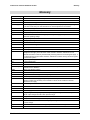
Table of Contents
Table of Contents
1.
2.
Introduction .......................................................................................................................... 1
1.1
Intel® Server Chassis SC5400 Design Features..................................................... 1
1.2
Intel® Server Chassis SC5400BASE Summary ...................................................... 3
1.3
Intel® Server Chassis SC5400BRP Summary ........................................................ 4
1.4
Intel® Server Chassis SC5400LX Summary ........................................................... 4
1.5
Product Matrix.......................................................................................................... 5
Chassis Features.................................................................................................................. 6
2.1
Chassis Dimensions and Weight ............................................................................. 6
2.2
System Colors ......................................................................................................... 6
2.3
Pedestal Front Bezel ............................................................................................... 7
2.4
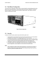
Rack Mount Configuration ....................................................................................... 8
2.5
Security.................................................................................................................... 8
2.6
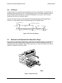
I/O Panel.................................................................................................................. 9
2.7
Standard and Optional Hot Swap Drive Bays .......................................................... 9
2.7.1
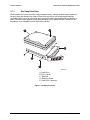
Hot Swap Drive Bays ............................................................................................. 10
2.7.2
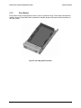
Drive Blanks........................................................................................................... 11
2.8
3.
Front Panel.......................................................................................................................... 13
3.1
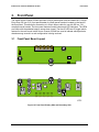
Front Panel Board Layout...................................................................................... 13
3.2
Front Panel Connectors......................................................................................... 14
3.2.1
3.3
4.
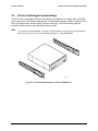
5.25-inch Half-height Peripheral Bays ................................................................... 12
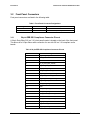
24pin EEB SSI Compliance Connector Pin-out ..................................................... 14
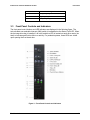
Front Panel Controls and Indicators ...................................................................... 15
3.3.1
Power / Sleep LED ................................................................................................ 17
3.3.2
System Status LED................................................................................................ 17
3.3.3
Drive Activity LED .................................................................................................. 18
3.3.4
System Identification LED...................................................................................... 18
System Cooling .................................................................................................................. 19
4.1
Processor Passive Heat Sink Cooling ................................................................... 19
4.2
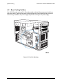
Base Cooling Solution ........................................................................................... 20
4.3
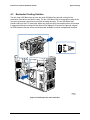
Redundant Cooling Solution .................................................................................. 21
4.4
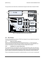
Fan Control ............................................................................................................ 22
Revision: 1.0
iii