1
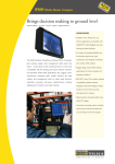
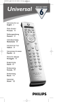
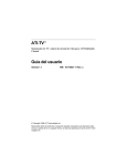
NEC
PX-TUDI-01
OWNER’S MANUAL
BEDIENUNGSANLEITUNG
DIGITAL TERRESTRIAL TV TUNER
V1.1 GW
Regulatory Compliance
CE Mark
This equipment has been tested and found to comply with the European radiation limits. These limits
are designed to provide reasonable protection against harmful interference in a residential installation.
This equipment generates radio frequency energy, and if not installed and used in accordance with the
instructions, it may cause harmful interference to radio communications. However, there is no guarantee
that the interference will not occur in a particular installation.
If this equipment does cause harmful interference to radio or television reception, this can be prevented
by one or more of the following measures:
•
•
•
•
Reorient the receiving antenna
Increase the separation between the equipment and tuner.
Connect the equipment to an outlet on a mains circuit other than the one to which the PX-TUDI01 is connected.
Consult the dealer or an experienced Radio / TV technician for help.
Content
i
Safety First
Please review the following safety precautions. If this is your first time using a PX-TUDI-01 digital
terrestrial tuner, read this manual before installing or using the PX-TUDI-01. If the PX-TUDI-01 is not
functioning properly, please contact your distributor or system installer.
WARNING!
!
RISK OF ELECTRICAL SHOCK
DO NOT OPEN
WARNING:
TO REDUCE THE RISK OF ELECTRICAL SHOCK
DO NOT REMOVE THE COVER
NO USER-SERVICEABLE PARTS ARE INSIDE
REFER SERVICING TO QUALIFIED PERSONNEL
The lightening symbol in a triangle is used to alert you of the presence of dangerous voltage levels
inside the tuner that may be sufficient to constitute a risk of electric shock to anyone opening the
case. It is also used to warn against improper installation or handling of the tuner that could damage
the electrical system in the tuner or any other equipment attached to the PX-TUDI-01.
!
The exclamation mark in a triangle is used to notify you of the important operating and
maintenance instructions. Failure to follow these instructions may cause injury to the person
handling it or damage to the PX-TUDI-01.
Content
ii
Be careful with electricity:
Power Outlet: To prevent electric shock, be sure the electrical plug used on the receiver's power cord is
compatible with the electrical outlet used to supply power to the PX-TUDI-01. Connect the power cord only
to a power source that operates at 100 ~ 240 Volts AC, 50/60 Hz.
Power Plug: A three pin power plug is provided with the receiver. Be sure it is used with a properly
grounded three-wire power socket.
Power Cord: Be sure the power cord is routed so that it will not be stepped on or pinched by heavy items.
Power Overloading: Avoid overloading electrical outlets or extension cords, which could result in an
electric shock or fire.
Natural Calamities: To protect the equipment from natural calamities when the tuner is left unused for a
long period, disconnect it from the power source.
Protect Other Equipment: Unplug the tuner before connecting any other equipment, especially the TV
antenna. Connect all equipment to the receiver before plugging any power cords to the power source.
Power Lines: Be sure your TV antenna is not located near overhead power lines, or where it might fall into
any power lines. Also be careful to avoid touching any such power lines when installing the TV antenna.
Antenna Grounding: Be sure that antenna is grounded to provide protection from lightening and build-up
of static electricity
!
Also follow these precautions:
Ventilation: Do not block the ventilation slots on the PX-TUDI-01, Blocking the airflow may damage the
PX-TUDI-01. Arrange the components so that the air can flow freely around the PX-TUDI-01. Ensure that
there is adequate ventilation if the PX-TUDI-01 is placed in a stand. Put the PX-TUDI-01 in a properly
ventilated area, away from direct sunlight or any source of heat.
Overheating: Avoid placing the PX-TUDI-01 on top of a hot component such as a power amplifier.
Risk of Fire: Do not place the PX-TUDI-01 on top of easily combustible material, such as carpet or fabric.
Proper Connections: Ensure that all cables and equipment are connected to the PX-TUDI-01 as described
in this manual.
Object Entry: To avoid electric shock, never place anything in the slots of the case and never remove the
cover.
Water Exposure: Exposure to mist, rain, etc., may lead to electric shock or fire.
Content
iii
Table of Contents
Chapter 1: Introduction …………………………………………………………
A Brief Look at Terrestrial Television ……………………………………………
What’s in this Guide ………………………………………………………………
Summary of Features ……………………………………………………………...
Menu Tree …………………………………………………………………………
1-1
1-1
1-2
1-3
1-4
Chapter 2: Installation ………………………………………………………….
Introduction ……………………………………………………………………
Package Contents………………………………………………………………
Remote Control…………………………………………………………….
Connection Panel…………………………………………….…………….
RF/Video Cable Types…….………………………………………………
Physical Installation………………………………………………………..
2-1
2-1
2-1
2-2
2-5
2-5
2-6
Chapter 3: Initial Configuration……………………………………………… 3-1
Introduction ……………………………………………………………………... 3-1
Steps for Configuring the Receiver……..……………………………………….. 3-2
Setting Channel…………………………….……………………………………... 3-2
Search Channel…………………………………………………………… 3-3
Auto Scan ………………………………………………..………………. 3-3
Quick Scan /Manual Scan ….……………………………………………. 3-4
Antenna Power ……………….……………………………………………. 3-4
Restore Defaults…….……………………………………………….….. 3-5
General Setting………………………………………………………………..…. 3-5
Menu Language………………………………………………………….. 3-5
Audio Language…………………………………………………………. 3-6
I-Plate Option………….………………………………………………… 3-6
Local Time……………….……………………………………………… 3-6
Audio Output……………….……………………………………………… 3-7
Change Password……………………………………………………….. 3-7
SCART Selection……………………………………………………….
3-7
Video Mute……………………………………………………………..
3-7
Content
iv
Chapter 4: Using The Receiver……………………………………………….
Introduction …………………………………………………………………….
Switching the Receiver On and Off…………………………………………
Using the Menus and Remote Control……………………………………….
Information Plate (I-Plate)………………………………………….…..
Volume Bar………………………………………………………………
Recall Button ………………..…………………………………………
Mute Button……………………………………………………………..
Audio Track Button ………………………………………………..
4-1
4-1
4-1
4-1
4-2
4-2
4-2
4-2
4-3
TV Guide (EPG) …………………….………………………………………..
Selecting Channels……………………………………………………….…..
Using Numeric keys…………………………………………………….
Sort Services…………….……………………………………………………
Parental Guidance……………………………………………………………
Censor Control…………………………………………………………..
Change PIN………………………………………………………………
Signal Quality…………………………………………………………………
IRD Status………………………………………….………………………. ….
4-3
4-3
4-4
4-4
4-7
4-7
4-8
4-9
4-10
Appendix A: Interference With The Receiver..………………………………
Appendix B: Troubleshooting…………………………………………………
Appendix C: Troubleshooting…………………………………………………
Appendix D: Specifications……………………………………………………
A
B
C
D
Content
v
Chapter 1:
Introduction
A Brief Look at Terrestrial Television
Terrestrial broadcast is the traditional way of watching TV programs via a roof top or indoor
antenna. It is commonly known as Analogue TV.
In recent years “Digital Terrestrial TV” has been introduced in several countries. It offers improved
quality via a noise free crisp picture quality and CD like crystal clear sound in addition to a
convenient “EPG” (Electronic Program Guide) and 16:9 video format.
Traditional analogue TV transmissions require one radio frequency channel per TV channel.
Whereas an analog terrestrial video program requires 8MHz bandwidth, a digital terrestrial video
program only requires 1 to 2 MHz bandwidth. In other words, four to eight video programs or
multiple audio and data channels can be transmitted in place of one analog program. The
broadcasters can therefore now increase the number of programs and services they offer with a
minimal increase in cost. Furthermore, since the signals are transmitted in digital format, there is
absolutely no quality loss between transmission and reception as is the case with analog mode.
digital format also allows for transmission of high speed Internet and other data
Digital TV signals are transmitted in Free-to-Air (FTA) mode which can be received by anyone with
an MPEG 2 – DVB compliant digital terrestrial receiver such as the PX-TUDI-01.
The PX-TUDI-01 Tuner is fully MPEG 2 / DVB-T (digital video broadcast-terrestrial) compliant,
delivering crystal-sharp video and excellent sound. It supports a signal range from 51 to 858 MHz,
and can be easily programmed for all the channels within the VHF/UHF frequency spectrum. It can
receive major and sub-channels containing both video and audio programs.
Introduction
1-1
What's in this Guide?
Chapter 1: Introduction
• Describes the key features provided by the PX-TUDI-01 terrestrial TV tuner
• Shows you how to quickly start using the tuner
• Shows the Menu Tree of the PX-TUDI-01
Chapter 2: Installation
• Describes how to install the terrestrial tuner and attach related equipment
• Provides a detailed description of the tuner's connection panel
Chapter 3: Initial Configuration
• Explains how to scan the digital terrestrial TV channels
• Describes how to configure the General settings of the Tuner
Chapter 4: Using The Tuner
• Explains I-plate functions
• How to sort certain channels and use EPG function
• Parental guidance and password control
• How to check signal quality and align the antenna
Appendices:
• Troubleshooting
• Specifications
Introduction
1-2
Summary of Features
The PX-TUDI-01 Terrestrial TV receiver supports digital functions that are fully MPEG 2 – DVB
compliant. It can store up to 2,000 digital channels (1000 audio channels and 1000 video
channels). It can receive Free-to-Air digital programs transmitted from all the available VHF/UHF
bands in your region. Just follow the friendly On-Screen Display (OSD) to guide you through all the
steps necessary to configure your receiver; then begin enjoying all the video and audio channels
with crisp picture quality and the crystal clear sound.
The key features of the tuner are described below:
Connection Panel
The Connection Panel of the tuner includes all connections, Power LED indicator and power switch
button. For more information on the Rear Panel refer to Chapter 2.
Remote Control
The Remote Control can be used to operate all Tuner functions as well as some major functions of
your NEC Plasma Display. For more information on using the Remote Control, refer to Chapter 2
and to the various system operations described in Chapter 3.
System Menus
All the receiver's features can be accessed through the system menus. These menus can be
accessed with simple point and click actions, using the navigation and select buttons on the
remote control. The menus include items such as Transmission parameter Configuration, Channel
List, Electronic Program Guide, Audio Options, and Parental Lock. For more information on using
the menu system, refer to the simple "Menu Tree" described later in this chapter, or refer to the
more detailed menu descriptions in Chapters 3 and 4.
Parental Lock
Channels which are not suitable for viewing by children can be protected by using the password
facility. For more information on how to lock the sensitive channels, refer to "Using Parental
Control" in Chapter 4.
Introduction
1-3
Menu Tree
Main Menu
Sort Services
Parental Guidance
Censor Control
Signal Quality
Change Password
Installation
Channel Setting
Introduction
1-4
Search Channel
Manual Scan
Quick Scan
General Setting
Introduction
Antenna Power
Restore Default
Auto Scan
Language
1-5
I-Plate Option
Menu Language
Local Time
Audio Language
Audio Output
IRD Status
Introduction
1-6
Chapter 2:
Installation
Introduction
Depending on your location you need an indoor or outdoor antenna.
If your service provider or system installer has already set up the outdoor antenna and connected
the tuner, then you can skip to the operations specified in Chapter 4. However, if you are setting up
the system by yourself, please read through this section and be sure you follow all of the
precautions listed under "Safety First".
Note: Installation procedures for antenna and related system equipment are not covered in this
manual.
Package Contents
Unpack the tuner and verify that all of the items listed below are included. Should the receiver be
sent for troubleshooting or upgrading, it must be enclosed in the same case. Examine all the items
to ensure that nothing has been damaged during shipment. If any of the items are damaged, then
contact your service provider or local distributor before continuing with installation.
•
•
•
•
•
•
•
PX-TUDI-01 Terrestrial TV Tuner
Bracket
Remote Control (with 2 AAA batteries)
SCART to Audio (RCA) / S-Video adapter cable
Y- shaped Power Cable
IR Sensor
User Manual
Installation
2 -1
Remote Control
The Remote Control provides easy access to all of the receiver's functions, including selecting
channels and using the menus. It emits infrared signals and should be operated at a distance of
three to four meters from the receiver. When using the Remote Control, ensure a direct line of
sight to the receiver.
The batteries for the Remote Control are packaged separately. Before you start using the receiver,
please install these batteries according to the figure shown here:
Be sure to install the battery +/- position correctly.
Note: To avoid damaging the remote control, discard any depleted or old batteries.
The buttons on the remote control are described in the following table.
Installation
2 -2
IR Remote Control- Tuner related functions (after pressing “Tuner” key)
1.
2.
3.
4.
5.
6.
7.
8.
9.
10.
11.
12.
13.
14.
15.
16.
17.
On: Press to switch ON the display as
well as tuner box.
OFF: Press to switch OFF the display as
well as tuner box
Wide: This button only controls the
display.
0 ~ 9 Number Keys: Numeric Keypad for
entering numbers.
Tuner: Press to active Tuner mode on the
remote control
Display: Press to active Display mode on
the remote control.
Exit: goes to the previous menu or exits
the menu when in the main menu, or exits
from the EPG, and information screens.
Menu: displays the main menu on the
screen (installation menus, etc.).
Guide: displays the EPG (Electronic
Program Guide).
Recall: Switches the Receiver to the
previously selected channel.
Cursor buttons: moves the cursor or field
to select items or adjust function. In TTX
mode you can move page up or down.
OK: Selects highlighted options or values
in the menus and will open the Radio or
TV List when no display is shown.
Vol+ / Vol-: Adjust the volume
CH+ / CH-: Select channels up or down or
pages up or down when in TV list.
Audio Track: Selects audio tracks,
provided more than one audio track is
available for that particular channel.
Radio/ TV: Switch between TV and Radio
services.
Information: displays the program
information bar (I-Plate) on the screen.
When pressed twice the Receiver displays
the Extended Program Information.
Mute: Audio mute.
Favorite Channel List One or Red Fastest
18.
19. Red Key (Favorite channel list 1): Call out
page in TTX mode
20. Green Key (Favorite channel list 2): Call up Favorite Channel List Two or Green
Fasttext page in TTX mode.
21. Yellow Key (Aspect Ration): Adjust the aspect ratio or call up Yellow Fasttext Page in
TTX mode.
22. Blue Key: Call up Blue Fasttext Page in TTX mode.
23. Teletext: Start Teletext.
Installation
2 -3
IR Remote Control- Monitor Display related functions (after pressing “Display” key)
1.
2.
3.
4.
5.
6.
7.
8.
11.
12.
13.
14.
16.
17.
18.
19.
20.
21.
22.
On: Press to switch ON the display as
well as tuner box.
OFF: Press to switch OFF the display as
well as tuner box
Wide: Press to toggle screen size.
0 ~ 9 Number Keys: Used to select
sources and picture adjustment set-ups of
your Display.
Video: Select Video input source
DVD/HD: Select HD input source
RGB/PC: Select RGB input source
Contrast +/-: Adjust contrast of picture.
Brightness +/-: Adjust brightness of
picture.
Colour +/-: Adjust the colour of picture.
Auto Adjust: Automatic adjustment of
picture quality.
Tuner: Press to active Tuner mode on the
remote control
Display: Press to active Display mode on
the remote control.
Exit: Exit the current menu selection and
return to the previous menu. Press this
button repeatedly to close all menus.
Menu: Select the main OSD (On Screen
Display) menu.
Cursor buttons: Use left/ right keys to
select item or adjust function; use up/
down keys to select desired item on menu.
OK: Confirm the highlighted item in menu.
Vol+ / Vol-: Adjust the volume.
CH+ / CH-: Select channels up or down or
earlier or next page when in TV list.
Radio/ TV: Switch between TV and Radio
services.
Information: Displays the program
information bar (I-Plate) on the screen.
When pressed twice the tuner displays the
Extended Program Information.
Mute: Audio mute.
Side: (will not work with all NEC monitors)
Single: (will not work with all NEC monitors)
PIP: (will not work with all NEC monitors)
Select: (will not work with all NEC monitors)
Installation
2 -4
Connection Panel
The connection panel is equipped with connectors for attaching antenna and NEC Plasma Display.
.
A
B
C
D
E
F
G
H
I
A. TV SCART
Connects the SCART output on PX-TUDI-01 and S-Video, Audio L/R input of your NEC Plasma Display
for both audio and video output.
B. Composite Video, Audio L/R
Can be used for e.g. recording.
C. Coaxial SPDIF Output
Digital Audio Output: Connect to your Audio amplifier’s Coaxial SPDIF input
D. RS-232
A 115kbit/s RS232 serial port suitable for connection to a PC, usually for software upgrade and data
output
E. RF IN
Connects the VHF/UHF antenna. This connector accepts input signals ranging from 51 to 858 MHz
RF OUT is looped through from RF IN and can be used to connect a second receiver.
F. LED Power Indication
Red= Stand-by. Green = On
G. Infrared Sensor Connector
Connect the IR sensor cable to PX-TUDI-01 and mount sensor on display (see quick install manual)
H. 230 V AC
Connect the attached Y- shaped Power Cable.
I. Power Switch
RF/Video Cable Types
Audio/Video (RCA) connector and cables – These cables are commonly
grouped with three connectors on both ends, and are color coded as yellow –
video signal, white – left signal, and red – right audio signal.
SCART connector and cable – delivers both video and audio signals to your
Display. It combines the same excellent picture quality as S-Video and stereo
sound, all in a single cable.
Installation
2 -5
Physical Installation
Connecting to IR Sensor
n
o
q
p
r
Connecting to Y- Shaped Power Cable
n Connecting to NEC Plasma
Display with SCART/ S-Video, Audio LR cable
Connecting the PX-TUDI-01’s “PLASMA” SCART connector to your NEC display’s SVideo
and Audio L/R Input
o Connecting to the Dolby Digital Amplifier
Connecting the PX-TUDI-01’s S/PDIF with a Dolby Digital Amplifier using a coaxial cable.
p Connecting to antenna
Connecting the PX-TUDI-01’s RF.IN with antenna
q Connecting to Infrared Sensor
Connecting the IR sensor to PX-TUDI-01
r Connecting Y-Shaped Power Cable to PX-TUDI-01
Installation
2 -6
Chapter 3:
Initial Configuration
Introduction
After finishing the Hardware Installation as described in Chapter 2, switch on the receiver. The
Welcome Banner will be displayed together with an instruction to press the MENU key on the
Remote Control.
With the help of the Beeper function in the “SIGNAL QUALITY” menu, it is possible to adjust the
antenna to receive the strongest possible signal in your area (see Chapter 4). In case an active
antenna is used it can be powered by the tuner box (see “Antenna Power” in this chapter).
The following Menu will be displayed after pressing the MENU key
● Initial Screen –
Pressing the TUNER key followed by the MENU
key on the remote control will take you to the main
menu of OSD
(On Screen Display)
● The key functions of each item on the main
menu are shown as below,
Menu
SORT SERVICE
PARENTAL GUIDANCE
SIGNAL QUALITY
INSTALLATION
IRD STATUS
Description
Displays all of the available TV channels in separate Main List and
selected channels in the Favorites List, similarly for Radio channels
also.
Used for locking certain channels according to the age limits.
Provides detailed information about the Selected Channel and its Signal
Strength.
Used for searching terrestrial TV signals and configuring the
transmission parameters.
Indicates the latest Version of the PX-TUDI-01’s software
Note: Use the MENU key on the Remote Control to open the Main Menu, and the Arrow keys to
move through the menus, the OK key to select specific items, and EXIT key to return to the
previous menu.
Initial Configuration
3-1
Steps for configuring the Tuner
● Press the TUNER key of remote control. Then, press
the MENU key to display the Main Menu.
● Using the Up / Down keys, select the INSTALLATION
option
Channel Setting
●
Upon selecting the Channel Setting option from the
Installation menu, the following menu will be displayed.
•
The CHANNEL SETTING menu has the following options.
1. Search Channel
2. Antenna Power
3. Restore Default
Initial Configuration
3-2
Search Channel
Under Search Channel menu, there are three options
• Manual Scan
• Quick Scan
• Auto Scan
Auto Scan
In this mode all pre-stored channels in the list are scanned.
This option should be used if you don’t know which TV channels are used in your area.
● Upon selecting the “AUTO SCAN” menu, the following
submenu will be displayed.
● Upon pressing the green key on the remote control,
the scanning process will begin and the Scan
Screen displayed.
● Scanning all channels will take about 1 to 3 minutes.
The progress of the scanning process will be indicated
along with any channels detected.
Initial Configuration
3-3
Quick Scan
This option should be used if you know which TV channels are used in your area.
● Upon selecting the “QUICK SCAN” menu, the following
submenu will be displayed.
● Please use up and down keys and select with the yellow key
the channels that are used in your area.
Start scan of the selected channels by pressing the green
key on your remote control.
It’ll take about 1 minute to complete this process.
Manual Scan
This option should be used if you want to scan a new channel from the pre-stored list or you want
to scan a channel which is not present in the pre-stored list.
Newly detected services will be added to those already stored.
● Upon selecting the “MANUAL SCAN” menu, the following
submenu will be displayed.
-1- Press “OK” key to activate the “Channel” mode (background
of channel number will change from yellow to red).
-2- Use L/R Arrow keys to go to desired channel number or
use numeric keys.
-3- Press “OK” to confirm.
-4- Press green key to start scan of the selected channel.
-5- The newly detected services will be added to the already
stored services.
Note: The Channel number and Frequency are according to
European CCIR standard. It is possible to change the
Frequency of the selected Channel in this menu
but this Frequency change will also be copied into the
pre-stored table.
Antenna Power
In case an active antenna is used it can be powered (+ 5 Volt DC via the coax cable) by the PXTUDI-01. The default value is “ANTENNA POWER ON” NO
To activate this option, go to the ANTENNA POWER Menu and change “ANTENNA POWER ON”
with L/R key to “YES” (confirm Warning message with “OK”).
Initial Configuration
3-4
Restore Defaults
Select the option ‘Restore Defaults’ to reset the IRD (Receiver) to the original factory settings.
Please take careful note:
•
•
On selecting this option, a warning message appears saying that all your currently
saved settings will be lost.
If you wish to go ahead nonetheless, press OK to get the initial settings provided by the
Manufacturer.
General Settings
During Initial Configuration you must configure the following General Settings of the receiver:
●
On selecting the General Setting option from the
Installation menu, the submenu will be displayed :
1. LANGUAGE
2. I-PLATE OPTION
3. LOCAL TIME
4. AUDIO OUTPUT
● You can configure the receiver for the required
language, and control the display and duration of the
information banner (I-Plate). You can set the time of
the receiver according to your local time.
Menu Language
● On selecting this option from the above menu, you can
change the menu language (OSD) of the tuner.
● Use Up/Down Arrow keys to select the desired
language and confirm with “OK”.
Note: After selecting a language from the menu, all
the menus in the OSD will change according to the
language you selected
Initial Configuration
3-5
Audio Language
● On selecting this option from the above menu, you
can
change the
ALTERNATIVE
audio channel.
language
of
the
MAIN
and
Note: The audio language you select will only work when the
broadcasting signal carries that language sound track
I-Plate Option
● On selecting this option from the above menu, you can
change the I-PLATE configuration.
● With the Left /Right Arrow keys you can select the
duration of the display staying on screen of between 0
and 20 seconds.
● On selecting DISPLAY ON CHANNEL CHANGE option,
you can press Left / Right arrow keys to select YES
when you want to show I-Plate during channel change,
select NO when you don’t want to show I-Plate during
channel change
Local Time
● You can use the “Local Time” option to set the time in
the Receiver. On selecting this option, you can set
the time by changing the offset value.
Note: You can change the time with the Left / Right Arrow
keys. To activate the changed time, press OK key.
If you do not want to make a change, press EXIT
key to return to the General Setting Menu.
Initial Configuration
3-6
Audio Output
The default Audio mode is Analogue Audio.
In case the Digital SPDIF Output is used, the Audio Output format should be changed to “AC-3” or
“PCM” (depending on the received signal and your Audio Amplifier).
Note: In most cases there will not be an analogue Audio Output signal if one of the Digital modes is
selected.
Go to Audio Output Menu and change setting with L/R key and confirm with “OK” key .
EXIT key to return to the previous menu.
Initial Configuration
3-7
Appendix A: Interference With The Receiver
Weather Induced Signal Fading
Natural calamities may affect signal reception. If the terrestrial TV programming is severely
affected by inclement weather conditions, there are a few basic steps you can take to improve
reception:
1. Be sure your antenna is aimed to receive the strongest possible signal.
2. If this does not solve the problem, you may consider installing a larger antenna with higher
gain. This can help to gather more of the signal transmitted from the TV station.
3. If you live in an area subject to frequent snow or freezing rain, you may need to install a deicing
system to eliminate the accumulation of unwanted ice, snow or moisture from the surface of
your antenna.
4. If the program reception is adversely affected by heavy winds, you can stabilize the antenna
mount with cables.
Home Appliances’ Interference
When you turn on home appliances like air conditioner and washing machine while you are using
PX-TUDI-01, in a very few cases the power surge caused by turning on these home appliances will
interfere PX-TUDI-01’s performance.
If this happens we suggest you to use a different AC power source (different AC outlet) between
PX-TUDI-01 and other home appliances.
Appendix
A
Appendix B: Troubleshooting
If you encounter any problems with the PX-TUDI-01, look through this section for a description of
your problem. Try solving the problem by following the given solutions. However, if after attempting
all the recommended actions you still cannot solve the problem, please contact your local service
provider or system installer for assistance.
Problem
Solution
(1) The PX-TUDI-01 rear panel power (a) Check the Y-shaped power cable and make sure the power plug
indicator doesn't light up.
is well plugged into a stable power outlet.
(b) Check if "Power switch" button on the rear panel of PX-TUDI-01
is switched to “ON”.
(2) No picture on your display
(a) Make sure the connection between PX-TUDI-01 and your NEC
display matches the mode your NEC display should be set to.
For instance, if you use PX-TUDI-01’s SCART output to
connect your NEC display’s S-Video input and Audio L/R input
you must choose external S-video input mode in NEC display.
(b) Press the “Tuner” button on the remote control. Then press
"Menu" button on the remote control to call up the On Screen
Display. If the tuner menu appears, the connections between
tuner and display are OK and it seems the problem is caused
by an incorrect incoming antenna signal.
(3) Poor picture quality
(a) Check the antenna and make sure it is aligned to the correct
direction. Use the Signal Quality option in OSD menu to check
the signal's BER and RF Level when aligning the antenna.
(b) If you use any kind of amplifier to boost the signal level, please
check whether it works well, and ask help from the antenna
installer.
(4) No audio service
(a) Check the volume is properly set and not in "Mute" mode.
(b) Check the audio connectors.
(c) Check in the NEC Plasma Menu if the used audio input is linked
with the S-Video Input.
(d) Check in the Tuner Audio Output Menu if the correct output
mode is selected. with the local TV stations. Sometimes they
are just testing new services on their TV or Radio channels.
(e) Press CH+ or CH- button (may be the actual channel is
scrambled or out of order)
Appendix
B
Appendix C: Troubleshooting
Problem
Solution
(5) Does not have all the
(a) Try "Auto Scan" to scan all the channels again.
channels available after using
(all previously stored channels will be deleted).
“Quick Scan”
(b) If you still cannot get some channels please use "Manual Scan”.
(6) Does not have all the
(a) Try "Manual Installation" to scan these missing channels.
available channels after using
"Auto Scan”
(7) Cannot lock signal by using (a) Check in the Manual Scan menu if the frequency of the selected
"Manual Scan"
channel (displayed below the channel number) is exactly same as the
frequency used in your local area.
If not, change the frequency in this menu accordingly.
(8) Cannot receive all channels
after moving the receiver to
another city
Appendix
(a) In the new area different channels are used.
-you can add the new channels in the “Manual Scan” menu.
- apply a new “Auto Scan or “Quick Scan”
(all previously stored channels will be deleted)
C
Appendix D: Specifications
TUNER
Frequency Range
Input Signal Level
Bandwidth
DEMODULATOR
Type
Inner Code Rate
FFT Modus
Constellation
Guard Interval
VIDEO
Outputs
Aspect Ratio
Resolution
AUDIO
Decompression
Sampling Frequency
Analogue Output
Connectors
TELETEXT DECODER
Fasttext
MEMORY
RAM
Flash
Non-Volatile Memory
CONNECTORS
Tuner Input (from Digital Antenna)
Tuner Loop Output
Composite Video Output
Audio Output
SCART Output
SPDIF
RS232
IR Input (Infrared Input)
Power Input
GENERAL
Input Voltage
Power Consumption
Dimensions (WxHxD)
Weight
Operating Temperature
Appendix
51 to 858 MHz
32 –82dBµV
8MHz
COFDM
DVB specified FEC Code Rates (1/2, 2/3, 3/4, 5/6, 7/8 )
2K,8K
QPSK , 16QAM , 64 QAM
1/4,1/8,1/16,1/32
PAL Composite + S-VIDEO (Y/C) from SCART
4:3 or 16:9
720x576i
MPEG-I Layer I and II, Musicam
32 KHz, 44.1KHz and 48.0 KHz
Mono / Stereo / Dual
Digital: SPDIF (Coaxial)
Analogue: RCA L/R + SCART L/R
4 pages
6 Mbytes
2 Mbytes
8 Kbytes
IEC female
IEC male
RCA
RCA (L/R)
S-Video + Audio L/R
RCA
9 Pin D- sub male (for Software Update)
Mini Jack
3 pin, male (IEC 320)
100~264 VAC 50/60 Hz
< 15 W
280 x 150 x 35 mm
1,5 kg (without packing) / 3,0 kg with packing
5°C -45°C
D
Supplied Accessories
1 x Y- Power Cable (Plasma + Tuner on one cable)
1 x SCART Adapter Cable (Scart to S-Video + Audio L/R)
1 x Dual Function Remote Control
1 x IR Sensor with cable
* The specifications can be changed at any time without pre-advice
Appendix
E