1
INSTALLATION AND USER’S GUIDE
ADAPTEC SERIAL ATA RAID 2410SA
Adaptec Serial ATA RAID 2410SA
Installation and User’s Guide
R
Copyright
©2003 Adaptec, Inc. All rights reserved. No part of this publication may be
reproduced, stored in a retrieval system, or transmitted in any form or by any
means, electronic, mechanical, photocopying, recording or otherwise, without the
prior written consent of Adaptec, Inc., 691 South Milpitas Blvd., Milpitas, CA 95035.
Trademarks
Adaptec, the Adaptec logo, and Adaptec Storage Manager are trademarks of
Adaptec, Inc., which may be registered in some jurisdictions.
Windows 2000 and Windows XP are trademarks of Microsoft Corporation in the US
and other countries, used under license.
All other trademarks are the property of their respective owners.
Changes
The material in this document is for information only and is subject to change
without notice. While reasonable efforts have been made in the preparation of this
document to assure its accuracy, Adaptec, Inc. assumes no liability resulting from
errors or omissions in this document, or from the use of the information contained
herein.
Adaptec reserves the right to make changes in the product design without
reservation and without notification to its users.
Disclaimer
IF THIS PRODUCT DIRECTS YOU TO COPY MATERIALS, YOU MUST HAVE
PERMISSION FROM THE COPYRIGHT OWNER OF THE MATERIALS TO AVOID
VIOLATING THE LAW WHICH COULD RESULT IN DAMAGES OR OTHER
REMEDIES.
ii
Adaptec Customer Support
If you have questions about installing or using your Adaptec product, check this
document first—you will find answers to most of your questions here. If you need
further assistance, use the support options listed below.
Technical Support Identification (TSID) Number
■
Before contacting Technical Support, you need your unique 12-digit TSID
number. The TSID number identifies your product and support status.
■
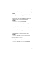
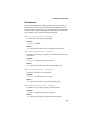
The TSID number is included on two white, bar-coded labels, like the example
below.
■
If you register by mail, affix one copy of the TSID label to the registration card,
which may be contained on the CD. Also affix a copy of the TSID label to the CD
jacket so that you don’t lose it.
Support Options
■
Search the Adaptec Support Knowledgebase (ASK) at ask.adaptec.com for
articles, troubleshooting tips, and frequently asked questions for your product.
■
For support via Email, submit your question to Adaptec’s Technical Support
Specialists at ask.adaptec.com.
North America
■
Visit our Web site at www.adaptec.com.
■
For information about Adaptec’s support options, call +1 408-957-2550,
24 hours per day, 7 days per week. To speak with a Technical Support Specialist,
■
For Hardware products call +1 408-934-7274,
Monday to Friday, 3:00 A.M. to 5:00 P.M., Pacific Time.
■
For RAID and Fibre Channel products call +1 321-207-2000 ,
Monday to Friday, 3:00 A.M. to 5:00 P.M., Pacific Time.
To expedite your service, have your computer in front of you.
■
To order Adaptec products, including accessories and cables, call +1 408-957-7274.
Or, you can order cables online at www.adaptec.com/buy-cables.
iii
Europe
■
Visit our Web site at www.adaptec-europe.com.
■
German: To speak with a Technical Support Specialist, call +49 89 43 66 55 22,
Monday to Friday, 9:00 to 17:00, CET. For support via e-mail, submit your
question to Adaptec’s Technical Support Specialists at ask-de.adaptec.com.
■
French: To speak with a Technical Support Specialist, call +49 89 43 66 55 33,
Monday to Friday, 9:00 to 17:00, CET. For support via e-mail, submit your
question to Adaptec’s Technical Support Specialists at ask-fr.adaptec.com.
■
English: To speak with a Technical Support Specialist, call +49 89 43 66 55 44,
Monday to Friday, 9:00 to 17:00, GMT. For support via e-mail, submit your
question to Adaptec’s Technical Support Specialists at ask.adaptec.com.
■
You can order Adaptec cables online at www.adaptec.com/buy-cables.
Japan
■
Visit our Web site at www.adaptec.co.jp.
■
To speak with a Technical Support Specialist, call +81 3 5308 6120
Monday–Friday, 9:00 A.M. to 12:00 P.M and 1:00 P.M. to 6:00 P.M.
iv
Limited 3-Year Hardware Warranty
1.
Adaptec, Inc. (“Adaptec”) warrants to the purchaser of this product that it will be free from
defects in material and workmanship for a period of three (3) years from the date of
purchase. If the product should become defective within the warranty period, Adaptec, at
its option, will repair or replace the product, or refund the purchaser’s purchase price for the
product, provided it is delivered at the purchaser’s expense to an authorized Adaptec
service facility or to Adaptec.
2.
Repair or replacement parts or products will be furnished on an exchange basis and will
either be new or reconditioned. All replaced parts or products shall become the property of
Adaptec. This warranty shall not apply if the product has been damaged by accident,
misuse, abuse or as a result of unauthorized service or parts.
3.
Warranty service is available to the purchaser by delivering the product during the warranty
period to an authorized Adaptec service facility or to Adaptec and providing proof of
purchase price and date. The purchaser shall bear all shipping, packing and insurance costs
and all other costs, excluding labor and parts, necessary to effectuate repair, replacement or
refund under this warranty.
4.
For more information on how to obtain warranty service, write or telephone Adaptec at 691
South Milpitas Boulevard, Milpitas, CA 95035, (800) 959-7274.
5.
THIS LIMITED WARRANTY DOES NOT EXTEND TO ANY PRODUCT WHICH HAS
BEEN DAMAGED AS A RESULT OF ACCIDENT, MISUSE, ABUSE, OR AS A RESULT OF
UNAUTHORIZED SERVICE OR PARTS.
6.
THIS WARRANTY IS IN LIEU OF ALL OTHER EXPRESS WARRANTIES WHICH NOW
OR HEREAFTER MIGHT OTHERWISE ARISE RESPECT TO THIS PRODUCT. IMPLIED
WARRANTIES, INCLUDING THOSE OF MERCHANTABILITY, FITNESS FOR A
PARTICULAR PURPOSE AND NON-INFRINGEMENT SHALL (A) HAVE NO GREATER
DURATION THAN 3 YEARS FROM THE DATE OF PURCHASE, (B) TERMINATE
AUTOMATICALLY AT THE EXPIRATION OF SUCH PERIOD AND (C) TO THE EXTENT
PERMITTED BY LAW BE EXCLUDED. IN THE EVENT THIS PRODUCT BECOMES
DEFECTIVE DURING THE WARRANTY PERIOD, THE PURCHASER’S EXCLUSIVE
REMEDY SHALL BE REPAIR, REPLACEMENT OR REFUND AS PROVIDED ABOVE.
INCIDENTAL OR CONSEQUENTIAL DAMAGES, INCLUDING WITHOUT LIMITATION
LOSS OF DATA, ARISING FROM BREACH OF ANY EXPRESS OR IMPLIED WARRANTY
ARE NOT THE RESPONSIBILITY OF ADAPTEC AND, TO THE EXTENT PERMITTED BY
LAW, ARE HEREBY EXCLUDED BOTH FOR PROPERTY DAMAGE, AND TO THE
EXTENT NOT UNCONSCIONABLE, FOR PERSONAL INJURY DAMAGE.
7.
SOME STATES DO NOT ALLOW THE EXCLUSION OR LIMITATION OF INCIDENTAL
OR CONSEQUENTIAL DAMAGES FOR CONSUMER PRODUCTS, AND SOME STATES
DO NOT ALLOW LIMITATIONS ON HOW LONG AN IMPLIED WARRANTY LASTS, SO
THE ABOVE LIMITATION OR EXCLUSIONS MAY NOT APPLY TO YOU.
8.
This warranty gives you specific legal rights, and you may also have other rights which vary
from state to state.
v
Regulatory Compliance Statements
Federal Communications Commission Radio Frequency Interference Statement
WARNING: Changes or modifications to this unit not expressly approved by the party
responsible for compliance could void the user’s authority to operate the equipment.
This equipment has been tested and found to comply with the limits for a Class B digital device,
pursuant to Part 15 of the FCC rules. These limits are designed to provide reasonable protection
against harmful interference in a residential installation. This equipment generates, uses, and
can radiate radio frequency energy, and if not installed and used in accordance with the
instruction manual, may cause harmful interference to radio communications. However, there is
no guarantee that interference will not occur in a particular installation. However, if this
equipment does cause interference to radio or television equipment reception, which can be
determined by turning the equipment off and on, the user is encouraged to try to correct the
interference by one or more of the following measures:
■ Reorient or relocate the receiving antenna.
■ Increase the separation between equipment and receiver.
■ Connect the equipment to an outlet on a circuit different from that to which the receiver is
connected.
■ Consult the dealer or an experienced radio/television technician for help.
■ Use a shielded and properly grounded I/O cable and power cable to ensure compliance of
this unit to the specified limits of the rules.
This device complies with part 15 of the FCC rules. Operation is subject to the following two
conditions: (1) this device may not cause harmful interference and (2) this device must accept
any interference received, including interference that may cause undesired operation.
Adaptec, Inc.
AAR-2410SA
Tested to Comply
With FCC Standards
FOR HOME OR OFFICE USE
European Union Compliance Statement
This Information Technology Equipment has been tested and found to comply with
EMC Directive 89/336/EEC, as amended by 92/31/EEC and 93/68/EEC, in
accordance with:
n EN55022 (1998) Emissions
n EN55024 (1998) Immunity:
– EN61000-4-2 (1998) Electrostatic discharge: ±4 kV contact, ±8 kV air
– EN61000-4-3 (1998) Radiated immunity
– EN61000-4-4 (1995) Electrical fast transients/burst: ±1 kV AC, ±0.5 kV I/O
– EN61000-4-5 (1995) Surges ±1 kV differential mode, ±2 kV common mode
– EN61000-4-6 (1996) Conducted immunity: 3 V
– EN61000-4-11 (1994) Supply dips and variation: 30% and 100%
In addition, all equipment requiring U.L. listing has been found to comply with EMC
Directive 73/23/EEC as amended by 93/68/EEC in accordance with EN60950 with
amendments A1, A2, A3, A4, A11.
Australian/New Zealand Compliance Statement
This device has been tested and found to comply with the limits for a Class B digital
device, pursuant to the Australian/New Zealand standard AS/NZS 3548 set out by
the Spectrum Management Agency.
vi
Canadian Compliance Statement
This Class B digital apparatus meets all requirements of the Canadian InterferenceCausing Equipment Regulations.
Cet appareil numérique de la classe B respecte toutes les exigences du Règlement sur
le matériel brouilleur du Canada.
Japanese Compliance (Voluntary Control Council Initiative)
This equipment complies to class B Information Technology equipment based on
VCCI (Voluntary Control Council for Interface). This equipment is designed for home
use but it may causes radio frequency interference problem if used too near to a
television or radio. Please handle it correctly per this documentation.
vii
Contents
1
Introduction
Read this First 1-1
System Requirements 1-2
Operating System Compatibility 1-2
Storage Requirements 1-2
Motherboard Compatibility 1-2
Device Compatibility 1-2
Kit Contents 1-3
Adaptec 2410SA Controller 1-3
About the Documentation 1-4
Installing the Adobe Acrobat Reader 1-4
Controller Features 1-5
Adaptec’s Advanced RAID Technology Features
Array Migration 1-6
Drive Enclosures 1-6
Hot Spares 1-6
Automatic Failover 1-7
Overview of the Installation Process 1-7
Storage Management Software Overview 1-8
Safety Information 1-9
Notes and Cautions 1-9
Electrostatic Discharge 1-9
2
Installing the Controller
Overview 2-1
Installing the Controller 2-2
Checking Your Controller and Devices
Determining the Boot Controller 2-3
3
1-5
2-3
Installing the Driver
Creating the Driver Disk 3-2
Creating the Linux Driver Disk 3-2
viii
Contents
Windows 3-3
Installing the Driver in a New System 3-3
Adding the Driver to an Existing System 3-4
Linux 3-5
Installing the Driver in a New Red Hat System
Adding the Driver to an Existing System 3-6
UnixWare and OpenUNIX 3-7
Installing the Driver on a New System 3-7
Adding the Driver to an Existing System 3-7
4
3-5
Installing Adaptec Storage Manager – Browser Edition
Overview 4-1
Supported Browsers 4-2
Typical, Custom, and Compact Installations 4-2
Remote and Managed Systems 4-3
Installing Adaptec Storage Manager on Windows 4-4
Configuring Internet Browsers on Windows 4-5
Installing Adaptec Storage Manager on Linux 4-8
Installing Adaptec Storage Manager on UNIX 4-9
5
Using Adaptec Storage Manager – Browser Edition
Overview 5-2
Architecture Overview 5-3
Logging In 5-4
Installing a Security Certificate 5-6
Registering Your Software 5-6
The Basics 5-7
Pop-Up Tool Tips 5-8
Physical Devices 5-8
Logical Devices 5-10
A
Adaptec RAID Configuration Utility
Using the Array Configuration Utility A-2
Managing Arrays A-2
Creating Arrays A-6
Initializing Disk Drives A-8
Rescanning Disk Drives A-9
ix
Contents
Using SATASelect A-9
Using the Disk Utilities A-11
Viewing the Event Log A-12
B
DOS Utilities
Using the Adaptec Flash Utility (AFU) B-1
Overview of the AFU B-2
System Requirements B-2
Firmware Floppy Disk Kit B-3
Running the AFU B-4
Accessing the AFU from the GUI B-4
Accessing the AFU from the Command Line B-4
Flashing the Firmware Using AFU B-5
AFU Commands B-7
AFU Error Handling B-10
Using the Array Configuration Utility (ACU) B-11
Interactive Versus Script Mode B-11
Running the ACU B-12
Using Interactive Mode B-12
Creating an Array with ACU B-12
Managing Arrays B-15
Using the Scripting Features B-18
Script File Syntax B-24
Array Definition Block Properties B-25
Error Handling B-32
Playback and Record Notes B-34
Invoking the ACU and Using a Script B-34
C
Command Line Interface (CLI)
Introduction C-1
Terminology C-2
Accessing the CLI C-2
Accessing the CLI in MS-DOS C-3
Accessing the CLI in Windows C-3
Accessing the CLI in UNIX C-3
x
Contents
Using the CLI C-3
Opening and Closing a Controller C-4
Managing Failover Options and Hot Spares
Displaying Controller Information C-9
Displaying Disk Information C-11
Displaying Array Information C-12
CLI Command Dictionary C-15
General Control Commands C-15
Container (Array) Commands C-16
Controller Commands C-25
Disk Commands C-28
Logfile Commands C-32
Task Commands C-33
Enclosure Commands C-34
Using Automated Command Scripts C-38
D
C-7
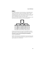
Supported RAID Types
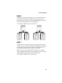
RAID 0 D-2
RAID 1 D-2
RAID 5 D-3
RAID 10 D-4
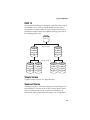
Simple Volume D-4
Spanned Volume D-4
E
Specifications
Glossary
xi
1
Introduction
In this Chapter...
Read this First
1-1
System Requirements
1-2
Kit Contents
1-3
About the Documentation
1-4
Controller Features
1-5
Overview of the Installation Process
1-7
Storage Management Software Overview
1-8
Safety Information
1-9
Read this First
Read this chapter before you begin installing your new Adaptec
Serial ATA RAID 2410SA controller. This is a guide to the rest of the
document, providing a summary of the installation process.
1-1
Introduction
System Requirements
The following system requirements are presented:
■
Operating system compatibility
■
Storage requirements for drivers and software
■
Motherboard compatibility.
■
Device compatibility (for Serial ATA)
Operating System Compatibility
■
Microsoft Windows® 2000, Windows XP®, Windows Server 2003
■
Linux
■
Red Hat 7.3 and 8.0
■
SuSE 8.0 and 8.1
■
UnixWare 7.1.1 and OpenUNIX 8
Note: For the latest Linux compatibility information, visit
www..adaptec.com.
Storage Requirements
Device drivers and storage management software require
approximately 20 MB of disk space.
Motherboard Compatibility
The controller can be installed in a universal PCI slot and requires a
motherboard and BIOS that:
■
Complies with the PCI Local Bus Specification, Revision 2.2.
■
Provides large memory-mapped address ranges.
Device Compatibility
The Adaptec 2410SA controller supports up to four hard drives
(Serial ATA only), using four Serial ATA cables supplied in this kit.
1-2
Introduction
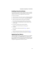
Kit Contents
Your Adaptec controller kit includes:
■
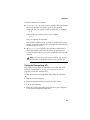
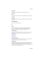
Adaptec 2410SA controller (shown below)
■
Adaptec Serial ATA RAID 2410SA Quick Installation Guide
■
Installation CD
■
Low-profile bracket (in addition to the standard full-height bracket
attached to the controller)
■
Four Serial ATA interface cables
■
Technical Support ID (TSID) label (See page iii for details.)
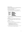
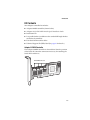
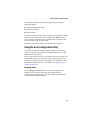
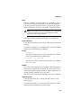
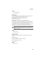
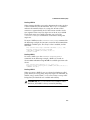
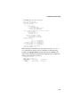
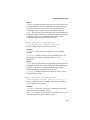
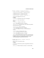
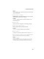
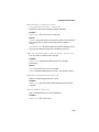
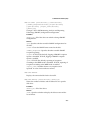
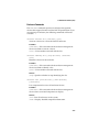
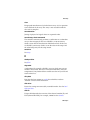
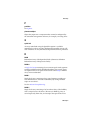
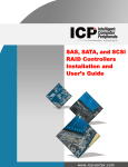
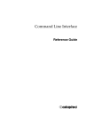
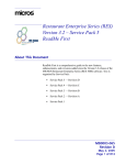
Adaptec 2410SA Controller
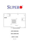
The Adaptec 2410SA controller is shown below. Note the position
of the Serial ATA interface connectors necessary for attaching the
Serial ATA hard drives.
Serial ATA Connectors
1-3
Introduction
About the Documentation
The documentation set for this kit includes:
■
Adaptec Serial ATA RAID 2410SA Quick Installation Guide—This
printed guide contains the essential information for installing
the controller in most situations.
■
Adaptec Serial ATA RAID 2410SA Installation and User’s Guide (this
guide)
■
Adaptec Serial ATA RAID 2410SA Command Line Interface Software
Reference Guide—Provides detailed descriptions of the
command line driven RAID management utility.
■
Release Notes—Before beginning your installation, review the
release notes associated with the Adaptec 2410SA controller,
software, and documentation. To read this information, select
Release Notes from the View Documentation list or open the
Readme file in the root directory of the CD using a text editor. For
the latest updates, visit www.adaptec.com.
These documents are also available at www.adaptec.com. The
documents available from the Web site may be more recent
versions than those on the CD. Check the revision letter on the back
cover of the guide.
Installing the Adobe Acrobat Reader
The Adaptec installation CD contains Windows and Linux versions
of Adobe Acrobat Reader. (You can also download the Reader free
at www.adobe.com.) You need the Reader to view Portable
Document Format (PDF) documents such as the Adaptec Serial ATA
RAID 2410SA Installation and User’s Guide, which is included in the
Adaptec installation CD.
To install the Reader on:
■
Windows—Insert the Adaptec installation CD and wait for the
Autorun. If the CD does not start automatically, browse to the
root of the CD and click Autorun. Then, select the appropriate
option.
■
Linux—Browse to <CD mount point>/packages/Acrobat_Reader/Linux.
To view this location, you need to use the full path. If the path gets
truncated, you may not see the correct location.
1-4
Introduction
Controller Features
The Adaptec 2410SA controller supports four Serial ATA drives.
The controller offers the features and performance ideal for highend workstations and entry-level servers.
■
Conforms with PCI Local Bus Specification, Revision 2.2
■
64-bit, 66-MHz PCI interface compatible with 32-bit/33-MHz
PCI slots
■
64 MB of on-board RAM
■
Low-profile, MD2 form factor ideal for 1U/2U servers
■
Supports the Serial ATA Specification, version 1.0, with
additional Serial ATA II support for enclosure management and
enhanced I/O drivers for backplane support
■
RAID levels 0, 1, 5, 10 and simple volume (JBOD)
■
Operating system independent configuration and RAID
creation using the Adaptec RAID Configuration (ARC) utility
■
Flash ROM for easy upgrades of controller BIOS and ARC
■
Event logging and broadcasting, including messaging for
alphanumeric pagers
■
Browser-Based Management Software—Adaptec Storage
Manager – Browser Edition provides centralized management
across all Adaptec host-based RAID products. This application
allows system administrators to remotely manage, monitor, and
configure RAID subsystems through password-protected Web
access.
Adaptec’s Advanced RAID Technology Features
With Advanced features, you can:
■
Optimized Disk Utilization—Enables you to use the full
capacity of all your drives, even if drive sizes vary.
■
Online Capacity Expansion—Allows you to expand the capacity
of your RAID during system operation.
■
Online RAID Level Migration—Lets you change RAID levels
without rebuilding your array from scratch.
1-5
Introduction
■
Multiple Arrays—Create multiple arrays from a single set of
drives.
■
SATA Disk Hot Plug—You can add and remove disks without
shutting down your system.
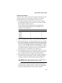
Array Migration
The Adaptec 2410SA controller supports modifying existing arrays
by expansion, migration from one array type to another, and
changing the stripe size, as described by the table below.
Current Array Type
New Array Type
RAID 0
RAID 5 or 10
RAID 1
RAID 0 or 5 or 10
RAID 5
RAID 0 or 10
RAID 10
RAID 0 or 5
To modify an array, refer to the Adaptec Storage Manager-Browser
Edition online Help.
Windows supports Online Capacity Expansion (OCE). That is, on
completion of an array expansion, the additional capacity can be
used without restarting the system. Refer to your operating system
documentation for instructions on using the additional capacity.
Drive Enclosures
The Adaptec 2410SA controller supports drive enclosures that
include either SES or SAF-TE enclosure management hardware per
the Serial ATA II, Phase 1 specification.
Hot Spares
A hot spare is a drive that is reserved to replace a failing drive in a
redundant array. In the event of drive failure, the hot spare replaces
the failed drive and the array is rebuilt.
1-6
Introduction
The Adaptec 2410SA controller supports two types of hot spares:
■
Global—Protects every array that the drive has enough
available capacity to protect.
■
Dedicated—Protects only the array that it has been assigned to
protect.
Automatic Failover
This feature allows the controller to automatically rebuild an array
when a failed drive is replaced with a new drive. This feature
applies only to redundant arrays in SES- or SAF-TE-enabled drive
enclosures. See page A-10 for details.
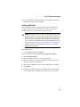
Overview of the Installation Process
The following steps provide an overview of the process of
installing, setting-up, and configuring the controller:
1 Read and understand this entire chapter.
2 Install and configure the controller and hard drives according to
the instructions in Chapter 2, Installing the Controller.
3 In Chapter 3, Installing the Driver, the procedure depends on
your system:
In a new system:
a Build the array.
b Install the controller driver at the beginning of the operating
system installation.
In an existing system:
a Install the controller driver.
b Build the array.
4 Install Adaptec Storage Manager – Browser Edition as
described in Chapter 4, Installing Adaptec Storage Manager –
Browser Edition.
5 Register online to receive important information about your
controller at register.adaptec.com.
1-7
Introduction
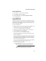
Storage Management Software Overview
The Adaptec 2410SA controller includes the following software
tools to manage your storage subsystem:
■
Adaptec Storage Manager – Browser Edition—Browser-based
storage management software that provides all of the creation,
management, and data logging needed to manage arrays.
Arrays may be set up and managed on systems using the
following operating systems:
■
Windows 2000, Windows XP, and Windows Server 2003
■
Red Hat Linux 7.3 and 8.0
■
SuSE Linux 8.0 and 8.1
For details, see Chapters 4 and 5.
■
Adaptec RAID Configuration (ARC) Utility—Part of the
controller’s built-in BIOS code. You start the ARC utility by
pressing Ctrl+A during BIOS startup. For details, see
Appendix A, Adaptec RAID Configuration Utility. The ARC
utility contains:
■
Array Configuration Utility (ACU)—Used to create,
configure, and manage arrays. Also available as a
DOS-based executable. For details, see Appendix A, Adaptec
RAID Configuration Utility.
■
SATASelect—Used to to verify the hardware configuration
of the controller and the drives.
■
Disk Utilities—Used to format and verify drives.
■
DOS Utilities—Contained on the CD.
■
Command Line Interface (CLI)—Enables you to automate
array creation or testing in a production environment using
scripts.
1-8
Introduction
Safety Information
To ensure you personal safety, as well as the safety of you equipment:
■
Keep your work area and the computer clean and clear of debris.
■
Before opening the system cabinet, unplug the power cord.
Notes and Cautions
This Installation and User’s Guide uses notes and cautions that
emphasize important information, as described below:
Note: Emphasizes important information that, if ignored,
would not result in injury, property damage, or data loss.
!
Caution: Emphasizes important information that, if ignored,
could cause equipment failure or loss of data.
Electrostatic Discharge
Electrostatic Discharge (ESD) is a natural by-product of human
activity. ESD is produced by materials that accumulate and retain
electrical charges which are transferred to people or other objects
upon contact.
!
Caution: ESD can damage electronic components when they
are improperly handled and can result in total or intermittent
failures. Always follow ESD-prevention procedures when
removing and replacing components.
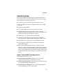
To prevent ESD damage:
■
Use an ESD wrist or ankle strap and ensure that it makes skin
contact. Connect the equipment end of the strap to an
unpainted metal surface on the chassis. If a wrist strap is not
available, ground yourself by touching the metal chassis before
handling the controller or any other part of the computer.
1-9
Introduction
■
Avoid touching the controller against your clothing. The wrist
strap protects components from ESD voltages present on the
body only. ESD voltages on clothing can still cause damage.
■
Handle your controller by its bracket or edges only. Avoid
touching the printed circuit board or the connectors.
■
When you need to put your controller down, use an antistatic
surface such as the bag supplied in your kit.
■
If you plan to return the controller to Adaptec, put it back in its
antistatic bag immediately.
1-10
2
Installing the Controller
In this Chapter...
Overview
2-1
Installing the Controller
2-2
Checking Your Controller and Devices
2-3
Determining the Boot Controller
2-3
Overview
To install the controller and drives, all you need is up to four of
each of the following:
■
Serial ATA hard disk drives
■
Serial ATA cables (supplied in this kit)
Configuration of Serial ATA devices is simple for the following
reasons:
■
There are no jumpers or switches to set on the controller or hard
drives.
■
The interface cable ends are identical, so you don’t need to
worry about which end to attach to the controller and which
end to the drive.
■
All interface connectors are keyed so that you can insert them in
only one direction.
2-1
Installing the Controller
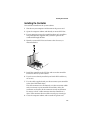
Installing the Controller
To install the controller in the system cabinet:
1 Shut down your computer and disconnect the power cord.
2 Open the computer cabinet and identify an unused PCI slot.
3 If your computer accepts low-profile brackets only, install the
low-profile bracket supplied with your kit in place of the
standard full-height bracket.
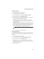
4 Identify an unused PCI slot and remove the slot cover, as
illustrated below.
5 Install the controller in the PCI slot and secure the controller
bracket to the host system cabinet.
6 If you have not already installed your Serial ATA hard drives,
do so now.
7 Use the cables supplied with your kit to connect your controller
to the Serial ATA hard drives.
The cable connectors are all identical, so it does not matter which
end you connect to your controller or hard drive. Also, the
connectors are keyed to fit the connector in only one direction.
Do not try to force a cable connector onto the controller or a
drive. If the connector does not slide on easily, try reversing it.
8 Close the computer cabinet and re-attach the power cord.
2-2
Installing the Controller
Checking Your Controller and Devices
Now that you have installed your Adaptec 2410SA controller and
connected your Serial ATA hard drives, you are ready to use the
ARC utility to check your controller and devices, as described
below:
1 Turn on your computer.
2 When prompted, enter the ARC utility by pressing Ctrl+A.
3 If your drives have already been used in another system (even if
not part of an array), select Array Configuration Utility and
initialize the drives. Otherwise, skip to the Step 4.
Note: If a drive appears to be missing, power down the
computer and check the connections.
4 Select SATASelect to verify the hardware configuration of the
controller and the drives.
Verify that all drives and controllers are shown. If anything
appears to be missing, power down the computer and check the
connections.
Determining the Boot Controller
Your Adaptec 2410SA is a bootable controller. If your computer
already contains a bootable hard drive with an installed operating
system, you can set up your computer to boot a second operating
system from the new controller.
To add a second bootable controller, you may need to enter Setup
and change the hard disk boot sequence so that the Adaptec 2410SA
controller heads the list. If Setup does not allow this change, your
system BIOS may not be configurable to allow the Adaptec 2410SA
controller to act as a second boot device.
2-3
3
Installing the Driver
In this Chapter...
Creating the Driver Disk
3-2
Windows
3-3
Linux
3-5
UnixWare and OpenUNIX
3-7
This chapter presents several scenarios for installing the controller
driver. The scenarios depend on the following terminology:
■
New system—The computer has no operating system and the
driver installation is a part of the operating system installation.
■
Existing system—The computer has an operating system and
the Adaptec 2410SA is being installed as a secondary controller.
Adaptec recommends the following driver installation workflow:
1 Create a driver disk. See Creating the Driver Disk on page 3-2 for
details.
2 Identify the appropriate operating system and installation
scenario for your computer.
3 Familiarize yourself with the supported RAID types. You will
need to select a RAID type during your driver installation. See
Appendix D for details.
4 Read and understand the entire installation procedure.
5 Proceed with the installation.
3-1
Installing the Driver
Creating the Driver Disk
Installing a driver is easier if you create a driver disk. To create the
driver disk:
1 Set your system BIOS so that your computer boots from the
CD-ROM drive.
2 Insert the Adaptec installation CD and turn on the computer.
3 Follow instructions and respond to prompts as necessary to get
to the Adaptec Start Menu.
4 Click Create Driver Disk. Then, select the appropriate
operating system.
5 Select the appropriate floppy drive letter. Then, choose the
appropriate format. (You need a full format only if the disk has
never been formatted or may have bad sectors.)
6 Insert a floppy disk and then click OK. The system creates the
driver disk.
7 Remove and label the driver disk.
Now that you have created your driver disk, identify the appropriate
driver installation scenario and proceed with the installation.
Creating the Linux Driver Disk
When creating a driver disk for Linux, use:
■
i386—For Intel 386 or 486 computers
■
i586—For Pentium I or II computers
■
i686—For Pentium III, IV, or AMD K-6 computers
■
Athlon—AMD Athlon computers
3-2
Installing the Driver
Windows
The following sections describe procedures for installing the
controller with Windows 2000, Windows XP, or Windows
Server 2003. The following installation scenarios are described:
■
Installing the Driver in a New System on page 3-3
■
Adding the Driver to an Existing System on page 3-4
Installing the Driver in a New System
In this scenario, you are installing the controller in a new Windows
system. To install the driver:
1 Install and configure the controller and hard disk drives
according to the instructions in Chapter 2.
2 Start the system and then press Ctrl-A to enter the BIOS-based
configuration utility. Use the configuration utility to create the
array and logical drive to which you will install Windows. For
details, see Checking Your Controller and Devices on page 2-3.
3 After the array is built, insert the Windows setup CD and restart
the system to begin the Windows installation.
4 When prompted to install a third-party driver, press F6.
Note: When F6 is active, a prompt appears at the bottom of
the screen for only 5 seconds. If you miss your chance to
press F6, restart the computer.
5 Insert the driver disk and wait until prompted to install a
driver. Press S to specify that the driver is on the floppy disk,
and then press Enter. The computer reads the disk.
6 When the Adaptec driver is found, press Enter. Follow the
on-screen instructions, responding as needed to complete the
installation.
3-3
Installing the Driver
Adding the Driver to an Existing System
In this scenario, you are adding the driver to an existing Windows
system. To install the driver:
1 Install and configure the controller and hard disk drives
according to the instructions in Chapter 2.
2 Start Windows. Windows launches the Found New Hardware
Wizard, which searches for the controller driver.
3 Insert the driver disk, select the floppy drive as the source and
then click Next.
4 Click Next in the succeeding two windows that appear and
follow the on-screen instructions to complete the controller
installation.
5 Remove the driver disk and restart the system.
3-4
Installing the Driver
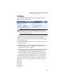
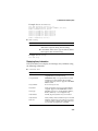
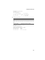
Linux
The controller supports Red Hat and SuSE Linux versions as described
in the table below.
Red Hat
SuSE
Version
Kernel Version
Version
Kernel Version
7.3
2.4.18-3
8.0
2.4.18
8.0
2.4.18-14
8.1
2.4.19
Notes
■
If you do not find your kernel version listed above, either of the
following conditions may apply:
■
Your kernel contains embedded drivers
■
Drivers are not available and you need to create a custom
driver.
■
SuSE Linux only—The controller is not supported as a bootable
controller. In other words, you can only add the driver to an
existing system.
■
For the most up-to-date information on Adaptec’s support of
Linux, visit www.adaptec.com.
Installing the Driver in a New Red Hat System
In this scenario, you are installing the controller in a new Red
Hat 7.3 or 8.0 Linux system. To install the driver:
1 Install and configure the controller and hard drives according to
the instructions in Chapter 2.
2 Turn on the computer. During startup, press Ctrl+A to start the
ARC utility. Use the ARC utility to create the array. For details,
see Checking Your Controller and Devices on page 2-3.
3 Insert the Red Hat CD Disk 1 in the CD drive.
4 Restart the computer.
5 When the Red Hat Welcome screen appears, type expert at the
boot prompt.
3-5
Installing the Driver
6 When prompted, insert the driver disk and then select OK.
7 Follow the prompts to set up your preferred environment.
8 If you intend to install other third-party devices, proceed with
the installation of those devices. Otherwise, select Done.
9 Proceed with the Linux installation according to the Red Hat
instructions.
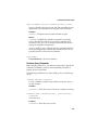
Adding the Driver to an Existing System
These driver installation instructions apply to both Red Hat and
SuSE Linux systems. To install the driver:
1 Ensure that the CD drive is mounted and then install the driver
RPM. This can be done by typing:
rpm -Uvh <mount-point>/packages/Linux/driver_package/
aacraid-*.i386.rpm
2 Run fdisk, mkfs, and create mount points for any new drives.
3-6
Installing the Driver
UnixWare and OpenUNIX
Although the driver disk you create for UnixWare 7.1.1 and
OpenUNIX 8 differ, the installation procedures for these operating
systems are the same.
Installing the Driver on a New System
In this scenario, you are installing the controller in a new
UnixWare 7.1.1 or OpenUNIX 8 system.
To install the driver:
1 Install and configure the controller and hard disk drives
according to the instructions in Chapter 2.
Early in the operating system installation, you are shown a
window labeled Choose One.
2 Insert the driver disk, select Install HBA diskette and then
press F10.
The driver loads from the driver disk. Then, the HBA screen is
displayed.
3 Select Proceed with Installation and then press F10.
4 Complete the installation as appropriate.
5 When the installation is finished, remove the driver disk and
restart the system.
Adding the Driver to an Existing System
In this scenario, you are adding the driver to an existing
UnixWare 7.1.1 or OpenUNIX 8 system.
To install the driver:
1 Shut down the computer. Install and configure the controller
and hard disk drives according to the instructions in Chapter 2.
2 Turn on the computer. Then, insert the driver disk.
3 To run the pkgadd utility, type pkgadd -d diskette1 and then
press Enter. UNIX reads the disk and package information.
4 Press Enter.
5 Restart the system. The system rebuilds the kernel automatically.
6 Add devices to the controller.
3-7
4
Installing Adaptec Storage
Manager – Browser Edition
In this Chapter...
Overview
4-1
Supported Browsers
4-2
Typical, Custom, and Compact Installations
4-2
Installing Adaptec Storage Manager on Windows
4-4
Installing Adaptec Storage Manager on Linux
4-8
Installing Adaptec Storage Manager on UNIX
4-9
Overview
This chapter discusses the installation procedure for installing
Adaptec Storage Manager – Browser Edition to enable remote and
local management of arrays. For instructions on using this
application, see Chapter 5.
4-1
Installing Adaptec Storage Manager – Browser Edition
Supported Browsers
To run Adaptec Storage Manager – Browser Edition, your
computer must have a Web browser supporting JavaScript and
cookies only. The following versions are supported:
■ On Windows
■ Internet Explorer (IE) 5.0 or later
■ Netscape 7 or later
■ On Linux
■ Adaptec-supplied and installed version of Mozilla
■ Netscape 7 or later
When using Adaptec Storage Manager, you need to log on to your
system with administrator privileges.
Typical, Custom, and Compact Installations
You can select from the following setup options:
■
Typical (default)—Supports local and remote management;
however, Adaptec SNMP is not included.
■
Custom—For expert users. Primarily used to Web Server or
when you want to make sure SNMP and Notifier are available
for a managed system. You can select from the following
components:
■
■
Managed System Components—If you select this option
only, the installation is the same as a Compact installation.
■
Adaptec Web Server—Installs components allowing
managed systems to communicate with Web browsers.
■
Adaptec Storage Manager Notifier—Installs messaging,
including email and broadcaster capabilities.
■
Adaptec SNMP—Installs components used by SNMP-based
applications. Requires Microsoft SNMP agents to be
installed to function. Not included in a Typical installation.
Compact—Installs only the components required on a managed
system. See Managed System Components (above).
Note: When you perform a Typical or Compact installation,
components needed for communication and remote management
are installed automatically.
4-2
Installing Adaptec Storage Manager – Browser Edition
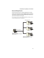
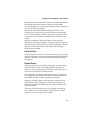
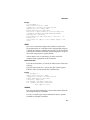
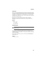
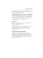
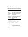
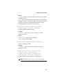
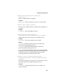
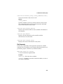
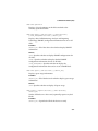
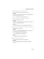
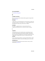
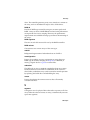
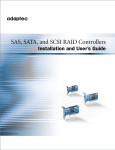
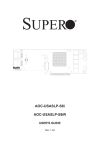
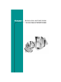
Remote and Managed Systems
The illustration below shows a typical configuration of a single
remote system connected to several managed systems. The remote
system does not necessarily contain a RAID controller; however, it
must contain, at minimum, the Adaptec Web Server and a browser
(either Internet Explorer or Netscape).
The managed systems contain RAID controllers and arrays, and at
least the Managed System Components.
Managed Systems
Remote System
Adaptec Storage Manager - Browser Edition
Minimum Requirements:
Web Browser (Internet Explorer or Netscape)
Adaptec Web Server
Adaptec Storage Manager - Browser Edition
Minimum Requirements:
Managed System Components (Compact)
4-3
Installing Adaptec Storage Manager – Browser Edition
Installing Adaptec Storage Manager on Windows
Note: When installing on a FAT 32 file system, the folder being
installed is automatically hidden.
To install Adaptec Storage Manager – Browser Edition:
1 Verify that a supported browser is installed. See Supported
Browsers on page 4-2 for details.
2 Insert the Adaptec installation CD and wait for the Autorun
executable to start the installation. If this does not occur, browse
the CD and click Autorun.
3 Click Install Adaptec Storage Manager – Browser Edition.
4 Click Next in the Install Shield window.
5 Read the license agreement. If you agree to its terms, click Yes. If
not, click No and terminate the installation.
The Select a Setup Type window appears. It provides three
types of installations: Typical, Compact, and Custom. See Typical,
Custom, and Compact Installations on page 4-2 for details.
6 Select a setup type and then click Next.
7 When you see the Destination Folder, click Next.
8 When you see the Setup Information, click Next.
The Setup Status window shows progress using a scroll bar.
Before the scroll bar shows the installation is completed,
another window pops up indicating that a security certificate
has been generated.
9 Click OK.
The Root Certificate Store window appears.
10 Click Yes.
The security certificate generated during installation is added to
the Certificate Store. If you click No now, you will need to
install the certificate the first time you run Adaptec Storage
Manager.
4-4
Installing Adaptec Storage Manager – Browser Edition
11 When prompted to restart your computer, accept the default
(Yes) and click Finish.
12 The system restarts to complete the installation.
13 Remove the Adaptec installation CD before the system restarts.
Configuring Internet Browsers on Windows
If you are managing a local storage array and your computer uses a
proxy server, you need to configure your browser to enable
Adaptec Storage Manager to bypass the proxy server. Also, if you
are managing remote systems, you need to configure Adaptec
Storage Manager to bypass the proxy server when communicating
with these systems.
The following procedures are described in this section:
■
Configuring Internet Explorer for Local Management on page 4-6
■
Configuring Internet Explorer for Remote Management on page 4-7
■
Configuring Netscape Navigator for Local Management on page 4-7
■
Configuring Netscape Navigator for Remote Management on page 4-7
4-5
Installing Adaptec Storage Manager – Browser Edition
Configuring Internet Explorer for Local Management
When using the High security setting, you must enable the
following settings manually:
■
JavaScript
■
Cookies (not stored)
You do not need to enable the following custom level security
settings for the local intranet in Internet Explorer 5 and 5.5. Select
Tools > Internet Options to access these settings:
■
Active Scripting
■
Allow per session cookies (not stored)
Note: In Internet Explorer 6.0 there is no security setting for
cookies. Cookie configuration was removed from the
Privacy tab. There is no setting for blocking Intranet cookies.
If you are using a proxy server to access the Internet, you must
bypass the proxy server to access the Adaptec Storage Manager
Web server. To verify whether you are using a proxy server:
1 From Internet Option window, click the Connections tab.
2 Click LAN Settings.
■
If the Use a proxy server box isn’t checked, exit by clicking
OK. (You aren’t using a proxy server, so ignore this setting.)
■
If the Use a proxy server box is checked, make sure the
Bypass proxy server for local addresses box is also checked.
Then, click the Advanced button. In the Exceptions window,
enter localhost as an entry.
You are now ready to proceed to Chapter 5, Using Adaptec Storage
Manager – Browser Edition.
4-6
Installing Adaptec Storage Manager – Browser Edition
Configuring Internet Explorer for Remote Management
If you know the IP address of the managed system you want to
manage remotely:
1 Select Tools > Internet Options > Connections > LAN Settings.
2 Select Use a proxy server for your LAN > Advanced.
3 In the Exceptions section, type the managed system’s IP
address.
Configuring Netscape Navigator for Local Management
Note: These instructions apply specifically to Version 7 and may
differ in later versions.
To configure Netscape Navigator:
1 Log into your computer with administrator access.
2 Select Edit > Preferences.
3 In the Preferences window, click the right arrow on the Privacy
and Security line. Ensure that one of the Enable cookies
selections is selected.
4 Select the Advanced line. Ensure that Enable Javascript for
Navigator is checked.
5 Exit Navigator, then restart it. This enables any settings you
have modified.
6 You are now ready to proceed to Chapter 5, Using Adaptec
Storage Manager – Browser Edition.
Configuring Netscape Navigator for Remote Management
If you know the IP address of the managed system you want to
manage remotely:
1 Select Edit > Preferences > Advanced > Proxies > Manual
proxy configuration > No Proxy For
2 Type the managed system’s IP address.
4-7
Installing Adaptec Storage Manager – Browser Edition
Installing Adaptec Storage Manager on Linux
Note: When performing this installation, keep in mind that Linux
is case sensitive.
To install Adaptec Storage Manager on a Linux computer and
configure the desired Internet browser:
1 Insert the Adaptec installation CD.
2 Install the software by typing:
sh <mount-point>/install.sh.
The <mount-point> differs among computers, but
/mnt/cdrom, /media/cdrom, or cdrom usually works.
A Welcome window appears.
3 Click Next.
The License Agreement window appears.
4 Read the license agreement. If you agree to its terms, click
Accept. If not, click Cancel and terminate the installation.
The Select a Setup Type window appears. It provides three
types of installations: Typical, Compact, and Custom. See Typical,
Custom, and Compact Installations on page 4-2 for details.
5 Select a setup type and click Next.
The Start Copying window appears.
6 Click Next.
The Running Non-Interactive Setup window displays the files
being loaded onto the system.
7 Click Next when prompted.
A Setup Complete window appears.
8 Click Complete.
A message window appears reminding you that any proxy
servers must be bypassed for the RAID management
application to work.
4-8
Installing Adaptec Storage Manager – Browser Edition
9 Click OK.
The Shell window you used to launch the installation indicates
that some daemons are being started.
The installation creates a shortcut to Adaptec Storage Manager
in the System tab. This shortcut launches Adaptec Storage
Manager using Netscape.
Unless the controller driver was installed as part of this
installation, you do not need to restart your computer.
10 Remove the Adaptec installation CD.
Your computer must have a Web browser supporting JavaScript
and cookies. To use Adaptec Storage Manager, you need to log on
to your computer with root privileges.
Installing Adaptec Storage Manager on UNIX
Your UNIX system may only be used as a managed system.
Therefore, you can use only the following installation options:
■
Compact—Installs the managed system components.
■
Advanced—You select the managed system components. If using
third-party applications requiring remote communications, you
can add the SNMP agent.
To install Adaptec Storage Manager, type:
sh <mount-point>/install.sh
where <mount-point> is usually /mnt/cdrom or cdrom.
(Remember that Unix is case sensitive.) The install script automatically
determines the components needed for your computer and performs
the installation.
4-9
5
Using Adaptec Storage Manager –
Browser Edition
In this Chapter...
Overview
5-2
Architecture Overview
5-3
Logging In
5-4
Installing a Security Certificate
5-6
Registering Your Software
5-6
The Basics
5-7
5-1
Using Adaptec Storage Manager – Browser Edition
Overview
This chapter describes how to use Adaptec Storage Manager –
Browser Edition to manage arrays. Once you are logged in, you
will find convenient online help to guide you through the details of
creating, configuring, and managing arrays.
Note: Your controller may not support all of the features
described. In most cases if a feature is not supported by your
controller the feature does not appear in the interface.
With Adaptec Storage Manager, you can:
■
Locally manage a system containing a supported Adaptec
RAID controller that has Windows or Linux and a supported
browser.
■
Remotely manage any system containing a supported Adaptec
RAID controller that has Managed System Components. (See
Typical, Custom, and Compact Installations on page 4-2.). You can
manage a system remotely from a system that does not contain
a RAID controller.
UNIX Systems Only: The remote system (the system doing
the managing) must have the ARCPD agent installed.
These same Windows and Linux systems can also be managed
remotely by either of the following methods:
■
Installing Adaptec Storage Manager on the remote system.
■
Directing the browser on the remote system to the system you
want to manage.
Note: To manage an array remotely from a Linux system,
install Adaptec Storage Manager on the system and use
the Adaptec-supplied version of Mozilla as the browser.
5-2
Using Adaptec Storage Manager – Browser Edition
Architecture Overview
A locally managed system requires all of the following
components:
■
A supported Web browser, which should already be installed
on the system.
■
The Adaptec Web service which supplies content displayed on
the Web browser.
■
An Adaptec-supplied storage agent.
A remotely managed system requires all of the following
components:
■
The remote system must contain a browser.
■
The managed system must contain an Adaptec storage agent.
■
Remote and managed systems must have a TCP/IP connection.
The Web service can be installed on the same remote system as the
browser, the system with the RAID controller installed, or a third
system.
Communication security is ensured because Secure-HTTP (S-HTTP)
or SSL protocols are used to encrypt all transmitted data. Connection
over an Ethernet network, a corporate WAN, or VPN are supported.
5-3
Using Adaptec Storage Manager – Browser Edition
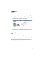
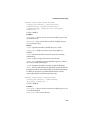
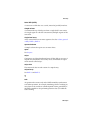
Logging In
To login:
1 Start Adaptec Storage Manager – Browser Edition.
■
In Windows, click Start > Programs > Adaptec Storage
Manager > Adaptec Storage Manager – Browser Edition.
■
In Linux, click Start > System > Adaptec Storage Manager.
The Login screen, shown below, is presented.
2 Enter the host name or IP address of the system you want to
manage and the username and password you would use to log
into that system.
3 Click Login.
Notes
When running Adaptec Storage Manager for the first time:
■
You need to install a security certificate if you chose not to
during the installation process. For instructions, see Installing a
Security Certificate on page 5-6.
■
You are asked to register your software. For instructions, see
Registering Your Software on page 5-6.
5-4
Using Adaptec Storage Manager – Browser Edition
To log in from any system with a Web browser:
1 Start the Web browser application and type the IP address for
the system you want to access in the address bar and then press
Enter. For example, https://10.6.3.14:3513/adaptec.
When connection to the remote system is established, the
System Login screen appears.
Note: If you are using a proxy server to access the Internet,
you must bypass the proxy server to access the Adaptec
Storage Manager Web server. See Configuring Internet
Browsers on Windows on page 4-5 for details.
2 Enter the host name or IP address of the system you want to
manage and the administrative username and password that
you would normally use to log into that system.
3 Click Login.
5-5
Using Adaptec Storage Manager – Browser Edition
Installing a Security Certificate
If you chose not to install a security certificate when you installed
Adaptec Storage Manager – Browser Edition, you must install the
certificate when you run the application for the first time.
To create the certificate:
1 When the Security Alert window appears, click View Certificate.
2 When the Certificate window appears, click Install Certificate.
3 When the Certificate Import wizard, appears, click Next.
The Certificate Import wizard window’s contents change.
4 Accept the default, Automatically select the certificate store,
and click Next.
5 On the root Certificate Store window, click Yes.
Another small Certificate Import wizard appears.
6 Click OK.
The Certificate window mentioned in Step 2 reappears.
7 Click OK.
You are returned to the Security Alert window from Step 1.
8 Click Yes to finish the creation and storage of the certificate.
Registering Your Software
After installing and creating a security certificate, you are asked to
register the product. To use Register Now, your computer must
have an Internet connection. If you need to delay registration, click
Register Later. If you choose Register Later, you will be prompted
to register the application the next time you run it.
5-6
Using Adaptec Storage Manager – Browser Edition
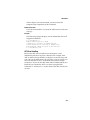
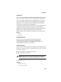
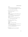
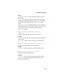
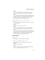
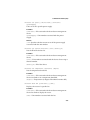
The Basics
An example of a typical Adaptec Storage Manager – Browser
Edition screen is shown below.
Note: Depending on your operating system, browser, and
color scheme you may notice some differences between this
illustration and your screen.
The header frame, at the top of the screen, contains the name of the
system that you are currently connected to and a number of
buttons that perform various actions or open additional windows.
The action buttons are:
■
Logout—Selecting Logout ends your session and returns you to
the Login screen.
■
Rescan—Used to rescan the configuration of the system.
Typically, when a rescan is required, it occurs automatically, for
example, after an array is created.
However, the system configuration can change without Adaptec
Storage Manager being notified. For example, drives that are
inserted or removed from a nonintelligent enclosure or an
enclosure powered on after you logged into Adaptec Storage
Manager would not be displayed unless you manually rescan.
The remaining buttons open additional windows that provide
more detailed information and allow you to perform actions or
change settings on a specific aspect of your storage subsystem.
These are:
■ Events
■ Options
■ Help
■ Properties
■ Tasks
5-7
Using Adaptec Storage Manager – Browser Edition
Immediately following the header frame is a controller information
line including the model number of the first Adaptec RAID
controller found in the system and the amount of cache memory (if
any) installed on that controller.
Beneath the controller information are Physical Devices and
Logical Devices views that show connected devices and existing
arrays on this controller. Controller information and device views
are repeated for each additional Adaptec RAID controller in the
system.
Select the controller by clicking anywhere on the controller
information. When the controller is selected, the Events, Properties
and Tasks buttons change from blue to amber. Clicking any of them
displays an additional window with information and options
specific to this controller.
Pop-Up Tool Tips
If you position the cursor over a device or button a pop-up tool tip
appears. For buttons, the tips contain helpful information about the
function of the button, while for devices they display additional
information.
Physical Devices
The Physical Devices view displays information about the drives
and enclosures attached to the Adaptec RAID controller. The
devices are shown organized by the channel or port that they are
connected to and shown in numerical order.
The display for each channel includes information on maximum
speed capability, the number of the channel on the controller, and
the number of devices found (excluding the controller).
Selecting a channel or device turns the Events, Properties, and
Tasks buttons amber. Clicking any of these buttons displays an
additional window with information and options specific to that
device or channel.
At the top of the Physical Devices view, grouped to the right of
View, are three view selection buttons. These buttons select the
physical devices connected to this controller.
5-8
Using Adaptec Storage Manager – Browser Edition
Changing How Drives are Displayed
By default, the Physical Devices displays a condensed view of the
controller configuration that hides detailed information about the
drives. More information is available by either positioning the
mouse pointer over the device or clicking on the arrowhead to the
left of a row of devices.
The selected display mode button will appear in a lighter shade of
blue than the other two buttons. The default display is the Text
Description View, but in the condensed view used when Adaptec
Storage Manager is loaded, the display is the same in all three
modes.
If you change the display mode by selecting one of the other view
buttons, a yellow arrow flashes to the left of any devices where the
condensed display omits information.
An icon is always the first entry on each device line. The
icon is
used to represent a hard disk drive. If a + symbol appears with the
hard disk drive icon
, the drive is a hot spare. Different icons are
used to represent other devices.
View
is the default display mode and when expanded, will show the
following information about each device:
■
Capacity of the drive
■
Drive manufacturer and model number
■
Drive ID, or Serial ATA port number
When expanded, the Full Size Capacity View button
and the
Relative Size Capacity View button
represent each drive as a
bar. A drive that is not used as part of any array is shaded blue
surrounded by a dotted line.
displays a full-length bar for each drive, regardless of capacity.
displays a bar for each drive, with the largest capacity drive
full-length and the other drives proportional to the drive capacity,
relative to the largest drive.
5-9
Using Adaptec Storage Manager – Browser Edition
Any part of a drive used in an array is shown as a gray segment
within the bar. Selecting any gray segment will highlight it in
amber and, in the Logical Devices view, highlight the array of
which this segment is a member.
In either the Full Size Capacity View or the Relative Size Capacity
View, a small portion at each end of the drive may be shown in
dark gray.
The segment at the end of the drive may vary in size from drive to
drive because, in addition to the RAID signature, the controller
may also limit the usable capacity of each drive.
This is done because hard disk drives of apparently the same
capacity from different manufacturers, or even different models
from the same manufacturer, actually vary slightly in the true
capacity available. Although, in normal operation this is not an
issue, it can be when assigning hot spares or replacing a failed drive.
If the controller used the maximum capacity of each drive and a
hot spare or replacement drive was just a few megabytes smaller, it
would not be able to replace the failed drive. By rounding drive
capacities downward, this possibility is effectively eliminated.
Logical Devices
As described earlier, when Adaptec Storage Manager loads, the
Logical Devices view is expanded and you can see the arrays
present on the controller.
At the top of this view are the following buttons: Create, Modify,
and Delete. Each button opens a wizard for the corresponding
function.
Modify allows you to:
■
Change an array from one RAID level to another
■
Expand an array
■
Change the stripe size for a RAID 0
For detailed instructions on these buttons, refer to the online Help.
5-10
Using Adaptec Storage Manager – Browser Edition
The main area of the Logical Devices view is used to display the
arrays on this controller. It defaults to a condensed view of toplevel arrays.
Note: The Options button allows you to display second-level
arrays if your controller supports them.
In this condensed view, the RAID level of each device as well as
whether it is protected by a hot spare, is visible.
If a global hot spare exists, all arrays that the hot spare is large
enough to protect will show as protected.
In the expanded view, the icons for the arrays are arranged
vertically and alongside them are the capacity, name, and type of
array.
Selecting an array by clicking on it will highlight the following in
amber:
■
All the drives or segments that form the array in the Physical
Devices view.
■
Any second-level arrays that form a top-level array in the
Logical Devices view.
■
The Events, Properties, and Tasks buttons in the header frame.
Selecting any of these three buttons displays a new window
with additional information and options specific to that array.
5-11
A
Adaptec RAID
Configuration Utility
In this Appendix...
Using the Array Configuration Utility
A-2
Using SATASelect
A-9
Using the Disk Utilities
A-11
Viewing the Event Log
A-12
The Adaptec RAID Configuration (ARC) utility is an embedded
BIOS utility that includes:
■
Array Configuration Utility (ACU)—Used to create, configure,
and manage arrays. Also used to initialize and rescan drives.
(Also available as a stand-alone DOS utility as described in Using
the Array Configuration Utility (ACU) on page B-11.)
■
SATASelect—Used to change device and controller settings,
■
Disk Utilities—Used to format or verify media.
To run the ARC utility, press Ctrl+A when prompted by the
following message during system startup:
Press <Ctrl><A> for Adaptec RAID Configuration Utility
A-1
Adaptec RAID Configuration Utility
The Adaptec RAID Controller menu appears, presenting the
following options:
■
Array Configuration Utility
■
SATASelect Utility
■
Disk Utilities
To select an option from this menu, or from any of the menus within
ARC, browse with the arrow keys and then press Enter. In some
cases, selecting an option displays another menu. To return to the
previous menu at any time, press Esc.
The following sections discuss each of these menu options.
Using the Array Configuration Utility
The Array Configuration Utility (ACU) enables you to manage,
create, and delete arrays from the controller’s BIOS. You can also
initialize and rescan drives.
You can use the ACU to create a bootable array for the system. We
recommend that you configure the system to boot from an array
instead of a single disk to take advantage of the redundancy and
performance features of arrays. For details, see Making an Array
Bootable on page A-3.
Managing Arrays
Use the Manage Arrays option to view array properties and
members, make an array the boot array, manage failover
assignments, and delete arrays. The following sections describe
these operations in greater detail.
A-2
Adaptec RAID Configuration Utility
Viewing Array Properties
To view the properties of an existing array:
1 At the BIOS prompt, press Ctrl+A.
2 From the ARC menu, select Array Configuration Utility.
3 From the ACU menu, select Manage Arrays.
4 From the List of Arrays dialog box, select the array you want to
view information on and then press Enter.
Single Level Arrays Only—For RAID levels 0, 1, and 5, the
Array Properties dialog box shows detailed information on the
array physical disks.
Dual-Level Arrays—For RAID 10s, to view detailed information
on the array physical disks, highlight the displayed member and
then press Enter to display the second level. Press Enter again to
display the physical disks associated with the array.
Note: A failed drive is displayed in a different text color.
5 Press Esc to return to the previous menu.
Making an Array Bootable
You can make an array bootable so that the system boots from the
array instead of from a stand-alone (single) disk. To make an array
bootable:
1 At the BIOS prompt, press Ctrl+A.
2 From the ARC menu, select Array Configuration Utility.
3 From the ACU menu, select Manage Arrays.
4 Select the array you want to make bootable and then press
Ctrl+B. This changes the selected array’s number to 00, making
it the controller’s boot array.
5 Restart the system.
A-3
Adaptec RAID Configuration Utility
Notes
■
If the controller is not a boot device, you can disable its runtime
BIOS, see page A-10. When the BIOS is disabled, it does not
occupy any of the expansion ROM region of the system’s
memory map. In a system with several expansion ROMs,
disabling the BIOS may be helpful.
■
You cannot make a non-00 array bootable while the array is in a
build/verify or reconfiguration process.
■
The controller always uses the lowest numbered array as its
bootable array. If you delete Array 00 for any reason, the next
lowest numbered array becomes the bootable array. Use the
Ctrl+B option to mark the correct array as the bootable array
(by making it Array 00).
■
If you want to boot from a stand-alone (single) disk drive, first
create a volume on that disk.
■
The system BIOS provides additional tools to modify the boot
order. For more information, refer to your system documentation.
Deleting Arrays
!
Caution: Back up the data on an array before you delete it.
When you delete the array, you loose all your data on the
array. You cannot restore deleted arrays.
To delete an existing array:
1 At the BIOS prompt, press Ctrl+A.
2 From the ARC menu, select Array Configuration Utility.
3 From the ACU menu, select Manage Arrays.
4 Select the array you wish to delete and then press Delete.
5 In the Array Properties dialog box, press Delete again and then
press Enter. the following message is displayed:
Warning!! Deleting will erase all data from the array.
Do you still want to continue? (Yes/No):
A-4
Adaptec RAID Configuration Utility
6 Select Yes to delete the array or No to return to the previous
menu. At the Array Properties dialog box, select Delete again
and then press Enter.
7 Press Esc to return to the previous menu.
Managing Failover Drive Assignments
To assign a hot spare drive to an array:
1 Select Manage Arrays from the Main menu.
2 From the List of Arrays dialog box, select the array to which
you want to assign a hot spare, and then press Ctrl+S. The
Hotspare Management for Array dialog box is displayed, which
shows the drives that can be assigned as hot spare drives.
3 Select a drive and then press Insert to assign the drive as a hot
spare. The specified drive is displayed in the Assigned
Hotspares drives list.
4 Press Enter to save the hot spare drive assignment. the
following message is displayed:
Have you finished managing Hotspare drives?
5 Press Y (for yes) to return to the Main menu.
To remove an assigned hot spare drive from an array:
1 Select Manage Arrays from the Main menu.
2 From the List of Arrays dialog box, select the array from which
you want to remove the assigned hot spare drive and press
Ctrl+S. The Hotspare Management for Array dialog box is
displayed, which shows a list of drives that can be assigned as
hot spare drives and a list of drives that are assigned as hot
spare drives.
3 From the Assigned Hotspares drives list, select the drive to be
removed and then press Delete. The specified drive is
displayed in the Select Hotspares drives list.
4 Press Enter to save the removed hot spare drive assignment. the
following message is displayed:
Have you finished managing Hotspare drives?
5 Press Y (for yes) to return to the Main menu.
A-5
Adaptec RAID Configuration Utility
Creating Arrays
Before creating arrays, make sure the disks for the array are
connected and installed in your system (or enclosure). Note that
any disks with MS-DOS partitions, disks with no usable space, or
disks that are uninitialized appear dimmed and cannot be used for
creating a new array. For information on how to initialize a disk
drive, see page A-8.
To create an array:
1 Shut down and restart the system.
2 At the BIOS prompt, press Ctrl+A.
3 From the ARC menu, select Array Configuration Utility.
4 From the ACU menu, select Create Array.
5 Browse with the arrow keys to select a channel.
6 Select the disks for the new array and then press Insert. ACU
displays the largest usable space available for each disk. You
can use available space from multiple disks for the new array.
To deselect any disk, highlight the disk and then press Delete.
Note: The ACU cannot reliably find disks or enclosures that
were powered up after system power-up. Therefore,
power up enclosures prior to powering up the host.
7 Press Enter when all disks for the new array are selected. The
Array Properties menu is displayed.
After you install a controller in a system and start it for the first
time, the BIOS announces the configuration it has detected. This
configuration may not match your system’s configuration.
!
Caution: If you do not take any action within 30 seconds, the
system automatically accepts the configuration. If the
configuration does not match your system, reject it or enter the
ARC utility. Otherwise, the array configuration may be erased.
If necessary, enter the ARC utility. Upon entering ARC, accept the
configuration that ARC reports, and then modify the configuration
to suit your needs.
A-6
Adaptec RAID Configuration Utility
Assigning Array Properties
The ACU can be used to assign array properties only prior to array
creation. (After the array is created, you need to use Adaptec
Storage Manager.) To assign properties to the new array:
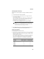
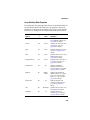
1 In the Array Properties menu, select an array type and then
press Enter. The display shows only the array types available
for the number of drives selected.
The maximum number of drives allowed and minimum
number of drives required depends on the RAID level, as
described in the table below.
RAID Level
Simple volume
Maximum Drives Allowed
4
Minimum Drives Required
1
RAID 0
RAID 1
4
2
2
2
RAID 5
RAID 10
4
4
3
4
2 Type in an optional label for the array and then press Enter.
3 Enter the desired array size. The maximum array size available
based on the segments you selected is displayed automatically.
If you want to designate a different array size, type the desired
array size and select MB (megabytes), GB (gigabytes), or TB
(terabytes) from the drop-down list. If the available space from
the selected segments is greater than the size you specify, the
remaining space is available for use in other arrays.
4 Select the desired stripe size. The allowable stripe sizes are 16,
32, and 64 KB (the default). The default stripe size provides the
best overall performance in most network environments.
5 Specify whether you want to enable read and write caching for the
array.When Enabled (the default), caching is enabled, providing
maximum performance. When Disabled, caching is disabled.
!
Caution: When caching is Enabled, there is a potential for
data loss or corruption during a power failure.
Caching should usually be enabled to optimize performance,
unless your data is highly sensitive, or unless your application
performs completely random reads, which is unlikely.
A-7
Adaptec RAID Configuration Utility
6 Specify whether you want to enable write caching for the array.
When you are finished, select Done.
Initializing Disk Drives
If an installed disk does not appear in the disk selection list for
creating a new array or if it appears grayed out, you need to
initialize it before you can use it as part of an array.
!
Caution: Initializing a disk overwrites the partition table on the
disk and makes any data on the disk inaccessible. If the drive
is used in an array, you may not be able to use the array again.
Do not initialize a disk that is part of a boot array. The boot
array is the lowest numbered array (normally 00) in the List of
Arrays dialog box. (See Viewing Array Properties on page A-3
for information on determining which disks are associated
with a particular array.)
To initialize drives:
1 At the BIOS prompt, press Ctrl+A.
2 From the ARC menu, select Array Configuration Utility.
3 Select Initialize Drives.
4 Browse with the arrow keys to select a channel.
5 Browse with the arrow keys to highlight the disk you wish to
initialize and then press Insert.
6 Repeat step 5 until all the drives to be initialized are selected.
7 Press Enter.
8 Read the warning message, ensure that you have selected the
correct disk drives to initialize, and then press Y to continue.
A-8
Adaptec RAID Configuration Utility
Rescanning Disk Drives
To rescan the drives connected to the controller:
1 At the BIOS prompt, press Ctrl+A.
2 From the ARC menu, select Array Configuration Utility.
3 Select Rescan Drives.
Using SATASelect
SATASelect enables you to change device and controller settings
without opening the computer cabinet or handling the card. With
this utility, you can modify the Channel Interface Definitions and
Device Configuration Options.
To access the SATASelect:
1 When you turn on or restart your system, press Ctrl+A to access
the ARC utility when you see the following message:
Press <Ctrl><A> for Adaptec RAID Configuration Utility
2 If multiple controllers are installed, select the controller you
want to configure and then press Enter.
3 From the ARC menu, select SATASelect Utility.
The SATA Configuration and Controller Configuration menu
options are displayed.
To select a SATASelect menu option, browse with the arrow keys
to the option and then press Enter. In some cases, selecting an
option displays another menu. You can return to the previous
menu at any time by pressing Esc.
To restore the original SATASelect default values, press F6 from
the Configure/View Host Adapter Settings screen.
■
SATA Configuration Options:
■
Write Cache (Default: Enabled)—When Enabled, write
cache is enabled, providing maximum performance.
!
Caution: When Enabled, there is a potential for data
loss or corruption during a power failure.
A-9
Adaptec RAID Configuration Utility
■
■
DMA (Default: Enabled)—When Enabled, Direct Memory
Access (DMA) mode is used for the drive, providing
maximum performance.
■
SMART (Default: Disabled)—Controls the predictive
failure feature of the disk drive. When Enabled and the
drive supports Self-Monitoring, Analysis and Reporting
Technology (SMART) configuration, the SMART status of
the drive (Healthy or Failed) is displayed along with the
physical drive display during POST. Messages are logged
to the Storage Manager log file when they occur. When
Event Broadcasting is enabled for your operating system,
SMART events are also sent to destinations according to
your system’s particular configuration (for example,
system log file, Event Viewer, pop ups, email, etc.) When
Disabled, or when the drive does not support SMART, the
SMART status is not displayed.
■
Allow Read Ahead (Default: Enabled)—When Enabled,
the drive’s read ahead cache algorithm is use, providing
maximum performance under most circumstances.
Controller Configuration Options:
■
Drives Write Cache (Default: Drive's Default)—When
Enabled, write cache is enabled, providing maximum
drive performance. When Disabled, no write cache is used
on the drive. By default, the drive’s setting is used.
!
Caution: When Enabled, there is a slight possibility
(less than with controller cache) of data loss or
corruption during a power failure.
■
Runtime BIOS (Default: Enabled)—When Enabled, the
Adaptec 2410SA controller BIOS allows the controller to
act as a bootable device. Disabling the BIOS allows
another suitable controller to act as the boot device.
■
Automatic Failover (Default: Enabled)—When Enabled,
the controller automatically rebuilds an array when the
failed drive is replaced. When disabled, the array must be
rebuilt manually.
A-10
Adaptec RAID Configuration Utility
■
Array Background Consistency Check (Default:
Disabled)—When Enabled, the controller continuously
performs a verification on a redundant array to data
integrity. In the case of RAID 1 or 10, consistency checks
assure that the data between like blocks match. In the
case of a RAID 5, consistency checks assure that data in
the stripe and the calculated parity for the stripe match.
Consistency checking processes reduce performance. For
a RAID 5, the performance reduction is significant.
■
BBS Support (Default: Enabled)—When Enabled in systems
that support BBS, controller is presented as a bootable
device in the host system's BIOS for boot device selection.
■
Array-based BBS Support (Default: Disabled)—When
Enabled in systems that support BBS, the controller
presents attached bootable devices up to the host
system's BIOS for boot device selection. This is relevant
for logical arrays.
■
Physical Drives Display during POST (Default:
Disabled)—When Enabled, attached physical devices are
displayed during system POST. Displaying the devices
adds a few seconds to the overall POST time.
4 To exit SATASelect, press Esc until a message prompts you to exit.
(If you changed any host adapter settings, you are prompted to
save the changes before you exit.) Select Yes to exit and restart the
system. Any changes you made take effect after the system boots.
Using the Disk Utilities
The disk utilities enable you to low-level format or verify the
media of your Serial ATA hard disks. To access the disk utilities:
1 Turn on your computer and then press Ctrl+A when prompted
to access the ARC utility.
2 If multiple controllers are installed, select the controller you
want to configure and then press Enter.
3 From the ARC menu, select Disk Utilities.
4 Select the desired disk and then press Enter.
You are offered the following options:
A-11
Adaptec RAID Configuration Utility
■
Format Disk—Simulates a format of the hard drive by
removing the file system and writing zeros to the entire disk.
Serial ATA drives are formatted at the factory and do not
need to be formatted again.
!
■
Caution: Formatting destroys all data on the drive. Be
sure to back up your data before performing this
operation.
Verify Disk Media—Scans the media of a disk drive for
defects. Any errors found are corrected.
Viewing the Event Log
The BIOS-based event log stores all firmware events (configuration
changes, array creation, boot activity, and so on).
The event log has a fixed size. Once full, old events are flushed as
new events are stored. Also, the log is volatile; therefore, it is
cleared after each system restart.
To access the event log:
1 When you turn on or restart your system, press Ctrl+A to access
the ARC when prompted by the following message:
Press <Ctrl><A> for Adaptec RAID Configuration Utility
2 If multiple controllers are installed, select the controller you
want to configure and then press Enter.
3 From the ARC menu, press Ctrl+P.
The Controller Service Menu appears.
4 Select Controller Log Information and then press Enter. The
current log is displayed.
A-12
B
DOS Utilities
In this Appendix...
Using the Adaptec Flash Utility (AFU)
Using the Array Configuration Utility (ACU)
B-1
B-11
Using the Adaptec Flash Utility (AFU)
The Adaptec® Flash Utility (AFU) is a DOS application used to
update the flash EEPROM components on one or more Adaptec
SCSI RAID controllers. The utility can also be used to verify a
controller’s current flash contents against the flash images in a
specified file or to save a controller’s current flash contents to a file.
Your Adaptec RAID controller uses nonvolatile flash to store onboard software, such as BIOS, microprocessor kernel, and monitor.
Whenever it becomes necessary to update any of those components
you can update your controller’s flash components using the AFU.
AFU updates the controller’s flash by reading flash image data
from a supplied User Flash Image (UFI) file and writing it to the
controller’s flash components. A UFI file contains all of a
controller’s flash images, as well as information about each image.
It also includes general controller information, such as controller
type, to ensure that AFU uses the correct UFI file when updating
the controller’s flash.
B-1
DOS Utilities
The process of updating a controller’s flash must be done carefully
to avoid rendering the controller inoperable. AFU is designed to be
easy to use with all the necessary safeguards to prevent a user from
accidentally damaging the controller’s flash contents.
Overview of the AFU
The AFU performs the following primary functions:
■
Update—Updates all the flash components on a controller with
the flash image data from a UFI file.
■
Save—Reads the contents of a controller’s flash components
and saves the data to a UFI file. This enables you to later restore
a controller’s flash to its previous contents should the need
arise.
■
Verify—Reads the contents of a controller’s flash components
and compares it to the contents of the specified flash image file.
■
Version—Displays version information about a controller’s
flash components.
■
List—Lists all the supported controllers detected in your
system.
See Running the AFU on page B-4 for command details.
System Requirements
The requirements for AFU are as follows:
■
AFU runs under MS–DOS version 5.0 or later. It cannot run
from a DOS command prompt window under any version of
Windows.
You must shut down your operating system and reboot to DOS
to use the AFU. To start MS–DOS, boot from a bootable MS-DOS
floppy disk or from a DOS partition on a bootable drive.
■
AFU requires at least 8 MB of extended memory.
■
AFU does not run with any DOS extenders installed in memory,
such as EMM386.SYS and DOS4GW.
AFU does support HIMEM.SYS and is compatible with other
DOS drivers running under HIMEM.SYS (for example,
SMARTDRV.SYS and SETVER.SYS).
B-2
DOS Utilities
■
The AFU can run from a partition on a drive or array attached
to the controller you are updating. Once the flash update
begins, no I/O is possible to any array attached to that
controller until the flash operation is completed and the system
is restarted.
■
If you want to update multiple controllers in the same system,
you should first update the boot controller’s flash, restart the
system, and then update the flash for any remaining controllers.
Firmware Floppy Disk Kit
Controller firmware is available on Adaptec installation CD, or from
www.adaptec.com.
The CD includes the AFU executable AFU.exe, the corresponding
documentation, and a separate flash image. The flash image may
be comprised of multiple UFI files.
To create a controller firmware kit on floppy disks:
1 Locate the necessary files on the Adaptec installation CD at:
packages/firmware/adpxxx
where xxx is the model number of your controller.
2 Create a bootable MS–DOS floppy disk and copy the following
files to this disk:
■
AFU.exe
■
AAxxx01.ufi
where xxx is the model number of your controller.
3 Copy the remaining UFI files to additional disks.
B-3
DOS Utilities
Running the AFU
You can run the AFU from its graphical user interface (GUI) or
from the command line.
Accessing the AFU from the GUI
To access the AFU:
1 At the DOS command prompt (typically A:\>), type AFU with no
arguments.
The main menu to the AFU is displayed.
2 Select Select Controllers and select the controllers to be flashed.
3 Select Select an Operation.
4 Select any available AFU function and follow the on-screen
instructions.
Accessing the AFU from the Command Line
At the DOS command prompt (typically A:\>), type AFU followed
by a command and any optional switches. The AFU processes the
command, prompts you to insert additional floppy disks as
needed, exits, and reports success or an error message code.
The syntax of the AFU command line is as follows:
AFU <Command> [/C<Controller ID>] [/D <UFI File Path>] [/?]
where <Command> is one of the following AFU commands:
■
HELP—Displays AFU help text.
■
LIST—Lists the AFU-supported controllers installed on this
system.
■
SAVE—Saves the contents of a controller’s flash to the specified
UFI file.
■
UPDATE—Updates a controller’s flash from the data in the
specified UFI file.
■
VERIFY—Compare the controller’s current flash to the
specified UFI file.
■
VERSION—Displays the controller’s current flash version
information.
B-4
DOS Utilities
The AFU switches are as follows
■
/C <Controller ID> is one or more controller IDs representing
the set of controllers on which to perform the specified
command. You can specify a single controller ID, for example:
/C 0
multiple IDs separated by commas, for example:
/C 0,2
or ALL to indicate all controllers.
This switch is required. If no /C switch is specified, the system
returns a fatal error message. See each individual command for
the default switch values.
■
/D <UFI File Path> specifies the path (drive and directory)
where the UFI files are located. If you do not specify the /D
switch, the AFU looks for, or creates, its UFI files in the default
location.
Note: You cannot specify the name of a UFI file, only its path.
UFI filenames are predefined, based on the controller type.
Flashing the Firmware Using AFU
The simplest way to flash the controller is to use the AFU GUI.
Follow the instructions in Accessing the AFU from the GUI on
page B-4 to start AFU with the GUI.
To flash the firmware using the AFU utility from the command
line:
1 Shut down your computer.
2 Insert the bootable disk that contains the AFU utility.
3 Turn on the computer.
4 Enter the system setup utility and verify that your computer is
set up to boot from the bootable disk.
B-5
DOS Utilities
5 At the DOS prompt, type afu list and press Enter.
This command displays a list of the controllers in your system.
Take note of the controllers you would like to update and its
number (or numbers if there are more than one). Verify that the
controller you wish to update is identified.
6 You can perform this step using any of the following
alternatives:
a Flashing the Firmware on a Single Controller—To flash the
firmware on a single controller, type:
afu update /C <controller_number>
Where <controller_number> is the number of the controller
whose firmware you are updating.
For example, to upgrade Controller 0, you would type:
afu update /C 0
b Flashing the Firmware on Multiple Controllers—To flash
the firmware on multiple controllers, type:
afu update /C <controller_number_a>,<controller_number_b>
Where <controller_number_a> and <controller_number_b>
is the number of one of the controllers whose firmware you
are updating.
To upgrade controllers 0, 2, and 3 for example, you would
type:
afu update /C 0, 2, 3
c Flashing the Firmware on All Controllers—To flash the
firmware on all controllers, type:
afu update /C all
7 The firmware image may be contained on multiple disks.
The AFU prompts you to put in the first firmware disk. When it
detects that the disk is in the drive, the AFU reads the part of
the firmware image contained on the first disk.
8 The AFU then tells you to remove the first firmware disk and
insert the second firmware disk.
B-6
DOS Utilities
9 If there are additional UFI files this process is repeated until the
complete image has been read, the controller flash is updated
with the new image.
AFU Commands
The following pages describe each of the AFU commands in detail.
For ease of use, the commands are presented in alphabetical order.
HELP
The HELP command displays a summary of AFU functions and
command switches.
To display the help text for the AFU, you can also type AFU /?
Options
None
Default Switch Values
None
Examples
A:\> AFU HELP
A:\> AFU /?
LIST
The LIST command displays the AFU-supported controllers
installed on your system. Use this command to see which
controllers are installed on this system, or to identify the ID
numbers assigned to each physical controller.
You do not have to restart the computer upon completion of this
command.
Options
None
Default Switch Values
None
Example
A:\> AFU LIST
Adaptec Flash Utility V4.0-0 B5749
(c)Adaptec Inc. 1999–2002. All Rights Reserved.
Controllers Detected and Recognized:
Controller #0 (03:05:00) Adaptec 2410
B-7
DOS Utilities
SAVE
The SAVE command saves the contents of a controller’s flash in
a UFI file. The name of the UFI file is based on the controller
type and cannot be changed. Use the /D switch to specify the
drive and directory where you want AFU to create the UFI file.
Note: You can specify only one controller ID. If you include the
/C switch and specify more than one controller, the AFU
displays an error message and exits.
You must restart the computer following a SAVE command.
Default Switch Values
If you do not include the /C switch, the AFU returns a fatal error
message.
If you do not include the /D switch, the AFU creates the UFI file
in the current default drive and directory.
Examples
A:\> AFU SAVE /C 0
The AFU saves flash contents from controller 0 to a UFI file
in the current default drive and directory.
A:\> AFU SAVE /C 1 /D C:\UFI_FILES
The AFU saves flash contents from Controller 1 to a UFI file
in C:\UFI_FILES.
UPDATE
The UPDATE command updates a controller’s flash components
from the flash image data in a UFI file. You can use the UPDATE
command to update a single controller’s flash components or to
update multiple controllers on your system.
You must restart the computer following an UPDATE command.
Default Switch Values
If you do not include the /C switch, the AFU returns a fatal
error message.
If you do not include the /D switch, the AFU looks for its UFI
files in the current default drive and directory.
B-8
DOS Utilities
Example
A:\> AFU UPDATE /C 0
Adaptec Flash Utility V4.0-0 B5749
(c)Adaptec Inc. 1999–2002. All Rights Reserved.
Updating Controller 0 (Adaptec 2410)
Reading flash image file (Build 5749)
AFU is about to update firmware on controllers Adaptec 2410
***PLEASE DO NOT REBOOT THE SYSTEM DURING THE UPDATE***
This might take a few minutes.
Writing Adaptec 2410 (4MB) Flash Image to controller 0...OK.
Verifying...OK
Please restart the computer to allow firmware changes to take
effect.
VERIFY
The VERIFY command compares the contents of each of the
flash components on a controller to the corresponding image in
a UFI file and indicates whether they match. Use this command
to determine whether a controller’s flash components are up-todate when compared to a specific UFI file.
After using the VERIFY command, you must restart the
computer upon completion of this command.
Default Switch Values
If you do not include the /C switch, the AFU returns a fatal error
message.
If you do not include the /D switch, the AFU verifies against
UFI files in the current default drive and directory.
Example
A:\> AFU VERIFY /C 0
Adaptec Flash Utility V4.0-0 B5749
(c)Adaptec Inc. 1999–2002. All Rights Reserved.
Reading flash image file (Build 5748)
Controller #0: Adaptec 2410
ROM: Checksum: 797B [VALID] (Build 5748)
File: Checksum: 797B [VALID] (Build 5748)
Image Compares Correctly
VERSION
The VERSION command displays version information about the
flash components on a controller.
Use the /C switch to get version information about a specific
controller or multiple controllers.
B-9
DOS Utilities
After using the VERSION command, you must restart the
computer upon completion of this command.
Default Switch Values
If you do not include the /C switch, the AFU returns a fatal error
message.
Examples
The following example displays version information about all
supported controllers.
A:\> AFU VERSION /C 0
Adaptec Flash Utility V4.0-0 B5749
(c)Adaptec Inc. 1999–2002. All Rights Reserved.
Version Information for Controller #0 (Adaptec 2410)
ROM: Build 5748 [VALID] Fri Sep 27 13:28:40 EDT 2002
A:\> AFU VERSION /C ALL
AFU Error Handling
Because the AFU can run without user interaction, it exits
immediately whenever an error is detected. For example, if the
AFU is unable to locate UFI files, it displays an error message and
exits. On exit, the AFU returns its exit status—zero for success or a
non-zero code for an error—in the DOS environment variable
ERRORLEVEL. If you run the AFU from within a DOS batch file, the
batch file can examine the AFU’s exit status using the DOS
command IF ERRORLEVEL 1 to take action if the AFU exited with
an error.
B-10
DOS Utilities
Using the Array Configuration Utility (ACU)
Adaptec RAID Configuration (ARC) is a embedded BIOS utility
that includes:
■
SATASelect—Used for changing device and controller settings,
■
Disk Utilities—Used for low-level formatting or verifying disk
media, and for performing other functions.
■
Array Configuration Utility (ACU)—Used for creating,
configuring, and managing arrays.
When you turn on or restart your system, press Ctrl+A to access
the ARC when prompted by the following message:
Press Ctrl+A for Adaptec RAID Configuration Utility
This chapter describes the functionality of ACU for MS-DOS only.
For information about running the ACU for MS-DOS, see Running
the ACU on page B-12.
Interactive Versus Script Mode
When used in MS-DOS mode (also known as interactive mode), the
ACU offers the same interface and features as the BIOS-based
version (array creation, display, and deletion, as well as device
initialization). See Using Interactive Mode on page B-12 for details.
In addition, the ACU for MS-DOS offers a special command-line
interface that enables you to create arrays based on parameters
specified in a plain-text script file. It also enables you to configure
certain controller channel properties. You can record a controller’s
current array and channel configuration in a plain-text script file,
allowing you to easily restore your configuration or create a
configuration based on a script template. See Using the Scripting
Features on page B-18 for details.
B-11
DOS Utilities
Running the ACU
To run the ACU for MS-DOS:
1 Browse to Dos\Apps\Acu on the Adaptec installation CD.
2 Copy acu.exe onto a bootable MS-DOS floppy disk and insert
this disk into your drive.
3 Restart your system.
If you issue the command ACU without any command-line switches,
the ACU displays its main window and waits for your menu
selection (interactive mode). If you include any command-line
switches with the ACU command, ACU processes your command
with no further interaction (command-line or script mode).
The remainder of this chapter explains in detail how to use the
ACU in both interactive and script modes.
Using Interactive Mode
When you issue the ACU command at the MS-DOS prompt without
any command-line switches, the ACU displays its main window
and waits for your menu selection. To select an ACU menu option,
use the ↑ and ↓ keys, and press Enter. In some cases, selecting an
option displays another menu. Press Tab to navigate between the
fields within a dialog box. You can return to the previous menu at
any time by pressing Esc.
Creating an Array with ACU
Before creating arrays, make sure the disks to be used as members
of the array are connected and installed.
Notes
■
Disks with MS-DOS partitions, disks with no usable space, or
disks that are uninitialized appear dimmed and cannot be used
for creating a new array.
■
If necessary, restart your system to ensure that it detects all
connected drives.
■
If you need to initialize a device, see page B-16.
To create an array, select the drive or drives to be used in the array
and then assign the desired properties to the array.
B-12
DOS Utilities
Selecting Segments for New Arrays
To select one or more segments to assign as members of the new
array:
1 Use the arrow keys to select a channel.
2 Use the arrow keys to select the drives to assign to the new
array and press Insert.
The ACU displays the largest usable space available for each
drive. You can use some or all of the available space from
multiple drives to create the new array.
To deselect a drive, highlight the drive and press Delete.
Note: Drives containing MS-DOS partitions, drives with no
available space, or uninitialized drives appear dimmed and
cannot be selected when creating a new array.
3 Press Enter when you have selected all segments for the new
array. The ACU displays the Array Properties menu.
Assigning Array Properties
To assign properties to the new array:
1 From the Array Properties menu, select an array type and press
Enter. The display shows only the array types available for the
number of drives selected.
The controller supports four drives. The maximum number of
drives allowed and minimum number of drives required
depends on the RAID level, as described in the table below.
Number of Drives
Array Type
Maximum Supported
Minimum Required
Simple Volume (JBOD)
4
1
RAID 0
4
2
RAID 1
2
2
RAID 5
4
3
RAID 10
4
4
B-13
DOS Utilities
2 Type in an optional label for the array and press Enter.
3 Enter the desired array size. The maximum array size available
based on the segments you selected is displayed automatically.
If you want to designate a different array size, type the desired
array size and select MB (megabytes), GB (gigabytes), or TB
(terabytes) from the drop-down list. If the available space from
the selected segments is greater than the size specified, the
remaining space is available for use in other arrays.
4 Select the desired stripe size. The allowable stripe sizes are:
■
For RAID 0, 1 , and 5 only—16, 32, and 64 MB (the default).
■
For RAID 10 only—32 and 64 MB (the default).
5 The default stripe size gives the best overall performance in
most network environments.
6 Specify whether you want to enable read and write caching for
the array.When Enabled (the default), caching is enabled,
providing maximum performance. When Disabled, caching is
disabled.
!
Caution: When caching is Enabled, there is a potential for
data loss or corruption during a power failure.
Caching should usually be enabled to optimize performance,
unless your data is highly sensitive, or unless your application
performs completely random reads, which is unlikely.
7 When you are finished, press Done.
B-14
DOS Utilities
Managing Arrays
The Manage Arrays option enables you to perform the following
functions:
■ Viewing Array Properties
■ Assigning Hot Spares
■ Removing Hot Spare Drives
■ Initializing a Hard Drive
■ Making an Array Bootablee
■ Deleting Arrays
These operations are described in greater detail in the sections that
follow.
Viewing Array Properties
To view the properties of an existing array:
1 Select Manage Arrays from the Main menu.
2 From the List of Arrays dialog box, select the array you want to
view information on and press Enter.
The Array Properties dialog box is displayed. View the
information as follows:
■
RAID0, 1, 5—The physical disks associated with the array
are displayed here, except in the case of a RAID 10 array.
■
RAID 10 Only—Highlight the displayed member and press
Enter to display the second level. Press Enter again to
display the physical disks associated with the array.
Note: The label of a failed drive is displayed in a different color.
3 Press Esc to return to the previous menu.
Assigning Hot Spares
To assign a hot spare to an array:
1 Select Manage Arrays from the Main menu.
2 On the List of Arrays dialog box, select the array you want to
assign a spare drive to, and press Ctrl+s.
The Hotspare Management for Array dialog box is displayed; it
shows which drives that can be assigned as spare drives.
B-15
DOS Utilities
3 Select a drive and press the Insert key to assign the drive as a spare.
The specified drive is displayed in the Assigned Hotspares
Drives list.
4 Press Enter to save the spare drive assignment. The following
prompt is displayed:
Have you finished managing Hotspare drives?
5 Press Y (for yes) to return to the Main menu.
Removing Hot Spare Drives
To remove an assigned spare drive from an array:
1 Select Manage Arrays from the Main menu.
2 From the List of Arrays dialog box, select the array you want to
remove the assigned spare drive from and type Ctrl+S.
The Hotspare Management for Array dialog box is displayed; it
shows which drives can be assigned as spare drives and a list of
drives that are already assigned as spare drives.
3 From the Assigned Hotspares drives list, select the drive to be
removed and then press Delete to remove the drive as a spare.
The specified drive is displayed in the Select Hotspares Drives list.
4 Press Enter to save the removed spare drive assignment. The
following prompt is displayed:
Have you finished managing Hotspare drives?
5 Press Y (for yes) to return to the Main menu.
Initializing a Hard Drive
You must initialize a drive before you can use it as part of an array.
You can tell a drive is not available (and must be initialized) if it is
not listed in the disk selection list or if it is listed but grayed out.
!
Caution: Initializing a disk deletes all data on the disk. (Actually,
it overwrites the partition table on the disk and makes all the
previous data on the disk inaccessible.) If the drive is a member
of an existing array, you might not be able to use that array again.
Do not initialize a disk that is part of a boot array (numbered 00 in
the List of Arrays dialog box). See Viewing Array Properties on
page B-15 for information on determining which disks are
associated with a particular array.
B-16
DOS Utilities
To initialize a drive:
1 Select Initialize Drives from the Main menu.
2 Use the arrow keys to select a channel.
3 Select the disks you want to initialize and press Insert.
4 Press Enter.
5 Read the warning message and ensure that you have selected
the correct devices to initialize. Press Y to continue.
Making an Array Bootable
You can make an array bootable so the system boots from the array
instead of from a stand-alone (single) device.
To make an array bootable:
1 Select Manage Arrays from the Main menu.
2 Select the array you want to make bootable and press Ctrl+B.
This changes the selected array’s number to 00, making it the
controller’s boot array.
3 Restart the system.
Notes
■
You cannot make a non-00 array bootable if the array is in a
build/verify or reconfiguration process.
■
The controller always uses the lowest numbered array as its
bootable array. If you delete Array 00 for any reason, the next
higher numbered array becomes the boot array. Mark the
correct array as the bootable array by making it Array 00.
■
If the controller is not a boot device, you can disable its runtime
BIOS to conserve ROM.
B-17
DOS Utilities
Deleting Arrays
!
Caution: Back up the data on an array before you delete it. All
data on the array is lost when you delete the array, and you
cannot restore a deleted array.
To delete an existing array:
1 Select Manage Arrays from the Main menu.
2 Select the array you want to delete and press Delete.
3 From the Array Properties dialog box, press Delete again and
then press Enter. The following message is displayed:
Warning!! Deleting will erase all data from the array.
Do you still want to continue? (Yes/No):
4 Press Yes to delete the array or No to return to the previous
menu. In the Array Properties dialog box, press Delete again
and press Enter.
5 Press Esc to return to the previous menu.
Using the Scripting Features
To use the ACU scripting features, issue the command ACU with
one of the following required switches:
■
/P—Playback mode. This mode configures arrays and channel
settings from a specified script file.
■
/R—Record mode. This mode saves a controller’s array and
channel configuration in a specified script file for later
playback.
On the ACU command line, you can also specify the name of a log
file to record the status of the playback or record operation. The
ACU records in the log any errors or warnings encountered.
When running in playback or record mode, ACU stores the status
of the playback or record operation in the MS-DOS variable
ERRORLEVEL on exit, allowing it to be used within an MS-DOS
batch file. See Error Handling on page B-32 for more information on
error handling.
B-18
DOS Utilities
The table below lists the required and optional ACU command-line
switches.
Switch
Description
/P <file>
Playback Mode Switch—In this mode, the ACU reads
the contents of the specified script file and creates arrays
and configures channel settings based on the properties
defined in the script.
The <file> is the name of the script file. It can include a
drive, directory, and filename and extension, but only
the filename is required. If no drive or directory is
specified, defaults are used. The file extension is
optional.
Note: The ACU exits with an error if you do not include
either the /P or the /R switch (but not both).
/R <file>
Record Mode Switch—In this mode, the ACU scans the
controller’s current array and channel configuration and
creates the specified script file based on the
configuration.
The <file> is the name of the script file. It can include a
drive, directory, and filename and extension, but only
the filename and extension (.MLC) are required. If no
drive or directory is specified, defaults are used.
Note: The ACU exits with an error if you do not include
either the /P or the /R switch (but not both).
/L <file>
Optional Log Filename Switch—If you include this
switch, the ACU records its activity and any errors it
encounters in the log file. If you do not include this
switch, the ACU displays any status and errors on the
screen.
The <file> is a standard MS-DOS file, which can
include a drive, directory, filename and extension. Only
the filename and extension (.LOG) are required. If no
drive or directory is specified, defaults are used.
/C <number> Optional Controller Number Switch—In systems with
more than one controller, this switch specifies which
controller to change.
The <number> is a controller number. Controller
numbers start with zero. The default is Controller 0.
Note: The number assigned to a particular controller is
dependent on the controller’s physical PCI slot and the
order in which your system scans its PCI slots.
B-19
DOS Utilities
Playback Mode
Playback mode enables you to create one or more arrays based on
the properties defined in a script file. It also enables you to
configure certain properties for each channel on the controller.
When you create an array, you can specify any of the array
properties listed in the table below.
Property
Type
Description
Supported array types are:
Volume
■ RAID 0
■ RAID 1
■ RAID 5
■ RAID 10
■
Size
Size of the array to be created. Size can be specified
in megabyte (MB), gigabyte (GB), or terabyte (TB)
units, or Maximum to specify the maximum size
based on the given type and disks.
Label
Alphanumeric string uniquely identifying the array.
StripeSize
Size (in MB) of contiguous data distributed across a
striped array (RAID 0, RAID 5, or RAID 10)
Cache settings
You can specify the following cache values:
■ ReadCache—Yes (enable), or No (disable)
■ WriteCache—Yes (enable), or No (disable)
Drives
Disk drives to use in creating the array. Drives are
identified by their channel number, ID number, and
LUN.
HotspareDrives
Disk drives to assign as spare drives for this array.
Drives are identified by their channel number, ID
number, and LUN.
B-20
DOS Utilities
In addition, there are other array properties that enable you to
control the various array settings during creation. See Array
Definition Block Properties on page B-25 for the complete list of array
properties.
Note: You can configure each individual channel on the
controller using this property, which specifies the device ID
number of the controller on the channel.
Initializing Drives
By default, when you use playback mode to create arrays, the ACU
initializes only those drives specified by the Drives property
keyword in the script file. It performs this initialization step before
creating any new arrays. For example, consider a script file that
defines the following new arrays:
■
RAID 1 with drives=0:0:0, 0:1:0
■
RAID 5 with drives=0:1:0, 0:2:0, 0:3:0
As a result of executing this script file, the ACU initializes all drives
comprising the two arrays before creating any arrays. Any other
drives connected to the controller are not affected.
Initializing a drive automatically deletes any existing arrays with
that drive as their member. For example, if you specify drive 0:0:0
in an array’s Drives property and that drive happens to be part of
a RAID 0 (stripe) array, the ACU deletes the stripe array when it
initializes the drive. Note that existing arrays with drive members
that are not specified in any Drives property within the script are
not affected.
In some cases, you might want the ACU to initialize all drives
connected to the controller, even those that are not specified in a
script’s Drives property. This ensures that all drives are initialized
and any existing arrays are deleted before any new arrays are
created. You can specify InitializeAll=Yes within any array
definition to instruct the ACU to perform this task. Unlike most
array properties, the InitializeAll=Yes property is a global ACU
setting and does not apply only to the array whose definition it
appears in. Thus, you need only specify InitializeAll=Yes once
within any array definition to produce the desired action.
B-21
DOS Utilities
Because the ACU reads the entire script file before creating any
arrays, the position of the InitializeAll=Yes property within the
script is not significant. Continuing the previous example, if
InitializeAll=Yes is specified in the second RAID 5’s definition,
the ACU initializes all drives before creating the first RAID 0.
Note: If a build/verify is in progress when an array is deleted,
it is automatically terminated.
See InitializeAll Keyword on page B-28 for details on the syntax of
the InitializeAll property.
Record Mode
Record mode writes an existing controller’s array configuration to
a specified script file, enabling you to create the same configuration
by running the ACU in playback mode with the resulting script. In
addition, record mode lists certain controller properties that can be
set in playback mode.
Because the ACU supports only a subset of array types available
through the CLI and the GUI, it cannot record all the possible array
configurations. If the ACU encounters an array that it cannot create
it displays a warning (and records the warning in its log file, if that
switch is used) and does not record any properties for that array in
its script file.
The script file is limited to one controller and its associated array
configuration files. Although you can have multiple controllers on
a single system, you cannot record all of the controllers and their
associated array configurations in one file. To record multiple
controllers, use the ACU record mode once for each individual
controller. Your result will be multiple files on the same disk with
one file corresponding to each controller.
Determining Build/Verify/Clear Status
When using playback mode to create an array, you can specify
whether to wait for an array’s initial build/verify or clear to
complete or to continue while the build/verify or clear proceeds in
the background. If you instruct the ACU to continue (Wait=No),
you need to be able to check the status of a background
build/verify or clear task and determine when it is complete.
B-22
DOS Utilities
The ACU provides a way to do this. When you use record mode to
record a controller’s configuration and you specify a log file (/L
switch), the ACU writes build/verify and clear status information
about each array in the configuration to the log file. An application
or batch file can then parse the resulting log file to determine
whether an array’s build/verify or clear is complete, in progress (a
percentage of the task completed), or failed.
The following example shows a log file of a recorded configuration
consisting of three arrays:
Reading array information ...Passed
Scanning for Drives ...Passed
Reading cache values...Passed
Array #0 Status : OK
Array #1 Status : BUILD/VERIFY 30%
Array #2 Status : BUILD/VERIFY/CLEAR FAILED
Each status line consists of the prefix:
Array#<n> Status :
where <n> is the array ID, followed by the status. The possible
status values are as follows:
■
OK
Indicates a nonredundant array (no build required) or a
redundant array whose build task completed successfully.
■
BUILD/VERIFY <n>%
CLEAR <n>%
Indicates a build/verify (or clear) is currently in progress,
where <n> is the percentage of the operation that is complete.
The percentage is an integer between 0 and 99, inclusive.
■
BUILD/VERIFY/CLEAR FAILED
Indicates a build/verify or clear that did not complete due to a
data error or other unexpected problem.
When a build/verify task runs on a multilevel array, the build/verify
occurs on the child arrays and not on the parent array. Consequently,
the parent task always indicates 0 percent and the child task indicates
0 percent to 100 percent. When a clear task runs on a multilevel array,
the clearing occurs on the parent array and not on the child arrays.
Consequently, the parent task indicates 0 percent to 100 percent and
the child tasks always indicates 0 percent.
B-23
DOS Utilities
Build/Verify Operations on RAID 10 Arrays
For a RAID 10 array, the status message indicates the percent of the
build/verify completed for the parent and child tasks. The status
updates to OK when the tasks are complete. A sample RAID 10
build status is as follows:
Array #1 Status : BUILD/VERIFY = 30%
Script File Syntax
An ACU script file consists of one of the following:
■
Array definition block—Specifies the properties of an array,
such as type, size, and cache settings. The block begins with the
keyword Array and ends with the keyword End.
■
Channel definition block—Specifies the properties of a
controller channel, such as ControllerID. The block begins
with the keyword Channel and ends with the keyword End.
Each array or channel property consists of a property keyword and
assigned value, separated by an equal sign (=). Each property must
be on its own line in the script. The order of properties within a
block (other than the starting Array or Channel keyword, and the
ending End keyword) is not significant.
Some array properties, such as Type, are required; others are
optional. The table below lists and describes array definition block
properties, indicates which properties are optional, and provides
the default value used when that property is not specified.
All keywords can be written in any combination of upper- or
lowercase characters. Script lines can include any number of spaces
and tabs both within keywords, or when separating keywords and
their values. Blank lines are ignored.
The pound character (#) indicates the start of a comment. The ACU
ignores all characters on a line that begins with a pound sign. You
can use comments following array property assignments or on
their own lines. See Invoking the ACU and Using a Script on
page B-34 for a sample script that includes comments.
B-24
DOS Utilities
Array Definition Block Properties
The table below lists the properties that can be specified within an
array definition block. The table lists each property’s keyword,
whether it is required, and its default value (if any). Note that the
keywords are arranged so the required keywords are listed first.
Required
?
Default
Value
Array
Yes
None
Indicates the start of an
array definition block. See
page B-26 for details.
Drives
Yes
None
Specifies the devices used in
creating the array. See
page B-26 for details.
Type
Yes
None
Indicates the type of array to
create. See page B-27 for
details.
End
Yes
None
Indicates the end of an array
definition block. See
page B-27 for details.
HotspareDrives
No
None
Specifies the hot spare drives
to assign to the array. See
page B-27 for details.
InitializeAll
No
No
Indicates whether to
initialize all the drives
connected to the controller.
See page B-28 for details.
Method
No
Build/
Verify
Indicates which method
(build/verify, clear, or quick
init) to use when creating a
RAID 1, 5, or 10 array. See
page B-29 for details.
ReadCache
No
Yes
Size
No
Maximum
StripeSize
No
32
Keyword
Description
Indicates whether read
caching is enabled for this
array. See page B-29 for
details.
Specifies the size of the array.
See page B-30 for details.
Specifies the size of
contiguous I/O, in bytes.
See page B-30 for details.
B-25
DOS Utilities
Required
?
Default
Value
Wait
No
Yes
Indicates whether the ACU
should wait for the new
array’s build/verify or clear to
complete before continuing.
See page B-31 for details.
WaitForBuild
No
Yes
Provided for backward
compatibility only. See
page B-31 for details.
WriteCache
No
Yes
Indicates whether write
caching is enabled for this
array. See page B-31 for
details.
Keyword
Description
The following sections describe each of these keywords in detail.
Array Keyword
Array is a required keyword, indicating the start of an array
definition block. It accepts an optional array label value.
Examples
Array
Array=MyData
Drives Keyword
Drives is a required keyword, specifying the devices to use in
creating the array. There is no default value.
A drive is identified by its channel number, ID (target), and LUN,
separated by colons. For example, 0:0:0 or 0:1:0. Separate
multiple drive identifiers with commas.
!
Caution: Any drive specified within the script file is initialized,
which destroys any data on that drive. If a drive is specified in
more than one array definition block in a script, it is
initialized only once.
Examples
Drives=0:0:0
Drives=0:0:0,0:1:0,0:2:0
B-26
DOS Utilities
Type Keyword
Type is a required keyword, indicating the array type. There is no
default value.
Note: For information about the maximum number of drives
supported and minimum number of drives required, see
page B-14.
The Type keyword values are:
■
Volume
■
RAID0
■
RAID1
■
RAID5
■
RAID10
Examples
Type=Volume
Type=RAID1
End Keyword
End is a required keyword, indicating the end of an array definition
block.
Example
End
HotspareDrives Keyword
HotspareDrives is an optional keyword, specifying the spare
drives to assign to the array. Spare drives are specified in the same
way as the Drives property. If HotspareDrives is not specified, no
spare drives are assigned to the array.
B-27
DOS Utilities
Notes
■
When assigning spare drives to a RAID 10 array, the ACU
assigns all the drives in the list to all the arrays within the
multilevel array.
■
ACU only creates dedicated hot spares. If the same drive is
assigned to protect multiple arrays, only the last array that
drive is assigned to is protected.
■
The ACU makes no checks to ensure that the amount of
available space on the specified spare drives is sufficient to
serve as failover for the given array.
Example
HotspareDrives=0:0:0,0:1:0
InitializeAll Keyword
InitializeAll is an optional keyword, indicating that all the
drives connected to the controller should be initialized and any
existing arrays deleted before creating a new array. This property
applies to all drives on all channels of the controller. The default is
InitializeAll=No.
Possible values are as follows:
■
Yes—Initialize all drives.
■
No—Do not initialize all drives; only those drives specified
with the Drives property keyword are initialized.
The InitializeAll keyword is both global and positionindependent within a script file. If InitializeAll=Yes appears in
any array definition block within the file, all drives connected to
the controller are initialized and any existing arrays are deleted
before any new arrays are created.
If there is no InitializeAll=Yes property specified anywhere in
the script, the ACU initializes only those drives specified with the
Drives property keyword. See Initializing a Hard Drive on
page B-16 for more details.
Note that it is not necessary to specify InitializeAll=Yes in more
than one array definition block. If both InitializeAll=Yes and
InitializeAll=No are specified within a script file, regardless of
their position within the file, InitializeAll=Yes is the overriding
value.
B-28
DOS Utilities
Examples
InitializeAll=Yes
InitializeAll=No
Method Keyword
Method is an optional keyword, indicating which method to use
when creating a RAID 5 array. Possible values are:
■
Build (the default)—Build/verify the array.
■
Clear—Clear the array.
■
Quick Init - Make the array available immediately
Overall, the Build method takes longer than Clear, but it enables
you to begin using the array immediately. Although faster, Clear
must complete before you can begin using the array. Quick Init
makes the array available immediately, but for RAID 5 write
performance is impacted until a Verify with Fix is run on the array.
Note: The Method property applies only to redundant arrays
(RAID 1, 5, and 10).
Examples
Method=Build
WaitForClear=No
ReadCache Keyword
The ReadCache keyword indicates whether the array uses read
caching.
Possible values are:
■
Yes (the default)—Enable read caching.
■
No—Disable read caching.
The default is Yes.
Example
ReadCache=Yes
B-29
DOS Utilities
Size Keyword
The Size keyword specifies the size of the array. Specify the size as
an integer or a decimal number, followed by the unit keyword MB
(megabytes), GB (gigabytes), or TB (terabytes). A unit keyword is
required with a numeric size value. If no unit keyword is specified,
the ACU exits with an error.
Specify Maximum (the default) to create an array using the
maximum available space, based on the array type and drives
selected.
Examples
Size=2.5GB
Size=300MB
Size=Maximum
StripeSize Keyword
Note: This keyword supports only RAID 0, RAID 5, and
RAID 10 arrays.
The StripeSize keyword specifies the size of contiguous I/O
(in MB) written to each member of a striped array before switching
to the next member.
The possible values for StripeSize are 16, 32, and 64 (kilobytes).
The default is 64.
Example
StripeSize=64
B-30
DOS Utilities
Wait Keyword
The Wait keyword indicates whether the ACU should wait for the
new array’s build/verify or clear to complete before continuing.
The Wait property is optional; if not specified, the ACU waits for
the array’s build/verify or clear to complete before continuing.
Specify Wait=No to allow the ACU to continue while the build/
verify or clear completes in the background.
Array build/verifies and clears any tasks executed entirely on the
controller and do not depend on the ACU or any other host
application to complete. If the controller is powered off before the
build/verify or clear completes and is then restarted, the
build/verify or clear task resumes without any user intervention.
Example
Wait=Yes
Wait=No
WaitForBuild Keyword
The WaitForBuild keyword is provided for backward
compatibility only. Use the Wait keyword instead. The
WaitForBuild keyword is still recognized and can be used
interchangeably with the Wait keyword.
WriteCache Keyword
The WriteCache keyword indicates whether write caching is used
for this array if write caching is supported for the system. Possible
values are as follows:
■
Yes (the default)—Enable the write cache.
■
No—Disable the write cache.
Note: Setting an array’s WriteCache property to Yes might
result in data loss or corruption during a power failure.
The default is Yes.
Examples
WriteCache=Yes
WriteCache=Always
B-31
DOS Utilities
Error Handling
Because the ACU scripting feature is designed to run without user
interaction, the ACU handles errors during record and playback by
simply exiting immediately whenever an error is detected.
Whenever the ACU encounters an error during record or
playback—for example, an unrecognized keyword in a script file—
it reports the error and exits. If a log file is opened, the ACU writes
the error message to the log file. Otherwise, it displays the message
on the screen.
Upon exit, the ACU returns its exit status in the DOS environment
variable ERRORLEVEL. When the ACU is run within a DOS batch
file, that batch file can examine the ACU’s exit status using the
DOS command IF ERRORLEVEL n. The batch file can use this
command to test the ACU success or failure status. The batch file
can test for a specific error using a series of If ERRORLEVEL n
commands.
The table below lists the possible error codes returned by the ACU.
Code
Description
0
ACU ran without changes—The ACU exited with no errors
(success) and no report is required.
1
No controller found—The ACU did not detect any controllers in
the system.
2
Syntax or logical error in the script file—The ACU encountered
an invalid command or keyword in the specified script file.
3
Unable to open file—The ACU was unable to open the specified
script or log file.
4
Error in the command line parameters—You passed an invalid
command-line switch to the ACU. (See Using the Scripting
Features on page B-18 for the list of valid command switches.)
5
Unable to read system configuration—The ACU was unable to
get the configuration information from the specified controller.
6
No drives detected—The ACU did not detect any devices
attached to the selected controller.
7
Specified drive not found in system—The device you specified
does not exist on the selected controller.
8
Specified array size too small—You specified an array size that
is smaller than the minimum size allowed for this array.
B-32
DOS Utilities
Code
Description
9
Specified array size too big—You specified an array size that is
larger than the maximum size allowed for this array.
10
Number of drives do not match the array type—The number of
drives you selected is invalid for the type of array specified.
11
Unable to initialize drive—The ACU was unable to initialize
one or more devices.
12
Error occurred while creating array—The ACU encountered an
error creating an array.
13
Too many spare drives assigned—You attempted to assign more
than the maximum number of spare drives allowed for the
specified array.
14
Insufficient memory to run the application—There is not
enough memory to run the ACU.
15
Incorrect controller number—The controller number you
specified is invalid or out-of-range.
16
Controller not responding—The controller has stopped
responding to the ACU.
17
Build/Verify/Clear failed—The build/verify or clear running on
one or more arrays has failed.
100
You ran ACU and made changes—The ACU exited with no
errors (success) and you must restart the computer.
B-33
DOS Utilities
Playback and Record Notes
When using ACU in playback or record mode, note the following:
■
When recording an array, the ACU does not create a Wait
keyword within an array’s definition block in a script file.
When playing back any script file generated from the ACU
record option, the ACU uses the default setting Wait=Yes when
creating an array unless you first edit the script file and include
a Wait=No line in the array’s definition block.
■
When recording a RAID 10, the ACU cannot map spare drives
assigned to the individual mirror sets to the HotspareDrives
list in the resultant script file. The script file syntax allows only a
single list of spare drives to be assigned to any given array.
In this case, the ACU creates the HotspareDrives list using all
the drives assigned to the lower-level mirror set arrays within
the RAID 10. When playing back this script, the ACU assigns all
the drives in the HotspareDrives list to all the mirror set arrays
making up the RAID 10. However, this might not exactly match
the original spare drive assignments to the mirror set arrays.
■
When recording an array, the ACU creates a separate channel
definition block for each channel on the controller. Each block
includes all the property keywords and values reflecting the
channel’s current settings. Edit the script file as necessary to
change any of the channel’s settings or delete keywords to ensure
the controller’s corresponding channel setting is not changed.
Invoking the ACU and Using a Script
The following MS-DOS command invokes the ACU and creates
arrays on controller 1 based on the array properties defined in the
script file A:\RAID.ACU. It also configures the properties of
Channel 0 and saves a log of the operation in the log file
C:\RAID.LOG.
A:\> ACU /P A:\RAID.ACU /L C:\RAID.LOG /C1
B-34
DOS Utilities
The following sample script file is a sample RAID.ACU script as
referred to in the previous ACU command. This script creates the
following arrays—a 500 MB, single-disk volume and a 2-GB, twodrive RAID 1 with a hotspare.
# Script to create volume, mirror, and RAID 5 arrays
# Create a 500MB volume labeled ‘MySystem’
Array=MySystem
Type=Volume
Size=500MB
Drives=0:0:0
End
# Create a 2GB mirror labeled ‘MyMirror’
Array=MyMirror
Type=RAID1
Size=2GB
# Use drives 1 and 2
Drives=0:1:0,0:2:0
# Disable write cache
WriteCache=No
# Assign 1 spare drive
HotspareDrives=0:3:0
End
The following sample script file creates a maximum-size threedrive RAID 5.
# Create a maximum size RAID 5 labeled ‘MyData’
Array=MyData
Type=RAID5
Size=Maximum
# Use the maximum stripe size
StripeSize=64
# Clear the array (don’t build/verify it)
Method=Clear
# Don’t wait for clear to complete
Wait=No
# Use drives 0, 1, 2
Drives=0:0:0, 0:1:0, 0:2:0
End
B-35
C
Command Line Interface
(CLI)
In this Appendix...
Introduction
C-1
Accessing the CLI
C-2
Terminology
C-2
Using the CLI
C-3
General Control Commands
C-15
Container (Array) Commands
C-16
Controller Commands
C-25
Disk Commands
C-28
Logfile Commands
C-32
Task Commands
C-33
Enclosure Commands
C-34
Using Automated Command Scripts
C-38
Introduction
This Command Line Interface (CLI) enables you to configure and
manage controller components. The CLI contains most of the
functionality offered by Adaptec Storage Manager – Browser
Edition and some additional functionality not offered by Adaptec
Storage Manager.
C-1
Command Line Interface (CLI)
CLI commands enable you to automate testing or array creation in
a production environment using Windows command scripts and
Linux and UNIX shell scripts.
This appendix describes briefly some of the commands available in
the CLI. For a full description of all the CLI commands, refer to the
CLI Software Reference Guide.
Terminology
Your Serial ATA adapter has the following restrictions with regard
to CLI terminology and nomenclature:
■
Channel/LUN—Channel always equals 0; LUN always equals 0.
■
ID—“ID” always means “port.”
In other words, in the device ID format C:PT:L, where C represents
Channel, PT represents Port, and L represents LUN, only the value
for Port is used.
The following terms are used in discussing the CLI:
■
Array, container—A logical disk created from available space and
made up of one or more segments on one or more physical disks.
■
Stripe, chunk—Contiguous set of data distributed across all the
disks in an array. A striped array distributes data evenly across
all members in equal-sized sections called stripes.
■
Free or available space—Space on an initialized disk that is not
in use.
■
Segment, partition—Contiguous area of a physical drive that
makes up some or all of an array.
■
Hot spare, failover disk—A hard drive, an array member, that
is not used in day-to-day data storage but is instead reserved for
use as a replacement for one of the other drives in the array in
the event of a failure.
Additional RAID terms are defined in the Glossary.
Accessing the CLI
The method you use to access the CLI depends on the operating
system, as described below.
C-2
Command Line Interface (CLI)
Accessing the CLI in MS-DOS
To access the CLI from the MS-DOS prompt, move to the directory
containing the afacli executable and then type afacli.
Accessing the CLI in Windows
To access the CLI:
Note: The following procedure assumes that you accepted the
default location for the software during installation.
1 Click the Start button.
2 Click Programs.
3 Browse to SMBE. The Adaptec program group displays.
4 Click CLI.
Note: In Windows, when the CLI executes an background
command, it displays status information in the title bar of a DOS
command prompt window. The status information includes a
percentage indicating a level of completion.
Accessing the CLI in UNIX
To access the CLI, display a window and type aaccli in any
directory. When the system displays the CLI> prompt, you can use
CLI commands. The status information appears at the bottom of the
CLI window.
For the commands to work in any directory, the path in the startup
file (.login or .cshrc) must include the directory where the software
is installed. Refer to your operating system documentation for
information on setting up directory paths in the .login and .cshrc
files.
Using the CLI
This section contains some examples of using CLI commands to
perform common tasks.
C-3
Command Line Interface (CLI)
Opening and Closing a Controller
To prepare a controller to receive a CLI command, you first need to
open the controller. You may open only one controller at any time.
To open controller AAC0 and prepare it to receive more CLI
commands, type:
CLI> open AAC0
The prompt changes to reflect the open controller, as shown in the
next example. When you have finished with the controller, close it
by typing:
AAC0> close
C-4
Command Line Interface (CLI)
Displaying Information about Your Disks
Before creating any array, use the disk show space command to
display information about your disks.
Note: Before you can create arrays, you need to initialize the
member drives.
In the following example, the Usage column indicates Free for each
disk, which means that the space on each disk consists of available
space.
AAC0> disk show space
Executing: disk show space
Scsi C:ID:L Usage
Size
----------- ---------- ------------0:01:0 Free
64.0KB:8.47GB
0:02:0 Free
64.0KB:8.47GB
0:03:0 Free
64.0KB:8.47GB
64.0KB:8.47GB
0:04:0 Free
Displaying Information about Your Array
After creating an array, use the container list command to
display information about the array. In the following example, the
Num Label column indicates the array ID 0 and the array label
Venus. The Type column indicates a volume set. The Total Size
column indicates that the array is 100 MB.
AAC0> container list
Executing: container list
Num
Total Oth Stripe
Scsi
Partition
DrLabel Type
Size
Ctr Size
Usage
C:ID:L Offset:Size
-- ----- ------ ------ --- ------ ------- ------ ----------0
Volume 100MB
None 0:01:0 64.0KB: 100MB
Venus
Creating a Volume Set
To create a volume set, use the container create volume command.
In the following example, Volume 0 is created on device 0:01:0 from
100 MB (megabytes) of available space. The array’s cache is
enabled, and the label is Venus.
AAC0> container create volume /cache=TRUE /label=Venus ((0,01,0), 100M)
Executing: container create volume /cache=TRUE /
label=Venus ((CHANNEL=0,ID=1,LUN=0),104,857,600)
container 0 created
C-5
Command Line Interface (CLI)
Creating a RAID 0
When creating a RAID 0, you need to determine the stripe size that
is most suitable for your environment. The stripe size attribute
indicates the number of bytes in a stripe, the amount of data
written to a segment before the I/O data stream switches to the
next segment in the array. The stripe size can be 16, 32, or 64 KB.
The default stripe size is 64 KB. Note that you can use the
container reconfigure command at a later time to change the
stripe size.
To create a RAID 0, use the container create stripe command. In
the following example, the Array 0 is created on device 0:01:0 from
100 MB of available space. The array’s cache is enabled, and the
label Mars.
AAC0> container create stripe /cache=TRUE /label=Mars ((0,01,0), 100M)
Executing: container create stripe /cache=TRUE
/label="Mars" ((CHANNEL=0,ID=1,LUN=0),104,857,600 )
container 0 created
Creating a RAID 1
To create a RAID 1, use the container create new_mirror
command. In the following example, a RAID 1 is created on
devices 0:02:0 and 0:03:0 using 100 MB of available space from each
device.
AAC0> container create new_mirror ((0,2,0), 100M) (0,3,0)
Executing: container create new_mirror ((CHANNEL=0,ID=2,LUN=0),104,857,600 )
(CHANNEL=0,ID=3,LUN=0)
Creating a RAID 5
When you create a RAID 5, you use a form of redundancy called
parity. When you set up parity, the parity stripes are initialized, by
default, using a scrub switch (/scrub=TRUE). Parity is set up in the
background, and the disks are available immediately.
Linux/UNIX only: The /scrub switch is not available in Linux.
For Linux, the RAID 5 is always created by building.
C-6
Command Line Interface (CLI)
The stripe size can be 16, 32, or 64 KB. The default stripe size is
64 KB. Note that you can use the container reconfigure command
at a later time to change the stripe size.
To create a RAID 5, use the container create raid5 command. In
the following example, a RAID 5 is created on devices 0:01:0, 0:02:0,
and 0:03:0 using 100 MB of available space from each device. The
/stripe_size switch specifies that each stripe contains 64 KB, which
is the default if you specify do not specify /stripe_size at all.
AAC0> container create raid5 /stripe_size=64K ((0,1,0), 100M) (0,2,0) (0,3,0)
Executing: container create raid5 /stripe_size=65,536
((CHANNEL=0,ID=1,LUN=0),104,857,600) (CHANNEL=0,ID=2,LUN=0)
(CHANNEL=0,ID=3,LUN=0)
Deleting an Array
To delete an array, use the container delete command. In the
following example, Array 0 is deleted.
AAC0> container delete 0
Executing: container delete 0
After running the container delete command, use the container
list command to verify that the array was deleted. In the
following example, no arrays are found on the controller.
AAC0> container list
Executing: container list
No containers found.
Managing Failover Options and Hot Spares
To assign one or more hot spares to a single array, use the
container set failover command. To assign one or more spare
disks for all arrays, use the container set global_failover
command. These commands enable you to add hot spares to an
array prior to a drive failure so that the array contains the resources
it needs to survive a failure.
C-7
Command Line Interface (CLI)
Alternatively, you can use the automatic failover commands that
enable you to remove a failed drive and add a hot spare in its place.
The controller automatically assigns the new hot spare to replace
the failed drive without your having to first assign it using the
container set failover or container set global_failover
commands.
Note: Automatic failover works only with disks that reside in
an SAF-TE- or SES-enabled enclosure.
!
Caution: During hot spare assignment, all data is deleted from
the hot spare.
Through the CLI, you can:
■
Display a controller’s automatic failover status.
■
Enable automatic failover.
Displaying the Controller’s Automatic Failover Status
To display a controller’s automatic failover status, use the
controller show automatic_failover command. In the following
example, automatic failover is DISABLED.
AAC0> controller show automatic_failover
Executing: controller show automatic_failover
Automatic failover DISABLED
Enabling Automatic Failover
To enable automatic failover, use the controller set
automatic_failover command with the /failover switch, as in
the following example:
AAC0> controller set automatic_failover
/failover_enabled=TRUE
Executing: controller set automatic_failover
/failover_enabled=TRUE
After running the controller set automatic_failover command,
use the controller show automatic_failover command to verify
that automatic failover has been enabled. If necessary, you can now
replace a failed disk with a replacement disk.
C-8
Command Line Interface (CLI)
Displaying Controller Information
Controllers exhibit a number of attributes that you can display or
manage using the following CLI commands:
■
controller list
Controller Attribute
Indicates...
controller (adapter) name
Name
controller (adapter) type
Product name
controller availability
Access mode
Example of controller list:
CLI> controller list
Executing: controller list
Adapter Name
Adapter Type
----------------------\\.\AAC0
Adaptec xxxxx
■
Availability
-----------read/write
controller details
Controller Attribute
Indicates...
controller (adapter) name
Name
controller (adapter) type
Product name
controller availability
Access mode
controller remote computer
Name of remote computer on which an
open controller resides
controller serial number
Last six hexadecimal characters of
serial number
controller CPU type
CPU
number of channels
Number of channels
number of devices per channel
Maximum number of devices, not
including host controller
controller CPU speed
Clock speed (in megahertz)
controller memory
Total amount of memory that
programs can use
C-9
Command Line Interface (CLI)
Example of controller details:
AAC0> controller details
Executing: controller details
Controller Information
---------------------Remote Computer: .
Device Name: AAC0
Controller Type: Adaptec xxxxxx
Access Mode: READ-WRITE
Controller Serial Number: Last Six Digits = 8A277A
Number of Buses: 2
Devices per Bus: 15
Controller CPU: i960
Controller CPU Speed: 100 Mhz
Controller Memory: 64 Mbytes
Battery State: Not Present
Component Revisions
---------------------CLI: 3.0-0 (Build #5478)
API: 3.0-0 (Build #5478)
Miniport Driver: 3.0-0 (Build #5478)
Controller Software: 3.0-0 (Build #5478)
Controller BIOS: 3.0-0 (Build #5478)
Controller Firmware: (Build #5478)
Controller Hardware: 3.3
Before opening a controller, you may want to use the controller
list command to display a list of controllers. In the following
example, the Adapter Name column indicates that AAC0 is the
name of the controller installed on the computer. The example also
indicates the controller’s path (\\.\).
CLI> controller list
Executing: controller list
Adapter Name
Adapter Type
----------------------\\.\AAC0
Adaptec xxxxx
Availability
-----------read/write
C-10
Command Line Interface (CLI)
Displaying Disk Information
The CLI enables you to monitor or manage disk attributes, prepare
a disk for use by a controller, and detect defects using the following
CLI commands:
■
disk list
Disk Attribute
Indicates...
device ID
An ID number assigned to each device attached to a
channel
device type
Whether the device is a disk, printer, scanner, and so
on
removable media
Whether the media is removable (floppy disk or
CD-ROM, for example)
vendor ID
Name of a device vendor
product ID
Device model number
revision number
Device revision number
number of blocks
Total number of disk block available on a device
bytes per block
Number of bytes for each block
disk usage
Either MS-DOS, Initialized, Not Initialized, Offline, or
Unknown
shared channel
N/A
Example of disk list:
AAC0> disk list
Executing: disk list
C:ID:L Device Type Blocks
------ ----------- -------0:01:0 Disk
17783240
0:02:0 Disk
17783240
■
Bytes/Block Usage
----------- ----------512
Initialized
512
Initialized
Shared
-----NO
NO
disk show defects
Disk Attribute
Indicates...
disk defects
■
■
Total number and location of primary defects
(defects that originate during manufacturing)
Total number and location of grown defects (defects
that originate after manufacturing)
C-11
Command Line Interface (CLI)
Example of disk show defects:
AAC0> disk show defects /full=true (0,1,0)
Executing: disk show defects /full=TRUE (CHANNEL=0,ID=1,LUN=0)
Number of PRIMARY defects on drive: 5
Defect 1 at cylinder 229, head 7, sector 203
Defect 2 at cylinder 575, head 0, sector 219
Defect 3 at cylinder 576, head 0, sector 55
Defect 4 at cylinder 578, head 0, sector 238
Defect 5 at cylinder 579, head 0, sector 74
Number of GROWN defects on drive: 0
■
disk verify
Disk Attribute
Indicates...
disk defects
■
■
Total number and location of primary defects
(defects that originate during manufacturing)
Total number and location of grown defects (defects
that originate after manufacturing)
Example of disk verify:
AAC0> disk verify
Displaying Array Information
The CLI enables you to display and manage array attributes using
the following commands:
■
container list
Array Attribute
Indicates...
drive letter
Letter associated with an array. Not automatically
assigned when you create an array.
root special file
UNIX/Linux only—root special file associated
with the array and created by the operating
system after array creation. Appears in the Num
Label column.
array number
ID of an array (0 to 63).
array label
Name assigned to an array. Not automatically
assigned. Appears in the Num Label column.
array type
Whether an array is a volume, RAID 0, RAID 1,
RAID 5, RAID 10, or a reconfigured array.
creation date
Month, day, and year the array was created.
creation time
Hour, minute, and second the array was created.
total size
Number of bytes in an array. The size of an array
is the size of the available space when the array
was created, reconfigured, or extended.
C-12
Command Line Interface (CLI)
Array Attribute
Indicates...
stripe size
Number of bytes in a stripe (amount of data
written to a segment before the I/O data stream
switches to the next segment/array).
read only
Whether an array is read-only accessible. An
array can be set to read-only if not in use by an
application.
read/write
Whether an array is read-write accessible.
lock
Whether an array is locked into volatile memory
space on the currently open controller.
resident file system
Type of file system, if any, that resides on an
array. Appears in the Usage column.
multi-partition container That a file system resides on a multipartition
array. Appears in the Usage column.
UNIX opened
There is a mounted file system on the array.
unknown file system
There is an unknown file system on the array.
unmapped containers
The array is unusable and cannot be mounted.
phantom container
The RAID controller software cannot configure
the array or the array is offline.
valid container
The Linux operating system recognized the
array and there has been a query (such as mount,
fdisk, read, or write) on the array.
mirror set create
Creation of a RAID 1 (mirror).
mirror set normal
The RAID 1 is in the normal state.
reconfiguration copy
container
An array is being used as a copy (hidden) array
(Copy).
reconfiguration
destination container
An array is being used as a destination (hidden)
array (Dest).
reconfiguration RAID 5
set
An array is being used as a RAID 5 (hidden)
array (RAID 5).
reconfiguration source
container
An array is being used as a source (hidden) array
(Source).
reconfiguration
temporary container
An array is being used as a temporary (or
hidden) array (Temp).
RAID 5 set unprotected
Creation of a RAID 5 (Unprot).
C-13
Command Line Interface (CLI)
Example of container list:
AAC0> container list
Executing: container list
Total Oth Stripe
Label Type Size Ctr Size
Usage
----- ----- ----- --- ------ ------0
Volume 30MB
None
Venus
■
Scsi Partition
C:ID:L Offset:Size
----- -----------0:01:0 64KB: 15MB
02
64KB: 15MB
container show cache
Cache Attribute
Indicates...
global container read cache Number of blocks dedicated to the read cache.
size
global container write cache Number of blocks dedicated to the write cache.
size
read cache setting
Whether the read cache is enabled.
Example of container show cache:
AAC0> container show cache 0
Executing: container show cache 0
Global container Read Cache Size : 5345280
Global container Write Cache Size : 63332352
Read Cache Setting
: ENABLE
Write Cache Setting
: ENABLE
Write Cache Status
: Active, cache enabled
C-14
Command Line Interface (CLI)
CLI Command Dictionary
This section contains a command reference.
General Control Commands
close
Closes the currently opened controller.
exit
Closes the opened controller and exits the CLI.
help [/full] [{command}]
Invokes general or topical help.
Parameters
{command}—If a command has more subcommands, help lists
the subcommands and their functions. If a complete command
is used, such as container list, the help displays all possible
switches.
Switches
/full—Displays all relevant commands along with the
command format and all command switches.
history_size {buffer_size}
Linux/UNIX only—Sets the size of the history buffer.
Parameters
{buffer_size}—Size of the command history buffer. The
default is 200.
C-15
Command Line Interface (CLI)
open [/readonly={boolean}] [/domain={string}] {string}
Opens a controller for access by the CLI. The controller must be
open before any command can be targeted at that controller.
Parameters
{string}—Computer name and the controller to open.
Switches
/readonly—If TRUE, the controller is opened for read-only
access. (The default is FALSE.) If you open a controller with
read-only access, you can use only the commands that do not
change the controller configuration.
/domain (Windows only)—Domain (local or a trusted domain) in
which the computer that contains the controller resides. If not
specified, the CLI assumes the local domain.
reset_window
Linux/UNIX only—Resets the window.
Container (Array) Commands
Before working with arrays, you must have previously opened the
controller. In addition, you must have initialized your disks to
prepare for array operations.
The following commands are used to display, create, and manage
arrays.
container add_level {container}
Creates a multilevel volume array which contains the array as
its only element.
Parameters
{container}—ID of the array to convert to a multilevel volume.
container clear [/always={boolean}] [/wait={boolean}]
{container}
Clears the array.
Parameters
{container}—ID of the array to clear.
C-16
Command Line Interface (CLI)
Switches
/always—Specifies whether to clear the array even if it has data
on it. The default is FALSE, meaning that the command clears
the array only if it has no data on it. All user files must be
closed; the /always switch cannot override this restriction.
/wait— If FALSE (the default), the operation is performed in the
background and the command prompt is returned immediately.
If TRUE, the operation is performed immediately and the
command prompt is returned only when done.
container create mirror [/wait={boolean}]
[/io_delay={integer}] {container} {device_ID}
Creates a RAID 1 from a single entry volume.
Parameters
{container}—ID of the array on which to create a RAID 1
(mirror).
{device_ID}—ID for the device whose available space to use
for mirroring the volume specified in the {container}
parameter.
Switches
/wait— If FALSE (the default), the operation is performed in the
background and the command prompt is returned immediately.
If TRUE, the operation is performed immediately and the
command prompt is returned only when done.
/io_delay—Number of milliseconds between each I/O used
for the RAID 1 creation.
container create mmirror [/io_delay={integer}]
[/wait={boolean}] {container} {device_ID} [{device_ID}...]
Creates a multilevel array of RAID 1 arrays from a multilevel
array of single entry volumes.
Parameters
{container}—ID of the array whose underlying volumes the
command converts to RAID 1 arrays.
{device_ID}—ID for the device whose available space to use to
create the multilevel array of RAID 1 arrays.
C-17
Command Line Interface (CLI)
Switches
/io_delay—Number of milliseconds between each I/O used for
the RAID 1 create.
/wait— If FALSE (the default), the operation is performed in the
background and the command prompt is returned immediately.
If TRUE, the operation is performed immediately and the
command prompt is returned only when done.
container create mstripe [/stripe_size={integer}]
[/label={string}] {container} [{container}...]
Creates a multilevel RAID 0 (stripe).
Parameters
{container}—ID of the array from which to create the
multilevel RAID 0.
Switches
/stripe_size—Stripe size for the RAID 0.
/label—Label for the RAID 0.
container create mvolume {container} [{container}...]
Creates a multilevel volume.
Parameters
{container}—ID of the array from which to create the
multilevel volume.
container create new_mirror [/cache={boolean}]
[/clear={boolean}] [/label={string}]
[</quick_init={boolean}>] [/scrub={boolean}]
[/wait={boolean}] {free_space} [{device_ID}...]
Creates a RAID 1 (mirror) from two available spaces.
Note: For details, see container create raid5 below.
C-18
Command Line Interface (CLI)
container create raid5 [/cache={boolean}]
[/stripe_size={integer}] [/clear={boolean}]
[/label={string}] [</quick_init={boolean}>]
[/scrub={boolean}] [/wait={boolean}] {free_space}
[{device_ID}...]
Creates a RAID 5.
Parameters
{free_space}—Device and its associated available space used
to create the array.
{device_ID}—One or more devices whose available space to
use to create the array.
Switches
/cache—Specifies whether to enable the array’s cache.
/stripe_size—Stripe size for the array (only applies to
RAID 5).
/clear—Specifies whether to clear the entire array during
initialization.
/label—Label to assign to the newly created array.
/quick_init—Specifies to use the Quick Init process, making
the array available immediately.
/scrub—Specifies whether to set up the parity by building.
/wait— If FALSE (the default), the operation is performed in the
background and the command prompt is returned immediately.
If TRUE, the operation is performed immediately and the
command prompt is returned only when done.
container create stripe [/cache={boolean}]
[/stripe_size={integer}] [/label={string}]
{free_space} [{device_ID}...]
Creates a RAID 0.
Parameters
{free_space}—Device and its associated available space to use
to create the RAID 0.
{device_ID}—One or more devices.
C-19
Command Line Interface (CLI)
Switches
/cache—Specifies whether to enable caching on the array.
/stripe_size—Stripe size for the RAID 0. The default is 64 KB.
/label—Label to assign to the new RAID 0.
container create volume [/cache={boolean}]
[/label={string}] {device_ID}, {free_space},
{device_ID}, [{free_space}...]
Creates a volume.
Parameters
{device_ID}—Device and its associated available space to use
to create the volume.
{free_space}—Available space to use to create the volume.
{device_ID}, {free_space}—Additional devices and
associated available spaces.
Switches
/cache—Specifies whether to enable caching on the array.
/label—Label to assign to the new volume.
container delete [/always={boolean}]
[/unconditional={boolean}] {container}
Deletes the array.
Parameters
{container}—ID of the array to delete.
Switches
/always—Specifies to delete the array even if it has data <a file
system>. (Cannot override open files.)
/unconditional—Specifies that the array be deleted even if it
has a file system. (Overrides open files.)
container list [/all={boolean}] [/full={boolean}]
[{container}]
Lists information about the arrays on the controller.
C-20
Command Line Interface (CLI)
Parameters
{container}—ID of the array containing information to display.
Switches
/all—Specifies whether to list all containers on the system.
/full—Specifies whether to display detailed information.
container move {container1} {container2}
Moves the first array number specified to the second array
number specified; in effect, to renumber an array.
Parameters
{container1}—ID of the array to renumber.
{container2}—ID number to assign to the array specified in
container1.
container promote {container}
Creates a multilevel volume from a RAID 0 or a single entry
volume.
Parameters
{container}—ID of the array to promote to a multilevel array.
container readonly {container}
Sets the protection on the array to read-only access.
Parameters
{container}—ID of the array to set to read-only access.
container readwrite {container}
Sets the protection on an array to read-write access.
Parameters
{container}—ID of the array to set to read-write access.
C-21
Command Line Interface (CLI)
container reconfigure [/stripe_size={integer}]
[/mirror={boolean}] [/partition_move={boolean}]
[/partition_size={integer}] [/raid5={boolean}]
[/raid10={boolean}] [/restart={boolean}]
[/stripe={boolean}] [/volume={boolean}]
[/wait={boolean}] {container} [{device_ID}...]
Changes the configuration of an array.
Parameters
{container}—ID number of the array to reconfigure.
{device_ID}—One or more devices.
Switches
/stripe_size—Stripe size of the array.
/mirror—Reconfigure the array as a RAID 1.
/partition_move—Specifies that the array will move partitions
instead of add extra space.
/partition_size—Size of a partition.
/raid5—Reconfigure the array as a RAID 5.
/raid10—Reconfigure the array as a RAID 10 (stripe of
mirrors).
/restart—Restart reconfiguring the array.
/stripe—Reconfigure the array as a RAID 1.
/volume—Reconfigure the array as a volume.
/wait— If FALSE (the default), the operation is performed in the
background and the command prompt is returned immediately.
If TRUE, the operation is performed immediately and the
command prompt is returned only when done.
container remove failover {container} {device_ID}
[{device_ID}...]
Removes one or more failover disks.
Parameters
{container}—ID of the array whose assigned failover disk is to
be removed.
{device_ID}—ID for the device to remove as a failover disks.
C-22
Command Line Interface (CLI)
container remove global_failover {device_ID}
[{device_ID}...]
Removes a global failover assignment.
Parameters
{device_ID}—ID for the device to remove as a failover disk.
container restore RAID5 {container}
Tries to restore a RAID 5 that has a number of dead segments as
members.
Parameters
{container}—ID of the RAID 5 to restore.
container scrub [/io_delay={integer}]
[/no_repair={boolean}] [/wait={boolean}] {container}
Checks and repairs the consistency of a redundant array.
Parameters
{container}—ID of the redundant array to build.
Switches
/io_delay—Number of milliseconds the controller waits
between IOs when building the array.
/no_repair—Specifies whether the build operation be
performed without repairing the error.
/wait— If FALSE (the default), the operation is performed in the
background and the command prompt is returned immediately.
If TRUE, the operation is performed immediately and the
command prompt is returned only when done.
container set cache [/read_cache_enable={boolean}]
[/unprotected={boolean}] [/write_cache_enable={boolean}]
{container}
Sets cache parameters for a specific array. Useful only if a native
operating system's file system resides on the array.
Parameters
{container}—Specifies the ID of the array on which to set
cache parameters.
C-23
Command Line Interface (CLI)
Switches
/read_cache_enable—Specifies whether to enable the readahead cache.
/unprotected—Specifies whether to set the container's NVRAM
write-back cache to disable, enable when protected, or enable always.
Use this switch in conjunction with the /write_cache_enable
switch.
/write_cache_enable—Specifies whether to set the container's
NVRAM write-back cache to disable, enable when protected, or
enable always. Use this switch in conjunction with the
/unprotected switch.
container set failover {container} {device_ID}
[{device_ID}...]
Assigns an automatic failover disk for a single array.
Parameters
{container}—ID of the array on which to assign an automatic
failover disks.
{device_ID}—ID for the device to assign as a failover disk.
container set global_failover {device_ID} [{device_ID}...]
Assigns an automatic failover disk for all arrays.
Parameters
{device_ID}—ID for the device to assign as a failover disk.
container set io_delay {container} {integer}
Sets the I/O delay (in milliseconds).
Parameters
{container}—ID of the array on which to set the I/O delay.
{integer}—Number of milliseconds the controller waits
between I/O operations.
C-24
Command Line Interface (CLI)
container set label {container} {string}
Assigns a new label to the array.
Parameters
{container}—ID of the array to which to assign a label.
{string}—Specifies the label to assign.
container show cache {container}
Displays caching parameters for an array.
Parameters
{container}—ID of the array whose associated cache
parameters to display.
container show failover [{container}]
Displays an array’s assigned failover disks.
Parameters
{container}—ID of the array whose assigned failover disks to
display.
container unmirror {container}
Changes the RAID 1 (mirror) to a volume and frees the
redundant space.
Parameters
{container}—ID of the RAID 1 to unmirror.
Controller Commands
The following commands are used to display the status of a variety
of controller attributes and to perform such tasks as pausing or
resuming I/O, and enabling or disabling automatic failover.
controller details
Shows details about the open controller and software.
C-25
Command Line Interface (CLI)
controller firmware compare [/C{controller}]
[{controller}...] [/D{UFI_file_path}]
Compares the contents of each of the flash components on a
controller to the corresponding image in User Flash Image (UFI)
files and indicates whether they match.
Switches
/C{controller}—ID representing the set of controllers on
which to perform the firmware comparison.
/D{UFI_file_path}—Location of the UFI files.
controller firmware save [/C{controller}]
[{controller}...] [/D{UFI_file_path}]
Saves the contents of a controller’s flash in User Flash Image
(UFI) files.
Switches
/C{controller}—ID representing the set of controllers on
which to perform the firmware comparison.
/D{UFI_file_path}—Location of the UFI files.
controller firmware update [/C{controller}]
[{controller}...] [/D{UFI_file_path}]
Updates a controller’s flash components from the flash image
data in a pair of User Flash Image (UFI) files.
Switches
/C{controller}—ID representing the set of controllers on
which to perform the firmware comparison.
/D{UFI_file_path}—Path where the pair of UFI files are
located.
controller list [/domain={string}] [{string}]
Lists all controllers or displays information about the currently
opened controller.
Parameters
{string}—Computer name from which to display a list of
controllers or specific information about the open controller.
C-26
Command Line Interface (CLI)
Switches
/domain (Windows only)—Specifies the domain in which the host
to be searched resides.
controller pause_io [{integer}]
Windows only—Pauses all I/O activity on the open controller
to allow online manipulation of hardware.
Parameters
{integer}—Time in seconds to cause the controller to wait
before resuming I/O.
controller rescan
Rescans the channels and updates all underlying structures.
controller reset_channel {integer}
Resets a specific channel on the open controller.
Parameters
{integer}—Channel on which to reset this channel.
controller resume_io
Performs rescan operation and then resumes I/O after pause_io.
controller set automatic_failover [/failover_enabled={boolean}]
Turns on or off automatic failover for the controller.
Switches
/failover_enabled
Specifies whether to turn on or off automatic failover on the
controller. Specify 1 to enable, 0 to disable. The default is 0.
C-27
Command Line Interface (CLI)
controller set container_verify [/verify_enabled={boolean}]
Turns the container verify task on or off.
Switches
/verify_enabled
Specifies whether to turn on or off the container verify feature.
The command defaults to TRUE, which means the command
turns on the container verify feature.
controller show automatic_failover
Displays the automatic failover status (enabled or disabled) for
the controller.
controller show channels
Displays all of the channels on the controller with the
characteristics of each channel.
controller show container_verify
Displays the status of the container verify status.
Disk Commands
Use the disk commands to manage disks connected to a RAID
controller. The CLI enables you to monitor disk characteristics and
parameters, prepare a disk for use, and detect defects.
disk blink {device_ID} {integer}
Causes the disk access light to blink.
Parameters
{device_ID}—ID of the device to blink.
{integer}—Number of seconds for the disk to blink. A value of
zero stops the blinking.
C-28
Command Line Interface (CLI)
disk initialize [/always={boolean}]
[/unconditional={boolean}] {device_ID}
Initializes a disk on the currently opened controller.
Parameters
{device_ID}—ID of the device to initialize,
Switches
/always—Specifies whether to initialize the disk even if the disk
has existing data. (Cannot override open files.) Default is
FALSE.
/unconditional—Specifies whether to initialize the disk even if
arrays on the disk have open files. The default is FALSE.
disk list [/all={boolean}] [/full={boolean}] [{device_ID}]
Lists the disks available on the controller.
Parameters
{device_ID}—Specifies the ID of the device to display
information.
Switches
/all—List of all devices on the controller.
/full—Detailed information for devices. The default is FALSE.
disk remove dead_partitions {device_ID}
Removes all failed segments from a disk.
Parameters
{device_ID}—ID of the device from which to remove failed
segments.
disk set default {device_ID}
Sets the default ID for use in CLI commands.
Parameters
{device_ID}—ID of the device.
C-29
Command Line Interface (CLI)
disk set smart [/all={boolean}] [/clear={boolean}]
[/enable_exceptions={boolean}][/logerr={boolean}]
[/perf={boolean}] [/report_count={boolean}]
[{device_ID}]
Changes a disk’s Self-Monitoring, Analysis and Reporting
Technology (SMART) configuration configuration.
Parameters
{device_ID}—ID of the device on which to change SMART
configurations.
Switches
/all—Specifies whether to enable SMART configurations for
all disks.
/clear—Clears the SMART error counts for the disk.
/enable_exceptions—Specifies whether to enable SMART
exception reporting.
/logerr—If FALSE (the default), logging of SMART exception
reports is dissabled. If TRUE, logging of SMART exception
reports is enabled.
/perf—If FALSE (the default), reporting of exceptions
according to the MRIE mode is dissabled. If TRUE, reporting of
exceptions according to the MRIE mode is enabled.
/report_count—Number of times an exception can be
reported. A value of zero indicates no limit.
disk show default
Displays the current default for the device ID.
disk show defects [/full={boolean}] {device_ID}
Shows the number of defects and the defect list for a specific
disk drive.
Parameters
{device_ID}—ID of the device.
Switches
/full—Specifies whether to display the defect count and the
list of defects.
C-30
Command Line Interface (CLI)
disk show partition
Displays a list of partitions on the disks attached to the
currently opened controller.
disk show smart [/all={boolean}] [/full={boolean}]
[/view_changeable={boolean}] {device_ID}
Displays drive Self-Monitoring, Analysis and Reporting
Technology (SMART) configuration information for one or all
disks.
Parameters
{device_ID}—ID of the device for which to display SMART
information.
Switches
/all—Specifies whether to display SMART configurations for
all disks.
/full—Specifies whether to display detailed SMART
configuration information for one or all disks.
/view_changeable—Specifies whether to display the
configuration information that can be set on a SMART disk.
disk show space [/all={boolean}] [{device_ID}]
Displays space usage information.
Parameters
{device_ID}—ID of the device for which to display space usage
information.
Switches
/all—Specifies whether to display all space usage.
disk verify [/repair={boolean}] [/wait={boolean}]
{device_ID}
Verifies all blocks on a device and, optionally, repairs any bad
blocks.
Parameters
{device_ID}—Specifies the ID of the device to verify.
C-31
Command Line Interface (CLI)
Switches
/repair—If FALSE (the default), the command only reports
failures. If TRUE, bad blocks are automatically repaired, if
possible.
/wait— If FALSE (the default), the operation is performed in the
background and the command prompt is returned immediately.
If TRUE, the operation is performed immediately and the
command prompt is returned only when done.
disk zero [/repair={boolean}] [/wait={boolean}]
{device_ID}
Clears an entire disk (by writing zeros). All data is erased and
cannot be recovered.
Parameters
{device_ID}—ID of the device to clear.
Switches
/repair—If FALSE (the default), the command only reports
failures. If TRUE, bad blocks are automatically repaired, if
possible.
/wait— If FALSE (the default), the operation is performed in the
background and the command prompt is returned immediately.
If TRUE, the operation is performed immediately and the
command prompt is returned only when done.
Logfile Commands
logfile end
Ends logging of all output and closes the log file.
logfile start [/append={boolean}] {file}
Begins logging of all CLI command line activity to a file.
Parameters
{string}—Name of log file.
Switches
/append—Specifies whether to append all CLI command line
activity to an existing output file if one exists.
C-32
Command Line Interface (CLI)
Task Commands
Use the CLI commands to display and manage tasks. A task is an
operation that occurs only on the controller, asynchronous to all
other operations. Examples of tasks are clearing a disk and creating
a RAID 1. Once a task is running on the controller, the CLI enables
you to display, stop, suspend, and resume the task.
task list [/all={boolean}] [{integer}]
Lists the tasks running on the controller.
Parameters
{integer}—Task ID.
Switches
/all—Specifies whether to list all currently running tasks.
task resume [/all={boolean}] {integer}
Resumes a task that was suspended or all of the tasks that were
suspended.
Parameters
{integer}—Task ID for the task to resume.
Switches
/all—Specifies whether to resume all suspended tasks.
task stop [/all={boolean}] [{integer}]
Stops one or all tasks on the controller.
Parameters
{integer}—Task ID for the task to stop.
Switches
/all—Specifies whether to stop all suspended tasks.
task suspend [/all={boolean}] [{integer}]
Suspends one or all tasks running on the controller.
Parameters
{integer}—Task ID for the task to suspend.
Switches
/all—Specifies whether to suspend all running tasks.
C-33
Command Line Interface (CLI)
Enclosure Commands
The enclosure commands operate on enclosure management
devices that support Version 1.0 of the SAF-TE specification. If you
are not using an enclosure, the following commands will not be
available.
enclosure activate slot {enclosure} {slot}
Activates a device in a slot in the SAF-TE enclosure.
Parameters
{enclosure}—ID associated with the enclosure management
device on which to activate a device.
{slot}—Unit number associated with the slot.
enclosure identify slot [/stop={boolean}] {enclosure}
{slot}
Identifies a device in the enclosure.
Parameters
{enclosure}—ID associated with the enclosure management
device on which to identify a slot.
{slot}—Unit number associated with the slot.
Switches
/stop—Specifies whether to stop identifying the slot.
enclosure list [/all={boolean}] [/full={boolean}]
[{enclosure}]
Lists components for one or all enclosure devices.
Parameters
{enclosure}—ID associated with the enclosure management
device whose associated components to display.
Switches
/all—Lists all enclosures on the system.
/full—Displays detailed component information.
C-34
Command Line Interface (CLI)
enclosure prepare slot {enclosure} {slot}
Prepares a device in a slot for insertion/removal.
Parameters
{enclosure}—ID associated with the enclosure management
device on which to prepare a slot.
{slot}—Unit number associated with the slot.
enclosure set alarm [/on={boolean}] {enclosure}
Turns the audible alarm on or off.
Parameters
{enclosure}—ID associated with the enclosure management
device whose audible alarm to set.
Switches
/on—Specifies whether to turn the audible alarm on or off.
enclosure set fan [/off={boolean}] {enclosure} {fan} [{speed}]
Sets the speed of a specific fan.
Parameters
{enclosure}—ID associated with the enclosure management
device on which to set the speed of a fan.
{fan}—Unit number associated with the fan.
{speed}—Speed at which to set the fan.
Switches
/off—Specifies whether to turn off the fan.
enclosure set interval {second}
Sets the monitor reporting interval (in seconds).
Parameters
{second}—Number of seconds for the monitor reporting
interval.
C-35
Command Line Interface (CLI)
enclosure set power [/off{=boolean}] {enclosure}
{powersupply}
Turns on or off a specific power supply.
Parameters
{enclosure}—ID associated with the enclosure management
device.
{powersupply}—Unit number associated with the power
supply.
Switches
/off—Specifies whether to turn on or off the power supply
associated with the unit number.
enclosure set scsiid {enclosure} {slot} {device_ID}
Sets the ID of the device slot.
Parameters
{enclosure}—ID associated with the enclosure management
device.
{slot}—Unit number associated with the device slot to assign a
channel number.
{device_ID}—ID of the device.
enclosure set temperature {enclosure} {degree}
Sets the temperature threshold.
Parameters
{enclosure}—ID associated with the enclosure management
device on which to set a temperature threshold.
{degree}—Temperature (in degrees Fahrenheit from 0 to 255).
enclosure show fan [{enclosure}] [{fan}]
Displays the status of a specific fan.
Parameters
{enclosure}—ID associated with the enclosure management
device for which to display fan status.
{fan}—Unit number associated with the fan.
C-36
Command Line Interface (CLI)
enclosure show power [{enclosure}] [{powersupply}]
Displays the status of one or more power supplies.
Parameters
{enclosure}—ID associated with the enclosure management
device for which to display power supply status.
{powersupply}—Unit number associated with the power
supply.
enclosure show slot [{enclosure}] [{slot}]
Displays the status of a specific device slot on a specific
enclosure.
Parameters
{enclosure}—ID associated with the enclosure management
device for which to display device slot status.
{slot}—Unit number associated with the device slot whose
status to display.
enclosure show status [{enclosure}]
Displays general status of a specific enclosure.
Parameters
{enclosure}—ID associated with the enclosure management
device for which to display status.
enclosure show temperature [{enclosure}] [{sensor}]
Displays temperature status of a specific enclosure.
Parameters
{enclosure}—ID associated with the enclosure management
device for which to temperature status.
{sensor}—Unit number associated with the temperature sensor
whose status to display.
C-37
Command Line Interface (CLI)
Using Automated Command Scripts
To execute a CLI command script, type the at sign (@) followed by
the file name that contains the CLI commands, for example:
AAC0>@commandscript.txt
In its simplest form, a CLI command script is a text file that
contains valid CLI commands. Each line ends with a line feed
inserted by pressing Enter. The following CLI command script:
1 Opens controller AAC0 by invoking the CLI command open.
2 Invokes controller details.
3 Closes controller AAC0 by invoking the CLI command close.
4 Exits the example CLI command script.
open AAC0
controller details
close AAC0
exit
C-38
D
Supported RAID Types
RAID is an acronym for Redundant Array of Independent Disks.
The goal of RAID is to provide better performance and reliability
from combinations of disk drives than possible with the same total
storage space without RAID.
When creating RAIDs, select drives of equal capacity and
performance. Otherwise, the RAID tends to be limited in capacity
and performance to that of the smallest and slowest drive.
The Adaptec 2410SA controller supports up to four drives and
supports RAID levels 0, 1, 5, 10, spanned volume, and simple
volume. These array types are described below.
In addition to RAID capability, the Adaptec 2410SA controller
supports a simple volume configuration, which consists of a single
drive that is not part of an array. Such a drive is automatically
configured as a simple volume. The controller supports up to four
simple volumes.
D-1
Supported RAID Types
RAID 0
A RAID 0 is created by striping data across two or more disk drives.
This striping scheme creates no redundancy to protect the data.
However, because the drives share load equally, RAID 0 provides the
best read and write performance of any RAID type.
An example of a RAID 0 array is shown below.
RAID 0
RAID 1
Drive
Drive
Drive
Drive
Data 0
Data 1
Data 0
Data 0
Data 2
Data 3
Data 1
Data 1
Data 4
Data 5
Data 2
Data 2
Data 6
Data 7
Data 3
Data 3
RAID 1
A RAID 1 array is created by copying, or mirroring, all data from
one drive onto a second drive. This mirroring provides redundancy,
ensuring that if one drive fails no data is lost. Redundancy also
means that only half of the total capacity is available.
RAID 1 offers no write performance advantage over a simple
volume configuration. However, because the drives share read load
equally, RAID 1 provides improved read performance.
An example of a RAID 1 array is shown above.
D-2
Supported RAID Types
RAID 5
This RAID type requires at least three drives. Like RAID 0, data is
striped across the drives. However, in RAID 5, parity is stored
separately from data, and occupies the equivalent of one drive. The
controller generates parity every time data is written to the array,
and it is distributed in stripes across all the drives.
In the event of a drive failure, the contents of the failed drive can be
rebuilt from the data and parity on the remaining drives.
RAID 5
Drive
Drive
Data 1
Data 2
Parity 0
Data 4
Parity 1
Data 5
Data 6
Parity 2
Data 7
Data 8
Parity 3
Data 9
Data 10
Data 11
Drive
Drive
Data 0
Data 3
Using parity minimizes the storage cost of redundancy. Because
only one drive is used to store parity, a three-drive array, which is
the worst case, uses only one third of the total capacity for
redundancy. In larger arrays, the storage cost of redundancy
decreases proportionately
RAID 5 write performance is limited by the need to generate parity
data for every write. Read performance is good because the load is
spread equally across all the drives.
D-3
Supported RAID Types
RAID 10
This dual-level RAID type is created by using two or more equalsized RAID 1 arrays to create a RAID 0. Both read and write
performance are improved due to array striping. However, the
performance improvement costs additional storage space due to
the mirroring of the arrays.
RAID 10
Top-Level Arrays
RAID 1
RAID 1
Data 0
Data 1
Data 2
Data 3
Data 4
Data 5
Data 6
Data 7
Second-Level Arrays
Drive
Drive
Drive
Drive
Data 0
Data 0
Data 1
Data 1
Data 2
Data 2
Data 3
Data 3
Data 4
Data 4
Data 5
Data 5
Data 6
Data 6
Data 7
Data 7
Simple Volume
A simple volume consists of a single disk drive.
Spanned Volume
A spanned volume is created by joining, or concatenating, two or
more disk drives. The drives do not have to be of equal capacity
and are connected end-to-end. A spanned volume offers no
redundancy and no performance advantage over a single drive.
D-4
E
Specifications
DC Power Requirements
Voltage
5 V ± 10%
Ripple and noise
50 mV peak-to-peak maximum
Current Requirements
Adaptec 2410SA
1 A maximum
Environmental Specifications
Ambient temperature
0 °C to 50 ° C
Relative humidity
10% to 90%, noncondensing
Altitude
up to 3,000 meters
Note: Forced airflow is recommended, but not required.
E-1
Glossary
A
activity
See task.
ACU
Array Configuration Utility. An application used to create, configure,
and manage arrays from the controller’s BIOS or MS-DOS.
array
A logical disk created from available space and made up of one or
more segments on one or more physical disks. Arrays are typically
used to provide data redundancy or enhanced I/O performance.
See also container, segment, volume, spanned volume, RAID 0, RAID 1,
RAID 5, and RAID 10.
Also known as a container.
array initialization
See initialize.
ATA
AT Bus Attachment. Standard parallel interface to IDE hard disks
typically used in desktop computers and some entry-level servers.
Serial ATA (SATA), is a successor to parallel ATA, which is
sometimes referred to as PATA.
available space/segment
Unused space on an initialized disk from which logical devices
(arrays) are created. When an array is deleted, the space that it used
is returned to the available space pool.
Glossary-1
Glossary
B
bad segment
Segment that is in an unknown state.
background consistency check
Consistency check performed as a background process. See also
consistency check command.
bootable array
Array configured as the boot device.
build
Background initialization of a redundant array. The array is
accessible throughout. RAID 1 copies the contents of the primary
drive to a secondary drive. See also clear.
bus
See channel.
C
cache
Fast-access memory on the controller that serves as intermediate
storage for data that is read from, or written to, drives.
capacity
Total usable space available in megabytes or gigabytes.
channel
Any path, or bus, used for the transfer of data and the control of
information between storage devices and a RAID controller. For
Serial ATA channels, each channel has a single drive capacity.
chunk
See stripe.
Glossary-2
Glossary
clear
Foreground initialization of a fault-tolerant array. A clear operation
zeros all blocks of the array. The array is not accessible until the
clear task is complete.
concatenation
Joining of physical or logical drives in sequential order.
consistency check command
The controller continuously performs a verification on a redundant
array to data integrity. In the case of RAID 1 or 10, consistency
checks assure that the data between like blocks match. In the case
of a RAID 5, consistency checks assure that data in the stripe and
the calculated parity for the stripe match.
container
See array.
D
dead partition
See failed.
degraded
A redundant (for example, a RAID 1) array in which one or more
members have failed. The data is intact but redundancy has been
compromised. Any further failure would cause the array to fail and
result in data loss.
dirty data
Data that has been written to a cache but which has not been
“flushed” out to its final destination.
disk drive
Device for storing non-removable, rewritable media. See also hard
disk, hard drive.
disk ID
Unique disk identifier that consists of the channel number, ID, and
LUN (channel:ID:LUN), for example, 1:04:0. See also channel.
Glossary-3
Glossary
drive LED
Disk indicator LED that illuminates during read or write
operations.
event
Notification or alert from the system, indicating that a change has
occurred.
event log
File used to maintain information about prior controller activities
or errors.
event notification
Process for transmitting events.
F
failed
State of a nonredundant array that has suffered a single drive
failure, or a redundant array that has suffered multiple drive
failures. A failed array is inaccessible and data is lost.
failed segment
A segment that is no longer usable by an array because it is either
logically bad and therefore no longer needed, or physically
damaged.
failover drive
See hot spare.
fault-tolerant array
Refers to an array that can continue to function after a disk drive
failure without loss of data. See also redundant.
foreign disk
Disk that has previously been initialized on another Adaptec RAID
controller. The RAID signature on the disk allows the RAID
controller to identify whether or not the disk was initialized on the
controller it is currently connected to.
Glossary-4
Glossary
free space/segment
See available space/segment.
H
hard disk, hard drive
Basic unit of nonvolatile, nonremovable, magnetic storage media.
See also disk drive.
hot spare
A hard drive, an array member, that is not used in day-to-day data
storage but, instead, is reserved for use as a replacement for one of
the other drives in the array in the event of a failure.
hot swap
To remove a component from a system and install a new
component while the power is on and the system is running.
I
impacted
An impacted array is one which has been created but for some
reason the initial build operation did not complete. All member
drives are present and operational, and all data written to the array
is protected. To optimize the array, run a Verify with Fix Task.
initialize
Process of preparing a disk for use by the controller. When a disk is
initialized, the controller records the RAID signature on the disk.
initialized array
An array that is ready for data reads and writes. Arrays can be
initialized by build or clear.
Glossary-5
Glossary
L
legacy disk
Disk that contained a valid partition table when connected to the
controller. The controller manages the disk as a legacy disk array
where there is a one-to-one logical-to-physical mapping of array to
disk.
logical device
Volume comprised of space from one or more physical drives and
presented to the operating system as if it were a single storage unit.
low-level format
Process performed by the drive firmware that completely removes
the file system from the disk.
M
migration
See reconfiguration.
mirrored array/mirroring
See RAID 1.
monitoring
Process of receiving, displaying, and logging system events.
multipartition array
Array with multiple operating systems or MS-DOS partitions
O
offline array
Array that can no longer be accessed.
optimal
The state of an array when it is fully operational. For redundant
arrays, the entire array is protected.
Glossary-6
Glossary
P
partition
See segment.
phantom object
Object that represents a component that cannot be configured by
the controller management software; for example, a missing drive.
Q
quick init
An array initialized using the Quick Init option is available
immediately, with no on-going background controller activity. All
data written to an array that has been quick initialized is protected.
R
RAID
Redundant Array of Independent Disks (alternative definition
Redundant Array of Inexpensive Disks).
RAID 0
A single-level array consisting of two or more equal-sized segments
residing on different disks. RAID 0 distributes data evenly across
its respective drives in equal-sized sections called stripes. RAID 0
arrays are not redundant.
RAID 1
Single-level array consisting of two equal segments residing on
two different drives. Provides redundancy by storing identical
copies on two drives.
See also mirrored array/mirroring.
RAID 5
Single-level array consisting of at least three drives. Like RAID 0,
data is striped across the drives. However, in RAID 5, parity is
stored separately from data, and occupies the equivalent of one
Glossary-7
Glossary
drive. The controller generates parity every time data is written to
the array, and it is distributed in stripes across all the drives.
RAID 10
Dual-level RAID type created by using two or more equal-sized
RAID 1 arrays to create a RAID 0. Both read and write performance
are improved due to array striping. However, the performance
improvement costs additional storage space due to the mirroring of
the arrays.
RAID signature
The area on each disk reserved for use by the RAID controller.
RAID volume
Concatenates two or more arrays of the same type.
rebuild
Background regeneration of redundant data on a RAID 1.
reconfiguration
Process of expanding an array or migrating an array from one
RAID type to another; changing the stripe size of a RAID 0, or
moving a logical device’s segments to other disks.
redundant
The ability of an array to maintain operability when one or more
hardware failures occur. RAID 1 is redundant. In the event of a
drive failure, redundant arrays can be restored to normal operation
by replacing the failed drive and rebuilding the array.
rescan
Process of updating the current screen to show all currently
available resources.
S
segment
Contiguous area of a physical drive that makes up some or all of an
array. When the software creates an array, it automatically converts
space into segments.
Glossary-8
Glossary
Serial ATA (SATA)
A successor to ATA that uses a serial, instead of parallel, interface.
simple volume
A volume made up of disk space from a single disk. It can consist
of a single region on a disk or concatenated, multiple regions of the
same disk.
single-level array
Array created from one or more segments. See also volume, spanned
volume, RAID 0, RAID 1.
spanned volume
A simple volume that spans two or more drives.
spare
See hot spare.
stripe
Contiguous set of data distributed across all the disks in an array. A
striped array distributes data evenly across all members in equalsized sections called stripes.
stripe size
The amount of data in each section of a striped array.
striped array
See RAID 0 and RAID 5.
T
task
An operation that occurs only on the RAID controller, asynchronous
to all other operations; for example, initializing a disk or verifying an
array. Some tasks can take an extended period of time, particularly if
the RAID controller is also performing intensive data I/O while the
task is running.
Glossary-9
Glossary
V
verify
See consistency check command.
volume
See simple volume, spanned volume.
Glossary-10
R
Adaptec, Inc.
691 South Milpitas Boulevard
Milpitas, CA 95035 USA
©2003 Adaptec, Inc.
All rights reserved. Adaptec and the Adaptec logo
are trademarks of Adaptec, Inc. which may be
registered in some jurisdictions.
Part Number: 513602-06, Ver. AA MKL 05/03