1
Hard disk drive specifications
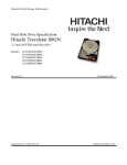
Deskstar 180 GXP
3.5 inch Ultra ATA/100 hard disk drive
Models:
IC35L030AVV207
IC35L060AVV207
IC35L090AVV207
IC35L120AVV207
IC35L180AVV207
Revision 4.2
S08-K0000-06
30 April 2003
Publication #2840
Hard disk drive specifications
Deskstar 180 GXP
3.5 inch Ultra ATA/100 hard disk drive
Models:
IC35L030AVV207
IC35L060AVV207
IC35L090AVV207
IC35L120AVV207
IC35L180AVV207
Revision 4.2
S08-K0000-06
30 April 2003
Publication #2840
1st Edition (Revision 1.0) S-08K-0000-00 (18 December 2001) Preliminary
2nd Edition (Revision 2.0) S-08K-0000-00 (18 April 2002) Preliminary
3rd Edition (Revision 2.1) S-08K-0000-00 (21 June 2002) Preliminary
4rd Edition (Revision 2.2) S-08K-0000-00 (25 July 2002) Preliminary
5th Edition (Revision 2.3) S-08K-0000-01 (01 August 2002) Preliminary
6th Edition (Revision 2.5) S-08K-0000-02 (06 August 2002) Preliminary
7th Edition (Revision 3.0) S-08K-0000-03 (16 August 2002) Preliminary
8th Edition (Revision 4.0) S-08K-0000-04 (30 September 2002) Release
9th Edition (Revision 4.1) S-08K-0000-05 (08 January 2003) Revision
10th Edition (Revision 4.2) S-08K-0000-06 (30 April 2003) Revision
The following paragraph does not apply to the United Kingdom or any country where such provisions are
inconsistent with local law: HITACHI GLOBAL STORAGE TECHNOLOGIES PROVIDES THIS PUBLICATION “AS IS” WITHOUT WARRANTY OF ANY KIND, EITHER EXPRESS OR IMPLIED, INCLUDING, BUT NOT LIMITED TO, THE IMPLIED WARRANTIES OF MERCHANTABILITY OR FITNESS
FOR A PARTICULAR PURPOSE. Some states do not allow disclaimer or express or implied warranties in certain
transactions, therefore, this statement may not apply to you.
This publication could include technical inaccuracies or typographical errors. Changes are periodically made to the
information herein; these changes will be incorporated in new editions of the publication. Hitachi may make
improvements or changes in any products or programs described in this publication at any time.
It is possible that this publication may contain reference to, or information about, Hitachi products (machines and
programs), programming, or services that are not announced in your country. Such references or information must
not be construed to mean that Hitachi intends to announce such Hitachi products, programming, or services in your
country.
Technical information about this product is available by contacting your local Hitachi Global Storage Technologies
representative or on the Internet at http://www.hgst.com
Hitachi Global Storage Technologies may have patents or pending patent applications covering subject matter in
this document. The furnishing of this document does not give you any license to these patents.
©Copyright Hitachi Globlal Storage Technologies
Note to U.S. Government Users —Documentation related to restricted rights —Use, duplication or disclosure is
subject to restrictions set forth in GSA ADP Schedule Contract with Hitachi Global Storage Technologies.
Table of contents
List of figures . . . . . . . . . . . . . . . . . . . . . . . . . . . . . . . . . . . . . . . . . . . . . . . . . . . . . . . . . . . . . . . . . . . xi
1.0
1.1
1.2
1.3
2.0
General . . . . . . . . . . . . . . . . . . . . . . . . . . . . . . . . . . . . . . . . . . . . . . . . . . . . . . . . . . . . . . . . . . . . . . 1
Glossary . . . . . . . . . . . . . . . . . . . . . . . . . . . . . . . . . . . . . . . . . . . . . . . . . . . . . . . . . . . . . . . . . . . . . . 1
General caution . . . . . . . . . . . . . . . . . . . . . . . . . . . . . . . . . . . . . . . . . . . . . . . . . . . . . . . . . . . . . . . . 1
References . . . . . . . . . . . . . . . . . . . . . . . . . . . . . . . . . . . . . . . . . . . . . . . . . . . . . . . . . . . . . . . . . . . 1
General features . . . . . . . . . . . . . . . . . . . . . . . . . . . . . . . . . . . . . . . . . . . . . . . . . . . . . . . . . . . . . 3
Part 1. Functional specification . . . . . . . . . . . . . . . . . . . . . . . . . . . . . . . . . . . . . . . . . . . . . . 5
3.0
3.1
3.2
3.3
4.0
4.1
4.2
4.3
4.4
5.0
6.0
6.1
6.2
6.3
6.4
6.5
Fixed disk subsystem description . . . . . . . . . . . . . . . . . . . . . . . . . . . . . . . . . . . . . . . . . . . . . 7
Control Electronics . . . . . . . . . . . . . . . . . . . . . . . . . . . . . . . . . . . . . . . . . . . . . . . . . . . . . . . . . . . . . 7
Head disk assembly . . . . . . . . . . . . . . . . . . . . . . . . . . . . . . . . . . . . . . . . . . . . . . . . . . . . . . . . . . . . 7
Actuator . . . . . . . . . . . . . . . . . . . . . . . . . . . . . . . . . . . . . . . . . . . . . . . . . . . . . . . . . . . . . . . . . . . . . . 7
Drive characteristics . . . . . . . . . . . . . . . . . . . . . . . . . . . . . . . . . . . . . . . . . . . . . . . . . . . . . . . . . . 9
Default logical drive parameters . . . . . . . . . . . . . . . . . . . . . . . . . . . . . . . . . . . . . . . . . . . . . . . . . . 9
Data sheet . . . . . . . . . . . . . . . . . . . . . . . . . . . . . . . . . . . . . . . . . . . . . . . . . . . . . . . . . . . . . . . . . . 10
Drive organization . . . . . . . . . . . . . . . . . . . . . . . . . . . . . . . . . . . . . . . . . . . . . . . . . . . . . . . . . . . . 11
4.3.1 Drive format . . . . . . . . . . . . . . . . . . . . . . . . . . . . . . . . . . . . . . . . . . . . . . . . . . . . . . . . . . . . 11
4.3.2 Cylinder allocation . . . . . . . . . . . . . . . . . . . . . . . . . . . . . . . . . . . . . . . . . . . . . . . . . . . . . . 11
Performance characteristics . . . . . . . . . . . . . . . . . . . . . . . . . . . . . . . . . . . . . . . . . . . . . . . . . . . 12
4.4.1 Command overhead . . . . . . . . . . . . . . . . . . . . . . . . . . . . . . . . . . . . . . . . . . . . . . . . . . . . 12
4.4.2 Mechanical positioning . . . . . . . . . . . . . . . . . . . . . . . . . . . . . . . . . . . . . . . . . . . . . . . . . . 12
4.4.3 Drive ready time . . . . . . . . . . . . . . . . . . . . . . . . . . . . . . . . . . . . . . . . . . . . . . . . . . . . . . . . 14
4.4.4 Data transfer speed . . . . . . . . . . . . . . . . . . . . . . . . . . . . . . . . . . . . . . . . . . . . . . . . . . . . . 15
4.4.5 Throughput . . . . . . . . . . . . . . . . . . . . . . . . . . . . . . . . . . . . . . . . . . . . . . . . . . . . . . . . . . . . 16
4.4.6 Operating modes . . . . . . . . . . . . . . . . . . . . . . . . . . . . . . . . . . . . . . . . . . . . . . . . . . . . . . . 17
Defect flagging strategy . . . . . . . . . . . . . . . . . . . . . . . . . . . . . . . . . . . . . . . . . . . . . . . . . . . . 19
Specification . . . . . . . . . . . . . . . . . . . . . . . . . . . . . . . . . . . . . . . . . . . . . . . . . . . . . . . . . . . . . . . 21
Electrical interface . . . . . . . . . . . . . . . . . . . . . . . . . . . . . . . . . . . . . . . . . . . . . . . . . . . . . . . . . . . 21
6.1.1 Connector location . . . . . . . . . . . . . . . . . . . . . . . . . . . . . . . . . . . . . . . . . . . . . . . . . . . . . . 21
6.1.2 Signal definition . . . . . . . . . . . . . . . . . . . . . . . . . . . . . . . . . . . . . . . . . . . . . . . . . . . . . . . . 22
6.1.3 Interface logic signal levels . . . . . . . . . . . . . . . . . . . . . . . . . . . . . . . . . . . . . . . . . . . . . . . 25
Signal timings . . . . . . . . . . . . . . . . . . . . . . . . . . . . . . . . . . . . . . . . . . . . . . . . . . . . . . . . . . . . . . . 26
6.2.1 Reset timings . . . . . . . . . . . . . . . . . . . . . . . . . . . . . . . . . . . . . . . . . . . . . . . . . . . . . . . . . . 26
6.2.2 PIO timings . . . . . . . . . . . . . . . . . . . . . . . . . . . . . . . . . . . . . . . . . . . . . . . . . . . . . . . . . . . . 27
6.2.3 Multiword DMA timings . . . . . . . . . . . . . . . . . . . . . . . . . . . . . . . . . . . . . . . . . . . . . . . . . . 29
6.2.4 Ultra DMA timings . . . . . . . . . . . . . . . . . . . . . . . . . . . . . . . . . . . . . . . . . . . . . . . . . . . . . . 30
6.2.5 Addressing of registers . . . . . . . . . . . . . . . . . . . . . . . . . . . . . . . . . . . . . . . . . . . . . . . . . . 38
6.2.6 Cabling . . . . . . . . . . . . . . . . . . . . . . . . . . . . . . . . . . . . . . . . . . . . . . . . . . . . . . . . . . . . . . . . 38
Jumper settings . . . . . . . . . . . . . . . . . . . . . . . . . . . . . . . . . . . . . . . . . . . . . . . . . . . . . . . . . . . . . . 39
6.3.1 Jumper pin location . . . . . . . . . . . . . . . . . . . . . . . . . . . . . . . . . . . . . . . . . . . . . . . . . . . . . 39
6.3.2 Jumper pin identification . . . . . . . . . . . . . . . . . . . . . . . . . . . . . . . . . . . . . . . . . . . . . . . . . 39
6.3.3 Jumper pin assignment . . . . . . . . . . . . . . . . . . . . . . . . . . . . . . . . . . . . . . . . . . . . . . . . . . 40
6.3.4 Jumper positions . . . . . . . . . . . . . . . . . . . . . . . . . . . . . . . . . . . . . . . . . . . . . . . . . . . . . . . 41
Environment . . . . . . . . . . . . . . . . . . . . . . . . . . . . . . . . . . . . . . . . . . . . . . . . . . . . . . . . . . . . . . . . 45
6.4.1 Temperature and humidity . . . . . . . . . . . . . . . . . . . . . . . . . . . . . . . . . . . . . . . . . . . . . . . 45
6.4.2 Corrosion test . . . . . . . . . . . . . . . . . . . . . . . . . . . . . . . . . . . . . . . . . . . . . . . . . . . . . . . . . . 46
DC power requirements . . . . . . . . . . . . . . . . . . . . . . . . . . . . . . . . . . . . . . . . . . . . . . . . . . . . . . . 47
Deskstar 180GXP hard disk drive specifications
v
6.5.1 Input voltage . . . . . . . . . . . . . . . . . . . . . . . . . . . . . . . . . . . . . . . . . . . . . . . . . . . . . . . . . . .
6.5.2 Power supply current (typical) . . . . . . . . . . . . . . . . . . . . . . . . . . . . . . . . . . . . . . . . . . . .
6.5.3 Power supply generated ripple at drive power connector . . . . . . . . . . . . . . . . . . . . .
6.6 Reliability . . . . . . . . . . . . . . . . . . . . . . . . . . . . . . . . . . . . . . . . . . . . . . . . . . . . . . . . . . . . . . . . . . .
6.6.1 Data integrity . . . . . . . . . . . . . . . . . . . . . . . . . . . . . . . . . . . . . . . . . . . . . . . . . . . . . . . . . . .
6.6.2 Cable noise interference . . . . . . . . . . . . . . . . . . . . . . . . . . . . . . . . . . . . . . . . . . . . . . . . .
6.6.3 Start/stop cycles . . . . . . . . . . . . . . . . . . . . . . . . . . . . . . . . . . . . . . . . . . . . . . . . . . . . . . . .
6.6.4 Preventive maintenance . . . . . . . . . . . . . . . . . . . . . . . . . . . . . . . . . . . . . . . . . . . . . . . . .
6.6.5 Data reliability . . . . . . . . . . . . . . . . . . . . . . . . . . . . . . . . . . . . . . . . . . . . . . . . . . . . . . . . . .
6.6.6 Required Power-Off Sequence . . . . . . . . . . . . . . . . . . . . . . . . . . . . . . . . . . . . . . . . . . .
6.7 Mechanical specifications . . . . . . . . . . . . . . . . . . . . . . . . . . . . . . . . . . . . . . . . . . . . . . . . . . . . .
6.7.1 Physical dimensions . . . . . . . . . . . . . . . . . . . . . . . . . . . . . . . . . . . . . . . . . . . . . . . . . . . .
6.7.2 Hole locations . . . . . . . . . . . . . . . . . . . . . . . . . . . . . . . . . . . . . . . . . . . . . . . . . . . . . . . . . .
6.7.3 Connector locations . . . . . . . . . . . . . . . . . . . . . . . . . . . . . . . . . . . . . . . . . . . . . . . . . . . . .
6.7.4 Drive mounting . . . . . . . . . . . . . . . . . . . . . . . . . . . . . . . . . . . . . . . . . . . . . . . . . . . . . . . . .
6.7.5 Heads unload and actuator lock . . . . . . . . . . . . . . . . . . . . . . . . . . . . . . . . . . . . . . . . . .
6.8 Vibration and shock . . . . . . . . . . . . . . . . . . . . . . . . . . . . . . . . . . . . . . . . . . . . . . . . . . . . . . . . . .
6.8.1 Operating vibration . . . . . . . . . . . . . . . . . . . . . . . . . . . . . . . . . . . . . . . . . . . . . . . . . . . . . .
6.8.2 Nonoperating vibration . . . . . . . . . . . . . . . . . . . . . . . . . . . . . . . . . . . . . . . . . . . . . . . . . .
6.8.3 Operating shock . . . . . . . . . . . . . . . . . . . . . . . . . . . . . . . . . . . . . . . . . . . . . . . . . . . . . . . .
6.8.4 Nonoperating shock . . . . . . . . . . . . . . . . . . . . . . . . . . . . . . . . . . . . . . . . . . . . . . . . . . . . .
6.8.5 Nonoperating Rotational shock . . . . . . . . . . . . . . . . . . . . . . . . . . . . . . . . . . . . . . . . . . .
6.9 Acoustics . . . . . . . . . . . . . . . . . . . . . . . . . . . . . . . . . . . . . . . . . . . . . . . . . . . . . . . . . . . . . . . . . . .
6.10 Identification labels . . . . . . . . . . . . . . . . . . . . . . . . . . . . . . . . . . . . . . . . . . . . . . . . . . . . . . . . . .
6.11 Safety . . . . . . . . . . . . . . . . . . . . . . . . . . . . . . . . . . . . . . . . . . . . . . . . . . . . . . . . . . . . . . . . . . . . .
6.11.1 UL and CSA standard conformity . . . . . . . . . . . . . . . . . . . . . . . . . . . . . . . . . . . . . . . .
6.11.2 German Safety Mark . . . . . . . . . . . . . . . . . . . . . . . . . . . . . . . . . . . . . . . . . . . . . . . . . . .
6.11.3 Flammability . . . . . . . . . . . . . . . . . . . . . . . . . . . . . . . . . . . . . . . . . . . . . . . . . . . . . . . . . .
6.11.4 Safe handling . . . . . . . . . . . . . . . . . . . . . . . . . . . . . . . . . . . . . . . . . . . . . . . . . . . . . . . . .
6.11.5 Environment . . . . . . . . . . . . . . . . . . . . . . . . . . . . . . . . . . . . . . . . . . . . . . . . . . . . . . . . . .
6.11.6 Secondary circuit protection . . . . . . . . . . . . . . . . . . . . . . . . . . . . . . . . . . . . . . . . . . . . .
6.12 Electromagnetic compatibility . . . . . . . . . . . . . . . . . . . . . . . . . . . . . . . . . . . . . . . . . . . . . . . . .
6.12.1 CE Mark . . . . . . . . . . . . . . . . . . . . . . . . . . . . . . . . . . . . . . . . . . . . . . . . . . . . . . . . . . . . . .
6.12.2 C-Tick Mark . . . . . . . . . . . . . . . . . . . . . . . . . . . . . . . . . . . . . . . . . . . . . . . . . . . . . . . . . . .
47
47
49
50
50
50
50
50
50
50
51
51
53
54
54
54
55
55
55
56
56
56
57
58
59
59
59
59
59
59
59
60
60
60
Part 2. Interface specification . . . . . . . . . . . . . . . . . . . . . . . . . . . . . . . . . . . . . . . . . . . . . . 61
7.0 General . . . . . . . . . . . . . . . . . . . . . . . . . . . . . . . . . . . . . . . . . . . . . . . . . . . . . . . . . . . . . . . . . . . .
7.1 Terminology . . . . . . . . . . . . . . . . . . . . . . . . . . . . . . . . . . . . . . . . . . . . . . . . . . . . . . . . . . . . . . . . .
7.2 Deviations from standard . . . . . . . . . . . . . . . . . . . . . . . . . . . . . . . . . . . . . . . . . . . . . . . . . . . . .
8.0 Registers . . . . . . . . . . . . . . . . . . . . . . . . . . . . . . . . . . . . . . . . . . . . . . . . . . . . . . . . . . . . . . . . . .
8.1 Alternate Status Register . . . . . . . . . . . . . . . . . . . . . . . . . . . . . . . . . . . . . . . . . . . . . . . . . . . . .
8.2 Command Register . . . . . . . . . . . . . . . . . . . . . . . . . . . . . . . . . . . . . . . . . . . . . . . . . . . . . . . . . .
8.3 Cylinder High Register . . . . . . . . . . . . . . . . . . . . . . . . . . . . . . . . . . . . . . . . . . . . . . . . . . . . . . .
8.4 Cylinder Low Register . . . . . . . . . . . . . . . . . . . . . . . . . . . . . . . . . . . . . . . . . . . . . . . . . . . . . . . .
8.5 Data Register . . . . . . . . . . . . . . . . . . . . . . . . . . . . . . . . . . . . . . . . . . . . . . . . . . . . . . . . . . . . . . .
8.6 Device Control Register . . . . . . . . . . . . . . . . . . . . . . . . . . . . . . . . . . . . . . . . . . . . . . . . . . . . . .
8.7 Drive Address Register . . . . . . . . . . . . . . . . . . . . . . . . . . . . . . . . . . . . . . . . . . . . . . . . . . . . . . .
8.8 Device/Head Register . . . . . . . . . . . . . . . . . . . . . . . . . . . . . . . . . . . . . . . . . . . . . . . . . . . . . . . .
8.9 Error Register . . . . . . . . . . . . . . . . . . . . . . . . . . . . . . . . . . . . . . . . . . . . . . . . . . . . . . . . . . . . . . .
8.10 Features Register . . . . . . . . . . . . . . . . . . . . . . . . . . . . . . . . . . . . . . . . . . . . . . . . . . . . . . . . . . .
8.11 Sector Count Register . . . . . . . . . . . . . . . . . . . . . . . . . . . . . . . . . . . . . . . . . . . . . . . . . . . . . . .
8.12 Sector Number Register . . . . . . . . . . . . . . . . . . . . . . . . . . . . . . . . . . . . . . . . . . . . . . . . . . . . .
8.13 Status Register . . . . . . . . . . . . . . . . . . . . . . . . . . . . . . . . . . . . . . . . . . . . . . . . . . . . . . . . . . . . .
Deskstar 180GXP hard disk drive specifications
vi
63
63
63
65
66
66
66
66
67
67
67
68
68
69
69
69
70
9.0 General operation . . . . . . . . . . . . . . . . . . . . . . . . . . . . . . . . . . . . . . . . . . . . . . . . . . . . . . . . . . 71
9.1 Reset response . . . . . . . . . . . . . . . . . . . . . . . . . . . . . . . . . . . . . . . . . . . . . . . . . . . . . . . . . . . . . 71
9.1.1 Register initialization . . . . . . . . . . . . . . . . . . . . . . . . . . . . . . . . . . . . . . . . . . . . . . . . . . . . 72
9.2 Diagnostic and reset considerations . . . . . . . . . . . . . . . . . . . . . . . . . . . . . . . . . . . . . . . . . . . . 73
9.3 Sector Addressing Mode . . . . . . . . . . . . . . . . . . . . . . . . . . . . . . . . . . . . . . . . . . . . . . . . . . . . . . 74
9.3.1 Logical CHS Addressing Mode . . . . . . . . . . . . . . . . . . . . . . . . . . . . . . . . . . . . . . . . . . . 74
9.3.2 LBA Addressing Mode . . . . . . . . . . . . . . . . . . . . . . . . . . . . . . . . . . . . . . . . . . . . . . . . . . . 74
9.4 Overlapped and queued feature . . . . . . . . . . . . . . . . . . . . . . . . . . . . . . . . . . . . . . . . . . . . . . . . 75
9.5 Power management feature . . . . . . . . . . . . . . . . . . . . . . . . . . . . . . . . . . . . . . . . . . . . . . . . . . . 76
9.5.1 Power modes . . . . . . . . . . . . . . . . . . . . . . . . . . . . . . . . . . . . . . . . . . . . . . . . . . . . . . . . . . 76
9.5.2 Power management commands . . . . . . . . . . . . . . . . . . . . . . . . . . . . . . . . . . . . . . . . . . 76
9.5.3 Standby timer . . . . . . . . . . . . . . . . . . . . . . . . . . . . . . . . . . . . . . . . . . . . . . . . . . . . . . . . . . 76
9.5.4 Interface capability for power modes . . . . . . . . . . . . . . . . . . . . . . . . . . . . . . . . . . . . . . 77
9.6 S.M.A.R.T. function . . . . . . . . . . . . . . . . . . . . . . . . . . . . . . . . . . . . . . . . . . . . . . . . . . . . . . . . . . 78
9.6.1 Attributes . . . . . . . . . . . . . . . . . . . . . . . . . . . . . . . . . . . . . . . . . . . . . . . . . . . . . . . . . . . . . . 78
9.6.2 Attribute values . . . . . . . . . . . . . . . . . . . . . . . . . . . . . . . . . . . . . . . . . . . . . . . . . . . . . . . . . 78
9.6.3 Attribute thresholds . . . . . . . . . . . . . . . . . . . . . . . . . . . . . . . . . . . . . . . . . . . . . . . . . . . . . 78
9.6.4 Threshold Exceeded Condition . . . . . . . . . . . . . . . . . . . . . . . . . . . . . . . . . . . . . . . . . . . 78
9.6.5 S.M.A.R.T. commands . . . . . . . . . . . . . . . . . . . . . . . . . . . . . . . . . . . . . . . . . . . . . . . . . . 78
9.6.6 Off-line read scanning . . . . . . . . . . . . . . . . . . . . . . . . . . . . . . . . . . . . . . . . . . . . . . . . . . . 78
9.6.7 Error log . . . . . . . . . . . . . . . . . . . . . . . . . . . . . . . . . . . . . . . . . . . . . . . . . . . . . . . . . . . . . . . 78
9.6.8 Self-test . . . . . . . . . . . . . . . . . . . . . . . . . . . . . . . . . . . . . . . . . . . . . . . . . . . . . . . . . . . . . . . 79
9.7 Security Mode Feature Set . . . . . . . . . . . . . . . . . . . . . . . . . . . . . . . . . . . . . . . . . . . . . . . . . . . . 80
9.7.1 Security mode . . . . . . . . . . . . . . . . . . . . . . . . . . . . . . . . . . . . . . . . . . . . . . . . . . . . . . . . . . 80
9.7.2 Security level . . . . . . . . . . . . . . . . . . . . . . . . . . . . . . . . . . . . . . . . . . . . . . . . . . . . . . . . . . . 80
9.7.3 Passwords . . . . . . . . . . . . . . . . . . . . . . . . . . . . . . . . . . . . . . . . . . . . . . . . . . . . . . . . . . . . . 80
9.7.4 Operation example . . . . . . . . . . . . . . . . . . . . . . . . . . . . . . . . . . . . . . . . . . . . . . . . . . . . . . 81
9.7.5 Command table . . . . . . . . . . . . . . . . . . . . . . . . . . . . . . . . . . . . . . . . . . . . . . . . . . . . . . . . 84
9.8 Host Protected Area Function . . . . . . . . . . . . . . . . . . . . . . . . . . . . . . . . . . . . . . . . . . . . . . . . . . 86
9.8.1 Example for operation (in LBA mode) . . . . . . . . . . . . . . . . . . . . . . . . . . . . . . . . . . . . . . 86
9.8.2 Security extensions . . . . . . . . . . . . . . . . . . . . . . . . . . . . . . . . . . . . . . . . . . . . . . . . . . . . . 87
9.9 Seek Overlap . . . . . . . . . . . . . . . . . . . . . . . . . . . . . . . . . . . . . . . . . . . . . . . . . . . . . . . . . . . . . . . . 88
9.10 Write cache function . . . . . . . . . . . . . . . . . . . . . . . . . . . . . . . . . . . . . . . . . . . . . . . . . . . . . . . . . 89
9.11 Reassign function . . . . . . . . . . . . . . . . . . . . . . . . . . . . . . . . . . . . . . . . . . . . . . . . . . . . . . . . . . . 89
9.11.1 Auto Reassign function . . . . . . . . . . . . . . . . . . . . . . . . . . . . . . . . . . . . . . . . . . . . . . . . . 89
9.12 Power-Up In Standby feature set . . . . . . . . . . . . . . . . . . . . . . . . . . . . . . . . . . . . . . . . . . . . . . 90
9.13 Advanced Power Management feature set (APM) . . . . . . . . . . . . . . . . . . . . . . . . . . . . . . . 90
9.14 Automatic Acoustic Management feature set (AAM) . . . . . . . . . . . . . . . . . . . . . . . . . . . . . 91
9.15 Address Offset Feature . . . . . . . . . . . . . . . . . . . . . . . . . . . . . . . . . . . . . . . . . . . . . . . . . . . . . . 91
9.15.1 Enable/Disable Address Offset Mode . . . . . . . . . . . . . . . . . . . . . . . . . . . . . . . . . . . . . 91
9.15.2 Identify Device Data . . . . . . . . . . . . . . . . . . . . . . . . . . . . . . . . . . . . . . . . . . . . . . . . . . . . 92
9.15.3 Exceptions in Address Offset Mode . . . . . . . . . . . . . . . . . . . . . . . . . . . . . . . . . . . . . . 92
9.16 48-bit Address Feature Set . . . . . . . . . . . . . . . . . . . . . . . . . . . . . . . . . . . . . . . . . . . . . . . . . . 93
10.0 Command Protocol . . . . . . . . . . . . . . . . . . . . . . . . . . . . . . . . . . . . . . . . . . . . . . . . . . . . . . . . 95
10.1 PIO Data In commands . . . . . . . . . . . . . . . . . . . . . . . . . . . . . . . . . . . . . . . . . . . . . . . . . . . . . . 96
10.2 PIO Data Out commands . . . . . . . . . . . . . . . . . . . . . . . . . . . . . . . . . . . . . . . . . . . . . . . . . . . . 98
10.3 Non-data commands . . . . . . . . . . . . . . . . . . . . . . . . . . . . . . . . . . . . . . . . . . . . . . . . . . . . . . . 100
10.4 DMA commands . . . . . . . . . . . . . . . . . . . . . . . . . . . . . . . . . . . . . . . . . . . . . . . . . . . . . . . . . . . 102
10.5 DMA queued commands . . . . . . . . . . . . . . . . . . . . . . . . . . . . . . . . . . . . . . . . . . . . . . . . . . . . 103
11.0 Command descriptions . . . . . . . . . . . . . . . . . . . . . . . . . . . . . . . . . . . . . . . . . . . . . . . . . . . 105
11.1 Check Power Mode (E5h/98h) . . . . . . . . . . . . . . . . . . . . . . . . . . . . . . . . . . . . . . . . . . . . . . . 109
11.2 Device Configuration Overlay (B1h) . . . . . . . . . . . . . . . . . . . . . . . . . . . . . . . . . . . . . . . . . . 110
11.2.1 DEVICE CONFIGURATION RESTORE (subcommand C0h) . . . . . . . . . . . . . . . 110
11.2.2 DEVICE CONFIGURATION FREEZE LOCK (subcommand C1h) . . . . . . . . . . . 111
11.2.3 DEVICE CONFIGURATION IDENTIFY (subcommand C2h) . . . . . . . . . . . . . . . . 111
11.2.4 DEVICE CONFIGURATION SET (subcommand C3h) . . . . . . . . . . . . . . . . . . . . . 111
Deskstar 180GXP hard disk drive specifications
vii
11.3 Execute Device Diagnostic (90h) . . . . . . . . . . . . . . . . . . . . . . . . . . . . . . . . . . . . . . . . . . . . .
11.4 Flush Cache (E7h) . . . . . . . . . . . . . . . . . . . . . . . . . . . . . . . . . . . . . . . . . . . . . . . . . . . . . . . . .
11.5 Flush Cache Ext (EAh) . . . . . . . . . . . . . . . . . . . . . . . . . . . . . . . . . . . . . . . . . . . . . . . . . . . . .
11.6 Format Track (50h) . . . . . . . . . . . . . . . . . . . . . . . . . . . . . . . . . . . . . . . . . . . . . . . . . . . . . . . .
11.7 Format Unit (F7h) . . . . . . . . . . . . . . . . . . . . . . . . . . . . . . . . . . . . . . . . . . . . . . . . . . . . . . . . . .
11.8 Identify Device (ECh) . . . . . . . . . . . . . . . . . . . . . . . . . . . . . . . . . . . . . . . . . . . . . . . . . . . . . . .
11.9 Idle (E3h/97h) . . . . . . . . . . . . . . . . . . . . . . . . . . . . . . . . . . . . . . . . . . . . . . . . . . . . . . . . . . . . .
11.10 Idle Immediate (E1h/95h) . . . . . . . . . . . . . . . . . . . . . . . . . . . . . . . . . . . . . . . . . . . . . . . . . .
11.11 Initialize Device Parameters (91h) . . . . . . . . . . . . . . . . . . . . . . . . . . . . . . . . . . . . . . . . . . .
11.12 NOP (00h) . . . . . . . . . . . . . . . . . . . . . . . . . . . . . . . . . . . . . . . . . . . . . . . . . . . . . . . . . . . . . . .
11.13 Read Buffer (E4h) . . . . . . . . . . . . . . . . . . . . . . . . . . . . . . . . . . . . . . . . . . . . . . . . . . . . . . . .
11.14 Read DMA (C8h/C9h) . . . . . . . . . . . . . . . . . . . . . . . . . . . . . . . . . . . . . . . . . . . . . . . . . . . . .
11.15 Read DMA Ext (25h) . . . . . . . . . . . . . . . . . . . . . . . . . . . . . . . . . . . . . . . . . . . . . . . . . . . . . .
11.16 Read DMA Queued (C7h) . . . . . . . . . . . . . . . . . . . . . . . . . . . . . . . . . . . . . . . . . . . . . . . . . .
11.17 Read DMA Queued Ext (26h) . . . . . . . . . . . . . . . . . . . . . . . . . . . . . . . . . . . . . . . . . . . . . .
11.18 Read Log Ext (2Fh) . . . . . . . . . . . . . . . . . . . . . . . . . . . . . . . . . . . . . . . . . . . . . . . . . . . . . . .
11.18.1 General Purpose Log Directory . . . . . . . . . . . . . . . . . . . . . . . . . . . . . . . . . . . . . . . .
11.18.2 Extended Comprehensive SMART Error log . . . . . . . . . . . . . . . . . . . . . . . . . . . . .
11.18.3 Extended Self-test log sector . . . . . . . . . . . . . . . . . . . . . . . . . . . . . . . . . . . . . . . . . .
11.19 Read Long (22h/23h) . . . . . . . . . . . . . . . . . . . . . . . . . . . . . . . . . . . . . . . . . . . . . . . . . . . . . .
11.20 Read Multiple (C4h) . . . . . . . . . . . . . . . . . . . . . . . . . . . . . . . . . . . . . . . . . . . . . . . . . . . . . . .
11.21 Read Multiple Ext (29h) . . . . . . . . . . . . . . . . . . . . . . . . . . . . . . . . . . . . . . . . . . . . . . . . . . . .
11.22 Read Native Max Address (F8h) . . . . . . . . . . . . . . . . . . . . . . . . . . . . . . . . . . . . . . . . . . . .
11.23 Read Native Max Address Ext (27h) . . . . . . . . . . . . . . . . . . . . . . . . . . . . . . . . . . . . . . . .
11.24 Read Sector(s) (20h/21h) . . . . . . . . . . . . . . . . . . . . . . . . . . . . . . . . . . . . . . . . . . . . . . . . . .
11.25 Read Sector(s) Ext (24h) . . . . . . . . . . . . . . . . . . . . . . . . . . . . . . . . . . . . . . . . . . . . . . . . . .
11.26 Read Verify Sector(s) (40h/41h) . . . . . . . . . . . . . . . . . . . . . . . . . . . . . . . . . . . . . . . . . . . .
11.27 Read Verify Sector(s) Ext (42h) . . . . . . . . . . . . . . . . . . . . . . . . . . . . . . . . . . . . . . . . . . . . .
11.28 Recalibrate (1xh) . . . . . . . . . . . . . . . . . . . . . . . . . . . . . . . . . . . . . . . . . . . . . . . . . . . . . . . . .
11.29 Security Disable Password (F6h) . . . . . . . . . . . . . . . . . . . . . . . . . . . . . . . . . . . . . . . . . . .
11.30 Security Erase Prepare (F3h) . . . . . . . . . . . . . . . . . . . . . . . . . . . . . . . . . . . . . . . . . . . . . . .
11.31 Security Erase Unit (F4h) . . . . . . . . . . . . . . . . . . . . . . . . . . . . . . . . . . . . . . . . . . . . . . . . . .
11.32 Security Freeze Lock (F5h) . . . . . . . . . . . . . . . . . . . . . . . . . . . . . . . . . . . . . . . . . . . . . . . .
11.33 Security Set Password (F1h) . . . . . . . . . . . . . . . . . . . . . . . . . . . . . . . . . . . . . . . . . . . . . . .
11.34 Security Unlock (F2h) . . . . . . . . . . . . . . . . . . . . . . . . . . . . . . . . . . . . . . . . . . . . . . . . . . . . .
11.35 Seek (7xh) . . . . . . . . . . . . . . . . . . . . . . . . . . . . . . . . . . . . . . . . . . . . . . . . . . . . . . . . . . . . . . .
11.36 Service (A2h) . . . . . . . . . . . . . . . . . . . . . . . . . . . . . . . . . . . . . . . . . . . . . . . . . . . . . . . . . . . .
11.37 Set Features (EFh) . . . . . . . . . . . . . . . . . . . . . . . . . . . . . . . . . . . . . . . . . . . . . . . . . . . . . . . .
11.37.1 Set Transfer mode . . . . . . . . . . . . . . . . . . . . . . . . . . . . . . . . . . . . . . . . . . . . . . . . . . .
11.37.2 Write Cache . . . . . . . . . . . . . . . . . . . . . . . . . . . . . . . . . . . . . . . . . . . . . . . . . . . . . . . .
11.37.3 Advanced Power Management . . . . . . . . . . . . . . . . . . . . . . . . . . . . . . . . . . . . . . . .
11.37.4 Automatic Acoustic Management . . . . . . . . . . . . . . . . . . . . . . . . . . . . . . . . . . . . . .
11.38 Set Max Address (F9h) . . . . . . . . . . . . . . . . . . . . . . . . . . . . . . . . . . . . . . . . . . . . . . . . . . . .
11.38.1 Set Max Set Password (Feature = 01h) . . . . . . . . . . . . . . . . . . . . . . . . . . . . . . . . .
11.38.2 Set Max Lock (Feature = 02h) . . . . . . . . . . . . . . . . . . . . . . . . . . . . . . . . . . . . . . . . .
11.38.3 Set Max Unlock (Feature = 03h) . . . . . . . . . . . . . . . . . . . . . . . . . . . . . . . . . . . . . . .
11.38.4 Set Max Freeze Lock (Feature = 04h) . . . . . . . . . . . . . . . . . . . . . . . . . . . . . . . . . .
11.39 Set Max Address Ext (37h) . . . . . . . . . . . . . . . . . . . . . . . . . . . . . . . . . . . . . . . . . . . . . . . . .
11.40 Set Multiple (C6h) . . . . . . . . . . . . . . . . . . . . . . . . . . . . . . . . . . . . . . . . . . . . . . . . . . . . . . . . .
11.41 Sleep (E6h/99h) . . . . . . . . . . . . . . . . . . . . . . . . . . . . . . . . . . . . . . . . . . . . . . . . . . . . . . . . . .
11.42 S.M.A.R.T. Function Set (B0h) . . . . . . . . . . . . . . . . . . . . . . . . . . . . . . . . . . . . . . . . . . . . . .
11.42.1 S.M.A.R.T. Subcommand . . . . . . . . . . . . . . . . . . . . . . . . . . . . . . . . . . . . . . . . . . . . .
11.42.2 Device Attributes Data Structure . . . . . . . . . . . . . . . . . . . . . . . . . . . . . . . . . . . . . . .
11.42.3 Device Attribute Thresholds Data Structure . . . . . . . . . . . . . . . . . . . . . . . . . . . . .
11.42.4 SMART Log Directory . . . . . . . . . . . . . . . . . . . . . . . . . . . . . . . . . . . . . . . . . . . . . . . .
11.42.5 SMART summary error log sector . . . . . . . . . . . . . . . . . . . . . . . . . . . . . . . . . . . . . .
Deskstar 180GXP hard disk drive specifications
viii
114
115
116
117
119
120
127
128
129
130
131
132
134
136
138
140
141
142
145
147
149
151
153
154
155
157
159
161
163
164
165
166
168
169
171
173
174
175
176
176
176
177
179
181
182
183
184
185
187
188
189
190
194
198
199
200
11.42.6 Self-test log data structure . . . . . . . . . . . . . . . . . . . . . . . . . . . . . . . . . . . . . . . . . . . .
11.42.7 Error reporting . . . . . . . . . . . . . . . . . . . . . . . . . . . . . . . . . . . . . . . . . . . . . . . . . . . . . .
11.43 Standby (E2h/96h) . . . . . . . . . . . . . . . . . . . . . . . . . . . . . . . . . . . . . . . . . . . . . . . . . . . . . . . .
11.44 Standby Immediate (E0h/94h) . . . . . . . . . . . . . . . . . . . . . . . . . . . . . . . . . . . . . . . . . . . . . .
11.45 Write Buffer (E8h) . . . . . . . . . . . . . . . . . . . . . . . . . . . . . . . . . . . . . . . . . . . . . . . . . . . . . . . . .
11.46 Write DMA (CAh/CBh) . . . . . . . . . . . . . . . . . . . . . . . . . . . . . . . . . . . . . . . . . . . . . . . . . . . . .
11.47 Write DMA Ext (35h) . . . . . . . . . . . . . . . . . . . . . . . . . . . . . . . . . . . . . . . . . . . . . . . . . . . . . .
11.48 Write DMA Queued (CAh/CBh) . . . . . . . . . . . . . . . . . . . . . . . . . . . . . . . . . . . . . . . . . . . . .
11.49 Write DMA Queued Ext (36h) . . . . . . . . . . . . . . . . . . . . . . . . . . . . . . . . . . . . . . . . . . . . . . .
11.50 Write Log Ext (3Fh) . . . . . . . . . . . . . . . . . . . . . . . . . . . . . . . . . . . . . . . . . . . . . . . . . . . . . . .
11.51 Write Long (32h/33h) . . . . . . . . . . . . . . . . . . . . . . . . . . . . . . . . . . . . . . . . . . . . . . . . . . . . . .
11.52 Write Multiple (C5h) . . . . . . . . . . . . . . . . . . . . . . . . . . . . . . . . . . . . . . . . . . . . . . . . . . . . . . .
11.53 Write Multiple Ext (39h) . . . . . . . . . . . . . . . . . . . . . . . . . . . . . . . . . . . . . . . . . . . . . . . . . . . .
11.54 Write Sector(s) (30h/31h) . . . . . . . . . . . . . . . . . . . . . . . . . . . . . . . . . . . . . . . . . . . . . . . . . .
11.55 Write Sector(s) Ext (34h) . . . . . . . . . . . . . . . . . . . . . . . . . . . . . . . . . . . . . . . . . . . . . . . . . . .
12.0 Timings . . . . . . . . . . . . . . . . . . . . . . . . . . . . . . . . . . . . . . . . . . . . . . . . . . . . . . . . . . . . . . . . .
203
204
205
207
208
209
211
213
215
217
219
221
223
225
227
229
Index . . . . . . . . . . . . . . . . . . . . . . . . . . . . . . . . . . . . . . . . . . . . . . . . . . . . . . . . . . . . . . . . . . . . . . . . . 231
Deskstar 180GXP hard disk drive specifications
ix
This page intentionally left blank.
List of figures
Figure 1. Formatted capacity . . . . . . . . . . . . . . . . . . . . . . . . . . . . . . . . . . . . . . . . . . . . . . . . . . . . . . . . 9
Figure 2. Mechanical positioning performance . . . . . . . . . . . . . . . . . . . . . . . . . . . . . . . . . . . . . . . 10
Figure 3. Cylinder allocation . . . . . . . . . . . . . . . . . . . . . . . . . . . . . . . . . . . . . . . . . . . . . . . . . . . . . . . 11
Figure 4. Command overhead . . . . . . . . . . . . . . . . . . . . . . . . . . . . . . . . . . . . . . . . . . . . . . . . . . . . 12
Figure 5. Mechanical positioning performance . . . . . . . . . . . . . . . . . . . . . . . . . . . . . . . . . . . . . . . 12
Figure 6. Full stroke seek time . . . . . . . . . . . . . . . . . . . . . . . . . . . . . . . . . . . . . . . . . . . . . . . . . . . . . 13
Figure 7. Head switch time . . . . . . . . . . . . . . . . . . . . . . . . . . . . . . . . . . . . . . . . . . . . . . . . . . . . . . . . 13
Figure 8. Cylinder switch time . . . . . . . . . . . . . . . . . . . . . . . . . . . . . . . . . . . . . . . . . . . . . . . . . . . . . 14
Figure 9. Single Track Seek Time . . . . . . . . . . . . . . . . . . . . . . . . . . . . . . . . . . . . . . . . . . . . . . . . . . 14
Figure 10. Latency Time . . . . . . . . . . . . . . . . . . . . . . . . . . . . . . . . . . . . . . . . . . . . . . . . . . . . . . . . . . 14
Figure 11. Drive ready time . . . . . . . . . . . . . . . . . . . . . . . . . . . . . . . . . . . . . . . . . . . . . . . . . . . . . . . . 14
Figure 12. Data transfer speed . . . . . . . . . . . . . . . . . . . . . . . . . . . . . . . . . . . . . . . . . . . . . . . . . . . . . 15
Figure 13. Simple Sequential Access performance . . . . . . . . . . . . . . . . . . . . . . . . . . . . . . . . . . . 16
Figure 14. Random Access Performance . . . . . . . . . . . . . . . . . . . . . . . . . . . . . . . . . . . . . . . . . . . . 16
Figure 15. Mode transition times . . . . . . . . . . . . . . . . . . . . . . . . . . . . . . . . . . . . . . . . . . . . . . . . . . . 17
Figure 16. PList physical format . . . . . . . . . . . . . . . . . . . . . . . . . . . . . . . . . . . . . . . . . . . . . . . . . . . . 19
Figure 17. Connector location (2- and 3-disk model shown) . . . . . . . . . . . . . . . . . . . . . . . . . . . . 21
Figure 18. Power connector pin assignments . . . . . . . . . . . . . . . . . . . . . . . . . . . . . . . . . . . . . . . . 21
Figure 19. Table of signals . . . . . . . . . . . . . . . . . . . . . . . . . . . . . . . . . . . . . . . . . . . . . . . . . . . . . . . . 22
Figure 20. Signal special definitions for Ultra DMA . . . . . . . . . . . . . . . . . . . . . . . . . . . . . . . . . . . . 22
Figure 21. System reset timing chart . . . . . . . . . . . . . . . . . . . . . . . . . . . . . . . . . . . . . . . . . . . . . . . . 26
Figure 22. System reset timing . . . . . . . . . . . . . . . . . . . . . . . . . . . . . . . . . . . . . . . . . . . . . . . . . . . . . 26
Figure 23. PIO cycle timings chart . . . . . . . . . . . . . . . . . . . . . . . . . . . . . . . . . . . . . . . . . . . . . . . . . . 27
Figure 24. PIO cycle timings . . . . . . . . . . . . . . . . . . . . . . . . . . . . . . . . . . . . . . . . . . . . . . . . . . . . . . . 27
Figure 25. Multiword DMA cycle timing chart . . . . . . . . . . . . . . . . . . . . . . . . . . . . . . . . . . . . . . . . . 29
Figure 26. Multiword DMA cycle timings . . . . . . . . . . . . . . . . . . . . . . . . . . . . . . . . . . . . . . . . . . . . . 29
Figure 27. Ultra DMA cycle timing chart (Initiating Read) . . . . . . . . . . . . . . . . . . . . . . . . . . . . . . 30
Figure 28. Ultra DMA cycle timings (Initiating Read) . . . . . . . . . . . . . . . . . . . . . . . . . . . . . . . . . . 30
Figure 29. Ultra DMA cycle timing chart (Host pausing Read) . . . . . . . . . . . . . . . . . . . . . . . . . . 31
Figure 30. Ultra DMA cycle timings (Host pausing Read) . . . . . . . . . . . . . . . . . . . . . . . . . . . . . . 31
Figure 31. Ultra DMA cycle timing chart (Host terminating Read) . . . . . . . . . . . . . . . . . . . . . . . 32
Figure 32. Ultra DMA cycle timings (Host terminating Read) . . . . . . . . . . . . . . . . . . . . . . . . . . . 32
Figure 33. Ultra DMA cycle timing chart (Device terminating Read) . . . . . . . . . . . . . . . . . . . . . 33
Figure 34. Ultra DMA cycle timings (Device Terminating Read) . . . . . . . . . . . . . . . . . . . . . . . . . 33
Figure 35. Ultra DMA cycle timing chart (Initiating Write) . . . . . . . . . . . . . . . . . . . . . . . . . . . . . . 34
Figure 36. Ultra DMA cycle timings (Initiating Write) . . . . . . . . . . . . . . . . . . . . . . . . . . . . . . . . . . 34
Figure 37. Ultra DMA cycle timing chart (Device Pausing Write) . . . . . . . . . . . . . . . . . . . . . . . . 35
Figure 38. Ultra DMA cycle timings (Device Pausing Write) . . . . . . . . . . . . . . . . . . . . . . . . . . . . 35
Figure 39. Ultra DMA cycle timing chart (Device Terminating Write) . . . . . . . . . . . . . . . . . . . . . 36
Figure 40. Ultra DMA cycle timings (Device terminating Write) . . . . . . . . . . . . . . . . . . . . . . . . . 36
Figure 41. Ultra DMA cycle timing chart (Host Terminating Write) . . . . . . . . . . . . . . . . . . . . . . . 37
Figure 42. Ultra DMA cycle timings (Host Terminating Write) . . . . . . . . . . . . . . . . . . . . . . . . . . . 37
Figure 43. I/O address map . . . . . . . . . . . . . . . . . . . . . . . . . . . . . . . . . . . . . . . . . . . . . . . . . . . . . . . 38
Figure 44. Jumper pin location (2- and 3-disk model shown) . . . . . . . . . . . . . . . . . . . . . . . . . . . 39
Figure 45. Jumper pin identification (2- and 3-disk model shown) . . . . . . . . . . . . . . . . . . . . . . . 39
Figure 46. Jumper pin assignment . . . . . . . . . . . . . . . . . . . . . . . . . . . . . . . . . . . . . . . . . . . . . . . . . 40
Figure 47. Jumper positions for normal use . . . . . . . . . . . . . . . . . . . . . . . . . . . . . . . . . . . . . . . . . . 41
Figure 48. Jumper positions for 15 logical head default . . . . . . . . . . . . . . . . . . . . . . . . . . . . . . . 42
Figure 49. Jumper positions for capacity clip to 2GB/32GB . . . . . . . . . . . . . . . . . . . . . . . . . . . . 43
Figure 50. Jumper settings for Disabling Auto Spin . . . . . . . . . . . . . . . . . . . . . . . . . . . . . . . . . . . 44
Figure 51. Temperature and humidity . . . . . . . . . . . . . . . . . . . . . . . . . . . . . . . . . . . . . . . . . . . . . . . 45
Figure 52. Limits of temperature and humidity . . . . . . . . . . . . . . . . . . . . . . . . . . . . . . . . . . . . . . . . 46
Deskstar 180GXP hard disk drive specifications
xi
Figure 53. Input voltage . . . . . . . . . . . . . . . . . . . . . . . . . . . . . . . . . . . . . . . . . . . . . . . . . . . . . . . . . . . 47
Figure 54. Power supply current of 180 GB models . . . . . . . . . . . . . . . . . . . . . . . . . . . . . . . . . . . 47
Figure 55. Power supply current of 80 GB and 120 GB models . . . . . . . . . . . . . . . . . . . . . . . . . 48
Figure 56. Power supply current of 60 GB, 40GB, and 30 GB models . . . . . . . . . . . . . . . . . . . 48
Figure 57. Power supply generated ripple at drive power connector . . . . . . . . . . . . . . . . . . . . . 49
Figure 58. Top and side views of 80 GB - 180 GB models with mechanical dimensions . . . . 51
Figure 59. Bottom and side views of 30GB - 60GB models with breather hole and
mounting hole locations . . . . . . . . . . . . . . . . . . . . . . . . . . . . . . . . . . . . . . . . . . . . . . . . . . . . . . . 52
Figure 60. Physical Dimensions . . . . . . . . . . . . . . . . . . . . . . . . . . . . . . . . . . . . . . . . . . . . . . . . . . . . 52
Figure 61. Mounting hole locations . . . . . . . . . . . . . . . . . . . . . . . . . . . . . . . . . . . . . . . . . . . . . . . . . 53
Figure 62. Connector locations . . . . . . . . . . . . . . . . . . . . . . . . . . . . . . . . . . . . . . . . . . . . . . . . . . . . 54
Figure 63. Random vibration PSD profile break points (operating) . . . . . . . . . . . . . . . . . . . . . . 55
Figure 64. Random vibration PSD profile break points (nonoperating) . . . . . . . . . . . . . . . . . . . 55
Figure 65. Sinusoidal shock wave . . . . . . . . . . . . . . . . . . . . . . . . . . . . . . . . . . . . . . . . . . . . . . . . . . 56
Figure 66. Rotational Shock . . . . . . . . . . . . . . . . . . . . . . . . . . . . . . . . . . . . . . . . . . . . . . . . . . . . . . . 56
Figure 67. Sound power levels . . . . . . . . . . . . . . . . . . . . . . . . . . . . . . . . . . . . . . . . . . . . . . . . . . . . . 57
Figure 68. Register Set . . . . . . . . . . . . . . . . . . . . . . . . . . . . . . . . . . . . . . . . . . . . . . . . . . . . . . . . . . . 65
Figure 69. Alternate Status Register . . . . . . . . . . . . . . . . . . . . . . . . . . . . . . . . . . . . . . . . . . . . . . . . 66
Figure 70. Device Control Register . . . . . . . . . . . . . . . . . . . . . . . . . . . . . . . . . . . . . . . . . . . . . . . . . 67
Figure 71. Drive Address Register . . . . . . . . . . . . . . . . . . . . . . . . . . . . . . . . . . . . . . . . . . . . . . . . . . 67
Figure 72. Device/Head Register . . . . . . . . . . . . . . . . . . . . . . . . . . . . . . . . . . . . . . . . . . . . . . . . . . . 68
Figure 73. Error Register . . . . . . . . . . . . . . . . . . . . . . . . . . . . . . . . . . . . . . . . . . . . . . . . . . . . . . . . . . 68
Figure 74. Status Register . . . . . . . . . . . . . . . . . . . . . . . . . . . . . . . . . . . . . . . . . . . . . . . . . . . . . . . . 70
Figure 75. Reset Response Table . . . . . . . . . . . . . . . . . . . . . . . . . . . . . . . . . . . . . . . . . . . . . . . . . . 71
Figure 76. Default Register Values . . . . . . . . . . . . . . . . . . . . . . . . . . . . . . . . . . . . . . . . . . . . . . . . . 72
Figure 77. Diagnostic Codes . . . . . . . . . . . . . . . . . . . . . . . . . . . . . . . . . . . . . . . . . . . . . . . . . . . . . . 72
Figure 78. Reset error register values . . . . . . . . . . . . . . . . . . . . . . . . . . . . . . . . . . . . . . . . . . . . . . . 73
Figure 79. Power conditions . . . . . . . . . . . . . . . . . . . . . . . . . . . . . . . . . . . . . . . . . . . . . . . . . . . . . . . 77
Figure 80. Initial Setting . . . . . . . . . . . . . . . . . . . . . . . . . . . . . . . . . . . . . . . . . . . . . . . . . . . . . . . . . . . 81
Figure 81. Usual Operation . . . . . . . . . . . . . . . . . . . . . . . . . . . . . . . . . . . . . . . . . . . . . . . . . . . . . . . . 82
Figure 82. Password Lost . . . . . . . . . . . . . . . . . . . . . . . . . . . . . . . . . . . . . . . . . . . . . . . . . . . . . . . . . 83
Figure 83. Command table for device lock operation (part 1 of 2) . . . . . . . . . . . . . . . . . . . . . . . 84
Figure 84. Command table for device lock operation (part 2 of 2) . . . . . . . . . . . . . . . . . . . . . . 85
Figure 85. Seek overlap . . . . . . . . . . . . . . . . . . . . . . . . . . . . . . . . . . . . . . . . . . . . . . . . . . . . . . . . . . 88
Figure 86. Device address map before and after Set Feature . . . . . . . . . . . . . . . . . . . . . . . . . . 92
Figure 87. Command set (1 of 2) . . . . . . . . . . . . . . . . . . . . . . . . . . . . . . . . . . . . . . . . . . . . . . . . . . 105
Figure 88. Command set (2 of 2) . . . . . . . . . . . . . . . . . . . . . . . . . . . . . . . . . . . . . . . . . . . . . . . . . . 106
Figure 89. Command set (Subcommands) . . . . . . . . . . . . . . . . . . . . . . . . . . . . . . . . . . . . . . . . . 107
Figure 90. Check Power Mode Command (E5h/98h) . . . . . . . . . . . . . . . . . . . . . . . . . . . . . . . . . 109
Figure 91. Device Configuration Overlay Command (B1h) . . . . . . . . . . . . . . . . . . . . . . . . . . . . 110
Figure 92. Device Configuration Overlay Features register values . . . . . . . . . . . . . . . . . . . . . 110
Figure 93. Device Configuration Overlay Data structure . . . . . . . . . . . . . . . . . . . . . . . . . . . . . . 112
Figure 94. DCO error information definition . . . . . . . . . . . . . . . . . . . . . . . . . . . . . . . . . . . . . . . . . 113
Figure 95. Execute Device Diagnostic Command (90h) . . . . . . . . . . . . . . . . . . . . . . . . . . . . . . 114
Figure 96. Flush Cache Command (E7h) . . . . . . . . . . . . . . . . . . . . . . . . . . . . . . . . . . . . . . . . . . . 115
Figure 97. Flush Cache Ext Command (EAh) . . . . . . . . . . . . . . . . . . . . . . . . . . . . . . . . . . . . . . . 116
Figure 98. Format Track Command (50h) . . . . . . . . . . . . . . . . . . . . . . . . . . . . . . . . . . . . . . . . . . 117
Figure 99. Format Unit Command (F7h) . . . . . . . . . . . . . . . . . . . . . . . . . . . . . . . . . . . . . . . . . . . . 119
Figure 100. Identify Device Command (ECh) . . . . . . . . . . . . . . . . . . . . . . . . . . . . . . . . . . . . . . . 120
Figure 101. Identify Device Information (part 1 of 6) . . . . . . . . . . . . . . . . . . . . . . . . . . . . . . . . . 121
Figure 102. Identify Device Information (part 2 of 6) . . . . . . . . . . . . . . . . . . . . . . . . . . . . . . . . . . 122
Figure 103. Identify Device Information (part 3 of 6) . . . . . . . . . . . . . . . . . . . . . . . . . . . . . . . . . . 123
Figure 104. Identify Device Information (part 4 of 6) . . . . . . . . . . . . . . . . . . . . . . . . . . . . . . . . . . 124
Figure 105. Identify Device Information (part 5 of 6) . . . . . . . . . . . . . . . . . . . . . . . . . . . . . . . . . . 125
Figure 106. Identify Device Information (part 6 of 6) . . . . . . . . . . . . . . . . . . . . . . . . . . . . . . . . . . 126
Figure 107. Idle Command (E3h/97h) . . . . . . . . . . . . . . . . . . . . . . . . . . . . . . . . . . . . . . . . . . . . . . 127
Deskstar 180GXP hard disk drive specifications
xii
Figure 108. Idle Immediate Command (E1h/95h) . . . . . . . . . . . . . . . . . . . . . . . . . . . . . . . . . . . .
Figure 109. Initialize Device Parameters Command (91h) . . . . . . . . . . . . . . . . . . . . . . . . . . . .
Figure 110. NOP Command (00h) . . . . . . . . . . . . . . . . . . . . . . . . . . . . . . . . . . . . . . . . . . . . . . . . .
Figure 111. Read Buffer Command (E4h) . . . . . . . . . . . . . . . . . . . . . . . . . . . . . . . . . . . . . . . . . .
Figure 112. Read DMA Command (C8h/C9h) . . . . . . . . . . . . . . . . . . . . . . . . . . . . . . . . . . . . . . .
Figure 113. Read DMA Ext Command (25h) . . . . . . . . . . . . . . . . . . . . . . . . . . . . . . . . . . . . . . . .
Figure 114. Read DMA Queued Command (C7h) . . . . . . . . . . . . . . . . . . . . . . . . . . . . . . . . . . .
Figure 115. Read DMA Queued Ext Command (26h) . . . . . . . . . . . . . . . . . . . . . . . . . . . . . . . .
Figure 116. Read Log Ext Command (2Fh) . . . . . . . . . . . . . . . . . . . . . . . . . . . . . . . . . . . . . . . . .
Figure 117. Log Address Definition . . . . . . . . . . . . . . . . . . . . . . . . . . . . . . . . . . . . . . . . . . . . . . . .
Figure 118. General Purpose Log Directory . . . . . . . . . . . . . . . . . . . . . . . . . . . . . . . . . . . . . . . .
Figure 119. Extended Comprehensive SMART Error Log . . . . . . . . . . . . . . . . . . . . . . . . . . . . .
Figure 120. Extended Error log data structure . . . . . . . . . . . . . . . . . . . . . . . . . . . . . . . . . . . . . .
Figure 121. Command data structure . . . . . . . . . . . . . . . . . . . . . . . . . . . . . . . . . . . . . . . . . . . . .
Figure 122. Error data structure . . . . . . . . . . . . . . . . . . . . . . . . . . . . . . . . . . . . . . . . . . . . . . . . . .
Figure 123. Extended Self-test log data structure . . . . . . . . . . . . . . . . . . . . . . . . . . . . . . . . . . .
Figure 124. Extended Self-test log descriptor entry . . . . . . . . . . . . . . . . . . . . . . . . . . . . . . . . . .
Figure 125. Read Long Command (22h/23h) . . . . . . . . . . . . . . . . . . . . . . . . . . . . . . . . . . . . . . .
Figure 126. Read Multiple Command (C4h) . . . . . . . . . . . . . . . . . . . . . . . . . . . . . . . . . . . . . . . .
Figure 127. Read Multiple Ext (29h) . . . . . . . . . . . . . . . . . . . . . . . . . . . . . . . . . . . . . . . . . . . . . . .
Figure 128. Read Native Max Address (F8h) . . . . . . . . . . . . . . . . . . . . . . . . . . . . . . . . . . . . . . .
Figure 129. Read Native Max Address Ext (F8h) . . . . . . . . . . . . . . . . . . . . . . . . . . . . . . . . . . . .
Figure 130. Read Sector(s) Command (20h/21h) . . . . . . . . . . . . . . . . . . . . . . . . . . . . . . . . . . . .
Figure 131. Read Sector(s) Ext Command (24h) . . . . . . . . . . . . . . . . . . . . . . . . . . . . . . . . . . . .
Figure 132. Read Verify Sectors(s) Command (40h/41h) . . . . . . . . . . . . . . . . . . . . . . . . . . . . .
Figure 133. Read Verify Sectors(s) Ext Command (42h) . . . . . . . . . . . . . . . . . . . . . . . . . . . . . .
Figure 134. Recalibrate Command (1xh) . . . . . . . . . . . . . . . . . . . . . . . . . . . . . . . . . . . . . . . . . . .
Figure 135. Security Disable Password Command (F6h) . . . . . . . . . . . . . . . . . . . . . . . . . . . . .
Figure 136. Password Information for Security Disable Password command . . . . . . . . . . . .
Figure 137. Security Erase Prepare Command (F3h) . . . . . . . . . . . . . . . . . . . . . . . . . . . . . . . .
Figure 138. Security Erase Unit Command (F4h) . . . . . . . . . . . . . . . . . . . . . . . . . . . . . . . . . . . .
Figure 139. Erase Unit Information . . . . . . . . . . . . . . . . . . . . . . . . . . . . . . . . . . . . . . . . . . . . . . . .
Figure 140. Security Freeze Lock Command (F5h) . . . . . . . . . . . . . . . . . . . . . . . . . . . . . . . . . .
Figure 141. Security Set Password Command (F1h) . . . . . . . . . . . . . . . . . . . . . . . . . . . . . . . . .
Figure 142. Security Set Password Information . . . . . . . . . . . . . . . . . . . . . . . . . . . . . . . . . . . . .
Figure 143. Security Unlock Command (F2h) . . . . . . . . . . . . . . . . . . . . . . . . . . . . . . . . . . . . . . .
Figure 144. Security Unlock Information . . . . . . . . . . . . . . . . . . . . . . . . . . . . . . . . . . . . . . . . . . . .
Figure 145. Seek Command (7xh) . . . . . . . . . . . . . . . . . . . . . . . . . . . . . . . . . . . . . . . . . . . . . . . . .
Figure 146. Service Command (A2h) . . . . . . . . . . . . . . . . . . . . . . . . . . . . . . . . . . . . . . . . . . . . . .
Figure 147. Set Features Command (EFh) . . . . . . . . . . . . . . . . . . . . . . . . . . . . . . . . . . . . . . . . .
Figure 148. Set Max Address (F9h) . . . . . . . . . . . . . . . . . . . . . . . . . . . . . . . . . . . . . . . . . . . . . . .
Figure 149. Set Max Set Password . . . . . . . . . . . . . . . . . . . . . . . . . . . . . . . . . . . . . . . . . . . . . . . .
Figure 150. Set Max Set Password data contents . . . . . . . . . . . . . . . . . . . . . . . . . . . . . . . . . . .
Figure 151. Set Max Lock . . . . . . . . . . . . . . . . . . . . . . . . . . . . . . . . . . . . . . . . . . . . . . . . . . . . . . . .
Figure 152. Set Max Unlock (F9h) . . . . . . . . . . . . . . . . . . . . . . . . . . . . . . . . . . . . . . . . . . . . . . . . .
Figure 153. Set Max Freeze Lock (F9h) . . . . . . . . . . . . . . . . . . . . . . . . . . . . . . . . . . . . . . . . . . . .
Figure 154. Set Max Address Ext Command (37h) . . . . . . . . . . . . . . . . . . . . . . . . . . . . . . . . . .
Figure 155. Set Multiple Command (C6h) . . . . . . . . . . . . . . . . . . . . . . . . . . . . . . . . . . . . . . . . . .
Figure 156. Sleep Command (E6h/99h) . . . . . . . . . . . . . . . . . . . . . . . . . . . . . . . . . . . . . . . . . . . .
Figure 157. S.M.A.R.T. Function Set Command (B0h) . . . . . . . . . . . . . . . . . . . . . . . . . . . . . . .
Figure 158. Log sector addresses . . . . . . . . . . . . . . . . . . . . . . . . . . . . . . . . . . . . . . . . . . . . . . . . .
Figure 159. Device Attributes Data Structure . . . . . . . . . . . . . . . . . . . . . . . . . . . . . . . . . . . . . . .
Figure 160. Individual Attribute Data Structure . . . . . . . . . . . . . . . . . . . . . . . . . . . . . . . . . . . . . .
Figure 161. Device Attribute Thresholds Data Structure . . . . . . . . . . . . . . . . . . . . . . . . . . . . . .
Figure 162. Individual Threshold Data Structure . . . . . . . . . . . . . . . . . . . . . . . . . . . . . . . . . . . . .
Figure 163. SMART Log Directory . . . . . . . . . . . . . . . . . . . . . . . . . . . . . . . . . . . . . . . . . . . . . . . . .
Deskstar 180GXP hard disk drive specifications
xiii
128
129
130
131
132
134
136
138
140
141
141
142
143
143
144
145
146
147
149
151
153
154
155
157
159
161
163
164
164
165
166
166
168
169
170
171
172
173
174
175
179
181
181
182
183
184
185
187
188
189
192
194
195
198
198
199
Figure 164. SMART summary error log sector . . . . . . . . . . . . . . . . . . . . . . . . . . . . . . . . . . . . . .
Figure 165. Error log data structure . . . . . . . . . . . . . . . . . . . . . . . . . . . . . . . . . . . . . . . . . . . . . . . .
Figure 166. Command data structure . . . . . . . . . . . . . . . . . . . . . . . . . . . . . . . . . . . . . . . . . . . . . .
Figure 167. Error data structure . . . . . . . . . . . . . . . . . . . . . . . . . . . . . . . . . . . . . . . . . . . . . . . . . . .
Figure 168. Self-test log data structure . . . . . . . . . . . . . . . . . . . . . . . . . . . . . . . . . . . . . . . . . . . . .
Figure 169. S.M.A.R.T. Error Codes . . . . . . . . . . . . . . . . . . . . . . . . . . . . . . . . . . . . . . . . . . . . . . .
Figure 170. Standby Command (E2h/96h) . . . . . . . . . . . . . . . . . . . . . . . . . . . . . . . . . . . . . . . . . .
Figure 171. Standby Immediate Command (E0h/94h) . . . . . . . . . . . . . . . . . . . . . . . . . . . . . . . .
Figure 172. Write Buffer Command (E8h) . . . . . . . . . . . . . . . . . . . . . . . . . . . . . . . . . . . . . . . . . .
Figure 173. Write DMA Command (CAh/CBh) . . . . . . . . . . . . . . . . . . . . . . . . . . . . . . . . . . . . . .
Figure 174. Write DMA Command (CAh/CBh) . . . . . . . . . . . . . . . . . . . . . . . . . . . . . . . . . . . . . .
Figure 175. Write DMA Queued Command (CCh) . . . . . . . . . . . . . . . . . . . . . . . . . . . . . . . . . . .
Figure 176. Write DMA Queued Command (36h) . . . . . . . . . . . . . . . . . . . . . . . . . . . . . . . . . . . .
Figure 177. Write Log Ext Command (3Fh) . . . . . . . . . . . . . . . . . . . . . . . . . . . . . . . . . . . . . . . . .
Figure 178. Write Long Command (32h/33h) . . . . . . . . . . . . . . . . . . . . . . . . . . . . . . . . . . . . . . .
Figure 179. Write Multiple Command (C5h) . . . . . . . . . . . . . . . . . . . . . . . . . . . . . . . . . . . . . . . . .
Figure 180. Write Multiple Command (C5h) . . . . . . . . . . . . . . . . . . . . . . . . . . . . . . . . . . . . . . . . .
Figure 181. Write Sector(s) Command (30h/31h) . . . . . . . . . . . . . . . . . . . . . . . . . . . . . . . . . . . .
Figure 182. Write Sector(s) Ext Command (34h) . . . . . . . . . . . . . . . . . . . . . . . . . . . . . . . . . . . .
Figure 1. Time-out values . . . . . . . . . . . . . . . . . . . . . . . . . . . . . . . . . . . . . . . . . . . . . . . . . . . . . . . .
Deskstar 180GXP hard disk drive specifications
xiv
200
201
201
202
203
204
205
207
208
209
211
213
215
217
219
221
223
225
227
229
1.0 General
This document describes the specifications of the Deskstar 180GXP, an IBM 3.5-inch 7200-rpm
ATA interface hard disk drive with the following model numbers:
y
y
y
y
y
y
y
IC35L030AVV207- 0
IC35L060AVV207- 0
IC35L090AVV207- 0
IC35L090AVV207- 1
IC35L120AVV207- 0
IC35L120AVV207- 1
IC35L180AVV207- 1
(30.7 GB, 2-MB buffer)
(41.2 GB and 60.4 GB, 2-MB buffer)
(82.3 GB, 2-MB buffer)
(82.3 GB, 8-MB buffer)
(123.5 GB, 2-MB buffer)
(123.5 GB, 8-MB buffer)
(185.2 GB, 8-MB buffer)
Part 1 defines the functional specification. Part 2 defines the interface specification.
The specifications in this document are subject to change without notice.
1.1 Glossary
ESD
Kbpi
Ktpi
Mbps
GB
MB
KB
32KB
64KB
S.M.A.R.T.
DFT
ADM
Electrostatic Discharge
1,000 bits per inch
1,000 tracks per inch
1,000,000 bits per second
1,000,000,000 bytes
1,000,000 bytes
1,000 bytes unless otherwise specified
32 x 1024 bytes
64 x 1024 bytes
Self-Monitoring Analysis and Reporting Technology
Drive Fitness Test
Automatic Drive Maintenance
1.2 General caution
The drive can be damaged by shock or ESD (Electrostatic Discharge). Any damage sustained by the
drive after removal from the shipping package and opening the ESD protective bag is the responsibility of
the user.
1.3 References
y Information Technology-AT Attachment with Packet Interface-6
Deskstar 180GXP hard disk drive specifications
1
This page intentionally left blank.
2.0 General features
y Data capacities of 30 GB - 180 GB
y Spindle speeds of 7200 RPM
y Fluid Dynamic Bearing motor
y Enhanced IDE interface
y Sector format of 512 bytes/sector
y Closed-loop actuator servo
y Load/Unload mechanism
y Automatic Actuator lock
y Interleave factor 1:1
y Seek time of 8.8 ms (30-GB, 40-GB, and 60-GB models), 8.5 ms (all other models) in Read
Operation
y Seek time of 8.5 ms (30-GB, 40-GB, and 60-GB models), 8.2 ms (all other models) typical
without Command Overhead)
y Sector Buffer size of 2048 KB and 8192 KB (Upper 226.5 KB is used for firmware)
y Ring buffer implementation
y Write Cache
y Queued feature support
y Advanced ECC On The Fly (EOF)
y Automatic Error Recovery procedures for read and write commands
y Self Diagnostics on Power on and resident diagnostics
y PIO Data Transfer
Mode 4 (16.6 MB/s)
y DMA Data Transfer
- Multiword mode
- Ultra DMA
Mode 2 (16.6 MB/s)
Mode 5 (100 MB/s)
y CHS and LBA mode
y Power saving modes/Low RPM idle mode (APM)
y S.M.A.R.T. (Self Monitoring and Analysis Reporting Technology)
y Support security feature
y Quiet Seek mode (AAM)
y 48-bit addressing feature
Deskstar 180GXP hard disk drive specifications
3
This page intentionally left blank.
Part 1. Functional specification
Deskstar 180GXP hard disk drive specifications
5
This page intentionally left blank.
3.0 Fixed disk subsystem description
3.1 Control Electronics
The drive is electronically controlled by a microprocessor, several logic modules, digital/analog modules,
and various drivers and receivers. The control electronics performs the following major functions:
y Controls and interprets all interface signals between the host controller and the drive.
y Controls read write accessing of the disk media, including defect management and error recovery.
y Controls starting, stopping, and monitoring of the spindle.
y Conducts a power-up sequence and calibrates the servo.
y Analyzes servo signals to provide closed loop control. These include position error signal and
estimated velocity.
y Monitors the actuator position and determines the target track for a seek operation.
y Controls the voice coil motor driver to align the actuator in a desired position.
y Constantly monitors error conditions of the servo and takes corresponding action if an error occurs.
y Monitors various timers such as head settle and servo failure.
y Performs self-checkout (diagnostics).
3.2 Head disk assembly
The head disk assembly (HDA) is assembled in a clean room environment and contains the disks and
actuator assembly. Air is constantly circulated and filtered when the drive is operational. Venting of the
HDA is accomplished via a breather filter.
The spindle is driven directly by an in-hub, brushless, sensorless DC drive motor. Dynamic braking is
used to quickly stop the spindle.
3.3 Actuator
The read/write heads are mounted in the actuator. The actuator is a swing-arm assembly driven by a
voice coil motor. A closed-loop positioning servo controls the movement of the actuator. An embedded
servo pattern supplies feedback to the positioning servo to keep the read/write heads centered over the
desired track.
The actuator assembly is balanced to allow vertical or horizontal mounting without adjustment.
When the drive is powered off, the actuator automatically moves the head to the actuator ramp outside of
the disk where it parks.
Deskstar 180GXP hard disk drive specifications
7
This page intentionally left blank.
4.0 Drive characteristics
This section describes the characteristics of the drive.
4.1 Default logical drive parameters
The default of the logical drive parameters in Identify Device data is as shown below.
Description
IC35L030AVV207 IC35L060AVV207
IC35L060AVV207
Optimized 40 GB
Physical Layout
Label capacity (GB)
30
40
40
Bytes per Sector
512
512
512
Sectors per Track
536-1092
536-1092
630-1008
Number of Heads
1
2
2
Number of Disks
1
1
1
Data sectors per cylinder
536-1092
1072-2184
1260-2016
Data cylinders per zone
857-4481
857-4481
1010-2838
Logical Layout1
Number of Heads
16
16
16
Number of Sectors/ Track
63
63
63
2
16,383
16,383
16,383
Number of Cylinders
Number of Sectors
60,036,480
80,418,240
80,418,240
Total Logical Data Bytes 30,738,677,760 41,174,138,880 41,174,138,880
Description
Physical Layout
Label capacity (GB)
Bytes per Sector
Sectors per Track
Number of Heads
Number of Disks
Data sectors per cylinder
Data cylinders per zone
Logical Layout1
Number of Heads
Number of Sectors/ Track
Number of Cylinders2
Number of Sectors
Total Logical Data Bytes
IC35L060AVV207
60
512
536-1092
2
1
1072-2184
857-4481
16
63
16,383
120,103,200
61,492,838,400
IC35L090AVV207
IC35L120AVV207
IC35L180AVV207
80
512
536-1092
3
2
1608-3276
857-4481
120
512
536-1092
4
2
2144-4368
857-4481
180
512
536-1092
6
3
3216-6552
857-4481
16
63
16,383
160,836,480
82,348,277,760
16
63
16,383
241,254,720
123,522,416,640
16
63
16,383
361,882,080
185,283,624,960
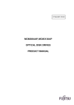
Figure 1. Formatted capacity
Notes:
1
Number of cylinders: For drives with capacities greater an 8.45 GB the IDENTIFY DEVICE information
word 01 limits the number of cylinders to 16,383 per the ATA specification.
2
Logical layout: Logical layout is an imaginary drive parameter (that is, the number of heads) which is
used to access the drive from the system interface. The Logical layout to Physical layout (that is, the
actual Head and Sectors) translation is done automatically in the drive. The default setting can be
obtained by issuing an IDENTIFY DEVICE command
Deskstar 180GXP hard disk drive specifications
9
4.2 Data sheet
Description
Data transfer rate (Mbps)
[Data transfer rate (Mbps) - optimized 40 GB]
Interface transfer rate (MB/s)
Data buffer size1 (KB)
Data buffer size1 (KB) - Models IC35L090AVV207-1,
IC35L120AVV207-1, IC35L180AVV207-1
Rotational speed (RPM)
Number of buffer segments (read)
Number of buffer segments (write)
Recording density - max (Kbpi)
[Recording density - max (Kbpi) - optimized 40 GB]
Track density max (Ktpi)
[Track density max (Ktpi) - optimized 40GB)
Areal density - max (Gbits/in2)
Number of data bands
699
648
100
2,048
8,192
7,200
up to 21
up to 63
632
578
76
72
46.3
27
1
Upper 226.5 KB is used for firmware
Figure 2. Mechanical positioning performance
Deskstar 180GXP hard disk drive specifications
10
4.3 Drive organization
4.3.1 Drive format
Upon shipment from Hitachi Globals Storage Technologies manufacturing the drive satisfies the sector
continuity in the physical format by means of the defect flagging strategy described in Section 5.0 on
page 19 in order to provide the maximum performance to users.
4.3.2 Cylinder allocation
All models except optimized 40GB
Optimized 40GB model
Data
Zone
Physical Cylinders
Blk/Trk
Physical Cylinders
Blk/Trk
0
1
2
3
4
5
6
7
8
9
10
11
12
13
14
15
16
17
18
19
20
21
22
23
24
25
26
0-1151
1152-5632
5633-9224
9225-12708
12709-16480
16481-18512
18513-21897
21898-23814
23815-27236
27237-29206
29207-32323
32324-34809
34810-38627
38628-40977
40978-43213
43214-46330
46331-47268
47269-50076
50077-50933
50934-54001
54002-57061
57062-59297
59298-61137
61138-63890
63891-66189
66190-68724
68725-70552
1,092
1,071
1,050
1,050
1,008
997
980
966
945
924
910
892
861
840
840
798
787
770
756
735
700
672
651
630
588
560
536
0 - 1010
1011-3262
3263-6101
6102-8098
8099-10150
10151-12157
12158-14453
14454-16913
16914-19093
19094-21116
21117-23091
23092-25371
25372-27587
27588-29280
29281-30884
30885-32135
32136-33866
33867-35554
35555-37014
37015-38443
38444-40044
40045-41606
41607-42683
42684-43740
43741-45380
45381-47025
47026-48622
1,008
997
980
966
945
945
924
910
892
861
861
840
840
798
798
787
756
756
735
735
700
700
672
672
651
630
630
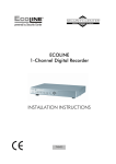
Figure 3. Cylinder allocation
Physical cylinder is calculated from the starting data track of 0. It is not relevant to logical CHS. Depending on the capacity some of the inner zone cylinders are not allocated.
Data cylinder
This cylinder contains the user data which can be sent and retrieved via read/write commands and a
spare area for reassigned data.
Spare cylinder
The spare cylinder is used by Hitachi Globobal Storage Technologies manufacturing and includes data
sent from a defect location.
Deskstar 180GXP hard disk drive specifications
11
4.4 Performance characteristics
Drive performance is characterized by the following parameters:
y Command overhead
y Mechanical positioning
- Seek time
- Latency
y Data transfer speed
y Buffering operation (Look ahead/Write cache)
All the above parameters contribute to drive performance. There are other parameters that contribute to
the performance of the actual system. This specification defines the characteristics of the drive, not the
characteristics of the system throughput which depends on the system and the application.
4.4.1 Command overhead
Command overhead is defined as the time required
y from the time the command is written into the command register by a host
y to the assertion of DRQ for the first data byte of a READ command when the requested data is not
in the buffer
y excluding Physical seek time and Latency
The table below gives average command overhead.
Time (Typical)
(ms)
Command type (Drive is in quiescent state)
Read (Cache not hit) (from Command Write to Seek Start)
Read (Cache hit) (from Command Write to DRQ)
Write (from Command Write to DRQ)
Seek (from Command Write to Seek Start)
0.3
0.1
0.015
0.3
Time (Typical) for
queued command
(ms)
0.3
0.1
0.05
not applicable
Figure 4. Command overhead
4.4.2 Mechanical positioning
4.4.2.1 Average seek time (without command overhead, including settling)
Command Type
Read (80 GB – 180 GB models)
Read (30 GB – 60 GB models)
Write (80 GB – 180 GB models
Write (30 GB – 60 GB models
Read (Quiet Seek mode)
Write (Quiet Seek mode)
Typical (ms)
8.2
8.5
9.2
9.5
19.5
20.5
Max (ms)
9.2
9.5
10.2
10.5
20.5
21.5
Figure 5. Mechanical positioning performance
Deskstar 180GXP hard disk drive specifications
12
The terms “Typical” and “Max” are used throughout this specification with the following meanings:
Typical. The average of the drive population tested at nominal environmental and voltage conditions.
Max. The maximum value measured on any one drive over the full range of the environmental
and voltage conditions. (See Section 6.4, “Environment” on page 45 and Section 6.5, “DC
Power Requirements” on page 47.
Seek time is measured from the start of the motion of the actuator to the start of a reliable read or write
operation. "Reliable read or write" implies that error correction/recovery is not used to correct arrival problems. The average seek time is measured as the weighted average of all possible seek combinations.
max.
Σ (max. + 1 – n) (Tnin + Tnout)
n=1
Weighted Average =
__________________________________________________
(max. + 1) (Tnin + Tnout)
where max
n
Tnin
Tnout
= maximum seek length
= seek length (1 to max)
= inward measured seek time for an n-track seek
= outward measured seek time for an n-track seek
4.4.2.2 Full stroke seek (without command overhead, including settling)
Function
Read (80 GB – 180 GB models)
Read (30 GB & 60 GB models)
Write (80 GB – 180 GB models)
Write (30 GB & 60 GB models)
Read (Quiet Seek mode)
Write (Quiet Seek mode)
Typical (ms)
14.7
15.1
15.7
16.1
32.5
33.5
Max (ms)
17.7
18.1
18.7
19.1
35.5
36.5
Figure 6. Full stroke seek time
Full stroke seek is measured as the average of 1000 full stroke seeks with a random head switch from
both directions (inward and outward).
4.4.2.3 Head switch time (Head skew)
72 kTPI
Head switch time - typical (ms)
1.4
Figure 7. Head switch time
Head switch time is defined as the amount of time required by the fixed disk to complete a seek of the
next sequential track after reading the last sector in the current track
The measuring method is given in 4.4.5 “Throughput” on page 16.
Deskstar 180GXP hard disk drive specifications
13
4.4.2.4 Cylinder switch time (Cylinder skew)
Cylinder switch time - typical (ms)
1.6
72 kTPI
Figure 8. Cylinder switch time
Cylinder switch time is defined as the amount of time required by the fixed disk to access the next
sequential block after reading the last sector in the current cylinder.
The measuring method is given in Section 4.4.5, “Throughput” on page 16.
4.4.2.5 Single track seek time (without command overhead, including settling)
Function
Read
Write
Read (Quiet Seek mode)
Write (Quiet Seek mode)
Typical (ms)
0.8
1.3
0.8
1.3
Max (ms)
1.5
2.0
1.5
2.0
Figure 9. Single Track Seek Time
Single track seek is measured as the average of one (1) single track seek from every track with a random
head switch in both directions (inward and outward).
4.4.2.6 Average latency
Time for a revolution
(ms)
8.3
Rotational speed
7200 RPM
Average latency
(ms)
4.17
Figure 10. Latency Time
4.4.3 Drive ready time
Power on to ready
60 GB models
120 GB models
180 GB models
Typical (sec)
6
8
10
Maximum (sec)
31
31
31
Figure 11. Drive ready time
Ready
Power on
The condition in which the drive is able to perform a media access command
(such as read, write) immediately.
This includes the time required for the internal self diagnostics.
Note: Max Power On to ready time is the maximum time period that Device 0 waits for Device 1 to assert
PDIAG–.
Deskstar 180GXP hard disk drive specifications
14
4.4.4 Data transfer speed
Data transfer speed
180 GB model
(Mbyte/s)
Disk-Buffer transfer (Zone 0)
Instantaneous - typical
Sustained - read typical
66
56.3
Disk-Buffer transfer (Zone 26)
Instantaneous - typical
Sustained - read typical
Buffer-Host (max)
34.5
29.4
100
Figure 12. Data transfer speed
y Instantaneous disk-buffer transfer rate (Mbyte/s) is derived by the following formula:
512 (Number of sectors on a track) (revolution per second)
Note: The number of sectors per track will vary because of the linear density recording.
y Sustained disk-buffer transfer rate (Mbyte/s) is defined by considering head/cylinder change time for
read operation. This gives a local average data transfer rate. It is derived by the following formula:
(Sustained Transfer Rate) = A / (B +C +D ) where
A = 512 (number of data sectors per cylinder)
B = (number of Surfaces per cylinder – 1) (head switch time)
C = cylinder change time
D = (number of surfaces) (time for one revolution)
y Instantaneous buffer-host transfer rate (Mbyte/s) defines the maximum data transfer rate on the
AT Bus. It also depends on the speed of the host.
The method of measurement is given in 4.4.5, "Throughput" on page 16.
Deskstar 180GXP hard disk drive specifications
15
4.4.5 Throughput
4.4.5.1 Simple sequential access
The following figure illustrates the case of the three-disk enclosure.
Operation
Sequential Read (Zone 0)
Sequential Read (Zone 26)
Typical (sec)
0.32
0.61
Max (sec)
0.34
0.64
Figure 13. Simple Sequential Access performance
The above table gives the time required to read a total of 8000h consecutive blocks (16,777,216 bytes)
accessed by 128 read commands. Typical and Max values are given by 105% and 110% of T
respectively throughout following performance description.
Note: It is assumed that a host system responds instantaneously and host data transfer is faster than
sustained data rate.
T = A + B + C + 16,777,216/D + 512/E
(READ)
where
T = Calculated time (sec)
A = Command process time (Command overhead) (sec)
B = Average seek time (sec)
C = Average latency (sec)
D = Sustained disk-buffer transfer rate (byte/sec)
E = Buffer-host transfer rate (byte/sec)
4.4.5.2 Random access
The following figure illustrates the case of the three-disk enclosure.
Operation
Random Read
Typical (sec)
56.3
Max (sec)
59.0
Figure 14. Random Access Performance
The above table gives the time required to execute a total of 1000h read commands which access a
single random LBA.
T = 4096 (A + B + C + 512/D + 512/E)
(READ)
where
T = Calculated time (sec)
A = Command process time (Command overhead) (sec)
B = Average seek time (sec)
C = Latency
D = Average sustained disk-buffer transfer rate (byte/s)
E = Buffer-host transfer rate (byte/s)
4.4.6 Operating modes
4.4.6.1 Operating mode descriptions
Deskstar 180GXP hard disk drive specifications
16
Operating mode
Description
Start up time period from spindle stop or power down
Seek operation mode
Write operation mode
Read operation mode
Spindle rotation at 7200 RPM with heads unloaded
Spin-up
Seek
Write
Read
Unload Idle
Idle
Spindle motor and servo system are working normally. Commands can be received and processed immediately
Actuator is unloaded and spindle motor is stopped. Commands can be
received immediately
Actuator is unloaded and spindle motor is stopped. Only soft reset or hard
reset can change the mode to standby
Standby
Sleep
Note: Upon power down or spindle stop a head locking mechanism will secure the heads in the OD parking position.
4.4.6.2 Mode transition times
Mode transition times are shown below.
From
To
RPM
Transition time
(typical )
(sec)
Transition time
(max)
(sec)
0 -> 7200 (3 disks)
9
31
7200 -> 0
Immediate
Immediate
Standby
Idle
Idle
Standby
Standby
Sleep
0
Immediate
Immediate
Sleep
Standby
0
Immediate
Immediate
Unload idle
Idle
7,200
0.7
Idle
Unload Idle
7,200
0.7
Note: The command is processed immediately but there will be an actual spin down time reflecting the
seconds passed until the spindle motor stops.
Figure 15. Mode transition times
Deskstar 180GXP hard disk drive specifications
17
This page intentionally left blank.
5.0 Defect flagging strategy
Media defects are remapped to the next available sector during the Format Process in manufacturing.
The mapping from LBA to the physical locations is calculated by an internally maintained table.
Shipped format
y Data areas are optimally used.
y No extra sector is wasted as a spare throughout user data areas.
y All pushes generated by defects are absorbed by the spare tracks of the inner zone.
N
N +1
d e fe c t
s k ip
N +2
d e fe c t
N +3
s k ip
Figure 16. PList physical format
Defects are skipped without any constraint, such as track or cylinder boundary. The calculation from LBA
to physical is done automatically by internal table.
Deskstar 180GXP hard disk drive specifications
19
This page intentionally left blank.
6.0 Specification
6.1 Electrical interface
6.1.1 Connector location
Refer to the following illustration to see the location of the connectors.
Figure 17. Connector location (2- and 3-disk model shown)
6.1.1.1 DC power connector
The DC power connector is designed to mate with AMP part number 1-480424-0 using AMP pins
part number 350078-4 (strip), part number 61173-4 (loose piece), or their equivalents. Pin assignments
are shown in the figure below.
4
3
2
1
Pin
1
2
3
4
Voltage
+12 V
GND
GND
+5V
Figure 18. Power connector pin assignments
6.1.1.2 AT signal connector
The AT signal connector is a 40-pin connector.
Deskstar 180GXP hard disk drive specifications
21
6.1.2 Signal definition
The pin assignments of interface signals are listed in the figure below:
PIN
SIGNAL
I/O
Type
PIN
SIGNAL
01
03
05
07
09
11
13
15
17
19
21
23
25
27
29
31
33
35
37
39
RESETDD7
DD6
DD5
DD4
DD3
DD2
DD1
DD0
GND
DMARQ
DIOW-(*)
DIOR-(*)
IORDY(*)
DMACKINTRQ
DA1
DA0
CSODASP-
I
I/O
I/O
I/O
I/O
I/O
I/O
I/O
I/O
TTL
3-state
3-state
3-state
3-state
3-state
3-state
3-state
3-state
O
I
I
O
I
O
I
I
I
I/O
3-state
TTL
TTL
3-state
TTL
3-state
TTL
TTL
TTL
OC
02
04
06
08
10
12
14
16
18
(20)
22
24
26
28
30
32
34
36
38
40
GND
DD8
DD9
DD10
DD11
DD12
DD13
DD14
DD15
key
GND
GND
GND
CSEL
GND
PDIAGDA2
CS1GND
I/O
Type
I/O
I/O
I/O
I/O
I/O
I/O
I/O
I/O
3-state
3-state
3-state
3-state
3-state
3-state
3-state
3-state
I
TTL
I/O
I
I
OC
TTL
TTL
Figure 19. Table of signals
Notes:
1. "O" designates an output from the drive.
2. "I" designates an input to the drive.
3. "I/O" designates an input/output common.
4. "OC" designates open-collector or open-drain output.
5. The signal lines marked with (*) are redefined during the Ultra DMA protocol to provide special
functions. These lines change from the conventional to special definitions at the moment the Host
decides to allow a DMA burst if the Ultra DMA transfer mode was previously chosen via
SetFeatures. The drive becomes aware of this change upon assertion of the DMACK- line. These
lines revert back to their original definitions upon the deassertion of DMACK- at the termination of
the DMA burst.
Write Operation
Read Operation
Special Definition
(for Ultra DMA)
DDMARDYHSTROBE
STOP
HDMARDYDSTROBE
STOP
Conventional Definition
IORDY
DIORDIOWDIORIORDY
DIOW-
Figure 20. Signal special definitions for Ultra DMA
DD0-DD15
16-bit bi-directional data bus between the host and the drive. The lower 8 lines, DD00-07,
are used for Register and ECC access. All 16 lines, DD00-15, are used for data transfer.
These are 3-State lines with 24 mA current sink capability.
Deskstar 180GXP hard disk drive specifications
22
DA0-DA2
Address used to select the individual register in the drive.
CS0-
Chip select signal generated from the Host address bus. When active, one of the
Command Block Registers (Data, Error {Features when written}, Sector Count, Sector
Number, Cylinder Low, Cylinder High, Drive/Head and Status {Command when written}
register) can be selected. (See Figure 43 on page 38.)
CS1-
Chip select signal generated from the Host address bus. When active one of the Control
Block Registers (Alternate Status {Device Control when written} and Drive Address
register) can be selected. (See Figure 43 on page 38.)
RESET-
This line is used to reset the drive. It shall be kept in Low logic state during power up and
in High thereafter.
DIOW-
Its rising edge holds data from the host data bus to a register or data register of the drive.
DIOR-
When low, this signal enables data from a register or data register of the drive onto data
bus. The data on the bus shall be latched on the rising edge of DIOR-.
INTRQ
Interrupt is enabled only when the drive is selected and the host activates the nIEN bit in
the Device Control Reg. Otherwise, this signal is in high impedance state regardless of
the state of the IRQ bit. The interrupt is set when the IRQ bit is set by the drive CPU. IRQ
is reset to zero by a host read of the status register or a write to the Command Reg. This
signal is a 3-State line with 24 mA sink capability.
DASP-
This is a time-multiplexed signal which indicates that a drive is active, or that device 1 is
present. This signal is driven by Open-Drain driver and internally pulled up to 5 volts
through a 10kΩ resistor.
During Power-On initialization or after RESET- is negated, DASP- shall be asserted by
Device 1 within 400 ms to indicate that device 1 is present. Device 0 shall allow up to
450 ms for device 1 to assert DASP-. If device 1 is not present, device 0 may assert
DASP- to drive a LED indicator.
DASP- shall be negated following acceptance of the first valid command by device 1. At
anytime after negation of DASP-, either drive may assert DASP- to indicate that a drive is
active.
PDIAG-
PDIAG- shall be asserted by device 1 to indicate to device 0 that it has completed diagnostics. This line is pulled-up to 5 volts in the drive through a 10kΩ resistor.
Following a Power On Reset, software reset, or RESET-, drive 1 shall negate PDIAGwithin 1 ms (to indicate to device 0 that it is busy). Drive 1 shall then assert PDIAGwithin 30 seconds to indicate that it is no longer busy and is able to provide status.
Following the receipt of a valid Execute Drive Diagnostics command, device 1 shall
negate PDIAG- within 1 ms to indicate to device 0 that it is busy and has not yet passed
its drive diagnostics. If device 1 is present, device 0 shall wait up to 6 seconds from the
receipt of a valid Execute Drive Diagnostics command for drive 1 to assert PDIAG-.
Device 1 should clear BSY before asserting PDIAG-, as PDIAG- is used to indicate that
device 1 has passed its diagnostics and is ready to post status.
If device 1 did not assert DASP- during reset initialization, device 0 shall post its own
status immediately after it completes diagnostics and clear the device 1 Status register to
00h. Device 0 may be unable to accept commands until it has finished its reset procedure
and is ready (DRDY=1).
Device 1 shall release PDIAG-/CBLID- no later than after the first command following a
power on or hardware reset sequence so that the host may sample PDIAG-/CBLID- in
order to detect the presence or absence of an 80-conductor cable assembly.
CSEL (Cable Select) (Optional)
Deskstar 180GXP hard disk drive specifications
23
The drive is configured as either Device 0 or 1 depending upon the value of CSEL.
y If CSEL is grounded, the device address is 0
y If CSEL is open, the device address is 1
KEY
Pin position 20 has no connection pin. It is recommended to close the respective position
of the cable connector in order to avoid incorrect insertion by mistake.
IORDY
This signal is negated to extend the host transfer cycle when a drive is not ready to
respond to a data transfer request and may be negated when the host transfer cycle is
less than 240 ns for PIO data transfer. This signal is an open-drain output with 24 mA
sink capability and an external resistor is needed to pull this line to 5 volts.
DMACK-
This signal shall be used by the host in response to DMARQ to either acknowledge that
data has been accepted or that data is available.
This signal is internally pulled up to 5 V through a 15 KΩ resistor. The tolerance of the
resistor value is –50% to +100%.
DMARQ
This signal, used for DMA data transfers between host and drive, shall be asserted by
the drive when it is ready to transfer data to or from the host. The direction of data transfer is controlled by DIOR- and DIOW-. This signal is used on a handshake manner with
DMACK-. This signal is a 3-state line with 24mA sink capability and internally pulled
down to GND through 10 KΩ resistor.
HDMARDY- (Ultra DMA)
This signal is used only for Ultra DMA data transfers between the host and the device.
HDMARDY- is a flow control signal for Ultra DMA data in bursts. This signal is held
asserted by the host to indicate to the device that the host is ready to receive Ultra DMA
data in transfers. The host may negate HDMARDY- to pause an Ultra DMA data in
transfer.
HSTROBE (Ultra DMA)
This signal is used only for Ultra DMA data transfers between the host and the device.
HSTROBE is the data out strobe signal from the host for an Ultra DMA data out transfer.
Both the rising and falling edge of HSTROBE latch the data from DD(15:0) into the
device. The host may stop toggling HSTROBE to pause an Ultra DMA data out transfer.
STOP (Ultra DMA)
This signal is used only for Ultra DMA data transfers between the host and the device.
STOP shall be asserted by the host prior to initiation of an Ultra DMA burst. STOP shall
be negated by the host before data is transferred in an Ultra DMA burst. Assertion of
STOP by the host during or after data transfer in an Ultra DMA mode signals the termination of the burst.
DDMARDY- (Ultra DMA)
This signal is used only for Ultra DMA data transfers between the host and the device.
DDMARDY- is a flow control signal for Ultra DMA data out bursts. This signal is held asserted by the device to indicate to the host that the device is ready to receive Ultra DMA
data out transfers. The device may negate DDMARDY- to pause an Ultra DMA data out
transfer.
DSTROBE (Ultra DMA)
This signal is used only for Ultra DMA data transfers between the host and the device.
DSTROBE is the data in strobe signal from the device for an Ultra DMA data in transfer.
Both the rising and falling edge of DSTROBE latch the data from DD(15:0) into the host.
The device may stop toggling DSTROBE to pause an Ultra DMA data in transfer.
Device Termination
Deskstar 180GXP hard disk drive specifications
24
The termination resistors on the device side are implemented on the drive side as
follows:
y33 Ω for DD0 thru DD15, DMARQ, INTRQ
y82 Ω for CS0-, CS1-, DA0, DA1, DA2, DIOR-, DIOW-, DMACKy22 Ω for IORDY
6.1.3 Interface logic signal levels
The interface logic signal has the following electrical specifications:
Inputs
Outputs
Input High Voltage
Input Low Voltage
2.0 V min.
0.8 V max.
Output High Voltage
Output Low Voltage
2.4 V min.
0.5 V max.
Deskstar 180GXP hard disk drive specifications
25
6.2 Signal timings
6.2.1 Reset timings
Drive reset timing.
RESETt10
BUSY
t14
Figure 21. System reset timing chart
PARAMETER DESCRIPTION
t10
t14
RESET low width
RESET high to not BUSY
Min (usec)
Max (sec)
25
–
31
Figure 22. System reset timing
Deskstar 180GXP hard disk drive specifications
26
6.2.2 PIO timings
The PIO cycle timings meet Mode 4 of the ATA/ATAPI-6 description.
CS(1:0)
DA(2:0)
t9
t1
t0
DIOR-,
DIOWt2
t2i
Write data
DD(15:0)
t3
t4
Read data
DD(15:0)
t5
tA
t6
tB
IORDY
(*) Up to ATA-2
(mode-0,1,2)
Figure 23. PIO cycle timings chart
PARAMETER DESCRIPTION
t0
t1
t2
t2i
t3
t4
t5
t6
t9
tA
tB
Cycle time
Address valid to DIOR-/DIOW– setup
DIOR–/DIOW– pulse width
DIOR–/DIOW– recovery time
DIOW– data setup
DIOW– data hold
DIOR– data setup
DIOR– data hold
DIOR–/DIOW– to address valid hold
IORDY set up time
IORDY pulse width
MIN (ns)
MAX (ns)
120
25
70
25
20
10
20
5
10
–
–
–
–
–
–
–
–
–
–
35
1250
Figure 24. PIO cycle timings
6.2.2.1 Write DRQ interval time
For write sectors and write multiple operations 3.8 µs is inserted from the end of negation of the DRQ bit
until setting of the next DRQ bit.
Deskstar 180GXP hard disk drive specifications
27
6.2.2.2 Read DRQ interval time
For read sectors and read multiple operations the interval from the end of negation of the DRQ bit until
setting of the next DRQ bit is as follows:
y In the event that a host reads the status register only before the sector or block transfer DRQ
interval, the DRQ interval 4.2 µs
y In the event that a host reads the status register after or both before and after the sector or block
transfer, the DRQ interval is 11.5 µs
Deskstar 180GXP hard disk drive specifications
28
6.2.3 Multiword DMA timings
The Multiword DMA timing meets Mode 2 of the ATA/ATAPI-6 description.
CS0-/CS1-
tM
tN
tLR/tLW
DMARQ
tJ
t0
DMACKtI
tD
tKR/tKW
DIOR-/DIOWtE
tG
tZ
tF
READ DATA
tG
tH
WRITE DATA
Figure 25. Multiword DMA cycle timing chart
PARAMETER DESCRIPTION
t0
tD
tE
tF
tG
tH
tI
tJ
tKR/tKW
tLR/tLW
tM
tN
tZ
Cycle time
DIOR–/DIOW– asserted pulse width
DIOR– data access
DIOR– data hold
DIOR–/DIOW– data setup
DIOW– data hold
DMACK– to –DIOR–/DIOW– setup
DIOR–/DIOW– to DMACK– hold
DIOR–/DIOW– negated pulse width
DIOR–/DIOW– to DMARQ– delay
CS (1:0) valid to DIOR–/DIOW–
CS (1:0) hold
DMACK– to read data released
MIN (ns)
MAX (ns)
120
70
–
5
20
10
0
5
25
–
25
10
–
–
–
50
–
–
–
–
–
–
35
–
–
25
Figure 26. Multiword DMA cycle timings
Deskstar 180GXP hard disk drive specifications
29
6.2.4 Ultra DMA timings
The Ultra DMA timing meets Mode 0,1,2,3 4, and 5 of the Ultra DMA Protocol.
6.2.4.1 Initiating Read DMA
DMARQ
tUI
DMACKtACK
tENV
tACK
tENV
STOP
t2CYC
HDMARDY-
tCYC
tDZFS
DSTROBE
xxxxxxxxxxxxxxxxxxxxxxxxx
tDH
tDS
tZAD
tAZ
DD(15:00)
tCYC
tFS
tZIORDY
tDH
tDS
xxx RD Data xxx RD Data xxx
RD Data
Device drives DD
Host drives DD
Figure 27. Ultra DMA cycle timing chart (Initiating Read)
PARAMETER DESCRIPTION
(all values in ns)
tUI
tACK
tENV
tZIORDY
tFS
tCYC
t2CYC
tAZ
tZAD
tDS
tDH
tDZFS
Unlimited interlock time
Setup time before –DMACK
Envelope time
Minimum time before driving
IORDY
First DSTROBE time
Cycle time
Two cycle time
Maximum time allowed for
output drivers to release
Maximum time allowed for
output drivers to assert
Data setup time (at host)
Data hold time (at host)
Time from data output released-to-driving until the first
transition of critical timing
MODE0
MODE1
MODE2
MODE3
MODE4
MODE5
MIN MAX MIN MAX MIN MAX MIN MAX MIN MAX MIN MAX
0
20
20
–
–
70
0
20
20
–
–
70
0
20
20
0
–
70
0
20
20
–
–
55
20
0
–
0
–
0
–
0
0
230
0
200
0
170
112
–
73
–
54
–
230
–
153
–
115
–
0
20
–
–
55
0
20
20
–
–
50
–
0
–
0
–
0
39
86
130
–
–
0
25
57
120
–
–
0
17
38
90
–
–
–
10
–
10
–
10
–
10
–
10
–
10
0
–
0
–
0
–
0
–
0
–
0
–
15
5
–
–
10
5
–
–
7
5
–
–
7
5
–
–
5
5
–
–
4
4.6
–
–
70
-
48
-
31
-
20
-
6.7
-
25
-
Figure 28. Ultra DMA cycle timings (Initiating Read)
Deskstar 180GXP hard disk drive specifications
30
6.2.4.2 Host Pausing Read DMA
DMARQ
DMACKSTOP
tSR
HDMARDYtRFS
DSTROBE
Figure 29. Ultra DMA cycle timing chart (Host pausing Read)
PARAMETER DESCRIPTION
(all values in ns)
tSR
tRFS
DSTROBE to HDMARDY– time
HDMARDY– to final DSTROBE time
MODE0
MODE1
MODE2
MODE3
MODE4
MODE5
MIN MAX MIN MAX MIN MAX MIN MAX MIN MAX MIN MAX
–
50
–
30
–
20
–
–
–
–
–
–
–
75
–
70
–
60
–
60
–
60
–
50
Note: When a host does not satisfy tSR timing, it should be ready to receive two more data words after
HDMARDY– is negated.
Figure 30. Ultra DMA cycle timings (Host pausing Read)
Deskstar 180GXP hard disk drive specifications
31
6.2.4.3 Host Terminating Read DMA
DMARQ
tLI
tMLI
DMACKtACK
tRP
STOP
tACK
HDMARDYtLI
tRFS
tIORDYZ
DSTROBE
DD(15:00)
tCS
tAZ
xxx RD Data xxxxxxxxxxxxxxxxxx
xxx
tCH
CRC
xxxxxxxxxx
tZAH
Device drives DD
Host drives DD
Figure 31. Ultra DMA cycle timing chart (Host terminating Read)
MODE0
MODE1
MODE2
MODE3
MODE4
MODE5
PARAMETER DESCRIPTION
(all values in ns)
MIN MAX MIN MAX MIN MAX MIN MAX MIN MAX MIN MAX
HDMARDY– to final
–
DSTROBE time
tRP
Ready to pause time
160
tLI
Limited interlock time
0
Maximum time allowed for
tAZ
–
output drivers to release
Minimum delay time required
tZAH
20
for output
Interlocking time with
tMLI
20
minimum
CRC word setup time (at
tCS
15
device side)
CRC word hold time (at device
tCH
5
side)
tACK
Hold time for DMACK –
20
Maximum time before
–
tIORDYZ
releasing IORDY
tRFS
75
–
70
–
60
–
60
–
60
–
50
–
150
125
0
–
150
100
0
–
150
100
0
–
100
100
0
–
100
85
0
–
75
10
–
10
–
10
–
10
–
10
–
10
–
20
–
20
–
20
–
20
–
20
–
–
20
–
20
–
20
–
20
–
20
–
–
10
–
7
–
7
–
5
–
5
–
–
5
–
5
–
5
–
5
–
5
–
–
20
–
20
–
20
–
20
–
20
–
20
–
20
–
20
–
20
–
20
–
20
Figure 32. Ultra DMA cycle timings (Host terminating Read)
Deskstar 180GXP hard disk drive specifications
32
6.2.4.4 Device Terminating Read DMA
DMARQ
tSS
tMLI
DMACKtLI
tACK
tLI
tACK
STOP
HDMARDYtLI
tIORDYZ
DSTROBE
DD(15:00)
tCS
tAZ
xxxxx
xxxxxxxxxxxxxxxxxx
tCH
xxxxxxxxxx
CRC
tZAH
Host drives DD
Device drives DD
Figure 33. Ultra DMA cycle timing chart (Device terminating Read)
PARAMETER DESCRIPTION
(all values in ns)
tSS
tLI
tAZ
tZAH
tMLI
tCS
tCH
tACK
tIORDYZ
Time from DSTROBE edge to
negation of DMARQ
Limited interlock time
Maximum time allowed for
output drivers to release
Minimum delay time required
for output
Interlock time with minimum
CRC word setup time (at device
side)
CRC word hold time (at device
side)
Hold time after DMACK–
Maximum time before releasing
IORDY
MODE0
MODE1
MODE2
MODE3
MODE4
MODE5
MIN MAX MIN MAX MIN MAX MIN MAX MIN MAX MIN MAX
50
–
50
–
50
–
50
–
50
–
50
–
0
150
0
150
0
150
0
100
0
100
0
75
–
10
–
10
–
10
–
10
–
10
–
10
20
–
20
–
20
–
20
–
20
–
20
–
20
–
20
–
20
–
20
–
20
–
20
–
15
–
10
–
7
–
7
–
5
–
5
–
5
–
5
–
5
–
5
–
5
–
5
–
20
–
20
–
20
–
20
–
20
–
20
–
–
20
–
20
–
20
–
20
–
20
–
20
Figure 34. Ultra DMA cycle timings (Device Terminating Read)
Deskstar 180GXP hard disk drive specifications
33
6.2.4.5 Initiating Write DMA
DMARQ
tUI
DMACKtACK
tENV
STOP
tZIORDY
tLI
t2CYC
DDMARDYtACK
tCYC
tUI
HSTROBE
tDH
tDS
DD(15:0)
tCYC
tDS tDH
xxxxxxxxxxxxxxxxxxxxxxxxxxxxxxx WT Data xxx WT Data xxx WT Data
Host drives DD
Figure 35. Ultra DMA cycle timing chart (Initiating Write)
PARAMETER DESCRIPTION
(all values in ns)
tUI
tACK
tENV
tZIORDY
tLI
tCYC
t2CYC
tDS
tDH
MODE0
MODE1
MODE2
MODE3
MODE4
MODE5
MIN MAX MIN MAX MIN MAX MIN MAX MIN MAX MIN MAX
Unlimited interlock time
0
–
0
–
0
Setup time before DMACK–
20
–
20
–
20
Envelope time
20
70
20
70
20
Minimum time before driving
0
–
0
–
0
IORDY
Limited interlock time
0
150
0
150
0
Cycle time
112
–
73
–
54
Two Cycle time
230
–
154
–
115
Data setup time (at device side) 15
–
10
–
7
Data hold time (at device side)
5
–
5
–
5
–
–
70
0
20
20
–
–
55
0
20
20
–
–
55
0
20
20
–
–
50
–
0
–
0
–
0
–
150
–
–
–
–
0
39
86
7
5
100
–
–
–
–
0
25
57
5
5
Figure 36. Ultra DMA cycle timings (Initiating Write)
Deskstar 180GXP hard disk drive specifications
34
100
0
– 16.8
–
38
–
4
–
4.6
75
–
–
–
–
6.2.4.6 Device Pausing Write DMA
DMARQ
DMACKSTOP
tSR
DDMARDYtRFS
HSTROBE
Figure 37. Ultra DMA cycle timing chart (Device Pausing Write)
PARAMETER DESCRIPTION
(all values in ns)
tSR
tRFS
HSTROBE to DDMARDY–
response time
DDMARDY– to final HSTROBE
time
MODE0
MODE1
MODE2
MODE3
MODE4
MODE5
MIN MAX MIN MAX MIN MAX MIN MAX MIN MAX MIN MAX
–
50
–
30
–
20
–
–
–
–
–
–
75
–
70
–
60
–
60
–
60
–
50
Note: When a device does not satisfy the tSR timing, it shall be ready to receive two more strobes after
DDMARDY– is negated.
Figure 38. Ultra DMA cycle timings (Device Pausing Write)
Deskstar 180GXP hard disk drive specifications
35
6.2.4.7 Device Terminating Write DMA
DMARQ
tLI
tRP
tMLI
DMACKtACK
STOP
tIORDYZ
DDMARDYtACK
tLI
tRFS
HSTROBE
tCS
DD(15:00)
xxx WT Data xxxxxxxxxxxxxxxxxxxxxxxxxx
tCH
xxxxxxxxxx
CRC
Host drives DD
Figure 39. Ultra DMA cycle timing chart (Device Terminating Write)
PARAMETER DESCRIPTION
(all values in ns)
tRFS
tRP
tLI
tMLI
tCS
tCH
tACK
tIORDYZ
DDMARDY to final HSTROBE
time
Ready to pause time
Limited interlock time
Interlock time with minimum
CRC word setup time (at device
side)
CRC word hold time (at device
side)
Hold time for –DMACK
Maximum time before releasing
IORDY
MODE0
MODE1
MODE2
MODE3
MODE4
MODE5
MIN MAX MIN MAX MIN MAX MIN MAX MIN MAX MIN MAX
–
75
–
70
–
160
–
125
–
100
0
150
0
150
0
20
–
20
–
20
60
–
150
–
–
60
–
60
–
50
100
–
100
–
0
100
0
100
20
–
20
–
85
0
20
–
75
–
15
–
10
–
7
–
7
–
5
–
5
–
5
–
5
–
5
–
5
–
5
–
5
–
20
–
20
–
20
–
20
–
20
–
20
–
–
20
–
20
–
20
–
20
–
20
–
20
Figure 40. Ultra DMA cycle timings (Device terminating Write)
Deskstar 180GXP hard disk drive specifications
36
6.2.4.8 Host Terminating Write DMA
DMARQ
tLI
tMLI
DMACKtACK
tSS
STOP
tLI
tIORDYZ
DDMARDYtLI
tACK
HSTROBE
tCS
DD(15:00)
xxxxxxxxxxxxxxxxxxxxxxxxxxxxxxxxxxxxx
tCH
CRC
xxxxxxxxxx
Host drives DD
Figure 41. Ultra DMA cycle timing chart (Host Terminating Write)
PARAMETER DESCRIPTION
(all values in ns)
tSS
tLI
tMLI
tCS
tCH
tACK
tIORDYZ
Time from HSTROBE to edge
assertion of STOP
Limited interlock time
Interlock time with minimum
CRC word setup time (at device
side)
CRC word hold time (at device
side)
Hold time for DMACK–
Maximum time before releasing
IORDY
MODE0
MODE1
MODE2
MODE3
MODE4
MODE5
MIN MAX MIN MAX MIN MAX MIN MAX MIN MAX MIN MAX
50
–
50
–
50
–
50
–
50
–
50
–
0
20
150
–
0
20
150
–
0
20
150
–
0
20
100
–
0
20
100
–
0
20
75
–
15
–
10
–
7
–
7
–
5
–
5
–
5
–
5
–
5
–
5
–
5
–
5
–
20
–
20
–
20
–
20
–
20
–
20
–
–
20
–
20
–
20
–
20
–
20
–
20
Figure 42. Ultra DMA cycle timings (Host Terminating Write)
Deskstar 180GXP hard disk drive specifications
37
6.2.5 Addressing of registers
The host addresses the drive through a set of registers called the Task File. These registers are mapped
into the I/ O space of the host. Two chip select lines (CS0– and CS1–) and three address lines (DA0-02)
are used to select one of these registers, while a DIOR– or DIOW– is provided at the specified time.
The CS0– is used to address Command Block registers. while the CS1– is used to address Control Block
registers.
The following table shows the I/ O address map.
CS0– CS1–
DA2
DA1
DA0
DIOR– = 0 (Read)
DIOW– = 0 (Write)
Command Block Registers
0
0
0
0
0
0
0
0
1
1
1
1
1
1
1
1
0
0
0
0
1
1
1
1
0
0
1
1
0
0
1
1
0
1
0
1
0
1
0
1
Data Reg.
Error Reg.
Sector count Reg.
Sector number Reg.
Cylinder low Reg.
Cylinder high Reg.
Drive/Head Reg.
Status Reg.
Data Reg.
Features Reg.
Sector count Reg.
Sector number Reg.
Cylinder low Reg.
Cylinder high Reg.
Drive/Head Reg.
Command Reg.
Control Block Registers
1
0
1
1
0
Alt. Status Reg.
Device control Reg.
Figure 43. I/O address map
Note: "Addr" field is shown as an example.
During DMA operation (from writing to the command register until an interrupt) not all registers are accessible. For example, the host is not supposed to read status register contents before interrupt (the value is
invalid).
6.2.6 Cabling
The maximum cable length from the host system to the drive plus circuit pattern length in the host system
shall not exceed 18 inches.
For higher data transfer application (>8.3 MB/s) a modification in the system design is recommended to
reduce cable noise and cross-talk, such as a shorter cable, bus termination, or a shielded cable.
For systems operating with Ultra DMA mode 3, 4, and 5, 80-conductor ATA cable assembly (SFF-8049)
shall be used.
Deskstar 180GXP hard disk drive specifications
38
6.3 Jumper settings
6.3.1 Jumper pin location
Jumper pins
Figure 44. Jumper pin location (2- and 3-disk model shown)
6.3.2 Jumper pin identification
Pin I
Pin A
DERA001.prz
Pin B
Figure 45. Jumper pin identification (2- and 3-disk model shown)
Deskstar 180GXP hard disk drive specifications
39
6.3.3 Jumper pin assignment
There are four jumper settings as shown in the following sections:
y
y
y
y
16 logical head default (normal use)
15 logical head default
2 GB/32 GB clip
Power up in standby
Within each of these four jumper settings the pin assignment selects Device 0, Device 1, Cable Selection,
or Device 1 Slave Present as shown in the following figures.
The Device 0 setting automatically recognizes device 1 if it is present.
The Device 1 Slave Present setting is for a slave device that does not comply with the ATA specification.
Note: In conventional terminology "Device 0" designates a Master and "Device 1" designates a Slave.
RSV
GND
GND
GND
RSV
I
G
E
C
A
H
F
D
B
DS
CS/SP
GND
RS V
Figure 46. Jumper pin assignment
Deskstar 180GXP hard disk drive specifications
40
6.3.4 Jumper positions
6.3.4.1 16 logical head default (normal use)
The figure below shows the jumper positions used to select Device 0, Device 1, Cable Selection, or
Device 1 (Slave) Present.
I
G
H
E
F
C
D
A
B
DEVICE 0
(Master)
I
G
H
E
F
C
D
A
B
DEVICE 1
(Slave)
I
G
H
E
F
C
D
A
B
CABLE SEL
I
G
H
E
F
C
D
A
B
DEVICE 1
I
G
H
E
F
C
D
A
B
Shipping Default Condition
(DEVICE 0)
(Slave) Present
Figure 47. Jumper positions for normal use
Notes:
1. To enable the CSEL mode (Cable Selection mode) the jumper block must be installed at E-F. In the
CSEL mode the drive address is determined by AT interface signal #28 CSEL as follows:
y When CSEL is grounded or at a low level, the drive address is 0 (Device 0).
y When CSEL is open or at a high level, the drive address is 1 (Device 1).
2. In CSEL mode, installing or removing the jumper blocks at A-B or C-D position does not affect any
selection of Device or Cable Selection mode.
3. The shipping default position is the Device 0 position.
Deskstar 180GXP hard disk drive specifications
41
6.3.4.2 15 logical head default
The figure below shows the jumper positions used to select Device 0, Device 1, Cable Selection, or
Device 1 (Slave) Present setting 15 logical heads instead of default 16 logical head models.
I
G
H
E
F
C
D
A
B
DEVICE 0 (Master)
I
G
H
E
F
C
D
A
B
DEVICE 1 (Slave)
I
G
H
E
F
C
D
A
B
CABLE SEL
I
G
H
E
F
C
D
A
B
DEVICE 1 (Slave) Present
Figure 48. Jumper positions for 15 logical head default
Notes:
1. To enable the CSEL mode (Cable Selection mode) the jumper block must be installed at E-F. In the
CSEL mode, the drive address is determined by AT interface signal #28 CSEL as follows:
y When CSEL is grounded or at a low level, the drive address is 0 (Device 0).
y When CSEL is open or at a high level, the drive address is 1 (Device 1).
2. In CSEL mode, installing or removing the jumper blocks at A-C or B-D position does not affect any
selection of Device or Cable Selection mode.
Deskstar 180GXP hard disk drive specifications
42
6.3.4.3 Capacity clip to 2GB/32GB
The figure below shows the jumper positions used to select Device 0, Device 1, Cable Selection, or
Device 1 (Slave) Present while setting the drive capacity down either to 2 GB or 32 GB for the purpose of
compatibility.
I
G
H
E
F
C
D
A
B
DEVICE 0 (Master)
I
G
H
E
F
C
D
A
B
DEVICE 1 (Slave)
I
G
H
E
F
C
D
A
B
CABLE SEL
I
G
H
E
F
C
D
A
B
DEVICE 1 (Slave) Present
Figure 49. Jumper positions for capacity clip to 2GB/32GB
Notes:
For the 30-GB model (factory default capacities less than 32GB):
The jumper setting acts as a 2GB clip which clips the CHS to 4096/16/63. The LBA is unchanged from
the factory default setting (dependent on the particular model).
For all other models (factory default capacities greater than 32GB):
The jumper setting acts as a 32GB clip which clips the LBA to 66055248. The CHS is unchanged from
the factory default of 16383/16/63.
Deskstar 180GXP hard disk drive specifications
43
6.3.4.4 Power Up In Standby
The figure below shows the jumper positions used to select Device 0, Device 1, Cable Selection, or
Device 1 (Slave) Present to enable Power Up In Standby.
I
G
H
E
F
C
D
A
B
DEVICE 0 (Master)
I
G
H
E
F
C
D
A
B
DEVICE 1 (Slave)
I
G
H
E
F
C
D
A
B
CABLE SEL
I
G
H
E
F
C
D
A
B
DEVICE 1 (Slave) Present
Figure 50. Jumper settings for Disabling Auto Spin
Notes:
1. These jumper settings are used for limiting power supply current when multiple drives are used.
2. Command to spin up is SET FEATURES (subcommand 07h). Refer to 12.28 Set Features.
3. To enable the CSEL mode (Cable Selection mode) the jumper block must be installed at E-F. In
CSEL mode, the drive address is determined by AT interface signal #28 as follows:
y When CSEL is grounded or at a low level, the drive address is 0 (Device 0).
y When CSEL is open or at a high level, the drive address is 1 (Device 1).
Deskstar 180GXP hard disk drive specifications
44
6.4 Environment
6.4.1 Temperature and humidity
Operating conditions
Temperature
Relative humidity
Maximum wet bulb temperature
Maximum temperature gradient
Altitude
Non-Op conditions
Temperature
Relative humidity
Maximum wet bulb temperature
Altitude
5 to 55°C
8 to 90% non-condensing
29.4°C non-condensing
15°C/Hour
–300 to 3,048 m
-40 to 65°C
5 to 95% non-condensing
35°C non-condensing
–300 to 12,000 m
Figure 51. Temperature and humidity
Notes:
1. The system is responsible for providing sufficient ventilation to maintain a surface temperature
below 60°C at the center of the top cover of the drive.
2. Noncondensing conditions should be maintained at any time.
3. Maximum storage period within shipping package is one year.
Deskstar 180GXP hard disk drive specifications
45
Environment Specification
100
36C/95%
90
31C/90%
Wet Bulb 35C
Relative Humidity (%)
80
Wet Bulb 29.4C
70
60
Nonoperating
50
Operating
40
30
65C/14%
20
55C/15%
10
0
-40
-20
0
20
40
60
Temperature (C)
Figure 52. Limits of temperature and humidity
Note: Storage temperature range is 0° to 65°.
6.4.2 Corrosion test
The drive shows no sign of corrosion inside and outside of the hard disk assembly and is functional after
being subjected to seven days at 50°C with 90% relative humidity.
Deskstar 180GXP hard disk drive specifications
46
6.5 DC power requirements
The following voltage specifications apply at the power connector of the drive. Damage to the drive
electronics may result if the power supply cable is connected or disconnected while power is being
applied to the drive (no hot plug/unplug is allowed). Connections to the drive should be made in a low
voltage, isolated secondary circuit (SELV). There is no special power on/off sequencing required.
6.5.1 Input voltage
Input voltage
During run and spin up
+5 Volts Supply
+12 Volts Supply
5V ± 5%
12V +10% –8%
Absolute max
spike voltage1
–0.3 to 7V
–0.3 to 15V
Figure 53. Input voltage
Note: To avoid damage to the drive electronics, power supply voltage spikes must not exceed specifications.
6.5.2 Power supply current (typical)
Power supply current of
180-GB model
(values in milliamps. RMS)
Idle average
Idle ripple (peak-to-peak)
Low RPM idle
Low RPM idle ripple
Unload idle average
Unload idle ripple
Seek average 1
Seek peak
Random R/W average
Random R/W peak
Silent R/W average
Silent R/W peak
Start up (max)
Standby average
Sleep average
2
+5 Volts [mA]
+12 Volts [mA]
Pop Mean
280
410
130
50
Std Dev
2
5
6
1
Pop Mean
470
610
180
350
Std Dev
18
24
8
20
130
50
330
590
490
1150
480
1150
830
140
100
2
2
4
6
6
17
6
17
21
3
9
350
410
690
1950
660
1950
530
990
1860
20
20
20
30
11
19
16
19
20
14
37
1
1
Figure 54. Power supply current of 180 GB models
Except for a peak of less than 100 µs duration
1
Random seeks at 40% duty cycle
2
Seek duty = 30%, W/R duty = 45%, Idle Duty = 25%
Deskstar 180GXP hard disk drive specifications
47
Total
[W]
7.0
2.9
4.9
10.0
10.3
8.7
0.9
0.7
Power supply current of
120-GB and 80-GB models
(values in milliamps. RMS)
Idle average
Idle ripple (peak-to-peak)
Low RPM Idle
Low RPM Idle Ripple
+5 Volts [mA]
Unload Idle average
Unload Idle Ripple
Seek average1
Seek peak
Random R/W average2
Random R/W peak
Silent R/W average
Silent R/W peak
Start up (max)
Standby average
Sleep average
+12 Volts [mA]
Pop Mean
280
410
140
60
Std Dev
1
8
5
3
Pop Mean
380
490
140
400
Std Dev
12
8
6
17
140
50
330
590
490
1160
490
1160
860
140
100
4
2
2
7
5
18
6
18
30
4
4
300
340
610
1790
580
1790
460
890
1750
20
20
5
5
11
11
9
11
9
13
21
1
1
Total
[W]
5.9
2.4
4.3
8.9
9.4
7.9
0.9
0.7
Figure 55. Power supply current of 80 GB and 120 GB models
Power supply current of 60-GB,
40-GB, and 30-GB models
(values in milliamps. RMS)
Idle average
Idle ripple (peak-to-peak)
Low RPM idle
Low RPM idle ripple
Unload idle average
Unload idle ripple
Seek average1
Seek peak
Random R/W average2
Random R/W peak
Silent R/W average
Silent R/W peak
Start up (max)
Standby average
Sleep average
+5 Volts [mA]
+12 Volts [mA]
Pop Mean
280
430
140
50
Std Dev
8
4
6
3
Pop Mean
300
410
140
380
Std Dev
5
7
3
19
140
40
330
600
490
1170
480
1170
840
140
100
6
4
9
9
7
17
6
17
40
9
7
270
310
520
1550
490
1550
380
810
1730
20
20
6
15
12
40
10
40
8
8
13
1
1
Figure 56. Power supply current of 60 GB, 40GB, and 30 GB models
Except for a peak of less than 100 µs duration
1
Random seeks at 40% duty cycle
2
Seek duty = 30%, W/R duty = 45%, Idle Duty = 25%
Deskstar 180GXP hard disk drive specifications
48
Total
[W]
5.0
2.3
4.0
7.9
8.4
6.9
0.9
0.7
6.5.3 Power supply generated ripple at drive power connector
+5V DC
+12V DC
Maximum (mV pp)
100
150
MHz
0-10
0-10
Figure 57. Power supply generated ripple at drive power connector
During drive start up and seeking 12-volt ripple is generated by the drive (referred to as dynamic loading).
If the power of several drives is daisy chained together, the power supply ripple plus the dynamic loading
of the other drives must remain within the above regulation tolerance. A common supply with separate
power leads to each drive is a more desirable method of power distribution.
To prevent external electrical noise from interfering with the performance of the drive, the drive must be
held by four screws in a user system frame which has no electrical level difference at the four screws
position and has less than ±300 millivolts peak to peak level difference to the ground of the drive power
connector.
Deskstar 180GXP hard disk drive specifications
49
6.6 Reliability
6.6.1 Data integrity
No more than one sector is lost at Power loss condition during the write operation when the write cache
option is disabled. If the write cache option is active, the data in write cache will be lost. To prevent the
loss of customer data, it is recommended that the last write access before power off be issued after
setting the write cache off.
6.6.2 Cable noise interference
To avoid any degradation of performance throughput or error rate when the interface cable is routed on
top or comes in contact with the HDA assembly, the drive must be grounded electrically to the system
frame by four screws. The common mode noise or voltage level difference between the system frame
and power cable ground or AT interface cable ground should be in the allowable level specified in the
power requirement section.
6.6.3 Start/stop cycles
The drive withstands a minimum of 40,000 start/stop cycles in a 40° C environment and a minimum of
10,000 start/stop cycles in extreme temperature or humidity within the operating range. See Figure 51 on
page 45 and Figure 52 on page 46.
6.6.4 Preventive maintenance
None
6.6.5 Data reliability
Probability of not recovering data is 1 in 1014 bits read
ECC On The Fly correction
y 1 Symbol : 8 bits
y 4 Interleave
y 12 ECCs are embedded into each interleave
y
This implementation always recovers 5 random burst errors and a 153-bit continuous burst
error
6.6.6 Required Power-Off Sequence
The required BIOS sequence for removing power from the drive is as follows:
Step 1: Issue one of the following commands.
Standby
Standby immediate
Sleep
Note: Do not use the Flush Cache command for the power off sequence because this command does
not invoke Unload
Step 2: Wait until the Command Complete status is returned. In a typical case 350 ms are required
for the command to finish completion; however, the BIOS time out value needs to be 30 seconds
considering error recovery time. Refer to section 12.0 "Timings" on page 229.
Step 3: Terminate power to HDD.
Deskstar 180GXP hard disk drive specifications
50
6.7 Mechanical specifications
6.7.1 Physical dimensions
25.4
}0.4
101.6
}0.4
146
BREATHER
HOLE (*)
Dia. 2.0
38.9
}0.4
19.7
0.4
LEFT
}0.1
}
FRONT
* DO NOT BLOCK THE
BREATHER HOLE.
Figure 58. Top and side views of 80 GB - 180 GB models with mechanical dimensions
All dimensions are in millimeters.
Deskstar 180GXP hard disk drive specifications
51
}0.6
BREATHER HOLE
Figure 59. Bottom and side views of 30GB - 60GB models with breather hole and mounting hole locations
All dimensions in the above figure are in millimeters.
The breather hole must be kept uncovered in order to keep the air pressure inside of the disk enclosure
equal to external air pressure.
The following table shows the physical dimensions of the drive.
Height (mm)
25.4 ± 0.4
Width (mm)
101.6 ± 0.4
Length (mm)
146.0 ± 0.6
Weight (grams)
640
Figure 60. Physical Dimensions
Deskstar 180GXP hard disk drive specifications
52
6.7.2 Hole locations
The mounting hole location and size of the drive are shown below.
(4)
(6X) Max. penetration 4.5 mm
Side View
(6)
(7)
(5)
I/F Connector
(3)
Bottom View
(2)
(4X) Max. penetration 4.0 mm
(1)
Thread
(1)
(2)
(3)
(4)
(5)
(6)
(7)
6-32 UNC
41.28±0.5
44.45±0.2
95.25±0.2
6.35±0.2
28.5±0.5
60.0±0.2
41.6±0.2
Figure 61. Mounting hole locations
All dimensions are in mm.
Deskstar 180GXP hard disk drive specifications
53
6.7.3Connector locations
Figure 62. Connector locations
6.7.4 Drive mounting
The drive will operate in all axes (6 directions). Performance and error rate will stay within specification
limits if the drive is operated in the other orientations from which it was formatted.
For reliable operation, the drive must be mounted in the system securely enough to prevent excessive
motion or vibration of the drive during seek operation or spindle rotation, using appropriate screws or
equivalent mounting hardware.
The recommended mounting screw torque is 0.6 - 1.0 Nm (6-10 Kgf.cm).
The recommended mounting screw depth is 4 mm maximum for bottom and 4.5 mm maximum for horizontal mounting.
Drive level vibration test and shock test are to be conducted with the drive mounted to the table using the
bottom four screws.
6.7.5 Heads unload and actuator lock
Heads are moved out from disks (unload) to protect the disk data during shipping, moving, or storage.
Upon power down, the heads are automatically unloaded from disk area and the locking mechanism of
the head actuator will secure the heads in unload position.
Deskstar 180GXP hard disk drive specifications
54
6.8 Vibration and shock
All vibration and shock measurements recorded in this section are made with a drive that has no mounting attachments for the systems. The input power for the measurements is applied to the normal drive
mounting points.
6.8.1 Operating vibration
6.8.1.1 Random vibration
The hard disk drive meets IBM Standard C-S 1-9711-002 (1990-03) for the V5L applied to horizontal
direction and V4 applied to vertical direction. The test is 30 minutes of random vibration using the power
spectral density (PSD) levels shown below in each of three mutually perpendicular axes. The disk drive
will operate without non-recoverable errors when subjected to the above random vibration levels.
Direction
Horizontal
x10–3
[G2/Hz]
Vertical
x10–3
[G2/Hz]
5 Hz
17 Hz
45 Hz
48 Hz
62 Hz
65 Hz
150 Hz
200 Hz
500 Hz
RMS
(G)
0.02
1.1
1.1
8.0
8.0
1.0
1.0
0.5
0.5
0.67
0.02
1.1
1.1
8.0
8.0
1.0
1.0
0.08
0.08
0.56
Figure 63. Random vibration PSD profile break points (operating)
The overall RMS (root mean square) level is 0.67 G for horizontal vibration and 0.56 G for vertical.
6.8.1.2 Swept sine vibration
The drive will meet the criteria shown below while operating in the specified conditions:
y No errors occur with 0.5 G 0 to peak, 5 to 300 to 5 Hz sine wave, 0.5 oct/min sweep rate with
3-minute dwells at two major resonances
y No data loss occurs with 1 G 0 to peak, 5 to 300 to 5 Hz sine wave, 0.5 oct/min sweep rate with
3-minute dwells at two major resonances
6.8.2 Nonoperating vibration
The drive does not sustain permanent damage or loss of previously recorded data after being subjected
to the environment described below
6.8.2.1 Random vibration
The test consists of a random vibration applied for each of three mutually perpendicular axes with the
time duration of 10 minutes per axis. The PSD levels for the test simulate the shipping and relocation
environment shown below. See IBM STD C-H 1-9711-005.
The overall RMS (Root Mean Square) level of vibration is 1.04 G.
Frequency
2 Hz
4 Hz
8 Hz
40 Hz
55 Hz
70 Hz
200 Hz
G2/Hz
0.001
0.03
0.03
0.003
0.01
0.01
0.001
Figure 64. Random vibration PSD profile break points (nonoperating)
Deskstar 180GXP hard disk drive specifications
55
6.8.2.2 Swept sine vibration
y 2 G (Zero to peak), 5 to 500 to 5 Hz sine wave
y 0.5 oct/min sweep rate
y 3 minutes dwell at two major resonances
6.8.3 Operating shock
The drive meets IBM Standard C-S 1-9711-007 for the S5 product classification. The drive meets the
following criteria while operating in the conditions described below. The shock test consists of 10 shock
inputs in each axis and direction for total of 60. There must be a delay between shock pulses long
enough to allow the drive to complete all necessary error recovery procedures.
y No error occurs with a 10 G half-sine shock pulse of 11 ms duration in all models.
y No data loss occurs with a 30 G half-sine shock pulse of 4 ms duration in all models.
y No data loss occurs with a 55 G half-sine shock pulse of 2 ms duration.
6.8.4 Nonoperating shock
The drive will operate with no degradation of performance after being subjected to shock pulses with the
following characteristics.
6.8.4.1 Trapezoidal shock wave
y Approximate square (trapezoidal) pulse shape
y Approximate rise and fall time of pulse is1 ms
y Average acceleration level is 50 G. (Average response curve value during the time following the 1 ms
rise time and before the 1 ms fall with a time "duration of 11 ms")
y Minimum velocity change is 4.23 meters per second
6.8.4.2 Sinusoidal shock wave
The shape is approximately half-sine pulse. The figure below shows the maximum acceleration level and
duration.
Models
180-GB model
All other models
All models
Accleration level (G)
300
350
75
Duration (ms)
2
11
Figure 65. Sinusoidal shock wave
6.8.5 Nonoperating Rotational shock
All shock inputs shall be applied around the actuator pivot axis.
Duration
1 ms
2 ms
Rad/s2
30,000
20,000
Figure 66. Rotational Shock
Deskstar 180GXP hard disk drive specifications
56
6.9 Acoustics
The upper limit criteria of the octave sound power levels are given in Bels relative to one picowatt and are
shown in the following table. The sound power emission levels are measured in accordance with
ISO 7779.
Typical / Max
Mode
Idle
Performance seek mode
Operating
Quiet seek mode
60-GB, 40GB,
& 30-GB
models
2.6 / 3.0
3.4 / 3.7
2.8 / 3.2
120-GB and
80-GB models
180-GB
model
2.8 / 3.2
3.4 / 3.7
2.9 / 3.3
3.0 / 3.4
3.4 / 3.7
3.1 / 3.5
Figure 67. Sound power levels
Mode definition:
Idle mode. The drive is powered on, disks spinning, track following, unit ready to receive and
respond to interface commands.
Operating mode. Continuous random cylinder selection and seek operation of the actuator with a
dwell time at each cylinder. The seek rate for the drive is to be calculated as shown below:
y
Dwell time = 0.5 x 60/RPM
y
Seek rate = 0.4 / (Average seek time + Dwell time)
Deskstar 180GXP hard disk drive specifications
57
6.10 Identification labels
The following labels are affixed to every drive shipped from the drive manufacturing location in accordance with the appropriate hard disk drive assembly drawing:
A label containing the IBM logo, the IBM part number, and the statement “Made by IBM Japan Ltd.”
or IBM approved equivalent
A label containing the drive model number, the manufacturing date code, the formatted capacity,
the place of manufacture, UL/CSA/TUV/CE/C-Tick mark logos
A bar code label containing the drive serial number
A label containing the jumper pin description
A user designed label per agreement
The above labels may be integrated with other labels.
Deskstar 180GXP hard disk drive specifications
58
6.11 Safety
6.11.1 UL and CSA standard conformity
The product is qualified per UL 1950 Third Edition and CAN/CSA C22.2 No. 950-M95, Third Edition, for
use in Information Technology Equipment including Electric Business Equipment.
The UL recognition or the CSA certification is maintained for the product life.
The UL and C-UL recognition mark or the CSA monogram for CSA certification appear on the drive.
6.11.2 German Safety Mark
The product is approved by TUV on Test requirement: EN 60 950:1992/A1-4 but the GS mark is not
applicable to internal devices such as this product.
6.11.3 Flammability
The printed circuit boards used in this product are made of material with the UL recognized flammability
rating of V-1 or better. The flammability rating is marked or etched on the board. All other parts not considered electrical components are made of material with the UL recognized flammability rating of V-1 or
better. However, small mechanical parts such as cable ties, washers, screws, and PC board mounts may
be made of material with a UL recognized flammability rating of V-2.
6.11.4 Safe handling
The product is conditioned for safe handling in regards to sharp edges and corners.
6.11.5 Environment
The product does not contain any known or suspected carcinogens.
Environmental controls meet or exceed all applicable government regulations in the country of origin.
Safe chemical usage and manufacturing control are used to protect the environment. An environmental
impact assessment has been done on the manufacturing process used to build the drive, the drive itself
and the disposal of the drive at the end of its life.
Production also meets the requirements of the international treaty on chlorofluorocarbon (CFC) control
known as the United Nations Environment Program Montreal Protocol, and as ratified by the member
nations. Material to be controlled include CFC-11, CFC-12, CFC-113, CFC-114, CFC-115, Halon 1211,
Halon 1301 and Halon 2402. Although not specified by the Protocol, CFC-112 is also controlled. In
addition to the Protocol IBM requires the following:
y that no packaging used for the shipment of the product use controlled CFCs in the manufacturing
process.
y that no manufacturing processes for parts or assemblies include printed circuit boards use controlled CFC materials.
6.11.6 Secondary circuit protection
Spindle/VCM driver module includes 12 V over current protection circuit.
Deskstar 180GXP hard disk drive specifications
59
6.12 Electromagnetic compatibility
When installed in a suitable enclosure and exercised with a random accessing routine at maximum data
rate, the drive meets the following worldwide EMC requirements:
y United States Federal Communications Commission (FCC) Rules and Regulations (Class B), Part
15. IBM Corporate Standard C-S 2-0001-026 (A 6 dB buffer shall be maintained on the emission
requirements).
y European Economic Community (EEC) directive number 76/889 related to the control of radio frequency interference and the Verband Deutscher Elektrotechniker (VDE) requirements of Germany
(GOP). IBM National Bulletin NB 2-0001-400, NB 2-0001-401, and NB 2-0001-403.
y Electrostatic Discharge Susceptibility limits for a Class 2 ESD environment specified in IBM
Corporate Standard C-S 2-0001-005.
y Radiated Electromagnetic Susceptibility (RES) as specified in IBM Corporate Standard C-S
2-0001-012.
y Spectrum Management Agency (SMA) EMC requirements of Australia. The SMA has approved
two forms of C-Tick Marking for IBM. IBM National Bulletin NB 2-0001-406
6.12.1 CE Mark
The product is declared to be in conformity with requirements of the following EC directives under the
sole responsibility of Hitachi Global Storage Technologies Japan, Ltd.
Council Directive 89/336/EEC on the approximation of laws of the Member States relating to
electromagnetic compatibility.
6.12.2 C-Tick Mark
The product complies with the following Australian EMC standard:
Limits and methods of measurement of radio disturbance characteristics of information technology, AS/NZS 3548 : 1995 Class B.
Deskstar 180GXP hard disk drive specifications
60
Part 2. Interface specification
Deskstar 180GXP hard disk drive specifications
61
This page intentionally left blank.
7.0 General
This specification describes the host interface of the Deskstar 180GXP hard disk drive.
The interface conforms to the Working Document of Information Technology - AT Attachment with Packet
Interface Extension (ATA/ATAPI-6), Revision 3b, dated 26 February 2002, with deviations as described in
Section 7.2, “Deviations from standard” below.
7.1 Terminology
Device
The Deskstar 180GXP hard disk drive
Host
The system to which the device is attached
7.2 Deviations from standard
The device conforms to the referenced specifications with the following deviations:
Check Power Mode. Check Power Mode command returns FFh to Sector Count Register when the
device is in Idle mode. This command does not support 80h as the return value.
Hard Reset. Hard reset response is not the same as that of power on reset. Refer to Section 9.1,
“Reset Response” on page 71 for details.
Deskstar 180GXP hard disk drive specifications
63
This page intentionally left blank.
8.0 Registers
Addresses
CS0– CS1– DA2
N
N
x
Functions
DA1
DA0
READ (DIOR–)
x
x
Data bus high impedance
WRITE (DIOW–)
Not used
Control block registers
N
N
N
N
A
A
A
A
0
1
1
1
x
0
1
1
x
x
0
1
Data bus high impedance
Data bus high impedance
Alternate Status
Device Address
Not used
Not used
Device Control
Not used
Command block registers
1
A
A
A
A
A
A
A
A
A
A
A
A
N
N
N
N
N
N
N
N
N
N
N
N
0
0
0
0
0
1
1
1
1
1
1
1
0
0
1
1
1
0
0
0
0
1
1
1
0
1
0
1
1
0
0
1
1
0
0
1
A
A
x
x
x
Data
Error Register
Sector Count
Sector Number
LBA bits 0–71
Cylinder Low
LBA bits 8–151
Cylinder High
LBA bits 16–231
Device/Head.
LBA bits 24–271
Status
Data
Features
Sector Count
Sector Number
LBA bits 0–71
Cylinder Low
LBA bits 8–151
Cylinder High
LBA bits 16–231
Device/Head
LBA bits 24–271
Command
Invalid address
Mapping of registers in LBA mode
Logic conventions:
A = signal asserted
N = signal negated
X = may be A or N
Figure 68. Register Set
Communication to or from the device is through an I/ O Register that routes the input or output data to or
from registers addressed by the signals from the host (CS0–, CS1–, DA2, DA1, DA0, DIOR– and
DIOW–).
The Command Block Registers are used for sending commands to the device or posting status from the
device.
The Control Block Registers are used for device control and for posting alternate status.
Deskstar 180GXP hard disk drive specifications
65
8.1 Alternate Status Register
Alternate Status Register
7
6
5
BSY
RDY
DF
4
DSC/
SERV
3
2
1
0
DBQ
COR
IDX
ERR
Figure 69. Alternate Status Register
This register contains the same information as the Status Register. The only difference is that reading this
register does not imply interrupt acknowledge or clear a pending interrupt. See 8.13, “Status Register” on
page 70 for the definition of the bits in this register.
8.2 Command Register
This register contains the command code being sent to the device. Command execution begins immediately after this register is written. The command set is shown in Figure 88 on page 106.
All other registers required for the command must be set up before writing the Command Register.
8.3 Cylinder High Register
This register contains the high order bits of the starting cylinder address for any disk access. At the end of
the command this register is updated to reflect the current cylinder number.
In LBA Mode this register contains Bits 16-23. At the end of the command this register is updated to
reflect the current LBA Bits 16-23.
The cylinder number may range from zero to the number of cylinders minus one.
When 48-bit addressing commands are used, the "most recently written" content contains LBA Bits 16-23
and the "previous content" contains Bits 40-47. The 48-bit Address feature set is described in
Section 9.16, "48-Bit Address Feature Set" on page 93.
8.4 Cylinder Low Register
This register contains the low order bits of the starting cylinder address for any disk access. At the end of
the command this register is updated to reflect the current cylinder number.
In LBA Mode this register contains Bits 8-15. At the end of the command this register is updated to reflect
the current LBA Bits 8-15.
The cylinder number may be from zero to the number of cylinders minus one.
When 48-bit addressing commands are used, the "most recently written" content contains LBA Bits 8-15
and the "previous content" contains Bits 32-39.
Deskstar 180GXP hard disk drive specifications
66
8.5 Data Register
This register is used to transfer data blocks between the device data buffer and the host. It is also the
register through which sector information is transferred on a Format Track command and configuration
information is transferred on an Identify Device command.
All data transfers are 16 bits wide, except for ECC byte transfers which are 8 bits wide. Data transfers are
PIO only.
The register contains valid data only when DRQ=1 in the Status Register.
8.6 Device Control Register
Device Control Register
7
6
5
4
3
HOB
–
–
–
1
2
1
SRST –IEN
0
0
Figure 70. Device Control Register
Bit Definitions
HOB
HOB (high order byte) is defined by the 48-bit Address feature set. A write to any
Command Register shall clear the HOB bit to zero.
SRST (RST) Software Reset. The device is held reset when RST=1. Setting RST=0 re-enables the
device.
The host must set RST=1 and wait for at least 5 µs before setting RST=0 to ensure that
the device recognizes the reset.
-IEN
Interrupt Enable. When -IEN=0 and the device is selected, device interrupts to the host
will be enabled. When -IEN=1 or the device is not selected, device interrupts to the host
will be disabled.
8.7 Drive Address Register
Drive Address Register
7
6
5
4
3
2
HIZ
–WTG
–H3
–H2
–H1
–H0
1
0
–DS1 –DS0
Figure 71. Drive Address Register
This register contains the inverted drive select and head select addresses of the currently selected drive.
Bit Definitions
HIZ
High Impedance. This bit is not driven and will always be in a high impedance state.
-WTG
-Write Gate. This bit is zero when writing to the disk device is in progress.
Deskstar 180GXP hard disk drive specifications
67
-H3,-H2,-H1,-H0 -Head Select. These four bits are the 1's complement of the binary coded address of the
currently selected head. -H0 is the least significant.
-DS1
-Drive Select 1. Drive select bit for device 1, active low. DS1=0 when device 1 (slave) is
selected and active.
-DS0
-Drive Select 0. Drive select bit for device 0, active low. DS0=0 when device 0 (master) is
selected and active.
8.8 Device/Head Register
Device/Head Register
7
6
5
4
3
2
1
0
1
L
1
DRV
HS3
HS2
HS1
HS0
Figure 72. Device/Head Register
This register contains the device and head numbers.
Bit Definitions
L
Binary encoded address mode select. When L=0, addressing is by CHS mode. When
L=1, addressing is by LBA mode.
DRV
Device. When DRV=0, device 0 (master) is selected. When DRV=1, device 1 (slave) is
selected.
HS3, HS2, HS1, HS0
Head Select. These four bits indicate binary encoded address of the head. HS0 is the
least significant bit. At command completion these bits are updated to reflect the currently
selected head.
The head number may be from zero to the number of heads minus one.
In LBA mode HS3 through HS0 contain bits 24-27 of the LBA. At command completion
these bits are updated to reflect the current LBA bits 24-27.
8.9 Error Register
Error Register
7
6
5
4
3
CRC
UNC
0
IDNF
0
2
1
0
ABRT TK0NF AMNF
Figure 73. Error Register
This register contains status from the last command executed by the device or a diagnostic code.
At the completion of any command – except Execute Device Diagnostic – the contents of this register
are always valid even if ERR=0 is in the Status Register.
Following a power on, a reset, or completion of an Execute Device Diagnostic command, this register
contains a diagnostic code. See Figure 77 on page 72 for the definition.
Deskstar 180GXP hard disk drive specifications
68
Bit Definitions
ICRCE
(CRC)
Interface CRC Error. CRC=1 indicates a CRC error has occurred on the data bus
during Ultra-DMA transfer.
UNC
Uncorrectable Data Error. UNC=1 indicates an uncorrectable data error has been
encountered.
IDNF (IDN)
ID Not Found. IDN=1 indicates the ID field of the requested sector could not be found.
ABRT
(ABT)
Aborted Command. ABT=1 indicates the requested command has been aborted due to
a device status error or an invalid parameter in an output register.
TK0NF
(T0N)
Track 0 Not Found. T0N=1 indicates track 0 was not found during a Recalibrate
command.
AMNF
(AMN)
Address Mark Not Found. AMN=1 indicates that data address mark has not been
found after finding the correct ID field for the requested sector.
8.10 Features Register
This register is command specific. This is used with the Set Features command, S.M.A.R.T. Function Set
command, and Format Unit command.
8.11 Sector Count Register
This register contains the number of sectors of data requested to be transferred on a read or write operation between the host and the device. If the value in the register is set to 0, a count of 256 sectors (in
28-bit addressing) or 65,536 sectors (in 48-bit addressing) is specified.
If the register is zero at command completion, the command was successful. If it is not successfully completed, the register contains the number of sectors which need to be transferred in order to complete the
request.
The contents of the register are defined otherwise on some commands. These definitions are given in the
command descriptions.
8.12 Sector Number Register
This register contains the starting sector number for any disk data access for the subsequent command.
The sector number is from one to the maximum number of sectors per track.
In LBA mode this register contains Bits 0-7. At the end of the command this register is updated to reflect
the current LBA Bits 0-7.
When 48-bit commands are used, the "most recently written" content contains LBA Bits 0-7 and the
"previous content" contains Bits 24-31.
Deskstar 180GXP hard disk drive specifications
69
8.13 Status Register
Status Register
7
6
5
BSY
DRDY
DF
4
DSC/
SERV
3
2
1
0
DRQ
CORR
IDX
ERR
Figure 74. Status Register
This register contains the device status. The contents of this register are updated whenever an error
occurs and at the completion of each command.
If the host reads this register when an interrupt is pending, it is considered to be the interrupt acknowledge. Any pending interrupt is cleared whenever this register is read.
If BSY=1, no other bits in the register are valid.
Bit Definitions
BSY
Busy. BSY=1 whenever the device is accessing the registers. The host should not read
or write any registers when BSY=1. If the host reads any register when BSY=1, the
contents of the Status Register will be returned.
DRDY (RDY) Device Ready. RDY=1 indicates that the device is capable of responding to a command.
RDY will be set to zero during power on until the device is ready to accept a command. If
the device detects an error while processing a command, RDY is set to zero until the
Status Register is read by the host, at which time RDY is set back to one.
DF
Device Fault. DF = 1 indicates that the device has detected a write fault condition. DF is
set to zero after the Status Register is read by the host.
DSC
Device Seek Complete. DSC=1 indicates that a seek has completed and the device head
is settled over a track. DSC is set to zero by the device just before a seek begins. When
an error occurs, this bit is not changed until the Status Register is read by the host at
which time the bit again indicates the current seek complete status. When the device
enters into or is in Standby mode or Sleep mode, this bit is set by device in spite of not
spinning up.
SERV (SRV) Service. SRV is set to one when the device is ready to transfer data after it releases the
bus for execution of a DMA Queued command.
DRQ
Data Request. DRQ=1 indicates that the device is ready to transfer a word or byte of
data between the host and the device. The host should not write the Command register
when DRQ=1.
CORR (COR)Corrected Data. Always zero.
IDX
Index. IDX=1 once per revolution. Because IDX=1 only for a very short time during each
revolution, the host may not see it set to one even if the host is continuously reading the
Status Register. Therefore the host should not attempt to use IDX for timing purposes.
ERR
Error. ERR=1 indicates that an error occurred during execution of the previous
command. The Error Register should be read to determine the error type. The device
sets ERR=0 when the next command is received from the host.
Deskstar 180GXP hard disk drive specifications
70
9.0 General operation
9.1 Reset response
There are three types of resets in ATA:
Power On Reset (POR). The device executes a series of electrical circuitry diagnostics, spins up the
HDA, tests speed and other mechanical parameters, and sets default values.
Hard Reset (Hardware Reset). RESET- signal is negated in ATA Bus. The device resets the
interface circuitry as well as Soft Reset.
Soft Reset (Software Reset). SRST bit in the Device Control Register is set and then is reset. The
device resets the interface circuitry according to the Set Features requirement.
The actions of each reset is shown in the following figure.
POR
Aborting Host interface
Aborting Device interface
Initialization of hardware
Internal diagnostic
Spinning spindle
Initialization of registers (2)
DASP handshake
PDIAG handshake
Reverting programmed parameters to default
y Number of CHS (set by Initialize Device Parameter)
y Multiple mode
y Write Cache
y Read look-ahead
y ECC bytes
Disable Standby timer
Power mode
O - execute
Hard Reset Soft Reset
–
–
O
O
O
O
O
O
O
(1)
X
X
X
O
O
O
O
(1)
X
X
X
O
X
O
O
(3)
(3)
O
(5)
X
(4)
X
(4)
X - not execute
Notes:
(1) Execute after the data in write cache has been written.
(2) Default value on POR is shown in Figure 76 on page 72.
(3) The Set Features command with Feature register = CCh enables the device to revert these
parameters to the power on defaults.
(4) In the case of Sleep mode the device goes to Standby mode. In other cases the device does not
change current mode.
(5) Idle when Power-Up in Standby feature set is disabled. Standby when Power-Up in Standby
feature set is enabled.
Figure 75. Reset Response Table
Deskstar 180GXP hard disk drive specifications
71
9.1.1 Register initialization
After power on, hard reset, or software reset, the register values are initialized as shown in the figure
below.
Register
Default Value
Diagnostic Code
Error
Sector Count
01h
Sector Number
01h
Cylinder Low
00h
Cylinder High
00h
Device/Head
A0h
Status
50h
Alternate Status
50h
Figure 76. Default Register Values
The meaning of the Error Register diagnostic codes resulting from power on, hard reset, or the Execute
Device Diagnostic command is shown in the figure below.
Code
01h
Description
No error detected
02h
Formatter device error
03h
Sector buffer error
04h
ECC circuitry error
05h
Controller microprocessor error
8xh
Device 1 failed
Figure 77. Diagnostic Codes
Deskstar 180GXP hard disk drive specifications
72
9.2 Diagnostic and reset considerations
For each Reset and Execute Device Diagnostic the diagnostic is done as follows:
Power On Reset. DASP- is read by Device 0 to determine if Device 1 is present. If Device 1 is
present, Device 0 shall read PDIAG- to determine when it is valid to clear the BSY bit and whether
Device 1 has powered on or reset without error. Otherwise Device 0 clears the BSY bit whenever it
is ready to accept commands. Device 0 may assert DASP- to indicate device activity.
Hard Reset, Soft Reset. If Device 1 is present Device 0 shall read PDIAG- to determine when it is
valid to clear the BSY bit and whether Device 1 has reset without any errors. Otherwise Device 0
shall simply reset and clear the BSY bit. DASP- is asserted by Device 0 (and Device 1 if it is present)
in order to indicate device active.
Execute Device Diagnostic. If Device 1 is present, Device 0 shall read PDIAG- to determine when
it is valid to clear the BSY bit and if Device 1 passed or failed the EXECUTE DEVICE DIAGNOSTIC
command. Otherwise Device 0 shall simply execute its diagnostics and then clear the BSY bit.
DASP- is asserted by Device 0 (and Device 1 if it is present) in order to indicate the device is active.
In all the above cases Power on, RESET-, Soft reset, and the EXECUTE DEVICE DIAGNOSTIC command the Device 0 Error register as shown in the figure below.
Device 1
present?
Yes
PDIAG–
Asserted?
Yes
Device 0
Passed
Yes
Error
Register
01h
Yes
Yes
No
0xh
Yes
No
Yes
81h
Yes
No
No
8xh
No
(not read)
Yes
01h
No
(not read)
No
0xh
'x' indicates the appropriate Diagnostic Code for the Power on, RESET–, Soft Reset, or Device
Diagnostic error.
Figure 78. Reset error register values
Deskstar 180GXP hard disk drive specifications
73
9.3 Sector Addressing Mode
All addressing of data sectors recorded on the drive media is by a logical sector address. The logical
CHS address for the drive is different from the actual physical CHS location of the data sector on the disk
media.
The drive supports both Logical CHS Addressing Mode and LBA Addressing Mode as the sector addressing mode.
The host system may select either the currently selected CHS translation addressing or LBA addressing
on a command-by-command basis by using the L bit in the DEVICE/HEAD register. So a host system
must set the L bit to 1 if the host uses LBA Addressing mode.
9.3.1 Logical CHS Addressing Mode
The logical CHS addressing is made up of three fields: cylinder number, head number and sector
number. Sectors are numbered from 1 to the maximum value allowed by the current CHS translation
mode but cannot exceed 255(0FFh). Heads are numbered from 0 to the maximum value allowed by the
current CHS translation mode but cannot exceed 15(0Fh). Cylinders are numbered from 0 to the maximum value allowed by the current CHS translation mode but cannot exceed 65535(0FFFFh).
When the host selects a CHS translation mode using the INITIALIZE DEVICE PARAMETERS command,
the host requests the number of sectors per logical track and the number of heads per logical cylinder.
The device then computes the number of logical cylinders available in requested mode.
The default CHS translation mode is described in the Identify Device Information. The current CHS translation mode is also described in the Identify Device Information.
9.3.2 LBA Addressing Mode
Logical sectors on the device shall be mapped linearly with the first LBA addressed sector (sector 0) being the same sector as the first logical CHS addressed sector (cylinder 0, head 0, sector 1). Regardless
of the logical CHS translation mode currently in effect, the LBA address of a given logical sector does not
change. The following formula is always true:
LBA = ((cylinder x heads per cylinder + heads) x sectors per track) + sector – 1
where heads per cylinder and sectors per track are the current translation mode values
On LBA addressing mode the LBA value is set to the following register:
Device/Head
Cylinder High
Cylinder Low
Sector Number
<--- LBA bits 27-24
<--- LBA bits 23-16
<--- LBA bits 15-8
<--- LBA bits 7-0
Deskstar 180GXP hard disk drive specifications
74
9.4 Overlapped and queued feature
Overlap allows devices to perform a bus release so that the other device on the bus may be used. To
perform a bus release the device clears both DRQ and BSY to zero. When selecting the other device
during overlapped operations, the host shall disable interrupts via the nIEN bit on the currently selected
device before writing the Device/Head register to select the other device.
The only commands that may be overlapped are
NOP (with 01h subcommand code)
Read DMA Queued
Service
Write DMA Queued
('00'h)
('C7'h)
('A2'h)
('CC'h)
For the READ DMA QUEUED and WRITE DMA QUEUED commands, the device may or may not perform a bus release. If the device is ready to complete the execution of the command, it may complete the
command immediately. If the device is not ready to complete the execution of the command, the device
may perform a bus release and complete the command via a service request.
Command queuing allows the host to issue concurrent commands to the same device. Only commands
included in the overlapped feature set may be queued. If a queue exists when a non-queued command is
received, the nonqueued command shall be aborted and the commands in the queue shall be discarded.
The ending status shall be ABORT command and the results are indeterminate.
The maximum queue depth supported by a device is indicated in word 73 of Identify Device information.
A queued command shall have a Tag provided by the host in the Sector Count register to uniquely identify the command. When the device restores register parameters during the execution of the SERVICE
command, this Tag shall be restored so that the host may identify the command for which status is being
presented. If a queued command is issued with a Tag value that is identical to the Tag value for a command already in the queue, the entire queue is aborted including the new command. The ending status is
ABORT command and the results are indeterminate. If any error occurs, the command queue is aborted.
When the device is ready to continue processing a bus released command and BSY and DRQ are both
cleared to zero, the device requests service by setting SERV to one, setting a pending interrupt, and
asserting INTRQ if selected and if nIEN is cleared to zero. SERV shall remain set until all commands
ready for service have been serviced. The pending interrupt shall be cleared and INTRQ negated by a
Status register read or a write to the Command register.
When the device is ready to continue processing a bus released command and BSY or DRQ is set to one
(i.e., the device is processing another command on the bus), the device requests service by setting
SERV to one. SERV shall remain set until all commands ready for service have been serviced. At command completion of the current command processing (i.e., when both BSY and DRQ are cleared to zero),
the device shall process interrupt pending and INTRQ per the protocol for the command being completed.
No additional interrupt shall occur due to other commands ready for service until after the SERV bit of the
device has been cleared to zero.
When the device receives a new command while queued commands are ready for service, the device
shall execute the new command and process interrupt pending and INTRQ per the protocol for the new
command. If the queued commands ready for service still exist at command completion of this command,
SERV remains set to one but no additional interrupt shall occur due to commands ready for service.
When queuing commands, the host shall disable interrupts via the nIEN bit before writing a new command to the Command register and may re-enable interrupts after writing the command. When reading
status at command completion of a command, the host shall check the SERV bit since the SERV bit may
be set because the device is ready for service associated with another queued command. The host
receives no additional interrupt to indicate that a queued command is ready for service.
Deskstar 180GXP hard disk drive specifications
75
9.5 Power management feature
The power management feature set permits a host to reduce the power required to operate the drive. It
provides a set of commands and a timer that enable a device to implement low power consumption
modes.
The drive implements the following set of functions:
y Standby timer
y Idle command
y Idle Immediate command
y Sleep command
y Standby command
y Standby Immediate command
9.5.1 Power modes
The lowest power consumption when the device is powered on occurs in Sleep Mode. When in sleep
mode the device requires a reset to be activated.
In Standby Mode the device interface is capable of accepting commands, but as the media may not be
immediately accessible, there is a delay while waiting for the spindle to reach operating speed.
In Idle Mode the device is capable of responding immediately to media access requests.
In Active Mode the device is executing a command or accessing the disk media with the read look-ahead
function or the write cache function.
9.5.2 Power management commands
The Check Power Mode command enables a host to determine if a device is currently in, going into, or
leaving standby mode.
The Idle and Idle Immediate commands move a device to idle mode directly from the active or standby
modes. The idle command also sets the standby timer count and starts the standby timer.
The Standby and Standby Immediate commands move a device to standby mode directly from the active
or idle modes. The standby command also sets the standby timer count.
The Sleep command moves a device to sleep mode. The interface of the device becomes inactive at the
completion of the sleep command. A reset is required to move a device out of sleep mode. When a
device exits sleep mode, it enters Standby mode.
9.5.3 Standby timer
The standby timer provides a method for the device to automatically enter standby mode from either
active or idle mode following a host programmed period of inactivity. If the device is in the active or idle
mode, the device waits for the specified time period and, if no command is received, the device automatically enters the standby mode.
If the value of SECTOR COUNT register on Idle command or Standby command is set to 00h, the
standby timer is disabled.
Deskstar 180GXP hard disk drive specifications
76
9.5.4 Interface capability for power modes
Each power mode affects the physical interface as defined in the following table.
Mode
BSY
RDY
Active
Idle
Standby
Sleep
X
O
O
X
X
1
1
X
Interface
active
Yes
Yes
Yes
No
Media
Active
Active
Inactive
Inactive
Figure 79. Power conditions
Ready (RDY) is not a power condition. A device may post ready at the interface even though the media
may not be accessible.
Deskstar 180GXP hard disk drive specifications
77
9.6 S.M.A.R.T. function
The intent of Self-Monitoring Analysis and Reporting Technology (S.M.A.R.T) is to protect user data and
prevent unscheduled system downtime that may be caused by predictable degradation and/or fault of the
device. By monitoring and storing critical performance and calibration parameters, S.M.A.R.T devices
employ sophisticated data analysis algorithms to predict the likelihood of near-term degradation or fault
condition. By alerting the host system of a negative reliability status condition, the host system can warn
the user of the impending risk of a data loss and advise the user of appropriate action.
9.6.1 Attributes
Attributes are the specific performance or calibration parameters that are used in analyzing the status of
the device. Attributes are selected by the device manufacturer based on the ability of that attribute to
contribute to the prediction of degrading or faulty conditions for that particular device. The specific set of
attributes being used and the identity of these attributes is vendor specific and proprietary.
9.6.2 Attribute values
Attribute values are used to represent the relative reliability of individual performance or calibration attributes. The valid range of attribute values is from 1 to 253 decimal. Higher attribute values indicate that
the analysis algorithms being used by the device are predicting a lower probability of a degrading or faulty
condition existing. Accordingly, lower attribute values indicate that the analysis algorithms being used by
the device are predicting a higher probability of a degrading or faulty condition.
9.6.3 Attribute thresholds
Each attribute value has a corresponding attribute threshold limit which is used for direct comparison to
the attribute value to indicate the existence of a degrading or faulty condition. The numerical values of the
attribute thresholds are determined by the device manufacturer through design and reliability testing and
analysis. Each attribute threshold represents the lowest limit to which its corresponding attribute value
can be equal while still retaining a positive reliability status. Attribute thresholds are set at the device
manufacturer's factory and cannot be changed in the field. The valid range for attribute thresholds is from
1 through 253 decimals.
9.6.4 Threshold Exceeded Condition
If one or more attribute values, whose Pre-failure bit of their status flag is set, are less than or equal to
their corresponding attribute thresholds, the device reliability status is negative, indicating an impending
degrading or faulty condition.
9.6.5 S.M.A.R.T. commands
The S.M.A.R.T. commands provide access to attribute values, attribute thresholds, and other logging and
reporting information.
9.6.6 Off-line read scanning
The device provides the off-line read scanning feature with reallocation. This is the extension of the offline data collection capability. The device performs the entire read scan with reallocation of the marginal
sectors to prevent loss of user data.
If interrupted by the host during the read scanning, the device services the host command.
9.6.7 Error log
Logging of reported errors is supported. The device provides information on the last five errors that the
device reported as described in the SMART error log sector. The device may also provide additional
vendor specific information on these reported errors. The error log is not disabled when SMART is
Deskstar 180GXP hard disk drive specifications
78
disabled. Disabling SMART disables the delivering of error log information via the SMART READ LOG
SECTOR command.
If a device receives a firmware modification, all error log data is discarded and the device error count for
the life of the device is reset to zero.
9.6.8 Self-test
The device provides the self-test features which are initiated by SMART Execute Off-line Immediate
command. The self-test checks the fault of the device, reports the test status in Device Attributes Data,
and stores the test result in the SMART self-test log sector as described in the SMART self-test log data
structure. All SMART attributes are updated accordingly during the execution of self-test.
If it is interrupted by the host during the self-tests, the device services the host command.
If the device receives a firmware modification, all self-test log data is discarded.
Deskstar 180GXP hard disk drive specifications
79
9.7 Security Mode Feature Set
Security Mode Feature Set is a powerful security feature. With a device lock password, a user can prevent unauthorized access to a hard disk device even if the device is removed from the computer.
The following commands are supported for this feature:
Security Set Password
Security Unlock
Security Erase Prepare
Security Erase Unit
Security Freeze Lock
Security Disable Password
('F1'h)
('F2'h)
('F3'h)
('F4'h)
('F5'h)
('F6'h)
9.7.1 Security mode
The following security modes are provided:
Device Locked mode
The device disables media access commands after power on. Media
access commands are enabled by either a security unlock command or
a security erase unit command.
Device Unlocked mode
The device enables all commands. If a password is not set this mode is
entered after power on, otherwise it is entered by a security unlock or a
security erase unit command.
Device Frozen mode
The device enables all commands except those which can update the
device lock function, set/change password. The device enters this mode
via a Security Freeze Lock command. It cannot quit this mode until
power off.
9.7.2 Security level
The following security levels are provided:
High level security
When the device lock function is enabled and the User Password is forgotten, the device can be unlocked via a Master Password.
Maximum level security
When the device lock function is enabled and the User Password is forgotten, only the Master Password with a Security Erase Unit command
can unlock the device. User data is then erased.
9.7.3 Passwords
This function can have the two kinds of passwords described below:
Master Password
When the Master Password is set, the device does NOT enable the
Device Lock Function and the device cannot be locked with the Master
Password, but the Master Password can be used for unlocking the
device locked.
Identify Device Information word 92 contains the value of the Master
Password Revision Code set when the Master Password was last
changed. Valid values are 0001h through FFFEh.
User Password
The User Password should be given or changed by a system user.
When the User Password is set, the device enables the Device Lock
Function and the device is then locked on next power on reset or hard
reset.
Deskstar 180GXP hard disk drive specifications
80
The system manufacturer or dealer who intends to enable the device lock function for end-users must set
the master password even if only single level password protection is required.
9.7.4 Operation example
9.7.4.1 Master Password setting
The system manufacturer or dealer can set a new Master Password from default Master Password using
the Security Set Password command without enabling the Device Lock Function.
The Master Password Revision Code is set to FFFEh as shipping default by the drive manufacturer.
9.7.4.2 User Password setting
When a User Password is set, the device will automatically enter lock mode when the device is powered
on the next time.
(Ref.)
< Setting Password >
< No Setting Password >
POR
POR
Set Password with User Password
POR
Normal operation
Normal operation
Power off
Power off
Device locked mode
POR
Device unlocked mode
Figure 80. Initial Setting
Deskstar 180GXP hard disk drive specifications
81
9.7.4.3 Operation from POR after User Password is set
When Device Lock Function is enabled, the device rejects media access command until a
Security Unlock command is successfully completed.
POR
Device Locked mode
N
Unlock CMD
Erase Prepare
Password
Match ?
Erase Unit
Password
Match ?
Y
Media Access
Command (*1)
Non-media access
Command (*1)
N
Y
Reject
Enter Device
Unlock mode
Complete
Complete
Erase Unit
Lock function
Disable
Normal operation
:
All commands are available
Freeze Lock command
Enter Device Frozen mode
Normal Operation except Set Password,
Disable Password, Erase Unit, Unlock commands.
(*1) Refer to figure 83 on page 84.
Figure 81. Usual Operation
Deskstar 180GXP hard disk drive specifications
82
9.7.4.4 User Password Lost
If the User Password is forgotten and High level security is set, the system user cannot access any data.
However the device can be unlocked using the Master Password.
If a system user forgets the User Password and Maximum security level is set, data access is impossible.
However the device can be unlocked using the Security Erase Unit command to unlock the device and
erase all user data with the Master Password.
User Password Lost
LEVEL ?
High
Unlock CMD with Master Password
Maximum
Erase Prepare Command
Erase Unit Command
with Master
Password
Normal operation
Normal operation but data lost
Figure 82. Password Lost
9.7.4.5 Attempt limit for SECURITY UNLOCK command
The SECURITY UNLOCK command has an attempt limit. The purpose of this attempt limit is to prevent
someone from attempting to unlock the drive by using various passwords multiple times.
The device counts the password mismatch. If the password does not match, the device counts it without
distinguishing the Master password and the User password. If the count reaches 5, EXPIRE bit (bit 4) of
Word 128 in Identify Device information is set and the SECURITY ERASE UNIT command and the
SECURITY UNLOCK command are then aborted until a hard reset or a power off. The count and
EXPIRE bit are cleared after a power-on reset or a hard reset.
Deskstar 180GXP hard disk drive specifications
83
9.7.5 Command table
This table shows the response of the device to commands when the Security Mode Feature Set (Device
lock function) is enabled.
Command
Locked Mode
Unlocked Mode
Frozen Mode
Check Power Mode
Executable
Executable
Executable
Execute Device Diagnostic
Executable
Executable
Executable
Device Configuration Restore
Command aborted
Executable
Executable
Device Configuration Freeze Lock
Executable
Executable
Executable
Device Configuration Identify
Executable
Executable
Executable
Device Configuration Set
Command aborted
Executable
Executable
Flush Cache
Command aborted
Executable
Executable
Flush Cache Ext
Command aborted
Executable
Executable
Format Track
Command aborted
Executable
Executable
Identify Device
Executable
Executable
Executable
Idle
Executable
Executable
Executable
Idle Immediate
Executable
Executable
Executable
Initialize Device Parameters
Executable
Executable
Executable
NOP
Executable
Executable
Executable
Read Buffer
Executable
Executable
Executable
Read DMA
Command aborted
Executable
Executable
Read DMA Ext
Command aborted
Executable
Executable
Read DMA Queued
Command aborted
Executable
Executable
Read DMA Queued Ext
Command aborted
Executable
Executable
Read Log Ext
Command aborted
Executable
Executable
Read Long
Command aborted
Executable
Executable
Read Multiple
Command aborted
Executable
Executable
Read Multiple Ext
Command aborted
Executable
Executable
Read Native Max Address
Executable
Executable
Executable
Read Native Max Ext
Executable
Executable
Executable
Read Sector(s)
Command aborted
Executable
Executable
Read Sector(s) Ext
Command aborted
Executable
Executable
Read Verify Sector(s)
Command aborted
Executable
Executable
Read Verify Sector(s) Ext
Command aborted
Executable
Executable
Executable
Executable
Executable
Recalibrate
Security Disable Password
Command aborted
Executable
Command aborted
Security Erase Prepare
Executable
Executable
Command aborted
Security Erase Unit
Executable
Executable
Command aborted
Security Freeze Lock
Command aborted
Executable
Executable
Security Set Password
Command aborted
Executable
Command aborted
Executable
Executable
Command aborted
Security Unlock
Figure 83. Command table for device lock operation (part 1 of 2)
Deskstar 180GXP hard disk drive specifications
84
Command
Seek
Service
Set Features
Locked Mode
Unlocked Mode
Frozen Mode
Executable
Executable
Executable
Command aborted
Executable
Executable
Executable
Executable
Executable
Set Max Address
Command aborted
Executable
Executable
Set Max Address Ext
Command aborted
Executable
Executable
Set Multiple Mode
Executable
Executable
Executable
Sleep
Executable
Executable
Executable
SMART Disable Operations
Executable
Executable
Executable
SMART Enable/Disable Attributes Autosave
Executable
Executable
Executable
SMART Enable Operations
Executable
Executable
Executable
SMART Execute Off-line Immediate
Executable
Executable
Executable
SMART Read Attribute Values
Executable
Executable
Executable
SMART Read Attribute Thresholds
Executable
Executable
Executable
SMART Return Status
Executable
Executable
Executable
SMART Save Attribute Values
Executable
Executable
Executable
SMART Read Log Sector
Executable
Executable
Executable
SMART Write Log Sector
Executable
Executable
Executable
SMART Enable/Disable Automatic Off-Line
Executable
Executable
Executable
Standby
Executable
Executable
Executable
Standby Immediate
Executable
Executable
Executable
Write Buffer
Executable
Executable
Executable
Write DMA
Command aborted
Executable
Executable
Write DMA Ext
Command aborted
Executable
Executable
Write DMA Queued
Command aborted
Executable
Executable
Write DMA Queued Ext
Command aborted
Executable
Executable
Write Log Ext
Command aborted
Executable
Executable
Write Long
Command aborted
Executable
Executable
Write Multiple
Command aborted
Executable
Executable
Write Multiple Ext
Command aborted
Executable
Executable
Write Sector(s)
Command aborted
Executable
Executable
Write Sector(s) Ext
Command aborted
Executable
Executable
Figure 84. Command table for device lock operation (part 2 of 2)
Deskstar 180GXP hard disk drive specifications
85
9.8 Host Protected Area Function
The Host Protected Area Function provides a protected area which cannot be accessed via conventional
methods. This protected area is used to contain critical system data such as BIOS or system management information. The contents of the main memory of the entire system may also be dumped into the
protected area to resume after system power off.
The following set of commands changes the LBA/CYL, which affects the Identify Device Information:
Read Native Max Address
('F8'h)
Set Max Address
('F9'h)
9.8.1 Example for operation (in LBA mode)
The following is an example of possible values for LBA, size, and other device characteristics:
Capacity (native)
Maximum LBA (native)
Required size for protected area
Required blocks for protected area
Customer usable device size
Customer usable sector count
LBA range for protected area
6,498,680,832 byte (6.4 GB)
12,692,735 (C1ACFFh)
206,438,400 byte
403,200 (062700h)
6,292,242,432 byte (6.2 GB)
12,289,536 (BB8600h)
BB8600h to C1ACFFh
1. Shipping of drives from the manufacturer
Prior to being shipped from the manufacturer the drive has been tested to have a usable capacity of
6.4 GB besides flagged media defects not visible by the system.
2. Preparation of drives by the system manufacturer
Special utility software is required to define the size of the protected area and to store the data in it. The
sequence is as follows:
i. Issue a Read Native Max Address command to get the real device maximum LBA. Returned value
shows that the native device maximum LBA is 12,692,735 (C1ACFFh) regardless of the current
setting.
ii. Make the entire device including the protected area accessible by setting device maximum LBA to
12,692,735 (C1ACFFh) via Set Max Address command. The option may be either nonvolatile or
volatile.
iii. Test the sectors for protected area (LBA > = 12,289,536 (BB8600h)) if required.
iv. Write information data such as BIOS code within the protected area.
v. Change maximum LBA using Set Max Address command to 12,289,535 (BB85FFh) with nonvolatile
option.
vi. From this point the protected area cannot be accessed until the next Set Max Address command is
issued. Since the device functions in the same manner as a 6.2 GB device, any BIOS, device
driver, or application software will access the drive as if it were a 6.2 GB device.
3. Conventional usage without system software support
Since the drive works as a 6.2 GB device, this device requires no special care for normal use.
Deskstar 180GXP hard disk drive specifications
86
4. Advanced usage using protected area
The data in the protected area is accessed by the following method:
i.
Issue Read Native Max Address command to get the real device maximum LBA. Returned value
shows that native device maximum LBA is 12,692,735 (C1ACFFh) regardless of the current
setting.
ii.
Make the entire device including the protected area accessible by setting device maximum LBA
as 12,692,735 (C1ACFFh) via the Set Max Address command with the volatile option. By using
this option an unexpected power removal or reset will not keep the protected area accessible.
iii. Read information data from protected area.
iv. Issue hard reset or POR to inhibit any access to the protected area.
9.8.2 Security extensions
1.
2.
3.
4.
Set Max Set Password
Set Max Lock
Set Max Freeze Lock
Set Max Unlock
The Set Max Set Password command allows the host to define the password to be used during the current power on cycle. The password does not persist over a power cycle but does persist over a hardware
or software reset. This password is not related to the password used for the Security Mode Feature set.
When the password is set the device is in the Set_Max_Unlocked mode. The Set Max Lock command
allows the host to disable the Set Max commands (except set Max Unlock) until the next power cycle or
the issuance and acceptance of the Set Max Unlock command. When this command is accepted, the
device is in the Set_Max_Locked mode. The Set Max Unlock command changes the device from the
Set_Max_Locked mode to the Set_Max_Unlocked mode. The Set Max Freeze Lock command allows the
host to disable the Set Max commands (including Set Max UNLOCK) until the next power cycle. When
this command is accepted, the device is in the Set_Max_Frozen mode.
The IDENTIFY DEVICE response word 83, bit 8 indicates that this extension is supported if set, and word
86, bit 8 indicates the Set Max security extension is enabled if set.
Deskstar 180GXP hard disk drive specifications
87
9.9 Seek Overlap
The Deskstar 180GXP provides an accurate method for measuring seek time. The seek command is
usually used to measure the device seek time by accumulating the execution time for a number of seek
commands. With typical implementation of seek command this measurement must include the device and
host command overhead. To eliminate this overhead the drive overlaps the seek command as described
below.
The first seek command is completed before the actual seek operation is ended. Then the device can
receive the next seek command from the host; however, the actual seek operation for the next seek
command starts immediately after the actual seek operation for the first seek command is completed. In
other words, the execution of two seek commands overlaps excluding the time required for the actual
seek operation.
With this overlap the total elapsed time for a number of seek commands results in the total accumulated
time for actual seek operation plus one pre- and post-overhead. When the number of seeks is large, only
one overhead may be ignored.
(1) With overlap
Host process
Device process
Seek operation
Overhead
A
B
Total time = (n-1) * (Seek operation) + A + B
(2) Without overlap
Host process
Device process
Seek operation
Overhead
A
B+A
Total time = n * (Seek operation + A + B)
Figure 85. Seek overlap
Deskstar 180GXP hard disk drive specifications
88
B
9.10 Write cache function
Write cache is a performance enhancement whereby the device reports the completion of the write command (Write Sectors, Write Multiple, and Write DMA) to the host as soon as the device has received all of
the data into its buffer. The device assumes the responsibility for subsequently writing the data onto the
disk.
y While writing data after completed acknowledgment of a write command, soft reset or hard reset
does not affect its operation. However power off terminates the writing operation immediately and
unwritten data is lost.
y The Soft reset, Standby (Immediate) command, and Flush Cache commands during the writing of the
cached data are executed after the completion of writing to media. So the host system can confirm
the completion of write cache operation by issuing a Soft reset, Standby (Immediate) command, or
Flush Cache command to the device. before power off.
9.11 Reassign function
The Reassign function is used with read commands and write commands. The sectors of data for reassignment are prepared as the spare data sector.
This reassignment information is registered internally and the information is available right after completing the Reassign function. Also the information is used on the next power on reset or hard reset.
If the number of the spare sector reaches 0 sector, the Reassign function will be automatically disabled.
The spare sectors for reassignment are located at regular intervals from Cylinder 0. As a result of
reassignment the physical location of logically sequenced sectors will be dispersed.
9.11.1 Auto Reassign function
The sectors which show some errors may be reallocated automatically when specific conditions are met.
The spare tracks for reallocation are located at regular intervals from Cylinder 0. The conditions for autoreallocation are described below.
9.11.1.1 Nonrecovered write errors
When a write operation cannot be completed after the Error Recovery Procedure (ERP) is fully carried
out, the sector(s) are reallocated to the spare location. An error is reported to the host system only when
the write cache is disabled and the auto reallocation has failed.
If the Write Cache function is ENABLED when the number of available spare sectors reaches 0 sector,
both Auto Reassign function and Write Cache function are automatically disabled.
9.11.1.2 Nonrecovered read errors
When a read operation has failed after defined ERP is fully carried out, a hard error is reported to the host
system. This location is registered internally as a candidate for reallocation. When a registered location is
specified as a target of a write operation, a sequence of media verification is performed automatically.
When the result of this verification meets the criteria, this sector is reallocated.
9.11.1.3 Recovered read errors
When a read operation for a sector has failed once and then has recovered at the specific ERP step, this
sector of data is automatically reallocated. A media verification sequence may be run prior to the
reallocation according to the predefined conditions.
Deskstar 180GXP hard disk drive specifications
89
9.12 Power-Up In Standby feature set
The Power-Up In Standby feature set allows devices to be powered-up into the Standby power management state to minimize inrush current at power-up and to allow the host to sequence the spin-up of
devices.
This feature set will be enabled and disabled via the SET FEATURES command or the use of a jumper.
When enabled by a jumper, the feature set shall not be disabled via the SET FEATURES command. The
enabling of this feature set shall be persistent after power cycle.
A device needs a SET FEATURES subcommand to spin-up to active state when the device has powered
up into Standby. The device remains in Standby until the SET FEATURES subcommand is received.
If power-up into Standby is enabled when an IDENTIFY DEVICE is received while the device is in
Standby as a result of powering up into Standby, the device shall set word 0 bit 2 to one to indicate that
the response is incomplete, only words 0 and 2 are correctly reported.
The IDENTIFY DEVICE information indicates the states as follows:
y
y
y
y
identify device information is complete or incomplete
this feature set is implemented
this feature set is enabled or disabled
the device needs the Set Features command to spin-up into active state
9.13 Advanced Power Management feature set (APM)
This feature allows the host to select an advanced power management level. The advanced power management level is a scale from the lowest power consumption setting of 01h to the maximum performance
level of FEh. Device performance may increase with increasing advanced power management levels.
Device power consumption may increase with increasing advanced power management levels. The advanced power management levels contain discrete bands described in the section of SET FEATURES
command in detail. This feature set uses the following functions:
1. A SET FEATURES subcommand to enable Advanced Power Management
2. A SET FEATURES subcommand to disable Advanced Power Management
Advanced Power Management, Automatic Acoustic Management, and the Standby timer setting are independent functions. The device shall enter Standby mode if any of the following are true:
1. The Standby timer has been set and times out
2. Automatic Power Management is enabled and the associated algorithm indicates that the Standby
mode should be entered to save power
3. Automatic Acoustic Management is enabled and the associated algorithm indicates that the
Standby mode should be entered to reduce acoustical emanations
The IDENTIFY DEVICE response word 83, bit 3 indicates that Advanced Power Management feature is
supported if set. Word 86, bit 3 indicates that Advanced Power Management is enabled if set. Word 91,
bits 7-0 contains the current Advanced Power Management level if it is enabled.
Deskstar 180GXP hard disk drive specifications
90
9.14 Automatic Acoustic Management feature set (AAM)
This feature set allows the host to select an acoustic management level. The acoustic management level
may range from the lowest acoustic emanation setting of 01h to the maximum performance level of FEh.
Device performance and acoustic emanation may increase with increasing acoustic management levels.
The acoustic management levels may contain discrete bands. Automatic Acoustic Management levels
80h and higher do not permit the device to enter Standby mode as a result of the Automatic Acoustic
Management algorithm. The Automatic Acoustic Management feature set uses the following functions:
1. A SET FEATURES subcommand to enable Automatic Acoustic Management
2. A SET FEATURES subcommand to disable Automatic Acoustic Management
Advanced Power Management, Automatic Acoustic Management, and the Standby timer setting are
independent functions. The device shall enter Standby mode if any of the following are true:
1. The Standby timer has been set and times out.
2. Automatic Power Management is enabled and the associated algorithm indicates that the Standby
mode should be entered to save power.
3. Automatic Acoustic Management is enabled and the associated algorithm indicates that the
Standby mode should be entered to reduce acoustical emanations.
The IDENTIFY DEVICE response word 83, bit 9 indicates that Automatic Acoustic Management feature is
supported if set. Word 86, bit 9 indicates that Automatic Acoustic Management is enabled if set. Word 94,
bits 7-0s contains the current Automatic Acoustic Management level if Automatic Acoustic Management
is enabled, and bits 8-15 contain the Vendor's recommended AAM level.
9.15 Address Offset Feature
Computer systems perform initial code loading (booting) by reading from a predefined address on a drive.
To allow an alternate bootable operating system to exist in a system reserved area on a drive, this feature
provides a Set Features function to temporarily offset the drive address space. The offset address space
wraps around so that the entire drive address space remains addressable in offset mode. Max LBA in
offset mode is set to the end of the system reserved area to protect the data in the user area when
operating in offset mode. The Max LBA can be changed by a Set Max Address command to access the
user area. If the native MAX LBA is set, the whole user area can be accessed. But any commands which
access sectors across the original native maximum LBA are rejected with error, even if this protection is
removed by an Set Max Address command.
9.15.1 Enable/Disable Address Offset Mode
The Set Features subcommand code 09h Enable Address Offset Mode offsets address Cylinder 0,
Head 0, Sector 1, LBA 0, to the start of the nonvolatile protected area established using the Set Max
Address command. The offset condition is cleared by Subcommand 89h Disable Address Offset Mode,
Hardware reset, or Power on Reset. If Reverting to Power on Defaults has been enabled by Set Features
command, it is cleared by Soft reset as well. Upon entering offset mode the capacity of the drive returned
in the Identify Device data is the size of the former protected area. A subsequent Set Max Address command with the address returned by Read Max Address command allows access to the entire drive.
Addresses wrap so the entire drive remains addressable.
If a nonvolatile protected area has not been established before the device receives a Set Features
Enable Address Offset Mode command, the command fails with Abort error status.
Disable Address Offset Feature removes the address offset and sets the size of the drive reported by the
Identify Device command back to the size specified in the last nonvolatile Set Max Address command.
Deskstar 180GXP hard disk drive specifications
91
Before Enable Address Offset Mode
A reserved area has been created using a nonvolatile Set Max command.
Accessible
(User Area)
LBA 0
Non-Accessible
(System reserved
area)
LBA R
LBA M
After Enable Address Offset Mode
Accessible
(System reserved
area)
LBA 0
Non-Accessible
(User area)
LBA M–R
LBA M
After Set Max Address Command using the Value Returned by Read Max Address
Any commands which access sectors across the LBA M–R are aborted with error.
Accessible
(System reserved
area)
LBA 0
Accessible
(User area)
LBA M–R
LBA M
Figure 86. Device address map before and after Set Feature
9.15.2 Identify Device Data
Identify Device data word 83 bit 7 indicates the device supports the Address Offset Feature.
Identify Device data word 86 bit 7 indicates the device is in Address Offset mode.
9.15.3 Exceptions in Address Offset Mode
Any commands which access sectors across the original native maximum LBA are rejected with error
even if the access protection is removed by an Set Max Address command.
The Read Look Ahead operation is not carried out even when enabled by Set Feature command.
Deskstar 180GXP hard disk drive specifications
92
9.16 48-bit Address Feature Set
The 48-bit Address feature set allows devices with capacities up to 281,474,976,710,655 sectors. This
allows device capacity up to 144,115,188,075,855,360 bytes. In addition, the number of sectors that may
be transferred by a single command are increased by increasing the allowable sector count to 16 bits.
Commands unique to the 48-bit Address feature set are
y
y
y
y
y
y
y
y
y
y
y
y
Flush Cache Ext
Read DMA Ext
Read DMA Queued Ext
Read Multiple Ext
Read Native Max Address Ext
Read Sector(s) Ext
Read Verify Sector(s) Ext
Set Max Address Ext
Write DMA Ext
Write DMA Queued Ext
Write Multiple Ext
Write Sector(s) Ext
The 48-bit Address feature set operates in LBA addressing only. Devices also implement commands
using 28-bit addressing, and 28-bit and 48-bit commands may be intermixed.
In a device, the Features, the Sector Count, the Sector Number, the Cylinder High, and the Cylinder Low
registers are a two-byte-deep FIFO. Each time one of these registers is written, the new content written is
placed into the "most recently written" location and the previous content is moved to "previous content"
location.
The host may read the "previous content" of the Features, the Sector Count, the Sector Number, the
Cylinder High, and the Cylinder Low registers by first setting the High Order Bit (HOB, bit 7) of the Device
control register to one and then reading the desired register. If HOB in the Device Control register is
cleared to zero, the host reads the "most recently written" content when the register is read. A write to
any Command Block register shall cause the device to clear the HOB bit to zero in the Device Control
register. The "most recently written" content always gets written by a register write regardless of the state
of HOB in the Device Control register.
Support of the 48-bit Address feature set is indicated in the Identify Device response bit 10 word 83. In
addition, the maximum user LBA address accessible by 48-bit addressable commands is contained in
Identify Device response words 100 through 103.
When the 48-bit Address feature set is implemented, the native maximum address is the value returned
by a Read Native Max Address Ext command. If the native maximum address is equal to or less than
268,435,455, a Read Native Max Address shall return the native maximum address. If the native
maximum address is greater than 268,435,455, a Read Native Max Address shall return a value of
268,435,455.
Deskstar 180GXP hard disk drive specifications
93
This page intentionally left blank.
10.0 Command Protocol
The commands are grouped into different classes according to the protocols followed for command
execution. The command classes with their associated protocols are defined below.
For all commands, the host must first check if BSY=1, and should proceed no further unless and until
BSY=0. For all commands, the host must also wait for RDY=1 before proceeding.
A device must maintain either BSY=1 or DRQ=1 at all times until the command is completed. The INTRQ
signal is used by the device to signal most, but not all, times when the BSY bit is changed from one to
zero during command execution.
A command shall only be interrupted with a hardware or software reset. The result of writing to the
Command register while BSY=1 or DRQ=1 is unpredictable and may result in data corruption. A command should only be interrupted by a reset at times when the host thinks there may be a problem, such
as a device that is no longer responding.
Interrupts are cleared when the host reads the Status Register, issues a reset, or writes to the Command
Register.
Figure 1 on page 229 shows the device time-out values.
Deskstar 180GXP hard disk drive specifications
95
10.1 PIO Data In commands
These commands are
y Device Configuration Identify
y Identify Device
y Read Buffer
y Read Log Ext
y Read Long
y Read Multiple
y Read Multiple Ext
y Read Sector(s)
y Read Sector(s) Ext
y S.M.A.R.T. Read Attribute Values
y S.M.A.R.T. Read Attribute Thresholds
y S.M.A.R.T. Read Log Sector
Execution includes the transfer of one or more 512 byte (>512 bytes on Read Long) sectors of data from
the device to the host.
1. The host writes any required parameters to the Features, Sector Count, Sector Number, Cylinder,
and Device/Head Registers.
2. The host writes the command code to the Command Register.
3. For each sector of data to be transferred
a. The device sets BSY=1 and prepares for data transfer.
b. When a sector of data is available for transfer to the host, the device sets BSY=0 and DRQ=1
and interrupts the host.
c. In response to the interrupt the host reads the Status Register.
d. The device clears the interrupt in response to the Status Register being read.
e. The host reads one sector (or block) of data via the Data Register.
f. The device sets DRQ=0 after the sector (or block) has been transferred to the host.
4. For the Read Long command
a. The device sets BSY=1 and prepares for data transfer.
b. When the sector of data is available for transfer to the host, the device sets BSY=0, sets DRQ=1,
and interrupts the host.
c. In response to the interrupt the host reads the Status Register.
d. The device clears the interrupt in response to the Status Register being read.
e. The host reads the sector of data including ECC bytes via the Data Register.
f. The device sets DRQ=0 after the sector has been transferred to the host.
The Read Multiple command transfers one block of data for each interrupt. The other commands transfer
one sector of data for each interrupt.
Deskstar 180GXP hard disk drive specifications
96
Note that the status data for a sector of data is available in the Status Register before the sector is transferred to the host.
If the device detects an invalid parameter, it will abort the command by setting BSY=0, ERR=1, ABT=1,
and interrupting the host.
If an error occurs, the device will set BSY=0, ERR=1, and DRQ=1. The device will then store the error
status in the Error Register and interrupt the host. The registers will contain the location of the sector in
error. The erroneous location will be reported with CHS mode or LBA mode; the mode is decided by
mode select bit (bit 6) of Device/Head register on issuing the command.
If an Uncorrectable Data Error (UNC=1) occurs, the defective data will be transferred from the media to
the sector buffer and will be available to be transferred to the host at the option of the host. In case of a
Read Multiple command the host should complete transfer of the block which includes error from the
sector buffer and terminate whatever type of error occurred.
All data transfers to the host through the Data Register are 16 bits, except for the ECC bytes, which are
8 bits.
Deskstar 180GXP hard disk drive specifications
97
10.2 PIO Data Out commands
These commands are PIO Data Out commands:
y Device Configuration Set
y Format Track
y Security Disable Password
y Security Erase Unit
y Security Set Password
y Security Unlock
y Set Max Set Password command
y Set Max Unlock command
y SMART Write Log Sector
y Write Buffer
y Write Log Ext
y Write Long
y Write Multiple
y Write Multiple Ext
y Write Sector(s)
y Write Sector(s) Ext
Execution includes the transfer of one or more 512 byte (>512 bytes on Write Long) sectors of data from
the host to the device.
1. The host writes any required parameters to the Features, Sector Count, Sector Number, Cylinder,
and Device/Head Registers.
2. The host writes the command code to the Command Register.
3. The device sets BSY=1.
4. For each sector (or block) of data to be transferred:
a. The device sets BSY=0 and DRQ=1 when it is ready to receive a sector (or block).
b. The host writes one sector (or block) of data via the Data Register.
c. The device sets BSY=1 after it has received the sector (or block).
d. When the device has finished processing the sector (or block), it sets BSY=0 and interrupts the
host.
e. In response to the interrupt, the host reads the Status Register.
f. The device clears the interrupt in response to the Status Register being read.
5. For the Write Long command:
a. The device sets BSY=0 and DRQ=1 when it is ready to receive a sector.
b. The host writes one sector of data including ECC bytes via the Data Register.
c. The device sets BSY=1 after it has received the sector.
d. After processing the sector of data the device sets BSY=0 and interrupts the host.
e. In response to the interrupt, the host reads the Status Register.
Deskstar 180GXP hard disk drive specifications
98
f. The device clears the interrupt in response to the Status Register being read.
The Write Multiple command transfers one block of data for each interrupt. The other commands transfer
one sector of data for each interrupt.
If the device detects an invalid parameter, it will abort the command by setting BSY=0, ERR=1, ABT=1,
and interrupting the host.
If an uncorrectable error occurs, the device will set BSY=0 and ERR=1, store the error status in the Error
Register, and interrupt the host. The registers will contain the location of the sector in error. The errored
location will be reported with CHS mode or LBA mode; the mode is decided by mode select bit (bit 6) of
Device/Head register on issuing the command.
All data transfers to the device through the Data Register are 16 bits, except for the ECC bytes which are
8 bits.
Deskstar 180GXP hard disk drive specifications
99
10.3 Non-data commands
The following are non-data commands:
y
y
y
y
y
y
y
y
y
y
y
y
y
y
y
y
y
y
y
y
y
y
y
y
y
y
y
y
y
y
y
y
y
y
Check Power Mode
Device Configuration Freeze Lock
Device Configuration Restore
Execute Device Diagnostic
Flush Cache
Flush Cache Ext
Idle
Idle Immediate
Initialize Device Parameters
NOP
Read Native Max Address
Read Native Max Address Ext
Read Verify Sector(s)
Read Verify Sector(s) Ext
Recalibrate
Security Erase Prepare
Security Freeze Lock
Seek
Set Features
Set Max Address
Set Max Address Ext
Set MaX LocK command
Set MaX Freeze Lock command
Set Multiple Mode
Sleep
SMART Disable Operations
SMART Enable/Disable Attribute Autosave
SMART Enable Operations
SMART Execute Off-line Data Collection
SMART Return Status
SMART Save Attribute Values
SMART Enable/Disable Automatic Off Line
Standby
Standby Immediate
Execution of these commands involves no data transfer.
1. The host writes any required parameters to the Features, Sector Count, Sector Number, Cylinder,
and Device/Head Registers.
2. The host writes the command code to the Command Register.
3. The device sets BSY=1.
Deskstar 180GXP hard disk drive specifications
100
4. When the device has finished processing the command, it sets BSY=0 and interrupts the host.
5. In response to the interrupt, the host reads the Status Register.
6. The device clears the interrupt in response to the Status Register being read.
Deskstar 180GXP hard disk drive specifications
101
10.4 DMA commands
DMA commands are
y Read DMA
y Read DMA Ext
y Write DMA
y Write DMA Ext
Data transfers using DMA commands differ in two ways from PIO transfers:
y data transfers are performed using the slave DMA channel
y no intermediate sector interrupts are issued on multisector commands
Initiation of the DMA transfer commands is identical to the Read Sector(s) or Write Sector(s) commands
except that the host initializes the slave-DMA channel prior to issuing the command.
The interrupt handler for DMA transfers is different for the following reasons:
y no intermediate sector interrupts are issued on multisector commands
y the host resets the DMA channel prior to reading status from the device
The DMA protocol allows high performance multitasking operating systems to eliminate processor overhead associated with PIO transfers.
1. Host initializes the slave DMA channel
2. Host writes any required parameters to the Features, Sector Count, Sector Number, Cylinder
and Device/Head registers.
3. Host writes command code to the Command Register
4. The device sets DMARQ when it is ready to transfer any part of the data.
5. Host transfers the data using the DMA transfer protocol currently in effect.
6. When all of the data has been transferred, the device generates an interrupt to the host.
7. Host resets the slave DMA channel.
8. Host reads the Status Register and optionally the Error Register.
Deskstar 180GXP hard disk drive specifications
102
10.5 DMA queued commands
DMA queued commands are
y
y
y
y
y
Read DMA Queued
Read DMA Queued Ext
Service
Write DMA Queued
Write DMA Queued Ext
1. Command Issue
a. The host writes any required parameters to the Features, Sector Count, Sector Number, Cylinder,
and Device/Head registers.
b. The host writes command code to the Command Register.
c. The device sets BSY.
d. The device clears or sets REL.
e. The device clears BSY.
2. Data Transfer and Command Completion. If the device is ready for data transfer (REL is cleared),
a. the host transfers the data for the command identified by the Tag number using the DMA transfer
protocol currently in effect.
b. the device generates an interrupt to the host when all of the data has been transferred.
c. the host may issue another command or wait for service request from the device.
3. Bus Release. If the device is not ready for data transfer (REL is set),
a. the device generates an interrupt if release interrupt is enabled.
b. the host may issue another command or wait for service request from the device.
Deskstar 180GXP hard disk drive specifications
103
This page intentionally left blank.
11.0 Command descriptions
Commands marked * are alternate command codes for the previously defined command.
See the next page for list of Protocol definitions.
Protocol
3
3
3
3
1
2
3
3
3
2
1
3
3
3
3
3
3
1
4
4
4
5
5
1
1
1
1
1
3
3
1
1
1
3
3
3
3
2
3
2
3
Command
Check Power Mode
Check Power Mode*
Device Configuration Restore
Device Configuration Freeze Lock
Device Configuration Identify
Device Configuration Set
Execute Device Diagnostic
Flush Cache
Flush Cache Ext
Format Track
Identify Device
Idle
Idle*
Idle Immediate
Idle Immediate*
Initialize Device Parameters
NOP
Read Buffer
Read DMA
Read DMA
Read DMA Ext
Read DMA Queued
Read DMA Queued Ext
Read Long
Read Long
Read Log Ext
Read Multiple
Read Multiple Ext
Read Native Max Address
Read Native Max Address Ext
Read Sector(s)
Read Sector(s)
Read Sector(s) Ext
Read Verify Sector(s)
Read Verify Sector(s)
Read Verify Sector(s) Ext
Recalibrate
Security Disable Password
Security Erase Prepare
Security Erase Unit
Security Freeze Lock
Figure 87. Command set (1 of 2)
Deskstar 180GXP hard disk drive specifications
105
Code Binary Code Bit
(Hex) 7 6 5 4 3 2 1 0
E5
98
B1
B1
B1
B1
90
E7
EA
50
EC
E3
97
E1
95
91
00
E4
C8
C9
25
C7
26
22
23
2F
C4
29
F8
27
20
21
24
40
41
42
1x
F6
F3
F4
F5
1
1
1
1
1
1
1
1
1
0
1
1
1
1
1
1
0
1
1
1
0
1
0
0
0
0
1
0
1
0
0
0
0
0
0
0
0
1
1
1
1
1
0
0
0
0
0
0
1
1
1
1
1
0
1
0
0
0
1
1
1
0
1
0
0
0
0
1
0
1
0
0
0
0
1
1
1
0
1
1
1
1
1
0
1
1
1
1
0
1
1
0
1
1
0
1
0
0
0
1
0
0
1
0
1
1
1
1
0
1
1
1
1
1
1
0
0
0
0
1
1
1
1
0
1
1
1
1
1
1
0
0
1
0
0
1
0
1
1
0
0
0
0
0
0
0
0
0
0
0
0
1
0
0
0
0
0
0
0
1
1
1
1
1
0
1
0
0
0
0
0
0
1
0
1
0
0
0
0
0
0
0
1
1
0
0
0
0
0
1
0
1
1
0
0
0
0
0
0
0
1
0
0
0
1
0
0
0
0
0
0
1
0
0
1
0
1
0
1
0
0
1
0
0
1
1
1
0
0
1
1
0
0
1
0
0
1
0
0
0
0
0
1
1
0
0
0
0
0
0
0
1
1
0
0
1
1
0
0
0
0
0
0
0
0
1
1
1
1
1
0
0
0
1
0
0
0
0
0
1
1
1
0
0
1
0
1
1
1
1
0
1
0
0
0
1
1
1
1
1
0
0
0
1
1
1
0
0
1
1
0
1
0
1
0
1
0
0
1
0
0
1
0
1
Protocol
2
2
3
5
3
3
3
3
3
3
3
3
3
3
1
1
3
3
2
3
3
3
3
3
2
4
4
4
5
5
2
2
2
2
2
2
2
2
Command
Security Set Password
Security Unlock
Seek
Service
Set Features
Set Max Address
Set Max Address Ext
Set Multiple Mode
Sleep
Sleep*
SMART Disable Operations
SMART Enable/Disable Attribute Auto save
SMART Enable Operations
SMART Execute Off-line Data Collection
SMART Read Attribute Values
SMART Read Attribute Thresholds
SMART Return Status
SMART Save Attribute Values
SMART Write Log Sector
SMART Enable/Disable Automatic Off-line
Standby
Standby*
Standby Immediate
Standby Immediate*
Write Buffer
Write DMA
Write DMA
Write DMA Ext
Write DMA Queued
Write DMA Queued Ext
Write Log Ext
Write Long
Write Long
Write Multiple
Write Multiple Ext
Write Sector(s)
Write Sector(s)
Write Sector(s) Ext
Code Binary Code Bit
(Hex) 7 6 5 4 3 2 1 0
F1
F2
7x
A2
EF
F9
37
C6
E6
99
B0
B0
B0
B0
B0
B0
B0
B0
B0
B0
E2
96
E0
94
E8
CA
CB
35
CC
36
3F
32
33
C5
39
30
31
34
1
1
0
1
1
1
0
1
1
1
1
1
1
1
1
1
1
1
1
1
1
1
1
1
1
1
1
0
1
0
0
0
0
1
0
0
0
0
Figure 88. Command set (2 of 2)
Protocol:
1 - PIO data IN command
2 - PIO data OUT command
3 - Non data command
4 - DMA command
5 - DMA queued command
+ - Vendor specific command
Deskstar 180GXP hard disk drive specifications
106
1
1
1
0
1
1
0
1
1
0
0
0
0
0
0
0
0
0
0
0
1
0
1
0
1
1
1
0
1
0
0
0
0
1
0
0
0
0
1
1
1
1
1
1
1
0
1
0
1
1
1
1
1
1
1
1
1
1
1
0
1
0
1
0
0
1
0
1
1
1
1
0
1
1
1
1
1
1
1
0
0
1
1
0
0
1
1
1
1
1
1
1
1
1
1
1
0
1
0
1
0
0
0
1
0
1
1
1
1
0
1
1
1
1
0
0
0
1
1
0
0
0
1
0
0
0
0
0
0
0
0
0
0
0
0
0
0
1
1
1
0
1
0
1
0
0
0
1
0
0
0
0
0
0
1
0
1
1
1
0
0
0
0
0
0
0
0
0
0
0
0
1
0
1
0
0
0
1
1
1
1
0
0
1
0
0
0
1
0
1
1
1
0
1
1
1
0
0
0
0
0
0
0
0
0
0
0
1
1
0
0
0
1
1
0
0
1
1
1
1
0
0
0
0
0
1
0
0
1
1
1
0
0
1
0
0
0
0
0
0
0
0
0
0
0
0
0
0
0
0
1
1
0
0
1
0
1
1
1
0
1
0
Command (Subcommand)
Command code
(Hex)
Feature
Register (Hex)
B0
B0
B0
B0
B0
B0
B0
B0
B0
B0
B0
D0
D1
D2
D3
D4
D5
D6
D8
D9
DA
DB
EF
EF
EF
EF
EF
EF
EF
EF
EF
EF
EF
EF
EF
EF
EF
EF
EF
EF
EF
EF
02
03
05
06
07
09
42
44
55
5D
66
82
85
86
89
AA
BB
C2
CC
DD
(S.M.A.R.T Function)
SMART Read Attribute Values
SMART Read Attribute Thresholds
SMART Enable/Disable Attribute Autosave
SMART Save Attribute Values
SMART Execute Off-line Data Collection
SMART Read Log
SMART Write Log
SMART Enable Operations
SMART Disable Operations
SMART Return Status
SMART Enable/Disable Automatic Off-line
(Set Features)
Enable Write Cache
Set Transfer Mode
Enable Advanced Power Management
Enable Power-up in Standby Feature Set
Power-up in Standby Feature Set Device Spin-up
Enable Address Offset Mode
Enable Automatic Acoustic Management
52 bytes of ECC apply on Read/Write Long
Disable read look-ahead feature
Enable release interrupt
Disable reverting to power on defaults
Disable write cache
Disable Advanced Power Management
Disable Power-up in Standby Feature Set
Disable Address Offset Mode
Enable read look-ahead feature
4 bytes of ECC apply on Read/Write Long
Disable Automatic Acoustic Management
Enable reverting to power on defaults
Disable release interrupt
Figure 89. Command set (Subcommands)
Figure 87 beginning on page 105 shows the commands that are supported by the device. Figure 89
shows the subcommands that are supported by each command or feature.
The following symbols are used in the command descriptions:
Output Registers
0
Indicates that the bit must be set to zero.
1
Indicates that the bit must be set to one.
D
The device number bit. Indicates that the device number bit of the Device/Head Register
should be specified. Zero selects the master device and one selects the slave device.
H
Head number. Indicates that the head number part of the Device/Head Register is an
output parameter and should be specified.
L
LBA mode. Indicates the addressing mode. Zero specifies CHS mode and one specifies
LBA addressing mode.
Deskstar 180GXP hard disk drive specifications
107
R
Retry. Original meaning is obsoleted, there is no difference between 0 and 1. (Use of 0
is recommended for future compatibility.).
B
Option Bit. Indicates that the Option Bit of the Sector Count Register should be specified.
(This bit is used by Set Max Address command)
V
Valid. Indicates that the bit is part of an output parameter and should be specified.
x
Indicates that the hex character is not used.
-
Indicates that the bit is not used.
Input Registers
0
Indicates that the bit is always set to zero.
1
Indicates that the bit is always set to one.
H
Head number. Indicates that the head number part of the Device/Head Register is an
input parameter and will be set by the device.
V
Valid. Indicates that the bit is part of an input parameter and will be set to zero or one by
the device.
-
Indicates that the bit is not part of an input parameter.
The command descriptions show the contents of the Status and Error Registers after the device has completed processing the command and has interrupted the host.
Deskstar 180GXP hard disk drive specifications
108
11.1 Check Power Mode (E5h/98h)
Command Block Output
Registers
Command Block Input
Registers
Register
7 6 5 4 3 2 1 0
Register
7 6 5 4 3 2 1 0
Data
- - - - - - - -
Data
- - - - - - - -
Feature
- - - - - - - -
Error
Sector Count
- - - - - - - -
Sector Count
see below
V V V V V V V V
Sector Number - - - - - - - -
Sector Number - - - - - - - -
Cylinder Low
Cylinder Low
- - - - - - - -
- - - - - - - -
Cylinder High - - - - - - - -
Cylinder High - - - - - - - -
Device/Head
1 - 1 D - - - -
Device/Head
Command
1 1 1 0 0 1 0 1
Status
Error Register
7
6
CRC UNC
0
0
5
4
3
0
IDN
0
0
0
0
2
see below
Status Register
1
0
ABT T0N AMN
V
- - - - - - - -
0
0
7
6
5
4
3
2
1
0
BSY RDY DF DSC DRQ COR IDX ERR
0
V
0
–
–
0
–
V
Figure 90. Check Power Mode Command (E5h/98h)
The Check Power Mode command reports whether the device is spun up and the media is available for
immediate access.
Input parameters from the device
Sector Count
The power mode code. The command returns FFh in the Sector Count Register
if the spindle motor is at speed and the drive is not in Standby or Sleep mode.
Otherwise, the Sector Count Register will be set to zero.
Deskstar 180GXP hard disk drive specifications
109
11.2 Device Configuration Overlay (B1h)
Command Block Output
Registers
Command Block Input
Registers
Register
7 6 5 4 3 2 1 0
Register
7 6 5 4 3 2 1 0
Data
- - - - - - - -
Data
- - - - - - - -
Feature
1 0 1 0 V V V V
Error
Sector Count
- - - - - - - -
Sector Count
see below
V V V V V V V V
Sector Number - - - - - - - -
Sector Number - - - - - - - -
Cylinder Low
Cylinder Low
- - - - - - - -
V V V V V V V V
Cylinder High - - - - - - - -
Cylinder High V V V V V V V V
Device/Head
- - - D - - - -
Device/Head
Command
1 0 1 1 0 0 0 1
Status
Error Register
7
6
CRC UNC
0
0
5
4
3
0
IDN
0
0
0
0
2
see below
Status Register
1
0
ABT T0N AMN
V
- - - - - - - -
0
0
7
6
5
4
3
2
1
0
BSY RDY DF DSC DRQ COR IDX ERR
V
V
0
–
V
-
–
V
Figure 91. Device Configuration Overlay Command (B1h)
Individual Device Configuration Overlay feature set commands are identified by the value placed in the
Features register. The table below shows these Features register values.
Value
C0h
C1h
C2h
C3h
other
Command
DEVICE CONFIGURATION RESTORE
DEVICE CONFIGURATION FREEZE LOCK
DEVICE CONFIGURATION IDENTIFY
DEVICE CONFIGURATION SET
Reserved
Figure 92. Device Configuration Overlay Features register values
11.2.1 DEVICE CONFIGURATION RESTORE (subcommand C0h)
The DEVICE CONFIGURATION RESTORE command disables any setting previously made by a
DEVICE CONFIGURATION SET command and returns the content of the IDENTIFY DEVICE or
IDENTIFY PACKET DEVICE command response to the original settings as indicated by the data
returned from the execution of a DEVICE CONFIGURATION IDENTIFY command.
Deskstar 180GXP hard disk drive specifications
110
11.2.2 DEVICE CONFIGURATION FREEZE LOCK (subcommand C1h)
The DEVICE CONFIGURATION FREEZE LOCK command prevents accidental modification of the
Device Configuration Overlay settings. After successful execution of a DEVICE CONFIGURATION
FREEZE LOCK command, all DEVICE CONFIGURATION SET, DEVICE CONFIGURATION FREEZE
LOCK, DEVICE CONFIGURATION IDENTIFY, and DEVICE CONFIGURATION RESTORE commands
are aborted by the device. The DEVICE CONFIGURATION FREEZE LOCK condition shall be cleared by
a power-down. The DEVICE CONFIGURATION FREEZE LOCK condition shall not be cleared by hardware or software reset.
11.2.3 DEVICE CONFIGURATION IDENTIFY (subcommand C2h)
The DEVICE CONFIGURATION IDENTIFY command returns a 512 byte data structure via PIO data-in
transfer. The content of this data structure indicates the selectable commands, modes, and feature sets
that the device is capable of supporting. If a DEVICE CONFIGURATION SET command has been issued
reducing the capabilities, the response to an IDENTIFY DEVICE or IDENTIFY PACKET DEVICE command will reflect the reduced set of capabilities, while the DEVICE CONFIGURATION IDENTIFY
command will reflect the entire set of selectable capabilities.
The format of the Device Configuration Overlay data structure is shown on the next page.
11.2.4 DEVICE CONFIGURATION SET (subcommand C3h)
The DEVICE CONFIGURATION SET command allows a device manufacturer or a personal computer
system manufacturer to reduce the set of optional commands, modes, or feature sets supported by a
device as indicated by a DEVICE CONFIGURATION IDENTIFY command. The DEVICE
CONFIGURATION SET command transfers an overlay that modifies some of the bits set in words 63, 82,
83, 84, and 88 of the IDENTIFY DEVICE command response. When the bits in these words are cleared,
the device no longer supports the indicated command, mode, or feature set. If a bit is set in the overlay
transmitted by the device that is not set in the overlay received from a DEVICE CONFIGURATION
IDENTIFY command, no action is taken for that bit.
The format of the overlay transmitted by the device is described in the table at next page. The restrictions
on changing these bits are described in the text following that table. If any of the bit modification restrictions described are violated or any setting is changed with DEVICE CONFIGURATION SET command,
the device shall return command aborted. In that case, an error reason code is returned to sector count
register, an invalid word location is returned to cylinder high register, and an invalid bit location is returned
to cylinder low register. The Definition of error information is shown on the next page.
ERROR INFORMATION EXAMPLE 1:
After establishing a protected area with SET MAX address, if a user attempts to change the maximum
LBA address (DEVICE CONFIGURATION SET or DEVICE CONFIGURATION RESTORE), the device
shall abort that command and returns one of the error reason codes listed below.
Cylinder high
Cylinder low
Sector count
03h
00h
06h
= word 3 is invalid
this register is not assigned in this case
= Protected area is now established
ERROR INFORMATION EXAMPLE 2:
When the device is enabled and the Security feature is set, if the user attempts to disable that feature, the
device aborts that command and returns one of the error reason codes listed below.
Cylinder high
Cylinder low
Sector count
Word
0
07h
08h
04h
= word 7 is invalid
= bit 3 is invalid
= now Security feature set is enabled
Content
0001h Data Structure revision
Deskstar 180GXP hard disk drive specifications
111
1
Multiword DMA modes supported
15-3 Reserved
2 1 = Multiword DMA mode 2 and below are supported
1 1 = Multiword DMA mode 1 and below are supported
0 1 = Multiword DMA mode 0 is supported
2
Ultra DMA modes supported
15-6 Reserved
5 1 = Ultra DMA mode 5 and below are supported
4 1 = Ultra DMA mode 4 and below are supported
3 1 = Ultra DMA mode 3 and below are supported
2 1 = Ultra DMA mode 2 and below are supported
1 1 = Ultra DMA mode 1 and below are supported
0 1 = Ultra DMA mode 0 is supported
3-6
Maximum LBA address
7
Command set/feature set supported
15-9 Reserved
8 1 = 48-bit addressing feature set supported
7 1 = Host Protected Area feature set supported
6 1 = Automatic acoustic management supported
5 1 = Read/Write DMA Queued commands supported
4 1 = Power-up in Standby feature set supported
3 1 = Security feature set supported
2 1 = SMART error log supported
1 1 = SMART self-test supported
0 1 = SMART feature set supported
8-254 Reserved
255 Integrity word
(see note below)
15-8 Checksum
7-0 Signature (A5h)
Figure 93. Device Configuration Overlay Data structure
Note: Bits 7–0 of this word contain the value A5h. Bits 15–8 of this word contain the data structure
checksum. The data structure checksum is the two's complement of the sum of all byte in words
0 through 254 and the byte consisting of bits 7–0 of word 255. Each byte is added with unsigned
arithmetic and overflow is ignored. The sum of all bytes is zero when the checksum is correct.
Deskstar 180GXP hard disk drive specifications
112
Cylinder high
Cylinder low
Sector Number
Sector count
Invalid word location
Invalid bit location (bits (7:0))
Invalid bit location (bits 15:8))
Error reason code & description
01h
DCO feature is frozen
02h
Device is now Security Locked mode
03h
Device feature is already modified with DCO
04h
User attempt to disable any feature enabled
05h
Device is now SET MAX Locked or Frozen mode
06h
Protected area is now established
07h
DCO is not supported
08h
Subcommand code is invalid
FFh
other reason
Figure 94. DCO error information definition
Deskstar 180GXP hard disk drive specifications
113
11.3 Execute Device Diagnostic (90h)
Command Block Output
Registers
Command Block Input
Registers
Register
7 6 5 4 3 2 1 0
Register
7 6 5 4 3 2 1 0
Data
- - - - - - - -
Data
- - - - - - - -
Feature
- - - - - - - -
Error
Sector Count
- - - - - - - -
Sector Count
see below
- - - - - - - -
Sector Number - - - - - - - -
Sector Number - - - - - - - -
Cylinder Low
Cylinder Low
- - - - - - - -
- - - - - - - -
Cylinder High - - - - - - - -
Cylinder High - - - - - - - -
Device/Head
1 - 1 - - - - -
Device/Head
Command
1 0 0 1 0 0 0 0
Status
Error Register
7
6
CRC UNC
V
V
5
4
3
0
IDN
0
V
V
V
2
see below
Status Register
1
0
ABT T0N AMN
V
- - - - - - - -
V
V
7
6
5
4
3
2
1
0
BSY RDY DF DSC DRQ COR IDX ERR
0
V
0
–
–
0
–
0
Figure 95. Execute Device Diagnostic Command (90h)
The Execute Device Diagnostic command performs the internal diagnostic tests implemented by the
device. The results of the test are stored in the Error Register.
The normal Error Register bit definitions do not apply to this command. Instead, the register contains a
diagnostic code. See Figure 73 on page 68 for the definition.
Deskstar 180GXP hard disk drive specifications
114
11.4 Flush Cache (E7h)
Command Block Output
Registers
Command Block Input
Registers
Register
7 6 5 4 3 2 1 0
Register
7 6 5 4 3 2 1 0
Data
- - - - - - - -
Data
- - - - - - - -
Feature
- - - - - - - -
Error
Sector Count
- - - - - - - -
Sector Count
see below
- - - - - - - -
Sector Number - - - - - - - -
Sector Number - - - - - - - -
Cylinder Low
Cylinder Low
- - - - - - - -
- - - - - - - -
Cylinder High - - - - - - - -
Cylinder High - - - - - - - -
Device/Head
1 - 1 D - - - -
Device/Head
Command
1 1 1 0 0 1 1 1
Status
Error Register
7
6
CRC UNC
0
0
5
4
3
0
IDN
0
0
0
0
2
see below
Status Register
1
0
ABT T0N AMN
V
- - - - - - - -
0
0
7
6
5
4
3
2
1
0
BSY RDY DF DSC DRQ COR IDX ERR
0
V
0
V
–
Figure 96. Flush Cache Command (E7h)
This command causes the device to complete writing data from its cache.
The device returns good status after data in the write cache is written to disk media.
Deskstar 180GXP hard disk drive specifications
115
0
–
V
11.5 Flush Cache Ext (EAh)
Command Block Output
Registers
Command Block Input
Registers
Register
7 6 5 4 3 2 1 0
Register
7 6 5 4 3 2 1 0
Data Low
- - - - - - - -
Data Low
- - - - - - - -
Data High
- - - - - - - -
Data High
- - - - - - - -
- - - - - - - -
Error
Current
Feature
...See Below...
Previous - - - - - - - -
Sector Current - - - - - - - Count Previous - - - - - - - -
Sector HOB=0
Count HOB=1
- - - - - - - -
Sector Current - - - - - - - Number Previous - - - - - - - -
Sector HOB=0
Number HOB=1
- - - - - - - -
Cylin- Current - - - - - - - der
Previous - - - - - - - Low
Cylin- HOB=0
der
HOB=1
Low
- - - - - - - -
Cylin- Current - - - - - - - der
Previous - - - - - - - High
Cylin- HOB=0
der
HOB=1
High
- - - - - - - -
Device/Head
- - - D - - - -
Device/Head
- - - - - - - -
Command
1 1 1 0 1 0 1 0
Status
Error Register
7
6
CRC UNC
0
0
5
4
3
0
IDN
0
0
0
0
2
- - - - - - - - - - - - - - -
- - - - - - - -
...See Below...
Status Register
1
0
ABT T0N AMN
V
- - - - - - - -
0
0
7
6
5
4
3
2
1
BSY RDY DF DSC DRQ COR IDX
0
V
0
V
–
0
Figure 97. Flush Cache Ext Command (EAh)
This command causes the device to complete writing data from its cache.
The device returns good status after data in the write cache is written to disk media.
Deskstar 180GXP hard disk drive specifications
116
–
0
ERR
V
11.6 Format Track (50h)
Command Block Output
Registers
Command Block Input
Registers
Register
7 6 5 4 3 2 1 0
Register
7 6 5 4 3 2 1 0
Data
- - - - - - - -
Data
- - - - - - - -
Feature
- - - - - - - -
Error
Sector Count
- - - - - - - -
Sector Count
see below
- - - - - - - -
Sector Number V V V V V V V V
Sector Number V V V V V V V V
Cylinder Low
Cylinder Low
V V V V V V V V
V V V V V V V V
Cylinder High V V V V V V V V
Cylinder High V V V V V V V V
Device/Head
1 L 1 D H H H H
Device/Head
Command
0 1 0 1 0 0 0 0
Status
Error Register
7
6
CRC UNC
0
0
5
4
3
0
IDN
0
0
V
0
2
see below
Status Register
1
0
ABT T0N AMN
V
- - - - H H H H
0
0
7
6
5
4
3
2
1
0
BSY RDY DF DSC DRQ COR IDX ERR
0
V
0
V
–
0
–
V
Figure 98. Format Track Command (50h)
The Format Track command formats a single logical track on the device. Each good sector of data on the
track will be initialized to zero with write operation. At this time the sector of data is not verified with read
operation whether the sector of data is initialized correctly. Any data previously stored on the track will be
lost.
The host may transfer a sector of data containing a format table to the device. But the device ignores the
format table and writes zero to all sectors on the track regardless of the descriptors.
Since device performance is optimal at 1:1 interleave and the device uses relative block addressing internally, the device will always format a track in the same way no matter what sector numbering is specified
in the format table.
Output parameters to the device
Sector Number
In LBA mode this register specifies the formatting of LBA address bits 0-7. (L=1)
Cylinder High/Low The cylinder number of the track to be formatted. (L=0)
In LBA mode this register specifies the formatting of LBA address bits 8-15
(Low), 16-23 (High). (L=1)
H
The head number of the track to be formatted. (L=0)
In LBA mode this register specifies the formatting of LBA address bits 24-27.
(L=1)
Deskstar 180GXP hard disk drive specifications
117
Input parameters from the device
Sector Number
In LBA mode this register specifies current LBA address bits 0-7. (L=1)
Cylinder High/Low
In LBA mode this register specifies current LBA address bits 8-15 (Low),
16-23 (High).
H
In LBA mode this register specifies current LBA address bits 24-27. (L=1)
Error
The Error Register. An Abort error (ABT=1) will be returned when LBA is out of
range.
In LBA mode this command formats a single logical track including the specified LBA.
Deskstar 180GXP hard disk drive specifications
118
11.7 Format Unit (F7h)
Command Block Output
Registers
Command Block Input
Registers
Register
7 6 5 4 3 2 1 0
Register
7 6 5 4 3 2 1 0
Data
- - - - - - - -
Data
- - - - - - - -
Feature
0 0 0 1 0 0 0 1
Error
Sector Count
- - - - - - - -
Sector Count
see below
- - - - - - - -
Sector Number - - - - - - - -
Sector Number - - - - - - - -
Cylinder Low
Cylinder Low
- - - - - - - -
- - - - - - - -
Cylinder High - - - - - - - -
Cylinder High - - - - - - - -
Device/Head
1 L 1 D - - - -
Device/Head
Command
1 1 1 1 0 1 1 1
Status
Error Register
7
6
CRC UNC
0
V
5
4
3
0
IDN
0
0
V
0
2
see below
Status Register
1
0
ABT T0N AMN
V
- - - - - - - -
0
V
7
6
5
4
3
2
1
0
BSY RDY DF DSC DRQ COR IDX ERR
0
V
V
V
0
0
–
V
Figure 99. Format Unit Command (F7h)
The Format Unit command initializes all user data sectors after merging reassigned sector location into
the defect information of the device and clearing the reassign information. Both new reassign information
and new defect information are available immediately after command completion of this command and
are used at next power-on reset or hard reset. Previous information of reassign and defect are erased
from the device by executing this command.
Note that the Format Unit command initializes from LBA 0 to Native MAX LBA regardless of the setting by
the Initialize Device Parameter (91h) command or the Set Max Address (F9h) command, so that the protected area defined by these commands is also initialized.
Security Erase Prepare (F3h) command should be completed just prior to the Format Unit command. If
the device receives a Format Unit command without a prior Security Erase Prepare command the device
aborts the Format Unit command.
All values in Feature register are reserved and any values other than 11h should not be put into Feature
register.
This command does not request a data transfer.
Command execution time depends on drive capacity.
To determine the command time-out value, refer to Word 89 of Identify Device data.
Deskstar 180GXP hard disk drive specifications
119
11.8 Identify Device (ECh)
Command Block Output
Registers
Command Block Input
Registers
Register
7 6 5 4 3 2 1 0
Register
7 6 5 4 3 2 1 0
Data
- - - - - - - -
Data
- - - - - - - -
Feature
- - - - - - - -
Error
Sector Count
- - - - - - - -
Sector Count
see below
- - - - - - - -
Sector Number - - - - - - - -
Sector Number - - - - - - - -
Cylinder Low
Cylinder Low
- - - - - - - -
- - - - - - - -
Cylinder High - - - - - - - -
Cylinder High - - - - - - - -
Device/Head
Device/Head
1 - 1 D - - - -
Command
Status
1 1 1 0 1 1 0 0
Error Register
7
6
CRC UNC
0
0
5
4
3
0
IDN
0
0
0
0
2
see below
Status Register
1
0
ABT T0N AMN
V
- - - - - - - -
0
0
7
6
5
4
3
2
1
0
BSY RDY DF DSC DRQ COR IDX ERR
0
V
0
–
Figure 100. Identify Device Command (ECh)
Deskstar 180GXP hard disk drive specifications
120
–
0
–
V
The Identify Device command requests the device to transfer configuration information to the host. The
device will transfer a sector to the host containing the information described in the figure below.
Note: * in the Content field indicates vendor specific use of those parameters.
Word
00
Content
045AH
or
045EH
01
02
XXXXH
37C8H
03
04
05
06
07
08
09
10-19
20
00XXH
0
0
003FH
0000H
0000H
0000H
XXXX
0003H
21
22
XXXXH
0034H
23-26
27-46
47
XXXX
XXXX
8010H
48
49
0000H
XF00H
y
y
y
y
y
y
y
y
y
Description
Drive classification, bit assignments:
15(=0): 1=ATAPI device, 0=ATA device
14– 8 : retired
7(=0): 1=removable cartridge drive
6(=1): 1=fixed drive
5– 3 : retired
2(=0): 1=soft sectored
1
: retired
0(=0): Reserved
Number of cylinders in default translate mode
Specific Configuration
37C8H: Need Set Feature for spin-up after power-up
Identify Device is incomplete
Number of heads in default translate mode
Reserved
Reserved
Number of sectors per track in default translate mode
Number of bytes of sector gap
Number of bytes in sync field
Reserved
Serial number in ASCII (0 = not specified)
Controller type:
0003: dual ported, multiple sector buffer with lookahead read
Buffer size in 512-byte increments
Number of ECC bytes
(Vendor unique length is selected via set feature cmd)
Microcode version in ASCII
Model number in ASCII
15–8
80h
7–0
Maximum number of sectors that can be transferred
per interrupt on Read and Write Multiple commands
Reserved
Capabilities, bit assignments:
15-14 (=0) Reserved
13
Standby timer
(=1) values as specified in ATA standard are
supported
(=0) values are vendor specific
12 (=0) Reserved
11 (=1) IORDY supported
10 (=1) IORDY can be disabled
9 (=1) Reserved
8 (=0) Reserved
7–0 (=0) Reserved
Figure 101. Identify Device Information (part 1 of 6)
Deskstar 180GXP hard disk drive specifications
121
Word
50
Content
4000H
51
52
0200H
0200H
53
0007H
54
55
56
57-58
XXXXH
XXXXH
XXXXH
XXXXH
59
0XXXH
60-61
XXXXH
62
63
0000H
XX07H
64
0003H
65
0078H
66
0078H
67
00F0H
68
0078H
Description
Capabilities, bit assignments:
15-14(=01) Word 50 is valid
13– 1(=0) Reserved
0
Minimum value of Standby timer
(=0) less than 5 minutes
(=1) equal to or greater than 5 minutes
PIO data transfer cycle timing mode
y DMA data transfer cycle timing mode. Refer to Word
62 and 63
Validity flag of the word
15–3(=0) Reserved
2(=1) 1=Word 88 are Valid
1(=1) 1=Word 64-70 are Valid
0(=1) 1=Word 54=58 are Valid
Number of current cylinders
Number of current heads
Number of current sectors per track
Current capacity in sectors. Word 57 specifies the
low word of the capacity
Current Multiple setting. Bit assignments:
15–9 (=0) Reserved
8
1= Multiple Sector Setting is Valid
7–0
xxh = Current setting for number of sectors
Total Number of User Addressable Sectors.
Word 60 specifies the low word of the number
FFFFFFFh=The 48-bit native max address is greater
than 268,435,455
Multiword DMA Transfer Capability
15-8
Multiword DMA transfer mode active
7-0 (=7) Multiword DMA transfer modes supported
(support mode 0.1 and 2)
Flow Control PIO Transfer Modes Supported
15-8 (=0) Reserved
7-0 (=3) Advanced PIO Transfer Modes Supported
‘11’ = PIO Mode 3 and 4 Supported
Minimum Multiword DMA Transfer Cycle Time Per Word
15-0 (=78) Cycle time in nanoseconds (120ns, 16.6MB/s)
Manufacturer’s Recommended Multiword DMA Transfer
Cycle Time
15-0 (=78) Cycle time in nanoseconds (120ns, 16.6MB/s)
Minimum PIO Transfer Cycle Time Without Flow Control
15–0 (=F0) Cycle time in nanoseconds (240ns, 8.3MB/s)
Minimum PIO Transfer Cycle Time With IORDY Flow
Control
15–0 (=78) Cycle time in nanoseconds (120ns, 16.6MB/s)
Figure 102. Identify Device Information (part 2 of 6)
Deskstar 180GXP hard disk drive specifications
122
Word
69-74
75
Content
0000H
00XXH
76-79
80
0000H
007CH
81
0019H
82
74EBH
83
7FEAH
Description
Reserved
Queue depth
15- 5 Reserved
4- 0 Maximum queue depth
Reserved
Major version number
15- 0 (=7C)ATA-2, ATA-3, ATA/ATAPI-4, ATA/ATAPI-5,
and ATA/ATAPI-6
Minor version number
15- 0 (=19)ATA/ATAPI-6 T13 1410D revision 3a
Command set supported
15(=0) Reserved
14(=1) NOP command
13(=1) READ BUFFER command
12(=1) WRITE BUFFER command
11(=0) Reserved
10(=1) Host Protected Area feature set
9(=0) DEVICE RESET command
8(=0) SERVICE interrupt
7(=1) RELEASE interrupt
6(=1) LOOK AHEAD
5(=1) WRITE CACHE
4(=0) PACKET Command feature set
3(=1) Power management feature set
2(=0) Removable feature set
1(=1) Security feature set
0(=1) SMART feature set
Command set supported
16-14
Word 83 is valid
13 (=1) FLUSH CACHE EXT command supported
12 (=1) FLUSH CACHE command supported
11 (=1) Device Configuration Overlay command
supported
10 (=1) 48-bit Address feature set supported
9 (=1) Automatic Acoustic Management
8 (=1) SET Max Security extension
7 (=1) Set Features Address Offset feature mode
6 (=1) SET FEATURES subcommand required to spin-up
after power-up
5 (=1) Power-Up In Standby feature set supported
4 (=0) Removable Media Status Notification feature
3 (=1) Advanced Power management feature set
2 (=0) CFA feature set
1 (=1) READ/WRITE DMA QUEUED
0 (=0) DOWNLOAD MICROCODE command
Figure 103. Identify Device Information (part 3 of 6)
Deskstar 180GXP hard disk drive specifications
123
Word
84
Content
4023H
85
XXXXH
86
XXXXH
87
4023H
Description
Command set/feature supported extension
15-14
Word 84 is valid
13- 6
Reserved
5
(=1) General Purpose Logging feature set
supported
4- 2
Reserved
1
(=1) SMART self-test supported
0
(=1) SMART error logging supported
Command set/feature enabled
15
Reserved
14
NOP command
13
READ BUFFER command
12
WRITE BUFFER command
11
Reserved
10
Host Protected Area feature set
9
DEVICE RESET command
8
SERVICE interrupt
7
RELEASE interrupt
6
LOOK AHEAD
5
WRITE CACHE
4
PACKET Command feature set
3
Power management feature set
2
Removable feature set
1
Security feature set
0
SMART feature set
Command set/feature enabled
15-14 Reserved
13
FLUSH CACHE EXT command supported
12
FLUSH CACHE command supported
11
Device Configuration Overlay command enabled
10
48-bit Address features set supported
9
Automatic Acoustic Management enabled
8
Set Max Security extensions enabled
7
Set Features Address Offset mode
6
Set Features subcommand required to spin-up
after power-up
5
Power-Up In Standby feature set enabled
4
Removable Media Status Notification feature
3
Advanced Power management feature set
2
CFA feature set
1
READ/WRITE DMA QUEUED
0
DOWNLOAD MICROCODE command
Command set/feature default
15-14 (=01)Word 87 is valid
13- 6 (=0)Reserved
5 (=1)General Purpose Logging feature set
supported
4-2 (=0)Reserved
1 (=1)SMART self-test supported
0 (=1)SMART error logging supported
Figure 104. Identify Device Information (part 4 of 6)
Deskstar 180GXP hard disk drive specifications
124
Word
88
Content
0X3FH
89
XXXXH
90
91
92
93
0000H
0000H
FFFEH
XXXXH
94
XXXXH
Description
Ultra DMA transfer modes
15- 8 (=xx) Current active Ultra DMA transfer mode
15-14
Reserved (=0)
13
Mode 5
1= Active 0= Not Active
12
Mode 4
1= Active 0= Not Active
11
Mode 3
1= Active 0= Not Active
10
Mode 2
1= Active 0= Not Active
9
Mode 1
1= Active 0= Not Active
8
Mode 0
1= Active 0= Not Active
7- 0 (=3F) Ultra DMA transfer mode supported
7-6
Reserved (=0)
5
Mode 5
1= Support
4
Mode 4
1= Support
3
Mode 3
1= Support
2
Mode 2
1= Support
1
Mode 1
1= Support
0
Mode 0
1= Support
Time required for Security Erase Unit completion
Time = value x 2 (minutes)
Time required for Enhanced Security Erase completion
Current advanced power management value
Current Password Revision Code
Hardware reset result. Bit assignments
15-14 (=01) Word 93 is valid
13 CBLID- status
1= Above Vih
0= Below Vil
12- 8 Dev 1 H/W reset result
12 Reserved
11 PDIAG- assertion 1= assert 0= not assert
10- 9 How to determine the device number
00=Reserved
01=Jumper
10=CSEL signal
11=Some other method
8 Shall be set to one if Dev 1
7- 0 Dev 0 H/W reset result
7 Reserved
6 Respond for Dev 1. 1= resp. 0= not resp.
5 DASP- detection.
1= detect 0= not detect
4 PDIAG- detection. 1= detect 0= not detect
3 Device 0 diag.
1= pass
0= fail
2-1 How to determine the device number
00=Reserved
01=Jumper
10=CSEL signal
11=Some other method
0 Shall be set to one if Dev 0
Current Advanced Power Management value
15- 8 Vendor's Recommended Acoustic Mgment level
7- 0 Current Acoustic Management level
Figure 105. Identify Device Information (part 5 of 6)
Deskstar 180GXP hard disk drive specifications
125
Word
95-99
100-103
Content
0000H
xxxxH
104-126
127
0000H
0000H
128
XXXXH
129
XXXXH
130-159
XXXXH
160-254
255
0000H
XXA5H
Description
Reserved
Minimum user LBA address for 48-bit Address feature
set
Reserved
Removable Media Status Notification feature set
0000H = Not supported
Security status. Bit assignments
15- 9 Reserved
8 Security Level
1= Maximum, 0= High
7- 6 Reserved
5 Enhanced erase
1= Support
4 Expire
1= Expired
3 Freeze
1= Frozen
2 Lock
1= Locked
1 Enable/Disable
1= Enable
0 Capability
1= Support
y Current Set Feature Option. Bit assignments
15- 4 Reserve
3 Auto reassign
1= Enable
2 Reverting
1= Enable
1 Read Look-ahead
1= Enable
0 Write Cache
1= Enable
y Reserved
Reserved
15- 8 Checksum. This value is the two's complement
of the sum of all bytes in byte 0 through 510
7- 0 (A5) Signature
Figure 106. Identify Device Information (part 6 of 6)
Deskstar 180GXP hard disk drive specifications
126
11.9 Idle (E3h/97h)
Command Block Output
Registers
Command Block Input
Registers
Register
7 6 5 4 3 2 1 0
Register
7 6 5 4 3 2 1 0
Data
- - - - - - - -
Data
- - - - - - - -
Feature
- - - - - - - -
Error
Sector Count
V V V V V V V V
Sector Count
see below
- - - - - - - -
Sector Number - - - - - - - -
Sector Number - - - - - - - -
Cylinder Low
Cylinder Low
- - - - - - - -
- - - - - - - -
Cylinder High - - - - - - - -
Cylinder High - - - - - - - -
Device/Head
1 - 1 D - - - -
Device/Head
Command
1 1 1 0 0 0 1 1
Status
Error Register
7
6
CRC UNC
0
0
5
4
3
0
IDN
0
0
0
0
2
see below
Status Register
1
0
ABT T0N AMN
V
- - - - - - - -
0
0
7
6
5
4
3
2
1
0
BSY RDY DF DSC DRQ COR IDX ERR
0
V
0
V
–
0
–
V
Figure 107. Idle Command (E3h/97h)
The Idle command causes the device to enter Idle mode immediately and to set the auto power down
time-out parameter (standby timer). And the timer then starts counting down.
When the Idle mode is entered, the device is spun up to operating speed. If the device is already
spinning, the spin up sequence is not executed. During Idle mode the device is spinning and ready to
respond to host commands immediately.
Output parameters to the device
Sector Count
Time-out Parameter. If it is zero, the automatic power down sequence is disabled. If
it is nonzero, the automatic power down sequence is enabled. The time-out interval
is shown below:
Value
Time-out
0
Timer disabled
1-240
Value x 5
241-251
(Value-240) x 30 minutes
252
21 minutes
253
8 hours
254
21 minutes 10 seconds
255
21 minutes 15 seconds
When the automatic power down sequence is enabled, the drive will enter Standby
mode automatically if the time-out interval expires with no drive access from the
host. The time-out interval will be reinitialized if there is a drive access before the
time-out interval expires
Deskstar 180GXP hard disk drive specifications
127
11.10 Idle Immediate (E1h/95h)
Command Block Output
Registers
Command Block Input
Registers
Register
7 6 5 4 3 2 1 0
Register
7 6 5 4 3 2 1 0
Data
- - - - - - - -
Data
- - - - - - - -
Feature
- - - - - - - -
Error
Sector Count
- - - - - - - -
Sector Count
see below
- - - - - - - -
Sector Number - - - - - - - -
Sector Number - - - - - - - -
Cylinder Low
Cylinder Low
- - - - - - - -
- - - - - - - -
Cylinder High - - - - - - - -
Cylinder High - - - - - - - -
Device/Head
1 - 1 D - - - -
Device/Head
Command
1 1 1 0 0 0 0 1
Status
Error Register
7
6
CRC UNC
0
0
5
4
3
0
IDN
0
0
0
0
2
see below
Status Register
1
0
ABT T0N AMN
V
- - - - - - - -
0
0
7
6
5
4
3
2
1
0
BSY RDY DF DSC DRQ COR IDX ERR
0
V
0
V
–
0
–
V
Figure 108. Idle Immediate Command (E1h/95h)
The Idle Immediate command causes the device to enter Idle mode.
The device is spun up to operating speed. If the device is already spinning, the spin up sequence is not
executed.
During Idle mode the device is spinning and ready to respond to host commands immediately.
The Idle Immediate command will not affect the auto power down time-out parameter.
Deskstar 180GXP hard disk drive specifications
128
11.11 Initialize Device Parameters (91h)
Command Block Output
Registers
Command Block Input
Registers
Register
7 6 5 4 3 2 1 0
Register
7 6 5 4 3 2 1 0
Data
- - - - - - - -
Data
- - - - - - - -
Feature
- - - - - - - -
Error
- - - - - - - -
Sector Count
V V V V V V V V
Sector Count
- - - - - - - -
Sector Number - - - - - - - -
Sector Number - - - - - - - -
Cylinder Low
Cylinder Low
- - - - - - - -
- - - - - - - -
Cylinder High - - - - - - - -
Cylinder High - - - - - - - -
Device/Head
1 - 1 D H H H H
Device/Head
Command
1 0 0 1 0 0 0 1
Status
Error Register
7
6
CRC UNC
0
0
5
4
3
0
IDN
0
0
0
0
2
see below
Status Register
1
0
ABT T0N AMN
V
- - - - - - - -
0
0
7
6
5
4
3
2
1
0
BSY RDY DF DSC DRQ COR IDX ERR
0
V
0
–
–
0
–
V
Figure 109. Initialize Device Parameters Command (91h)
The Initialize Device Parameters command enables the host to set the number of sectors per track and
the number of heads minus 1 per cylinder. Words 54-58 in Identify Device Information reflect these
parameters.
The parameters remain in effect until the following events occur:
y Another Initialize Device Parameters command is received.
y The device is powered off.
y Soft reset/Hard reset has occurred and the Set Feature option of CCh is set instead of 66h.
Output parameters to the device
Sector Count
The number of sectors per track. Zero means that there are no sectors per track rather
than 256 sectors per track.
H
The number of heads minus 1 per cylinder. The minimum is 0 and the maximum is 15.
The following condition needs to be satisfied to avoid invalid number of cylinders beyond FFFFh:
(Total number of user addressable (sectors)/((Sector Count) x (H+1)) = <FFFFh
The total number of user addressable sectors is described in Identify Device command.
Deskstar 180GXP hard disk drive specifications
129
11.12 NOP (00h)
Command Block Output
Registers
Command Block Input
Registers
Register
7 6 5 4 3 2 1 0
Register
7 6 5 4 3 2 1 0
Data
- - - - - - - -
Data
- - - - - - - -
Feature
V V V V V V V V
Error
Sector Count
- - - - - - - -
Sector Count
Initial Value
Sector Number - - - - - - - -
Sector Number
Initial Value
Cylinder Low
Cylinder Low
Initial Value
Cylinder High - - - - - - - -
Cylinder High
Initial Value
Device/Head
1 - 1 D - - - -
Device/Head
Initial Value
Command
0 0 0 0 0 0 0 0
Status
- - - - - - - -
Error Register
7
6
CRC UNC
0
0
5
4
3
0
IDN
0
0
0
0
2
see below
Status Register
1
0
ABT T0N AMN
V
see below
0
7
6
5
4
3
2
1
0
BSY RDY DF DSC DRQ COR IDX ERR
0
0
V
0
–
–
0
–
V
Figure 110. NOP Command (00h)
This command always fails with an error. The device responds with command aborted.
Output parameters to the device
Feature
Subcommand code
00H
Abort any outstanding queue
01H - FFH
Not abort any outstanding queue
The value of Sector Count, Sector Number, Cylinder High/Low, Device/Head set by host is not changed.
Deskstar 180GXP hard disk drive specifications
130
11.13 Read Buffer (E4h)
Command Block Output
Registers
Command Block Input
Registers
Register
7 6 5 4 3 2 1 0
Register
7 6 5 4 3 2 1 0
Data
- - - - - - - -
Data
- - - - - - - -
Feature
- - - - - - - -
Error
Sector Count
- - - - - - - -
Sector Count
see below
- - - - - - - -
Sector Number - - - - - - - -
Sector Number - - - - - - - -
Cylinder Low
Cylinder Low
- - - - - - - -
- - - - - - - -
Cylinder High - - - - - - - -
Cylinder High - - - - - - - -
Device/Head
1 - 1 D - - - -
Device/Head
Command
1 1 1 0 0 1 0 0
Status
Error Register
7
6
CRC UNC
0
0
5
4
3
0
IDN
0
0
0
0
2
see below
Status Register
1
0
ABT T0N AMN
V
- - - - - - - -
0
0
7
6
5
4
3
2
1
0
BSY RDY DF DSC DRQ COR IDX ERR
0
V
0
–
–
0
–
V
Figure 111. Read Buffer Command (E4h)
The Read Buffer command transfers a sector of data from the sector buffer of device to the host.
The sector is transferred through the Data Register 16 bits at a time.
The sector transferred will be from the same part of the buffer written to by the last Write Buffer
command. The contents of the sector may be different if any reads or writes have occurred since the
Write Buffer command was issued.
Deskstar 180GXP hard disk drive specifications
131
11.14 Read DMA (C8h/C9h)
Command Block Output
Registers
Command Block Input
Registers
Register
7 6 5 4 3 2 1 0
Register
7 6 5 4 3 2 1 0
Data
- - - - - - - -
Data
- - - - - - - -
Feature
- - - - - - - -
Error
Sector Count
V V V V V V V V
Sector Count
see below
V V V V V V V V
Sector Number V V V V V V V V
Sector Number V V V V V V V V
Cylinder Low
Cylinder Low
V V V V V V V V
V V V V V V V V
Cylinder High V V V V V V V V
Cylinder High V V V V V V V V
Device/Head
1 L 1 D H H H H
Device/Head
Command
1 1 0 0 1 0 0 R
Status
Error Register
7
6
CRC UNC
V
V
5
4
3
0
IDN
0
0
V
0
2
see below
Status Register
1
0
ABT T0N AMN
V
- - - - H H H H
0
V
7
6
5
4
3
2
1
0
BSY RDY DF DSC DRQ COR IDX ERR
0
V
0
V
–
0
–
V
Figure 112. Read DMA Command (C8h/C9h)
The Read DMA command reads one or more sectors of data from disk media and then transfers the data
from the device to the host.
The sectors are transferred through the Data Register 16 bits at a time.
The host initializes a slave-DMA channel prior to issuing the command The data transfers are qualified by
DMARQ and are performed by the slave-DMA channel. The device issues only one interrupt per command to indicate that data transfer has terminated and status is available.
If an uncorrectable error occurs, the read will be terminated at the failing sector.
Output parameters to the device
Sector Count
The number of continuous sectors to be transferred. If zero is specified,
256 sectors will be transferred.
Sector Number
The sector number of the first sector to be transferred. (L=0)
In LBA mode this register specifies the transfer of LBA address bits 0 - 7. (L=1)
Cylinder High/Low
The cylinder number of the first sector to be transferred. (L=0)
In LBA mode this register specifies the transfer of LBA address bits 8 - 15 (Low)
16 - 23 (High). (L=1)
H
The head number of the first sector to be transferred. (L=0)
In LBA mode this register specifies the transfer of LBA bits 24-27. (L=1)
Deskstar 180GXP hard disk drive specifications
132
R
The retry bit. This bit is ignored.
Input parameters from the device
Sector Count
The number of requested sectors not transferred. This will be zero unless an
unrecoverable error occurs.
Sector Number
The sector number of the last transferred sector. (L=0)
In LBA mode this register contains current LBA bits 0 - 7. (L=1)
Cylinder High/Low
The cylinder number of the last transferred sector. (L=0)
In LBA mode this register contains current LBA bits 8 - 15 (Low), 16 - 23 (High).
(L=1)
H
The head number of the sector to be transferred. (L=0)
In LBA mode this register contains current LBA bits 24 - 27. (L=1)
Deskstar 180GXP hard disk drive specifications
133
11.15 Read DMA Ext (25h)
Command Block Output
Registers
Command Block Input
Registers
Register
7 6 5 4 3 2 1 0
Register
7 6 5 4 3 2 1 0
Data Low
- - - - - - - -
Data Low
- - - - - - - -
Data High
- - - - - - - -
Data High
- - - - - - - -
Current
- - - - - - - -
Error
Previous
- - - - - - - -
Current
V V V V V V V V
Previous
V V V V V V V V
Current
V V V V V V V V
Previous
V V V V V V V V
Current
V V V V V V V V
Previous
V V V V V V V V
Current
V V V V V V V V
Previous
Feature
...See Below...
Sector HOB=0
Count HOB=1
- - - - - - - -
Sector HOB=0
Number HOB=1
V V V V V V V V
Cylin- HOB=0
der
HOB=1
Low
V V V V V V V V
V V V V V V V V
V V V V V V V V
Cylin- HOB=0
der
HOB=1
High
Device/Head
1 1 1 0 - - - -
Device/Head
- - - - - - - -
Command
0 0 1 0 0 1 0 1
Status
Sector
Count
Sector
Number
Cylinder
Low
Cylinder
High
6
CRC UNC
V
Vs
5
4
3
0
IDN
0
0
V
0
2
V V V V V V V V
V V V V V V V V
Status Register
1
0
ABT T0N AMN
V
V V V V V V V V
...See Below...
Error Register
7
- - - - - - - -
0
V
7
6
5
4
3
2
1
0
BSY RDY DF DSC DRQ COR IDX ERR
0
V
0
V
–
0
–
V
Figure 113. Read DMA Ext Command (25h)
The Read DMA command reads one or more sectors of data from disk media, then transfers the data
from the device to the host.
The sectors are transferred through the Data Register 16 bits at a time.
The host initializes a slave-DMA channel prior to issuing the command. The data transfers are qualified
by DMARQ and are performed by the slave-DMA channel. The device issues only one interrupt per
command to indicate that data transfer has terminated and status is available.
If an uncorrectable error occurs, the read will be terminated at the failing sector.
Deskstar 180GXP hard disk drive specifications
134
Output Parameters To The Device
The number of sectors to be transferred low order, bits (7:0).
Sector Count Current
The number of sectors to be transferred high order, bits (15:8). If
Sector Count Previous
0000h in the Sector Count register is specified, then 65,536 sectors will
be transferred.
Sector Number Current
LBA (7:0)
Sector Number Previous
LBA (31:24)
Cylinder Low Current
LBA (15:8)
Cylinder Low Previous
LBA (39:32)
Cylinder High Current
LBA (23:16)
Cylinder High Previous
LBA (47:40)
Input Parameters From The Device
Sector Number (HOB=0)
LBA (7:0) of the address of the first unrecoverable error.
Sector Number (HOB=1)
LBA (31:24)of the address of the first unrecoverable error.
Cylinder Low (HOB=0)
LBA (15:8)of the address of the first unrecoverable error.
Cylinder Low (HOB=1)
LBA (39:32)of the address of the first unrecoverable error.
Cylinder High (HOB=0)
LBA (23:16)of the address of the first unrecoverable error.
Cylinder High (HOB=1)
LBA (47:40)of the address of the first unrecoverable error.
Deskstar 180GXP hard disk drive specifications
135
11.16 Read DMA Queued (C7h)
Command Block Output
Registers
Command Block Input
Registers
Register
7 6 5 4 3 2 1 0
Register
7 6 5 4 3 2 1 0
Data
- - - - - - - -
Data
- - - - - - - -
Feature
V V V V V V V V
Error
Sector Count
V V V V V V V V
Sector Count
see below
V V V V V V V V
Sector Number V V V V V V V V
Sector Number V V V V V V V V
Cylinder Low
Cylinder Low
V V V V V V V V
V V V V V V V V
Cylinder High V V V V V V V V
Cylinder High V V V V V V V V
Device/Head
1 L 1 D H H H H
Device/Head
Command
1 1 0 0 0 1 1 1
Status
Error Register
7
6
CRC UNC
V
V
5
4
3
0
IDN
0
0
V
0
2
see below
Status Register
1
0
ABT T0N AMN
V
- - - - H H H H
0
V
7
6
5
4
3
2
1
0
BSY RDY DF SRV DRQ COR IDX ERR
0
V
0
V
–
0
–
V
Figure 114. Read DMA Queued Command (C7h)
This command executes in a similar manner to a READ DMA command. The device may perform a bus
release or it may execute the data transfer without performing a bus release if the data is ready to transfer.
If the device performs a bus release, the host shall reselect the device using the SERVICE command.
When the data transfer is begun, the device does not perform a bus release until the entire data transfer
has been completed.
Output parameters to the device
Feature
The number of sectors to be transferred. A value of 00h indicates that 256
sectors are to be transferred.
Sector Count
Bits 7 - 3 (Tag) contain the Tag for the command being delivered.
Sector Number
Starting sector number or LBA address bits 7 - 0.
Cylinder High/Low
Starting cylinder number or LBA address bits 23 - 8.
H
Starting head number or LBA address bits 27 - 24.
Deskstar 180GXP hard disk drive specifications
136
Input parameters from the device on bus release
Sector Count
Bits 7 - 3 (Tag) contain the Tag of the command being bus released.
Bit 2 (REL) is set to one.
Bit 1 (I/O) is cleared to zero.
Bit 0 (C/D) is cleared to zero.
Sector Number, Cylinder High/low, H n/a.
SRV
Cleared to zero when the device performs a bus release. This bit is set to one
when the device is ready to transfer data.
Input parameters from the device on command complete
Sector Count
Bits 7 - 3 (Tag) contain the Tag of the completed command.
Bit 2 (REL) is cleared to zero.
Bit 1 (I/O) is set to one.
Bit 0 (C/D) is set to one.
Sector Number, Cylinder High/Low, H
Sector address of unrecoverable error (applicable only when an unrecoverable
error has occurred.)
SRV
Cleared to zero.
Deskstar 180GXP hard disk drive specifications
137
11.17 Read DMA Queued Ext (26h)
Command Block Output
Registers
Command Block Input
Registers
Register
7 6 5 4 3 2 1 0
Register
7 6 5 4 3 2 1 0
Data Low
- - - - - - - -
Data Low
- - - - - - - -
Data High
- - - - - - - -
Data High
- - - - - - - -
Current
V V V V V V V V
Error
Previous
V V V V V V V V
Current
V V V V V - - -
Previous
- - - - - - - -
Current
V V V V V V V V
Previous
V V V V V V V V
Current
V V V V V V V V
Previous
V V V V V V V V
Current
V V V V V V V V
Previous
Feature
...See Below...
Sector HOB=0
Count HOB=1
V V V V V V V V
Sector HOB=0
Number HOB=1
V V V V V V V V
Cylin- HOB=0
der
HOB=1
Low
V V V V V V V V
V V V V V V V V
V V V V V V V V
Cylin- HOB=0
der
HOB=1
High
Device/Head
1 1 1 0 - - - -
Device/Head
- - - - - - - -
Command
0 0 1 0 0 1 0 1
Status
Sector
Count
Sector
Number
Cylinder
Low
Cylinder
High
Error Register
7
6
CRC UNC
V
V
5
4
3
0
IDN
0
0
V
0
2
V V V V V V V V
V V V V V V V V
V V V V V V V V
...See Below...
Status Register
1
0
ABT T0N AMN
V
- - - - - - - -
0
V
7
6
5
4
3
2
1
0
BSY RDY DF DSC DRQ COR IDX ERR
0
V
0
V
–
0
–
V
Figure 115. Read DMA Queued Ext Command (26h)
This command executes in a similar manner to a READ DMA command. The device may perform a bus
release or it may execute the data transfer without performing a bus release if the data is ready to
transfer.
If the device performs a bus release, the host shall re-select the device using the SERVICE command.
Once the data transfer is begun, the device does not perform a bus release until the entire data transfer
has been completed
Deskstar 180GXP hard disk drive specifications
138
Output Parameters To The Device
Number of sectors to be transferred low order, bits (7:0).
Feature Current
Number of sectors to be transferred high order, bits (15:8). 0000h in
Feature Previous
the Feature register indicates that 65,536 sectors are to be transferred.
Bits (7:3) (Tag) contain the Tag for the command being delivered.
Sector Count Current
LBA (7:0)
Sector Number Current
LBA (31:24)
Sector Number Previous
LBA (15:8)
Cylinder Low Current
LBA (39:32)
Cylinder Low Previous
LBA (23:16)
Cylinder High Current
LBA (47:40)
Cylinder High Previous
Input Parameters From The Device On Bus Release
Sector Count (HOB=0)
bits 7 - 3 (Tag) contain the Tag of the command being bus released.
bit 2 (REL) is set to one.
bit 1 (I/O) is set to one.
bit 0 (C/D) is cleared to zero.
Sector Number,
Cylinder High/Low
SRV
n/a.
Cleared to zero when the device performs a bus release. This bit is set
to one when the device is ready to transfer data.
Input Parameters From The Device On Command Complete
Sector Count (HOB=0)
bits 7 - 3 (Tag) contain the Tag of the completed command.
bit 2 (REL) is cleared to zero.
bit 1 (I/O) is set to one.
bit 0 (C/D) is set to one.
Sector Number (HOB=0)
LBA (7:0) of the address of the first unrecoverable error.
(applicable only when an unrecoverable error has occurred.)
Sector Number (HOB=1)
LBA (31:24) of the address of the first unrecoverable error.
(applicable only when an unrecoverable error has occurred.)
Cylinder Low (HOB=0)
LBA (15:8) of the address of the first unrecoverable error.
(applicable only when an unrecoverable error has occurred.)
Cylinder Low (HOB=1)
LBA (39:32) of the address of the first unrecoverable error.
(applicable only when an unrecoverable error has occurred.)
Cylinder High (HOB=0)
LBA (23:16) of the address of the first unrecoverable error.
(applicable only when an unrecoverable error has occurred.)
Cylinder High (HOB=1)
LBA (47:40) of the address of the first unrecoverable error.
(applicable only when an unrecoverable error has occurred.)
SRV
Cleared to zero.
Deskstar 180GXP hard disk drive specifications
139
11.18 Read Log Ext (2Fh)
Command Block Output
Registers
Command Block Input
Registers
Register
7 6 5 4 3 2 1 0
Register
7 6 5 4 3 2 1 0
Data Low
- - - - - - - -
Data Low
- - - - - - - -
Data High
- - - - - - - -
Data High
- - - - - - - -
Current
- - - - - - - -
Error
Previous
- - - - - - - -
Current
V V V V V V V V
Previous
V V V V V V V V
Current
V V V V V V V V
Previous
- - - - - - - -
Current
V V V V V V V V
Previous
V V V V V V V V
Current
- - - - - - - -
Previous
Feature
Sector
Count
Sector
Number
Cylinder
Low
...See Below...
Sector HOB=0
Count HOB=1
Sector HOB=0
Number HOB=1
Cylin- HOB=0
der
HOB=1
Low
- - - - - - - - - - - - - - - - - - - - - - - - - - - - - - - - - - - - - - - - - - - - - - - - - -
- - - - - - - -
Cylin- HOB=0
der
HOB=1
High
Device/Head
1 - 1 0 - - - -
Device/Head
- - - - - - - -
Command
0 0 1 0 1 1 1 1
Status
Cylinder
High
Error Register
7
6
CRC UNC
0
V
5
4
3
0
IDN
0
0
V
0
2
...See Below...
Status Register
1
0
ABT T0N AMN
V
- - - - - - - -
0
V
7
6
5
4
3
2
1
0
BSY RDY DF DSC DRQ COR IDX ERR
0
V
0
V
-
0
-
V
Figure 116. Read Log Ext Command (2Fh)
This command returns the specified log to the host. The device shall interrupt for each DRQ block transferred.
Output Parameters To The Device
The number of sectors to be read from the specified log low order, bits (7:0).
Sector Count Current
The log transferred by the drive shall start at the sector in the specified log
at the specified offset, regardless of the sector count requested.
The number of sectors to be read from the specified log high orders, bits
Sector Count Previous
(15:8).
Sector Number Current The log to be returned as described in the figure below.
The first sector of the log to be read low order, bits (7:0).
Cylinder Low Current
The first sector of the log to be read high order, bits (15:8).
Cylinder Low Previous
Deskstar 180GXP hard disk drive specifications
140
Log
address
Content
Feature set
Type
00h
Log directory
N/A
Read Only
03h
Extended Comprehensive SMART error
log
SMART error
logging
Read Only
06h
SMART self-test log
SMART self-test
See Note
07h
Extended SMART self-test log
SMART self-test
Read Only
Host vendor specific
SMART
Read/Write
80h-9Fh
Figure 117. Log Address Definition
Note: If log address 06h is accessed using the Read Log Ext or Write Log Ext commands, command
abort shall be returned.
The Extended SMART self-test log sector shall support 48-bit and 28-bit addressing. All 28-bit entries
contained in the SMART self-test log sector shall also be included in the Comprehensive SMART self-test
log sector with the 48-bit entries.
If the feature set associated with the log specified in the Sector Number register is not supported or
enabled, or if the values in the Sector Count, Sector Number or Cylinder Low registers are invalid, the
device shall return command aborted.
11.18.1 General Purpose Log Directory
The figure below defines the 512 bytes that make up the General Purpose Log Directory.
Description
Bytes Offset
General Purpose Logging Version
2
00h
Number of sectors in the log at log address 01h (7:0)
1
02h
Number of sectors in the log at log address 01h (15:8)
1
03h
Number of sectors in the log at log address 02h (7:0)
1
04h
Number of sectors in the log at log address 02h (15:8)
1
05h
10h sectors in the log at log address 80h (7:0)
1
100h
00h of sectors in the log at log address 80h (7:0)
1
101h
Number of sectors in the log at log address FFh (7:0)
1
1FEh
Number of sectors in the log at log address FFh (15:8)
1
1FFh
...
...
512
Figure 118. General Purpose Log Directory
The value of the General Purpose Logging Version word shall be 0001h. A value of 0000h indicates that
there is no General Purpose Log Directory.
The logs at log addresses 80-9Fh shall each be defined as 16 sectors long.
Deskstar 180GXP hard disk drive specifications
141
11.18.2 Extended Comprehensive SMART Error log
The figure below defines the format of each of the sectors that comprise the Extended Comprehensive
SMART error log. Error log data structure shall not include errors attributed to the receipt of faulty commands such as command codes not implemented by the device or requests with invalid parameters or in
valid addresses.
Description
Bytes
Offset
SMART error log version
1
00h
Reserved
1
01h
Error log index (7:0)
1
02h
Error log index (15:8)
1
03h
1st error log data structure
124
04h
2nd error log data structure
124
80h
3rd error log data structure
124
FCh
4th error log data structure
124
178h
Device error count
2
1F4h
Reserved
9
1F6h
Data structure checksum
1
1FFh
512
Figure 119. Extended Comprehensive SMART Error Log
11.18.2.1 Error log version
The value of this version shall be 01h.
11.18.2.2 Error log index
This indicates the error log data structure representing the most recent error. If there have been no error
log entries, it is cleared to 0. Valid values for the error log index are 0 to 4.
11.18.2.3 Extended Error log data structure
An error log data structure shall be presented for each of the last four errors reported by the device.
These error log data structure entries are viewd as a circular buffer. The fifth error shall create an error
log structure that replaces the first error log data structure. The next error after that shall create an error
log data structure that replaces the second error log structure, etc.
Unused error log data structures shall be filled with zeros.
Deskstar 180GXP hard disk drive specifications
142
Data format of each error log structure is shown in the figure below.
Description
Bytes
Offset
1st command data structure
18
00h
2nd command data structure
18
12h
3rd command data structure
18
24h
4th command data structure
18
36h
5th command data structure
18
48h
Error data structure
34
5Ah
124
Figure 120. Extended Error log data structure
Command data structure: Data format of each command data structure is shown below.
Description
Bytes
Offset
1
00h
1
01h
Features register (15:8)
1
02h
Sector count register (7:0)
1
03h
Sector count register (15:8)
1
04h
Sector number register (7:0)
1
05h
Sector number register (15:8)
1
06h
Cylinder Low register (7:0)
1
07h
Cylinder Low register (15:8)
1
08h
Cylinder High register (7:0)
1
09h
Cylinder High register (15:8)
1
0Ah
Device/Head register
1
0Bh
Command register
1
0Ch
Reserved
1
0Dh
Timestamp (milliseconds from Power-on)
4
0Eh
Device Control register
Features register (7:0)
(see Note)
18
Figure 121. Command data structure
Note: bits (7:0) refer to the most recently written contents of the register. Bits (15:8) refer to the contents
of the register prior to the most recent write to the register.
Deskstar 180GXP hard disk drive specifications
143
Error data structure: Data format of error data structure is shown below.
Description
Bytes
Offset
Reserved
1
00h
Error register
1
01h
1
02h
1
03h
Sector number register (7:0)
1
04h
Sector number register (15:8)
1
05h
Cylinder Low register (7:0)
1
06h
Cylinder Low register (15:8)
1
07h
Cylinder High register (7:0)
1
08h
Cylinder High register (15:8)
1
09h
Device/Head register
1
0Ah
Status register
1
0Bh
Extended error data (vendor specific)
19
0Ch
State
1
1Fh
Life timestamp (hours)
2
20h
Sector count register (7:0)
Sector count register (15:8)
(see Note)
(see Note)
34
Figure 122. Error data structure
Note: bits (7:0) refer to the contents if the register is read with bit 7 of the Device Control register cleared
to zero. Bits (15:8) refer to the contents if the register is read with bit 7 of the Device Control register set
to one.
State shall contain a value indicating the state of the device when the command was issued to the device
or the reset occurred as described below.
Value
x0h
x1h
x2h
x3h
x4h
x5h-xAh
xBh-xFh
State
Unknown
Sleep
Standby
Active/Idle
SMART Off-line or Self-test
Reserved
Vendor specific
Note: The value of x is vendor specific.
11.18.2.4 Device error count
This field shall contain the total number of errors attributable to the device that have been reported by the
device during the life of the device. This count shall not include errors attributed to the receipt of faulty
commands such as commands codes not implemented by the device or requests with invalid parameters
or invalid addresses. If the maximum value for this field is reached the count shall remain at the maximum
value when additional errors are encountered and logged.
Deskstar 180GXP hard disk drive specifications
144
11.18.3 Extended Self-test log sector
The figure below defines the format of each of the sectors that comprise the Extended SMART self-test
log.
The Extended SMART self-test log sector shall support 48-bit and 28-bit addressing. All 28-bit entries
contained in the SMART self-test log, defined in 11.42.6, "Self-test log data structure" on page0 203, shall
also be included in the Extended SMART self-test log with all 48-bit entries.
Description
Bytes
Offset
Self-test log data structure revision number
1
00h
Reserved
1
01h
Self-test descriptor index (7:0)
1
02h
Self-test descriptor index (15:8)
1
03h
Descriptor entry 1
26
04h
Descriptor entry 2
26
1Eh
Descriptor entry 18
26
1D8h
Vendor specific
2
1F2h
Reserved
11
1F4h
Data structure checksum
1
1FFh
...
512
Figure 123. Extended Self-test log data structure
These descriptor entries are viewd as a circular buffer. The nineteenth self-test shall create a descriptor
entry that replaces descriptor entry 1. The next self-test after that shall create a descriptor entry that
replaces descriptor entry 2, etc. All unused self-test descriptors shall be filled with zeros.
11.18.3.1 Self-test log data structure revision number
The value of this revision number shall be 01h.
11.18.3.2 Self-test descriptor index
This indicates the most recent self-test descriptor. If there have been no self-tests, this is set to zero.
Valid values for the Self-test descriptor index are 0 to 18.
Deskstar 180GXP hard disk drive specifications
145
11.18.3.3 Extended Self-test log descriptor entry
The content of the self-test descriptor entry is shown below.
Description
Bytes
Offset
Self-test number
1
00h
Self-test execution status
1
01h
Power-on life timestamp in hours
2
02h
Self-test failure check point
1
04h
Failing LBA (7:0)
1
05h
Failing LBA (15:8)
1
06h
Failing LBA (23:16)
1
07h
Failing LBA (31:24)
1
08h
Failing LBA (39:32)
1
09h
Failing LBA (47:40)
1
0Ah
Vendor specific
15
0Bh
26
Figure 124. Extended Self-test log descriptor entry
Deskstar 180GXP hard disk drive specifications
146
11.19 Read Long (22h/23h)
Command Block Output
Registers
Command Block Input
Registers
Register
7 6 5 4 3 2 1 0
Register
7 6 5 4 3 2 1 0
Data
- - - - - - - -
Data
- - - - - - - -
Feature
- - - - - - - -
Error
Sector Count
0 0 0 0 0 0 0 1
Sector Count
see below
- - - - - - - V
Sector Number V V V V V V V V
Sector Number V V V V V V V V
Cylinder Low
Cylinder Low
V V V V V V V V
V V V V V V V V
Cylinder High V V V V V V V V
Cylinder High V V V V V V V V
Device/Head
1 L 1 D H H H H
Device/Head
Command
0 0 1 0 0 0 1 R
Status
Error Register
7
6
CRC UNC
0
0
5
4
3
0
IDN
0
0
V
0
2
see below
Status Register
1
0
ABT T0N AMN
V
- - - - H H H H
0
V
7
6
5
4
3
2
1
0
BSY RDY DF DSC DRQ COR IDX ERR
0
V
0
V
–
0
–
V
Figure 125. Read Long Command (22h/23h)
The Read Long command reads the designated one sector of data and the ECC bytes from disk media
and then transfers the data and ECC bytes from the device to the host.
After 512 bytes of data have been transferred, the device will keep setting DRQ=1 to indicate that the
device is ready to transfer the ECC bytes to the host. The data is transferred 16 bits at a time; the ECC
bytes are transferred 8 bits at a time. The number of ECC bytes is 4 or 52 according to setting of Set
Feature option. The default setting is 4 bytes of ECC data.
The command makes a single attempt to read the data and does not check the data using ECC. Whatever is read is returned to the host.
Output parameters to the device
Sector Count
The number of continuous sectors to be transferred. The Sector Count must be
set to one.
Sector Number
The sector number of the sector to be transferred. (L=0)
In LBA mode this register contains LBA bits 0 - 7. (L=1)
Cylinder High/Low
The cylinder number of the sector to be transferred. (L=0)
In LBA mode this register contains LBA bits 8 - 15 (Low), 16 - 23 (High). (L=1)
H
The head number of the sector to be transferred. (L=0)
In LBA mode this register contains LBA bits 24-27. (L=1)
R
The retry bit. This bit is ignored.
Deskstar 180GXP hard disk drive specifications
147
Input parameters from the device
Sector Count
The number of requested sectors not transferred.
Sector Number
The sector number of the transferred sector. (L=0)
In LBA mode this register contains current LBA bits 0 - 7. (L=1)
Cylinder High/Low
The cylinder number of the transferred sector. (L=0)
In LBA mode this register contains current LBA bits 8 - 15 (Low), 16 - 23 (High).
(L=1)
H
The head number of the transferred sector. (L=0)
In LBA mode this register contains current LBA bits 24-27. (L=1)
It should be noted that the device internally uses 52 bytes of ECC data on all data written or read from the
disk. The 4 byte mode of operation is provided via an emulation. Use of the 52 byte ECC mode is
recommended for testing the effectiveness and integrity of the ECC functions of the device.
Deskstar 180GXP hard disk drive specifications
148
11.20 Read Multiple (C4h)
Command Block Output
Registers
Command Block Input
Registers
Register
7 6 5 4 3 2 1 0
Register
7 6 5 4 3 2 1 0
Data
- - - - - - - -
Data
- - - - - - - -
Feature
- - - - - - - -
Error
Sector Count
V V V V V V V V
Sector Count
see below
V V V V V V V V
Sector Number V V V V V V V V
Sector Number V V V V V V V V
Cylinder Low
Cylinder Low
V V V V V V V V
V V V V V V V V
Cylinder High V V V V V V V V
Cylinder High V V V V V V V V
Device/Head
1 L 1 D H H H H
Device/Head
Command
1 1 0 0 0 1 0 0
Status
Error Register
7
6
CRC UNC
0
V
5
4
3
0
IDN
0
0
V
0
2
see below
Status Register
1
0
ABT T0N AMN
V
- - - - H H H H
0
V
7
6
5
4
3
2
1
0
BSY RDY DF DSC DRQ COR IDX ERR
0
V
0
V
–
0
–
V
Figure 126. Read Multiple Command (C4h)
The Read Multiple command reads one or more sectors of data from disk media and then transfers the
data from the device to the host.
The sectors are transferred through the Data Register 16 bits at a time. Command execution is identical
to the Read Sectors command except that an interrupt is generated for each block (as defined by the Set
Multiple command) instead of for each sector.
Output parameters to the device
Sector Count
The number of continuous sectors to be transferred. If zero is specified, 256
sectors will be transferred.
Sector Number
The sector number of the first sector to be transferred. (L=0)
In LBA mode this register contains LBA bits 0 - 7. (L=1)
Cylinder High/Low
The cylinder number of the first sector to be transferred. (L=0)
In LBA mode this register contains LBA bits 8 - 15 (Low), 16 - 23 (High). (L=1)
H
The head number of the first sector to be transferred. (L=0)
In LBA mode this register contains LBA bits 24 - 27. (L=1)
Input parameters from the device
Sector Count
The number of requested sectors not transferred. This will be zero unless an
unrecoverable error occurs.
Sector Number
The sector number of the last transferred sector. (L=0)
Deskstar 180GXP hard disk drive specifications
149
In LBA mode this register contains current LBA bits 0 - 7. (L=1)
Cylinder High/Low
The cylinder number of the last transferred sector. (L=0)
In LBA mode this register contains current LBA bits 8 - 15 (Low), 16 - 23 (High).
(L=1)
H
The head number of the last transferred sector. (L=0)
In LBA mode this register contains current LBA bits 24 - 27. (L=1)
Deskstar 180GXP hard disk drive specifications
150
11.21 Read Multiple Ext (29h)
Command Block Output
Registers
Command Block Input
Registers
Register
7 6 5 4 3 2 1 0
Register
7 6 5 4 3 2 1 0
Data Low
- - - - - - - -
Data Low
- - - - - - - -
Data High
- - - - - - - -
Data High
- - - - - - - -
Current
- - - - - - - -
Error
Previous
- - - - - - - -
Current
V V V V V V V V
Previous
V V V V V V V V
Current
V V V V V V V V
Previous
V V V V V V V V
Current
V V V V V V V V
Previous
V V V V V V V V
Current
V V V V V V V V
Previous
Feature
...See Below...
Sector HOB=0
Count HOB=1
- - - - - - - -
Sector HOB=0
Number HOB=1
V V V V V V V V
Cylin- HOB=0
der
HOB=1
Low
V V V V V V V V
V V V V V V V V
V V V V V V V V
Cylin- HOB=0
der
HOB=1
High
Device/Head
- 1 - D - - - -
Device/Head
- - - - - - - -
Command
0 0 1 0 1 0 0 1
Status
Sector
Count
Sector
Number
Cylinder
Low
Cylinder
High
Error Register
7
6
CRC UNC
0
V
5
4
3
0
IDN
0
0
V
0
2
V V V V V V V V
V V V V V V V V
V V V V V V V V
...See Below...
Status Register
1
0
ABT T0N AMN
V
- - - - - - - -
0
V
7
6
5
4
3
2
1
0
BSY RDY DF DSC DRQ COR IDX ERR
0
V
0
V
–
0
–
V
Figure 127. Read Multiple Ext (29h)
The Read Multiple Ext command reads one or more sectors of data from disk media, then transfers the
data from the device to the host.
The sectors are transferred through the Data Register 16 bits at a time. Command execution is identical
to the Read Sector(s) command except that an interrupt is generated for each block (as defined by the
Set Multiple command) instead of for each sector.
Deskstar 180GXP hard disk drive specifications
151
Output Parameters To The Device
The number of continuous sectors to be transferred low order, bits
Sector Count Current
(7:0).
The number of continuous sectors to be transferred high order, bits
Sector Count Previous
(15:8). If 0000h is specified in the Sector Count register, then 65,536
sectors will be transferred.
LBA (7:0).
Sector Number Current
LBA (31:24).
Sector Number Previous
LBA (15:8).
Cylinder Low Current
LBA (39:32).
Cylinder Low Previous
LBA (23:16).
Cylinder High Current
LBA (47:40).
Cylinder High Previous
Input Parameters From The Device
LBA (7:0) of the address of the first unrecoverable error.
Sector Number (HOB=0)
LBA (31:24) of the address of the first unrecoverable error.
Sector Number (HOB=1)
LBA (15:8) of the address of the first unrecoverable error.
Cylinder Low (HOB=0)
LBA (39:32) of the address of the first unrecoverable error.
Cylinder Low (HOB=1)
LBA (23:16) of the address of the first unrecoverable error.
Cylinder High (HOB=0)
LBA (47:40) of the address of the first unrecoverable error.
Cylinder High (HOB=1)
Deskstar 180GXP hard disk drive specifications
152
11.22 Read Native Max Address (F8h)
Command Block Output
Registers
Command Block Input
Registers
Register
7 6 5 4 3 2 1 0
Register
7 6 5 4 3 2 1 0
Data
- - - - - - - -
Data
- - - - - - - -
Feature
- - - - - - - -
Error
Sector Count
- - - - - - - -
Sector Count
see below
- - - - - - - -
Sector Number - - - - - - - -
Sector Number V V V V V V V V
Cylinder Low
Cylinder Low
- - - - - - - -
V V V V V V V V
Cylinder High - - - - - - - -
Cylinder High V V V V V V V V
Device/Head
1 L 1 D - - - -
Device/Head
Command
1 1 1 1 1 0 0 0
Status
Error Register
7
6
CRC UNC
0
0
5
4
3
0
IDN
0
0
0
0
2
see below
Status Register
1
0
ABT T0N AMN
V
- - - - H H H H
0
0
7
6
5
4
3
2
1
0
BSY RDY DF DSC DRQ COR IDX ERR
0
V
0
–
–
0
–
V
Figure 128. Read Native Max Address (F8h)
This command returns the native max LBA/CYL of the drive which is not effected by Set Max Address
command.
The 48-bit native max address is greater than 268,435,455, the Read Native Max Address command
shall return a value of 268,435,455.
Input parameters from the device
Sector Number
In LBA mode this register contains native max LBA bits 0 - 7. (L=1)
In CHS mode this register contains native max sector number. (L=0)
Cylinder High/Low
In LBA mode this register contains native max LBA bits 8 - 15 (Low), 16 - 23
(High). (L=1)
In CHS mode this register contains native max cylinder number. (L=0)
H
In LBA mode this register contains native max LBA bits 24 - 27. (L=1)
In CHS mode this register contains native max head number. (L=0)
Deskstar 180GXP hard disk drive specifications
153
11.23 Read Native Max Address Ext (27h)
Command Block Output
Registers
Command Block Input
Registers
Register
7 6 5 4 3 2 1 0
Register
7 6 5 4 3 2 1 0
Data Low
- - - - - - - -
Data Low
- - - - - - - -
Data High
- - - - - - - -
Data High
- - - - - - - -
Feature
Current
- - - - - - - -
Error
Previous
- - - - - - - -
Current
- - - - - - - -
Previous
- - - - - - - -
Current
- - - - - - - -
Previous
- - - - - - - -
Current
- - - - - - - -
Previous
- - - - - - - -
Current
- - - - - - - -
Previous
...See Below...
Sector HOB=0
Count
- - - - - - - -
HOB=1
- - - - - - - -
Sector HOB=0
Number
V V V V V V V V
HOB=1
V V V V V V V V
Cylin- HOB=0
der
HOB=1
Low
V V V V V V V V
V V V V V V V V
- - - - - - - -
Cylin- HOB=0
der
HOB=1
High
Device/Head
1 1 1 D - - - -
Device/Head
- - - - - - - -
Command
0 0 1 0 0 1 1 1
Status
Sector
Count
Sector
Number
Cylinder
Low
Cylinder
High
Error Register
7
6
CRC UNC
0
0
5
4
3
0
IDN
0
0
0
0
2
V V V V V V V V
...See Below...
Status Register
1
0
ABT T0N AMN
V
V V V V V V V V
0
0
7
6
5
4
3
2
1
0
BSY RDY DF DSC DRQ COR IDX ERR
0
V
0
-
–
0
–
V
Figure 129. Read Native Max Address Ext (F8h)
This command returns the native max LBA of HDD which is not effected by Set Max Address Ext
command.
Input Parameters From The Device
LBA (7:0) of the address of the Native max address.
Sector Number (HOB=0)
LBA (31:24) of the address of the Native max address.
Sector Number (HOB=1)
LBA (15:8) of the address of the Native max address.
Cylinder Low (HOB=0)
LBA (39:32) of the address of the Native max address.
Cylinder Low (HOB=1)
LBA (23:16) of the address of the Native max address.
Cylinder High (HOB=0)
LBA (47:40) of the address of the Native max address.
Cylinder High (HOB=1)
Deskstar 180GXP hard disk drive specifications
154
11.24 Read Sector(s) (20h/21h)
Command Block Output
Registers
Command Block Input
Registers
Register
7 6 5 4 3 2 1 0
Register
7 6 5 4 3 2 1 0
Data
- - - - - - - -
Data
- - - - - - - -
Feature
- - - - - - - -
Error
Sector Count
V V V V V V V V
Sector Count
see below
V V V V V V V V
Sector Number V V V V V V V V
Sector Number V V V V V V V V
Cylinder Low
Cylinder Low
V V V V V V V V
V V V V V V V V
Cylinder High V V V V V V V V
Cylinder High V V V V V V V V
Device/Head
1 L 1 D H H H H
Device/Head
Command
0 0 1 0 0 0 0 R
Status
Error Register
7
6
CRC UNC
0
V
5
4
3
0
IDN
0
0
V
0
2
see below
Status Register
1
0
ABT T0N AMN
V
- - - - H H H H
0
V
7
6
5
4
3
2
1
0
BSY RDY DF DSC DRQ COR IDX ERR
0
V
0
V
–
0
–
V
Figure 130. Read Sector(s) Command (20h/21h)
The Read Sector(s) command reads one or more sectors of data from disk media and then transfers the
data from the device to the host.
The sectors are transferred through the Data Register 16 bits at a time.
If an uncorrectable error occurs, the read will be terminated at the failing sector.
Output parameters to the device
Sector Count
The number of continuous sectors to be transferred. If zero is specified,
256 sectors will be transferred.
Sector Number
The sector number of the first sector to be transferred. (L=0)
In LBA mode this register contains LBA bits 0 - 7. (L=1)
Cylinder High/Low
The cylinder number of the first sector to be transferred. (L=0)
In LBA mode this register contains LBA bits 8 - 15 (Low), 16 - 23 (High). (L=1)
H
The head number of the first sector to be transferred. (L=0)
In LBA mode this register contains LBA bits 24 - 27. (L=1)
R
The retry bit. This bit is ignored.
Deskstar 180GXP hard disk drive specifications
155
Input parameters from the device
Sector Count
The number of requested sectors not transferred. This will be zero unless an
unrecoverable error occurs.
Sector Number
The sector number of the last transferred sector. (L=0)
In LBA mode this register contains current LBA bits 0 - 7. (L=1)
Cylinder High/Low
The cylinder number of the last transferred sector. (L=0)
In LBA mode this register contains current LBA bits 8 - 15 (Low), 16 - 23 (High).
(L=1)
H
The head number of the last transferred sector. (L=0)
In LBA mode this register contains current LBA bits 24 - 27. (L=1)
Deskstar 180GXP hard disk drive specifications
156
11.25 Read Sector(s) Ext (24h)
Command Block Output
Registers
Command Block Input
Registers
Register
7 6 5 4 3 2 1 0
Register
7 6 5 4 3 2 1 0
Data Low
- - - - - - - -
Data Low
- - - - - - - -
Data High
- - - - - - - -
Data High
- - - - - - - -
Current
- - - - - - - -
Error
Previous
- - - - - - - -
Current
V V V V V V V V
Previous
V V V V V V V V
Current
V V V V V V V V
Previous
V V V V V V V V
Current
V V V V V V V V
Previous
V V V V V V V V
Current
V V V V V V V V
Previous
Feature
...See Below...
Sector HOB=0
Count HOB=1
- - - - - - - -
Sector HOB=0
Number HOB=1
V V V V V V V V
Cylin- HOB=0
der
HOB=1
Low
V V V V V V V V
V V V V V V V V
V V V V V V V V
Cylin- HOB=0
der
HOB=1
High
Device/Head
1 1 1 D - - - -
Device/Head
- - - - - - - -
Command
0 0 1 0 0 1 0 0
Status
Sector
Count
Sector
Number
Cylinder
Low
Cylinder
High
Error Register
7
6
CRC UNC
0
0
5
4
3
0
IDN
0
0
V
0
2
V V V V V V V V
V V V V V V V V
V V V V V V V V
...See Below...
Status Register
1
0
ABT T0N AMN
V
- - - - - - - -
0
V
7
6
5
4
3
2
1
0
BSY RDY DF DSC DRQ COR IDX ERR
0
V
0
V
–
0
–
V
Figure 131. Read Sector(s) Ext Command (24h)
The Read Sector(s) Ext command reads from 1 to 65,536 sectors of data from disk media, then transfers
the data from the device to the host.
The sectors are transferred through the Data Register 16 bits at a time.
If an uncorrectable error occurs, the read will be terminated at the failing sector.
Deskstar 180GXP hard disk drive specifications
157
Output Parameters To The Device
The number of continuous sectors to be transferred low order, bits (7:0)
Sector Count Current
The number of continuous sectors to be transferred high order, bits
Sector Count Previous
(15:8). If zero is specified in the Sector Count register, then 65,536
sectors will be transferred.
LBA (7:0).
Sector Number Current
LBA (31:24).
Sector Number Previous
LBA (15:8).
Cylinder Low Current
LBA (39:32).
Cylinder Low Previous
LBA (23:16).
Cylinder High Current
LBA (47:40).
Cylinder High Previous
Input Parameters From The Device
LBA (7:0) of the address of the first unrecoverable error.
Sector Number (HOB=0)
LBA (31:24) of the address of the first unrecoverable error.
Sector Number (HOB=1)
LBA (15:8) of the address of the first unrecoverable error.
Cylinder Low (HOB=0)
LBA (39:32) of the address of the first unrecoverable error.
Cylinder Low (HOB=1)
LBA (23:16) of the address of the first unrecoverable error.
Cylinder High (HOB=0)
LBA (47:40) of the address of the first unrecoverable error.
Cylinder High (HOB=1)
Deskstar 180GXP hard disk drive specifications
158
11.26 Read Verify Sector(s) (40h/41h)
Command Block Output
Registers
Command Block Input
Registers
Register
7 6 5 4 3 2 1 0
Register
7 6 5 4 3 2 1 0
Data
- - - - - - - -
Data
- - - - - - - -
Feature
- - - - - - - -
Error
Sector Count
V V V V V V V V
Sector Count
see below
V V V V V V V V
Sector Number V V V V V V V V
Sector Number V V V V V V V V
Cylinder Low
Cylinder Low
V V V V V V V V
V V V V V V V V
Cylinder High V V V V V V V V
Cylinder High V V V V V V V V
Device/Head
1 L 1 D H H H H
Device/Head
Command
0 0 1 0 0 0 0 R
Status
Error Register
7
6
CRC UNC
0
V
5
4
3
0
IDN
0
0
V
0
2
see below
Status Register
1
0
ABT T0N AMN
V
- - - - H H H H
0
7
6
5
4
3
2
1
0
BSY RDY DF DSC DRQ COR IDX ERR
V
0
V
0
V
–
0
–
V
Figure 132. Read Verify Sectors(s) Command (40h/41h)
The Read Verify Sector(s) verifies one or more sectors on the device. No data is transferred to the host.
The difference of Read Sector(s) command and Read Verify Sector(s) command is whether the data is
transferred to the host or not.
If an uncorrectable error occurs, the read verify will be terminated at the failing sector.
Output parameters to the device
Sector Count
The number of continuous sectors to be verified. If zero is specified, 256 sectors
will be verified.
Sector Number
The sector number of the first sector to be transferred. (L=0)
In LBA mode this register contains LBA bits 0 - 7. (L=1)
Cylinder High/Low
The cylinder number of the first sector to be transferred. (L=0)
In LBA mode this register contains LBA bits 8 - 15 (Low), 16 - 23 (High). (L=1)
H
The head number of the first sector to be transferred. (L=0)
In LBA mode this register contains LBA bits 24 - 27. (L=1)
R
The retry bit. This bit is ignored..
Input parameters from the device
Sector Count
The number of requested sectors not verified. This will be zero unless an
unrecoverable error occurs.
Deskstar 180GXP hard disk drive specifications
159
Sector Number
The sector number of the last transferred sector. (L=0)
In LBA mode this register contains current LBA bits 0 - 7. (L=1)
Cylinder High/Low
The cylinder number of the last transferred sector. (L=0)
In LBA mode this register contains current LBA bits 8 - 15 (Low), 16 - 23 (High).
(L=1)
H
The head number of the last transferred sector. (L=0)
In LBA mode this register contains current LBA bits 24 - 27. (L=1)
Deskstar 180GXP hard disk drive specifications
160
11.27 Read Verify Sector(s) Ext (42h)
Command Block Output
Registers
Command Block Input
Registers
Register
7 6 5 4 3 2 1 0
Register
7 6 5 4 3 2 1 0
Data Low
- - - - - - - -
Data Low
- - - - - - - -
Data High
- - - - - - - -
Data High
- - - - - - - -
Feature
Current
- - - - - - - -
Error
Previous
- - - - - - - -
Current
V V V V V V V V
Previous
V V V V V V V V
Current
V V V V V V V V
Previous
V V V V V V V V
Current
V V V V V V V V
Previous
V V V V V V V V
Current
V V V V V V V V
Previous
...See Below...
Sector HOB=0
Count
- - - - - - - -
HOB=1
- - - - - - - -
Sector HOB=0
Number
V V V V V V V V
HOB=1
V V V V V V V V
Cylin- HOB=0
der
HOB=1
Low
V V V V V V V V
V V V V V V V V
V V V V V V V V
Cylin- HOB=0
der
HOB=1
High
Device/Head
1 1 1 D - - - -
Device/Head
- - - - - - - -
Command
0 0 1 0 0 0 1 0
Status
Sector
Count
Sector
Number
Cylinder
Low
Cylinder
High
Error Register
7
6
CRC UNC
0
V
5
4
3
0
IDN
0
0
V
0
2
V V V V V V V V
...See Below...
Status Register
1
0
ABT T0N AMN
V
V V V V V V V V
0
V
7
6
5
4
3
2
1
0
BSY RDY DF DSC DRQ COR IDX ERR
0
V
0
V
–
0
–
V
Figure 133. Read Verify Sectors(s) Ext Command (42h)
The Read Verify Sector(s) Ext verifies one or more sectors on the device. No data is transferred to the
host.
The difference between the Read Sector(s) Ext command and the Read Verify Sector(s) Ext command is
whether the data is transferred to the host or not.
If an uncorrectable error occurs, the Read Verify Sector(s) Ext will be terminated at the failing sector.
Deskstar 180GXP hard disk drive specifications
161
Output Parameters To The Device
The number of continuous sectors to be verified low order, bits (7:0).
Sector Count Current
The number of continuous sectors to be verified high order, bits (15:8).
Sector Count Previous
If zero is specified in the Sector Count register, then 65,536 sectors will
be verified.
LBA (7:0).
Sector Number Current
LBA (31:24)
Sector Number Previous
LBA (15:8).
Cylinder Low Current
LBA (39:32).
Cylinder Low Previous
LBA (23:16).
Cylinder High Current
LBA (47:40).
Cylinder High Previous
Input Parameters From The Device
LBA (7:0) of the address of the first unrecoverable error.
Sector Number (HOB=0)
LBA (31:24) of the address of the first unrecoverable error.
Sector Number (HOB=1)
LBA (15:8) of the address of the first unrecoverable error.
Cylinder Low (HOB=0)
LBA (39:32) of the address of the first unrecoverable error.
Cylinder Low (HOB=1)
LBA (23:16) of the address of the first unrecoverable error.
Cylinder High (HOB=0)
LBA (47:40) of the address of the first unrecoverable error.
Cylinder High (HOB=1)
Deskstar 180GXP hard disk drive specifications
162
11.28 Recalibrate (1xh)
Command Block Output
Registers
Command Block Input
Registers
Register
7 6 5 4 3 2 1 0
Register
7 6 5 4 3 2 1 0
Data
- - - - - - - -
Data
- - - - - - - -
Feature
- - - - - - - -
Error
Sector Count
- - - - - - - -
Sector Count
see below
- - - - - - - -
Sector Number - - - - - - - -
Sector Number - - - - - - - -
Cylinder Low
Cylinder Low
- - - - - - - -
- - - - - - - -
Cylinder High - - - - - - - -
Cylinder High - - - - - - - -
Device/Head
1 - 1 D - - - -
Device/Head
Command
0 0 0 1 - - - -
Status
Error Register
7
6
CRC UNC
0
0
5
4
3
0
IDN
0
0
0
0
2
see below
Status Register
1
0
ABT T0N AMN
V
- - - - - - - -
V
0
7
6
5
4
3
2
1
0
BSY RDY DF DSC DRQ COR IDX ERR
0
V
0
V
–
0
–
V
Figure 134. Recalibrate Command (1xh)
The Recalibrate command moves the read/write heads from anywhere on the disk to cylinder 0. If the
device cannot reach cylinder 0, T0N (Track 0 Not Found) will be set in the Error Register.
Deskstar 180GXP hard disk drive specifications
163
11.29 Security Disable Password (F6h)
Command Block Output
Registers
Command Block Input
Registers
Register
7 6 5 4 3 2 1 0
Register
7 6 5 4 3 2 1 0
Data
- - - - - - - -
Data
- - - - - - - -
Feature
- - - - - - - -
Error
Sector Count
- - - - - - - -
Sector Count
see below
- - - - - - - -
Sector Number - - - - - - - -
Sector Number - - - - - - - -
Cylinder Low
Cylinder Low
- - - - - - - -
- - - - - - - -
Cylinder High - - - - - - - -
Cylinder High - - - - - - - -
Device/Head
1 - 1 D - - - -
Device/Head
Command
1 1 1 1 0 1 1 0
Status
Error Register
7
6
CRC UNC
0
0
5
4
3
0
IDN
0
0
0
0
2
see below
Status Register
1
0
ABT T0N AMN
V
- - - - - - - -
0
0
7
6
5
4
3
2
1
0
BSY RDY DF DSC DRQ COR IDX ERR
0
V
0
V
–
0
–
V
Figure 135. Security Disable Password Command (F6h)
The Security Disable Password command disables the security mode feature (device lock function).
The Security Disable Password command requests a transfer of a single sector of data from the host
including information specified in the figure below. The device then checks the transferred password. If
the User Password or Master Password matches the given password, the device disables the security
mode feature (device lock function). This command does not change the Master Password which may be
reactivated later by setting User Password. This command should be executed in device unlock mode.
Word
01-16
Description
Control Word
bit 0
: Identifier (1- Master, 0- User)
bit 1-15 : Reserved
Password (32 bytes )
17-255
Reserved
00
Figure 136. Password Information for Security Disable Password command
The device will compare the password sent from this host with that specified in the control word.
Identifier
Zero indicates that the device should check the supplied password against the
user password stored internally. One indicates that the device should check the
given password against the master password stored internally.
Deskstar 180GXP hard disk drive specifications
164
11.30 Security Erase Prepare (F3h)
Command Block Output
Registers
Command Block Input
Registers
Register
7 6 5 4 3 2 1 0
Register
7 6 5 4 3 2 1 0
Data
- - - - - - - -
Data
- - - - - - - -
Feature
- - - - - - - -
Error
Sector Count
- - - - - - - -
Sector Count
see below
- - - - - - - -
Sector Number - - - - - - - -
Sector Number - - - - - - - -
Cylinder Low
Cylinder Low
- - - - - - - -
- - - - - - - -
Cylinder High - - - - - - - -
Cylinder High - - - - - - - -
Device/Head
1 - 1 D - - - -
Device/Head
Command
1 1 1 1 0 0 1 1
Status
Error Register
7
6
CRC UNC
0
0
5
4
3
0
IDN
0
0
0
0
2
see below
Status Register
1
0
ABT T0N AMN
V
- - - - - - - -
0
0
7
6
5
4
3
2
1
0
BSY RDY DF DSC DRQ COR IDX ERR
0
V
0
V
–
0
–
V
Figure 137. Security Erase Prepare Command (F3h)
The Security Erase Prepare Command must be issued immediately before the Security Erase Unit
Command to enable device erasing and unlocking.
The Security Erase Prepare Command must be issued immediately before the Format Unit Command.
This command is intended to prevent accidental erasure of the device.
This command does not request transfer of data.
Deskstar 180GXP hard disk drive specifications
165
11.31 Security Erase Unit (F4h)
Command Block Output
Registers
Command Block Input
Registers
Register
7 6 5 4 3 2 1 0
Register
7 6 5 4 3 2 1 0
Data
- - - - - - - -
Data
- - - - - - - -
Feature
- - - - - - - -
Error
Sector Count
- - - - - - - -
Sector Count
see below
- - - - - - - -
Sector Number - - - - - - - -
Sector Number - - - - - - - -
Cylinder Low
Cylinder Low
- - - - - - - -
- - - - - - - -
Cylinder High - - - - - - - -
Cylinder High - - - - - - - -
Device/Head
1 - 1 D - - - -
Device/Head
Command
1 1 1 1 0 1 0 0
Status
Error Register
7
6
CRC UNC
0
0
5
4
3
0
IDN
0
0
V
0
2
see below
Status Register
1
0
ABT T0N AMN
V
- - - - - - - -
0
0
7
6
5
4
3
2
1
0
BSY RDY DF DSC DRQ COR IDX ERR
0
V
0
V
–
0
–
V
Figure 138. Security Erase Unit Command (F4h)
The Security Erase Unit command initializes all user data sectors and then disables the device lock
function.
Note that the Security Erase Unit command initializes from LBA 0 to Native MAX LBA. The Host MAX
LBA set by the Initialize Drive Parameter or the Set MAX Address command is ignored. So the protected
area by the Set MAX Address command is also initialized.
This command requests the transfer of a single sector data from the host including the information
specified in the figure below.
If the password does not match, the device rejects the command with an Aborted error.
Word
01-16
Description
Control Word
bit 0
: Identifier (1- Master, 0- User)
bit 1
: Erase mode (1- Enhanced, 0- Normal)
Enhanced mode is not supported
bit 2-15: Reserved
Password (32 bytes )
17-255
Reserved
00
Figure 139. Erase Unit Information
Deskstar 180GXP hard disk drive specifications
166
Identifier
Zero indicates that the device should check the supplied password against the
user password stored internally. One indicates that the device should check the
given password against the master password stored internally.
The Security Erase Unit command erases all user data and disables the security mode feature (device
lock function). So after completing this command, all user data will be initialized to zero with write operation. At this time it is not verified with read operation whether the sector of data is initialized correctly. In
addition the defective sector information and the reassigned sector information for the device are not updated. The security erase prepare command should be completed immediately prior to the Security Erase
Unit command. If the device receives a Security Erase Unit command without a prior Security Erase
Prepare command, the device aborts the security erase unit command.
This command disables the security mode feature (device lock function); however the master password is
still stored internally within the device and may be reactivated later when a new user password is set. If
you execute this command on disabling the security mode feature (device lock function), the password
sent by the host is NOT compared with the password stored in the device for either the Master Password
or the User Password. The device then erases all user data.
The execution time of this command is set in word 89 of Identify device information.
Deskstar 180GXP hard disk drive specifications
167
11.32 Security Freeze Lock (F5h)
Command Block Output
Registers
Command Block Input
Registers
Register
7 6 5 4 3 2 1 0
Register
7 6 5 4 3 2 1 0
Data
- - - - - - - -
Data
- - - - - - - -
Feature
- - - - - - - -
Error
Sector Count
- - - - - - - -
Sector Count
see below
- - - - - - - -
Sector Number - - - - - - - -
Sector Number - - - - - - - -
Cylinder Low
Cylinder Low
- - - - - - - -
- - - - - - - -
Cylinder High - - - - - - - -
Cylinder High - - - - - - - -
Device/Head
1 - 1 D - - - -
Device/Head
Command
1 1 1 1 0 1 0 1
Status
Error Register
7
6
CRC UNC
0
0
5
4
3
0
IDN
0
0
0
0
2
see below
Status Register
1
0
ABT T0N AMN
V
- - - - - - - -
0
0
7
6
5
4
3
2
1
0
BSY RDY DF DSC DRQ COR IDX ERR
0
V
0
–
–
0
–
V
Figure 140. Security Freeze Lock Command (F5h)
The Security Freeze Lock Command allows the device to enter frozen mode immediately.
After this command is completed, the command which updates Security Mode Feature (Device Lock
Function) is rejected.
Frozen mode is quit only by Power off.
The following commands are rejected when the device is in frozen mode. For details refer to Figures
8383 and 8484 on pages 8485.
y
y
y
y
Security Set Password
Security Unlock
Security Disable Password
Security Erase Unit
Deskstar 180GXP hard disk drive specifications
168
11.33 Security Set Password (F1h)
Command Block Output
Registers
Command Block Input
Registers
Register
7 6 5 4 3 2 1 0
Register
7 6 5 4 3 2 1 0
Data
- - - - - - - -
Data
- - - - - - - -
Feature
- - - - - - - -
Error
Sector Count
- - - - - - - -
Sector Count
see below
- - - - - - - -
Sector Number - - - - - - - -
Sector Number - - - - - - - -
Cylinder Low
Cylinder Low
- - - - - - - -
- - - - - - - -
Cylinder High - - - - - - - -
Cylinder High - - - - - - - -
Device/Head
1 - 1 D - - - -
Device/Head
Command
1 1 1 1 0 0 0 1
Status
Error Register
7
6
CRC UNC
0
0
5
4
3
0
IDN
0
0
0
0
2
see below
Status Register
1
0
ABT T0N AMN
V
- - - - - - - -
0
0
7
6
5
4
3
2
1
0
BSY RDY DF DSC DRQ COR IDX ERR
0
V
0
–
–
0
–
V
Figure 141. Security Set Password Command (F1h)
The Security Set Password command enables security mode feature (device lock function) and sets the
master password or the user password.
The security mode feature (device lock function) is enabled by this command and the device is not locked
immediately. The device is locked after next power on reset or hard reset. When the MASTER password
is set by this command, the master password is registered internally, but the device is NOT locked after
next power on reset or hard reset.
This command requests a transfer of a single sector of data from the host including the information
specified in the figure below.
The data transferred controls the function of this command.
Deskstar 180GXP hard disk drive specifications
169
Word
00
01-16
17
18-255
Description
Control Word
bit 0
:
bit 1-7 :
bit 8
:
bit 9-15 :
Identifier (1-Master, 0-User)
Reserved
Security level (1-Maximum, 0-High)
Reserved
Password (32 bytes)
Master Password Revision Code
Valid if Word 0 bit 0 = 1
Reserved
Figure 142. Security Set Password Information
Identifier
Zero indicates that device regards Password as User Password. One indicates
that device regards Password as Master Password.
Security Level
Zero indicates High level, one indicates Maximum level. If the host sets High
level and the password is forgotten, the Master Password can be used to unlock
the device. If the host sets Maximum level and the user password is forgotten,
only a Security Erase Prepare/Security Unit command can unlock the device and
all data will be lost.
Password
All 32 bytes of the text of the password are always significant.
Master Password Revision Code
The revision code field is returned in the IDENTIFY DEVICE word 92. The valid
revision codes are 0001h through FFFEh. The device accepts the command with
a value of 0000h or FFFFh in this field but does not change the Master Password
Revision code.
The setting of the Identifier and Security level bits interacts as follows:
Identifier=User / Security level = High
The password supplied with the command will be saved as the new user
password. The security mode feature (lock function) will be enabled from the
next power on. The drive may then be unlocked by either the user password or
the previously set master password.
Identifier=Master / Security level = High
This combination will set a master password but will NOT enable the security
mode feature (lock function).
Identifier=User / Security level = Maximum
The password supplied with the command will be saved as the new user password. The security mode feature (lock function) will be enabled from the next
power on. The drive may then be unlocked by only the user password. The
master password previously set is still stored in the drive but may NOT be used
to unlock the device.
Identifier=Master / Security level = Maximum
This combination will set a master password but will NOT enable the security
mode feature (lock function).
Deskstar 180GXP hard disk drive specifications
170
11.34 Security Unlock (F2h)
Command Block Output
Registers
Command Block Input
Registers
Register
7 6 5 4 3 2 1 0
Register
7 6 5 4 3 2 1 0
Data
- - - - - - - -
Data
- - - - - - - -
Feature
- - - - - - - -
Error
Sector Count
- - - - - - - -
Sector Count
see below
- - - - - - - -
Sector Number - - - - - - - -
Sector Number - - - - - - - -
Cylinder Low
Cylinder Low
- - - - - - - -
- - - - - - - -
Cylinder High - - - - - - - -
Cylinder High - - - - - - - -
Device/Head
1 - 1 D - - - -
Device/Head
Command
1 1 1 1 0 0 1 0
Status
Error Register
7
6
CRC UNC
0
V
5
4
3
0
IDN
0
0
0
0
2
see below
Status Register
1
0
ABT T0N AMN
V
- - - - - - - -
0
0
7
6
5
4
3
2
1
0
BSY RDY DF DSC DRQ COR IDX ERR
0
V
0
–
–
0
–
V
Figure 143. Security Unlock Command (F2h)
This command unlocks the password and causes the device to enter device unlock mode. If a power on
reset or hard reset is done without executing the Security Disable Password command after this command is completed, the device will be in device lock mode. The password has not been changed yet.
The Security Unlock command requests to transfer a single sector of data from the host including information specified in the figure below.
If the Identifier bit is set to master and the drive is in high security mode, the password supplied will be
compared with the stored master password. If the drive is in maximum security mode, the security unlock
will be rejected.
If the Identifier bit is set to user, the drive compares the supplied password with the stored user password.
If the password compare fails then the device returns an abort error to the host and decrements the
unlock attempt counter. This counter is initially set to 5 and is decremented for each password mismatch.
When this counter reaches zero, all password protected commands are rejected until a hard reset or a
power off.
Deskstar 180GXP hard disk drive specifications
171
Word
Description
01-16
Control Word
bit 0
: Identifier (1-Master, 0-User)
bit 1-15 : Reserved
Password (32 bytes)
17-255
Reserved
00
Figure 144. Security Unlock Information
Identifier
Zero indicates that device regards Password as User Password. One indicates
that device regards Password as Master Password.
The user can detect if the attempt to unlock the device has failed due to a mismatched password as this
is the only reason that an abort error will be returned by the drive AFTER the password information has
been sent to the device. An abort error being returned by the device BEFORE the password data has
been sent to the drive indicates is the result of a different problem.
Deskstar 180GXP hard disk drive specifications
172
11.35 Seek (7xh)
Command Block Output
Registers
Command Block Input
Registers
Register
7 6 5 4 3 2 1 0
Register
7 6 5 4 3 2 1 0
Data
- - - - - - - -
Data
- - - - - - - -
Feature
- - - - - - - -
Error
Sector Count
- - - - - - - -
Sector Count
see below
- - - - - - - -
Sector Number V V V V V V V V
Sector Number V V V V V V V V
Cylinder Low
Cylinder Low
V V V V V V V V
V V V V V V V V
Cylinder High V V V V V V V V
Cylinder High V V V V V V V V
Device/Head
1 L 1 D H H H H
Device/Head
Command
0 1 1 1 - - - -
Status
Error Register
7
6
CRC UNC
0
0
5
4
3
0
IDN
0
0
V
0
2
see below
Status Register
1
0
ABT T0N AMN
V
- - - - H H H H
0
0
7
6
5
4
3
2
1
0
BSY RDY DF DSC DRQ COR IDX ERR
0
V
0
V
–
0
–
V
Figure 145. Seek Command (7xh)
The Seek command initiates a seek to the designated track and selects the designated head. The device
need not be formatted for a seek to execute properly.
Output parameters to the device
Sector Number
In LBA mode this register specifies LBA address bits 0 - 7 for seek. (L=1)
Cylinder High/Low
The cylinder number of the seek
In LBA mode this register specifies LBA address bits 8 - 15 (Low), 16 - 23 (High)
for seek. (L=1)
H
The head number of the seek
In LBA mode this register specifies LBA address bits 24 - 27 for seek. (L=1)
Input parameters from the device
Sector Number
In LBA mode this register contains current LBA bits 0 - 7. (L=1)
Cylinder High/Low
In LBA mode this register contains current LBA bits 8 - 15 (Low), 16 - 23 (High).
(L=1)
In LBA mode this register contains current LBA bits 24 - 27. (L=1)
H
Deskstar 180GXP hard disk drive specifications
173
11.36 Service (A2h)
Command Block Output Registers
Register
7 6 5 4 3 2 1 0
Data
- - - - - - - -
Feature
- - - - - - - -
Sector Count
- - - - - - - -
Sector Number
- - - - - - - -
Cylinder Low
- - - - - - - -
Cylinder High
- - - - - - - -
Device/Head
1 - 1 D - - - -
Command
1 1 1 1 0 0 0 0
Figure 146. Service Command (A2h)
The Service command is used to provide data transfer or status of a command that was previously bus
released or both.
Output parameters to the device
D
Selected device
Input parameters from the device
Input from the device as a result of a Service command are described in the
command description for the command for which Service is being requested.
Deskstar 180GXP hard disk drive specifications
174
11.37 Set Features (EFh)
Command Block Output
Registers
Command Block Input
Registers
Register
7 6 5 4 3 2 1 0
Register
7 6 5 4 3 2 1 0
Data
- - - - - - - -
Data
- - - - - - - -
Feature
V V V V V V V V
Error
Sector Count
see below
Sector Count
Note 1
- - - - - - - -
Sector Number - - - - - - - -
Sector Number - - - - - - - -
Cylinder Low
Cylinder Low
- - - - - - - -
- - - - - - - -
Cylinder High - - - - - - - -
Cylinder High - - - - - - - -
Device/Head
1 - 1 D - - - -
Device/Head
Command
1 1 1 0 1 1 1 1
Status
Error Register
7
6
CRC UNC
0
0
5
4
3
0
IDN
0
0
0
0
2
see below
Status Register
1
0
ABT T0N AMN
V
- - - - - - - -
0
0
7
6
5
4
3
2
1
0
BSY RDY DF DSC DRQ COR IDX ERR
0
V
0
–
–
0
–
V
Figure 147. Set Features Command (EFh)
The Set Feature command establishes the following parameters which affect the execution of features as
shown in below table.
ABT will be set to 1 in the Error Register if the Feature register contains any undefined values.
Output parameters to the device
Feature
02H
03H
05H
06H
07H
09H
42H
44H
55H
5DH
66H
82H
Destination code for this command
Enable write cache
Set transfer mode based on value in sector count register
Enable Advanced Power Management
Enable Power-up in Standby feature set
Power-up in Standby feature set device spin-up
Enable Address Offset mode
Enable Automatic Acoustic Management
52 bytes of ECC apply on Read Long/Write Long commands
Disable read look-ahead feature
Enable release interrupt
Disable reverting to power on defaults
Disable write cache
Deskstar 180GXP hard disk drive specifications
175
85H
86H
89H
AAH
BBH
C2H
CCH
DDH
Disable Advanced Power Management
Disable Power-up in Standby mode
Disable Address Offset mode
Enable read look-ahead feature
4 bytes of ECC apply on Read Long/Write Long commands
Disable Automatic Acoustic Management
Enable reverting to power on defaults
Disable release interrupt
Note: After a power on reset of hard reset the device is set to the following features as default:
Write cache
ECC bytes
Read look-ahead
Reverting to power on defaults
Release interrupt
: Enable
: 4 bytes
: Enable
: Disable
: Disable
11.37.1 Set Transfer mode
When Feature register is 03h (= Set Transfer mode), the Sector Count Register specifies the transfer
mechanism. The upper 5 bits defines the type of transfer and the low order 3 bits encodes the mode
value.
PIO Default Transfer Mode
PIO Default Transfer Mode, Disable IORDY
PIO Flow Control Transfer Mode x
Multiword DMA mode x
Ultra DMA mode x
00000 000
00000 001
00001 nnn (nnn=000,001,010,011,100)
00100 nnn (nnn=000,001,010)
01000 nnn (nnn=000,001,010,011,100,101)
11.37.2 Write Cache
If the number of auto reassigned sectors reaches the reassignment capacity of the device, the write
cache function will automatically be disabled. Although the device still accepts the Set Features command with Feature register = 02h without error, the write cache function remains disabled. For current
write cache function status refer to Figure 101 "Identify Device Information" (word 85 or 129) on page
121.
11.37.3 Advanced Power Management
When the value in the Feature register is 05h (= Enable Advanced Power Management), the Sector
Count Register specifies the Advanced Power Management level.
FFH
C0 - FEh
80 - BFh
01 - 7Fh
00H
Aborted
The deepest Power Saving mode is Normal Idle mode (the same as Disable
Advanced Power Management
The lowest power consumption mode is Low power Idle mode
The lowest power consumption mode is Low RPM standby mode
Aborted
Deskstar 180GXP hard disk drive specifications
176
The idle time to Low power idle mode and Low RPM standby mode vary according to the value in Sector
Count register as follows:
When Low power idle mode is the deepest Power Saving mode,
y 1 = (x − 80h) & 5 + 120 sec (120 [ y 1 [ 435)
y 2 =N/A (the device does not go to Low RPM standby mode)
When Low RPM standby mode is the deepest Power Saving mode and the value in Sector Count
register is between 40h and 7Fh,
120 <= y 1 <= 435 sec (default: 120 sec)
y 2 = (x − 40h) & 60 + 600 sec (600 [ y 2 [ 4380)
When Low RPM standby mode is the deepest Power Saving Mode and the value in Sector Count
register is between 01h and 3Fh,
120 [ y 1 [ 435 sec (default: 120 sec)
y 2 = 600 sec
where
x
= the value in Sector Count register
y1 = the idle time to Low Power Idle mode
y2 = the idle time to Low RPM standby mode
If Low power idle mode has already been enabled (i.e., y1 has been set) before Low RPM standby mode
is enabled, y1 is preserved. If Low power idle mode is disabled (i.e., y1 has not yet been set), y1
becomes 120 seconds when Low RPM standby mode is enabled.
Enabled Power Saving mode and idle time (y1 and y2) are preserved until Advanced Power Management
is disabled, the deepest Power Saving mode becomes Normal Idle mode, or a new time is set. They are
initialized with a hard/soft reset unless Reverting to Power on defaults is disabled and the devise receives
a soft reset.
11.37.3.1 Low Power Idle mode
Additional electronics are powered off and the heads are unloaded on the ramp. The spindle is still
rotated at the full speed.
11.37.3.2 Low RPM standby mode
The heads are unloaded on the ramp and the spindle is rotated at the 60-65% of the full speed.
When Feature register is 85h (= Disable Advanced Power Management), the deepest Power Saving
becomes normal Idle.
11.37.4 Automatic Acoustic Management
When Feature register is 42h (= Enable Automatic Acoustic Management), the Sector Count Register
specifies the Automatic Acoustic Management level.
FF
C0 - FEh
80 - BFh
00 - 7Fh
--- Aborted
--- Set to Normal Seek mode
--- Set to Quiet Seek mode
--- Aborted
Deskstar 180GXP hard disk drive specifications
177
The device preserves enabling or disabling of Automatic Acoustic Management and the current
Automatic Acoustic Management level setting across all forms of reset, that is, Power on, Hardware, and
Software Resets.
Deskstar 180GXP hard disk drive specifications
178
11.38 Set Max Address (F9h)
Command Block Output
Registers
Command Block Input
Registers
Register
7 6 5 4 3 2 1 0
Register
7 6 5 4 3 2 1 0
Data
- - - - - - - -
Data
- - - - - - - -
Feature
V V V V V V V V
Error
Sector Count
- - - - - - - B
Sector Count
see below
- - - - - - - -
Sector Number V V V V V V V V
Sector Number V V V V V V V V
Cylinder Low
Cylinder Low
V V V V V V V V
V V V V V V V V
Cylinder High V V V V V V V V
Cylinder High V V V V V V V V
Device/Head
1 L 1 D H H H H
Device/Head
Command
1 1 1 1 1 0 0 1
Status
Error Register
7
6
CRC UNC
0
0
5
4
3
0
IDN
0
0
0
0
2
see below
Status Register
1
0
ABT T0N AMN
V
- - - - H H H H
0
0
7
6
5
4
3
2
1
0
BSY RDY DF DSC DRQ COR IDX ERR
0
V
0
–
–
0
–
V
Figure 148. Set Max Address (F9h)
If this command is immediately preceded by a Read Native Max Address command, the device regards it
as a Set Max Address command. The device receives this command without a prior Read Native Max
Address command and regards it as a Set Max security extensions command according to feature
register value.
Valid features values are as shown below:
1.
2.
3.
4.
01h indicates Set Max Set Password command
02h indicates Set Max Lock command
03h indicates Set Max Unlock command
04h indicates Set Max Freeze LOCK command
This command overwrites the maximum number of Addresses of the drive in a range of actual device
capacity. When the device receives this command, all accesses beyond that Address are rejected with
setting ABORT bit in status register. Identify Device Command returns the Address which is set via this
command as a default value.
If the device in Address Offset mode receives this command with the nonvolatile option, the device
returns aborted error to the host.
The device returns command aborted for a second nonvolatile Set Max Address command until the next
power on or hardware reset.
The device returns command aborted during Set Max Locked mode or Set Max Frozen mode.
Deskstar 180GXP hard disk drive specifications
179
After a successful command completion, Identify Device response words (61:60) shall reflect the maximum address set with this command.
If the 48-bit Address feature set is supported, the value placed in Identify Device response words
(103:100) shall be the same as the value placed in words (61:60). However, if the device contains greater
than 268,435,455 sectors, the capacity addressable with 28-bit commands, and the address requested is
268,435,455, the max address shall be changed to the native maximum address, the value placed in
words (61:60) shall be 268,435,455 and the value placed in words (103:100) shall be the native maximum
address.
If a host protected area has been established by a Set Max Address Ext command, the device shall
return command aborted.
Output parameters to the device
B
Option bit for selection whether nonvolatile or volatile. B = 0 is volatile condition.
When B=1, MAX LBA/CYL which is set by Set Max LBA/CYL command is preserved by POR. When B=0, MAX LBA/CYL which is set by Set Max LBA/CYL
command will be lost by POR. B = 1 is not valid when the device is in Address
Offset mode.
Sector Number
In LBA mode this register contains LBA bits 0 - 7 which is to be set. (L=1)
In CHS mode this register is ignored. (L=0)
Cylinder High/Low
In LBA mode this register contains LBA bits 8 - 15 (Low), 16 - 23 (High) which is
to be set. (L=1)
In CHS mode this register contains cylinder number which is to be set. (L=0)
H
In LBA mode this register contains LBA bits 24 - 27 which is to be set. (L=1)
In CHS mode this register is ignored. (L=0)
Input parameters from the device
Sector Number
In LBA mode this register contains max LBA bits 0 - 7 which is set. (L=1)
In CHS mode this register contains max sector number. (L=0)
Cylinder High/Low
In LBA mode this register contains max LBA bits 8 - 15 (Low), 16 - 23 (High)
which is set. (L=1)
In CHS mode this register contains max cylinder number which is set. (L=0)
H
In LBA mode this register contains max LBA bits 24 - 27 which is set. (L=1)
In CHS mode this register contains max head number. (L=0)
Deskstar 180GXP hard disk drive specifications
180
11.38.1 Set Max Set Password (Feature = 01h)
Command Block Output Registers
Command Block Input Registers
Register
7 6 5 4 3 2 1 0
Register
7 6 5 4 3 2 1 0
Data
- - - - - - - -
Data
- - - - - - - -
Feature
0 0 0 0 0 0 0 1
Error
Sector Count
- - - - - - - -
Sector Count
- - - - - - - -
Sector Number
- - - - - - - -
Sector Number
- - - - - - - -
Cylinder Low
- - - - - - - -
Cylinder Low
- - - - - - - -
Cylinder High
- - - - - - - -
Cylinder High
- - - - - - - -
Device/Head
1 - 1 D - - - -
Device/Head
1 - 1 D - - - -
Command
1 1 1 1 1 0 0 1
Status
Error Register
7
6
CRC UNC
0
0
5
4
3
0
IDN
0
0
0
0
2
see below
Status Register
1
0
ABT T0N AMN
V
see below
0
0
7
6
5
4
3
2
1
0
BSY RDY DF DSC DRQ COR IDX ERR
0
V
0
–
–
0
–
V
Figure 149. Set Max Set Password
If this command is immediately preceded by a Read Native Max Address command, the device regards it
as a Set Max Address command
This command requests a transfer of a single sector of data from the host including the information
specified in the figure below.
The password is retained by the device until the next power cycle. When the device accepts this command, the device is in Set_Max_Unlocked state.
Word
00
01-16
17-255
Description
Reserved
Password (32 byte)
Reserved
Figure 150. Set Max Set Password data contents
Deskstar 180GXP hard disk drive specifications
181
11.38.2 Set Max Lock (Feature = 02h)
Command Block Output Registers
Command Block Input Registers
Register
7 6 5 4 3 2 1 0
Register
7 6 5 4 3 2 1 0
Data
- - - - - - - -
Data
- - - - - - - -
Feature
0 0 0 0 0 0 1 0
Error
Sector Count
- - - - - - - -
Sector Count
- - - - - - - -
Sector Number
- - - - - - - -
Sector Number
- - - - - - - -
Cylinder Low
- - - - - - - -
Cylinder Low
- - - - - - - -
Cylinder High
- - - - - - - -
Cylinder High
- - - - - - - -
Device/Head
1 - 1 D - - - -
Device/Head
1 - 1 D - - - -
Command
1 1 1 1 1 0 0 1
Status
Error Register
7
6
CRC UNC
0
0
5
4
3
0
IDN
0
0
0
0
2
see below
Status Register
1
0
ABT T0N AMN
V
see below
0
0
7
6
5
4
3
2
1
0
BSY RDY DF DSC DRQ COR IDX ERR
0
V
0
–
–
0
–
V
Figure 151. Set Max Lock
If this command is immediately preceded by a Read Native Max Address command, the device regards it
as a Read Native Max Address command.
This command sets the device into Set_Max_Locked state. After this command is completed, any other
Set Max commands except Set Max Unlock and Set Max Freeze Lock are rejected. The device remains
in this state until a power cycle or the acceptance of a Set Max Unlock or Set Max Freeze Lock command.
Deskstar 180GXP hard disk drive specifications
182
11.38.3 Set Max Unlock (Feature = 03h)
Command Block Output
Registers
Command Block Input
Registers
Register
7 6 5 4 3 2 1 0
Register
7 6 5 4 3 2 1 0
Data
- - - - - - - -
Data
- - - - - - - -
Feature
0 0 0 0 0 0 1 1
Error
Sector Count
- - - - - - - -
Sector Count
see below
- - - - - - - -
Sector Number - - - - - - - -
Sector Number - - - - - - - -
Cylinder Low
Cylinder Low
- - - - - - - -
- - - - - - - -
Cylinder High - - - - - - - -
Cylinder High - - - - - - - -
Device/Head
1 - 1 D - - - -
Device/Head
Command
1 1 1 1 1 0 0 1
Status
Error Register
7
6
CRC UNC
0
0
5
4
3
0
IDN
0
0
0
0
2
see below
Status Register
1
0
ABT T0N AMN
V
1 - 1 D - - - -
0
0
7
6
5
4
3
2
1
0
BSY RDY DF DSC DRQ COR IDX ERR
0
V
0
–
–
0
–
V
Figure 152. Set Max Unlock (F9h)
If this command is immediately preceded by a Read Native Max Address command, the device regards it
as Set Max Address command
This command requests a transfer of a single sector of data from the host including the information specified in Figure 149 on page 1810 with the stored SET MAX password.
If the password compare fails, the device returns an abort error to the host and decrements the unlock
attempt counter. This counter is initially set to 5 and is decremented for each password mismatch. When
this counter reaches zero, all Set Max Unlock commands are rejected until a hard reset or a power off
occurs.
If the password compare matches, the device sets the Set_Max_Unlocked state and all Set Max commands are accepted.
Deskstar 180GXP hard disk drive specifications
183
11.38.4 Set Max Freeze Lock (Feature = 04h)
Command Block Output
Registers
Command Block Input
Registers
Register
7 6 5 4 3 2 1 0
Register
7 6 5 4 3 2 1 0
Data
- - - - - - - -
Data
- - - - - - - -
Feature
0 0 0 0 0 1 0 0
Error
Sector Count
- - - - - - - -
Sector Count
see below
- - - - - - - -
Sector Number - - - - - - - -
Sector Number - - - - - - - -
Cylinder Low
Cylinder Low
- - - - - - - -
- - - - - - - -
Cylinder High - - - - - - - -
Cylinder High - - - - - - - -
Device/Head
1 - 1 D - - - -
Device/Head
Command
1 1 1 1 1 0 0 1
Status
Error Register
7
6
CRC UNC
0
0
5
4
3
0
IDN
0
0
0
0
2
see below
Status Register
1
0
ABT T0N AMN
V
1 - 1 D - - - -
0
0
7
6
5
4
3
2
1
0
BSY RDY DF DSC DRQ COR IDX ERR
0
V
0
–
–
0
–
V
Figure 153. Set Max Freeze Lock (F9h)
If the Set Max Freeze Lock command is immediately preceded by a Read Native Max Address command,
this command is regarded as a Set Max Address command.
The Set Max Freeze Lock command sets the device to Set_Max_Frozen state. After the completion of
the command any subsequent Set Max commands are rejected. Commands disabled by Set Max Freeze
Lock are the following:
1.
2.
3.
4.
Set Max Address
Set Max Set PASSWORD
Set Max Lock
Set Max Unlock
Deskstar 180GXP hard disk drive specifications
184
11.39 Set Max Address Ext (37h)
Command Block Output
Registers
Command Block Input
Registers
Register
7 6 5 4 3 2 1 0
Register
7 6 5 4 3 2 1 0
Data Low
- - - - - - - -
Data Low
- - - - - - - -
Data High
- - - - - - - -
Data High
- - - - - - - -
Feature
Current
- - - - - - - -
Error
Previous
- - - - - - - -
Current
- - - - - - - B
Previous
- - - - - - - -
Current
V V V V V V V V
Previous
V V V V V V V V
Current
V V V V V V V V
Previous
V V V V V V V V
Current
V V V V V V V V
Previous
...See Below...
Sector HOB=0
Count
- - - - - - - -
HOB=1
- - - - - - - -
Sector HOB=0
Number
V V V V V V V V
HOB=1
V V V V V V V V
Cylin- HOB=0
der
HOB=1
Low
V V V V V V V V
V V V V V V V V
V V V V V V V V
Cylin- HOB=0
der
HOB=1
High
Device/Head
- 1 - D - - - -
Device/Head
- - - - - - - -
Command
0 0 1 1 0 1 1 1
Status
Sector
Count
Sector
Number
Cylinder
Low
Cylinder
High
6
CRC UNC
0
0
5
4
3
0
IDN
0
0
0
0
2
Status Register
1
0
ABT T0N AMN
V
V V V V V V V V
...See Below...
Error Register
7
V V V V V V V V
0
0
7
6
5
4
3
2
1
0
BSY RDY DF DSC DRQ COR IDX ERR
0
V
0
–
–
0
–
V
Figure 154. Set Max Address Ext Command (37h)
This command is immediately preceded by a Read Native Max Address Ext command.
This command overwrites the maximum number of Address of HDD in a range of actual device capacity.
Once device receives this command, all accesses beyond that Address are rejected with setting ABORT
bit in status register.
When the address requested is greater than 268,435,455, words (103:100) shall be modified to reflect the
requested value, but words (61:60) shall not be modified. When the address requested is equal to or less
than 268,435,455, words (103:100) shall be modified to reflect the requested value, and words (61:60)
shall also be modified.
If this command is not supported, the maximum value to be set exceeds the capacity of the device, a host
protected area has been established by a Set Max Address command, the command is not immediately
preceded by a Read Native Max Address Ext command, or the device is in the Set Max Locked or Set
Max Frozen state, the device shall return command aborted.
Deskstar 180GXP hard disk drive specifications
185
If the device in Address Offset mode receives this command with the nonvolatile option, the device
returns aborted error to the host.
The device returns the command aborted for a second non-volatile Set Max Address Ext command until
next power on or hardware reset.
Output Parameters To The Device
B
Option bit for selection whether nonvolatile or volatile. B=0 is volatile
condition. When B=1, MAX Address which is set by Set Max Address
Ext command is preserved by POR. When B=0, MAX Address which is
set by Set Max Address Ext command will be lost by POR. B=1 is not
valid when the device is in Address Offset mode.
Sector Number Current
Set Max LBA (7:0).
Sector Number Previous
Set Max LBA (31:24).
Cylinder Low Current
Set Max LBA (15:8).
Cylinder Low Previous
Set Max LBA (39:32).
Cylinder High Current
Set Max LBA (23:16).
Cylinder High Previous
Set Max LBA (47:40).
Input Parameters From The Device
Sector Number (HOB=0)
Set Max LBA (7:0).
Sector Number (HOB=1)
Set Max LBA (31:24).
Cylinder Low (HOB=0)
Set Max LBA (15:8).
Cylinder Low (HOB=1)
Set Max LBA (39:32).
Cylinder High (HOB=0)
Set Max LBA (23:16).
Cylinder High (HOB=1)
Set Max LBA (47:40).
Deskstar 180GXP hard disk drive specifications
186
11.40 Set Multiple (C6h)
Command Block Output
Registers
Command Block Input
Registers
Register
7 6 5 4 3 2 1 0
Register
7 6 5 4 3 2 1 0
Data
- - - - - - - -
Data
- - - - - - - -
Feature
- - - - - - - -
Error
Sector Count
V V V V V V V V
Sector Count
see below
- - - - - - - -
Sector Number - - - - - - - -
Sector Number - - - - - - - -
Cylinder Low
Cylinder Low
- - - - - - - -
- - - - - - - -
Cylinder High - - - - - - - -
Cylinder High - - - - - - - -
Device/Head
1 - 1 D - - - -
Device/Head
Command
1 1 0 0 0 1 1 0
Status
Error Register
7
6
CRC UNC
0
0
5
4
3
0
IDN
0
0
0
0
2
see below
Status Register
1
0
ABT T0N AMN
V
- - - - - - - -
0
0
7
6
5
4
3
2
1
0
BSY RDY DF DSC DRQ COR IDX ERR
0
V
0
–
–
0
–
V
Figure 155. Set Multiple Command (C6h)
The Set Multiple command enables the device to perform Read and Write Multiple commands and establishes the block size for these commands. The block size is the number of sectors to be transferred for
each interrupt.
If an invalid block size is specified, an Abort error will be returned to the host and Read Multiple and Write
Multiple commands will be disabled.
Output parameters to the device
Sector Count
The block size to be used for Read Multiple and Write Multiple commands. Valid
block sizes can be selected from 0, 1, 2, 4, 8 or 16. If 0 is specified, the Read
Multiple and Write Multiple commands are disabled.
Deskstar 180GXP hard disk drive specifications
187
11.41 Sleep (E6h/99h)
Command Block Output
Registers
Command Block Input
Registers
Register
7 6 5 4 3 2 1 0
Register
7 6 5 4 3 2 1 0
Data
- - - - - - - -
Data
- - - - - - - -
Feature
- - - - - - - -
Error
Sector Count
- - - - - - - -
Sector Count
see below
- - - - - - - -
Sector Number - - - - - - - -
Sector Number - - - - - - - -
Cylinder Low
Cylinder Low
- - - - - - - -
- - - - - - - -
Cylinder High - - - - - - - -
Cylinder High - - - - - - - -
Device/Head
1 - 1 D - - - -
Device/Head
Command
1 1 1 0 0 1 1 0
Status
Error Register
7
6
CRC UNC
0
0
5
4
3
0
IDN
0
0
0
0
2
see below
Status Register
1
0
ABT T0N AMN
V
- - - - - - - -
0
0
7
6
5
4
3
2
1
0
BSY RDY DF DSC DRQ COR IDX ERR
0
V
0
V
–
0
–
V
Figure 156. Sleep Command (E6h/99h)
This command causes the device to enter Sleep Mode.
The device is spun down and the interface becomes inactive. If the device is already spun down, the spin
down sequence is not executed.
The only way to recover from Sleep Mode is with a software reset or a hardware reset.
Deskstar 180GXP hard disk drive specifications
188
11.42 S.M.A.R.T. Function Set (B0h)
Command Block Output
Registers
Command Block Input
Registers
Register
7 6 5 4 3 2 1 0
Register
7 6 5 4 3 2 1 0
Data
- - - - - - - -
Data
- - - - - - - -
Feature
V V V V V V V V
Error
Sector Count
V V V V V V V V
Sector Count
see below
- - - - - - - -
Sector Number - - - - - - - -
Sector Number - - - - - - - -
Cylinder Low
Cylinder Low
0 1 0 0 1 1 1 1
- - - - - - - -
Cylinder High 1 1 0 0 0 0 1 0
Cylinder High - - - - - - - -
Device/Head
1 - 1 D - - - -
Device/Head
Command
1 0 1 1 0 0 0 0
Status
Error Register
7
6
CRC UNC
0
V
5
4
3
0
IDN
0
0
V
0
2
see below
Status Register
1
0
ABT T0N AMN
V
- - - - - - - -
0
V
7
6
5
4
3
2
1
0
BSY RDY DF DSC DRQ COR IDX ERR
0
V
0
V
–
0
–
V
Figure 157. S.M.A.R.T. Function Set Command (B0h)
The S.M.A.R.T. Function Set command provides access to Attribute Values, Attribute Thresholds, and
other low level subcommands that can be used for logging and reporting purposes and to accommodate
special user needs. The S.M.A.R.T. Function Set command has several separate subcommands which
are selectable via the Features Register of the device when the S.M.A.R.T. Function Set command is
issued by the host.
Deskstar 180GXP hard disk drive specifications
189
11.42.1 S.M.A.R.T. Subcommand
In order to select a subcommand the host must write the subcommand code to the Features Register of
the device before issuing the S.M.A.R.T. Function Set command. The subcommands and their respective
codes are listed below.
Code
Subcommand
D0h
SMART Read Attribute Values
D1h
SMART Read Attribute Thresholds
D2h
SMART Enable/disable Attribute Autosave
D3h
SMART Save Attribute Values
D4h
SMART Execute Off-line Immediate
D5h
SMART Read Log Sector
D6h
SMART Write Log Sector
D8h
SMART Enable Operations
D9h
SMART Disable Operations
DAh
SMART Return Status
DBh
SMART Enable/Disable Automatic Off Line
11.42.1.1 SMART Read Attribute Values (Subcommand D0h)
This subcommand returns the Attribute Values of the device to the host. Upon receipt of the SMART
Read Attribute Values subcommand from the host the device saves any updated Attribute Values to the
Attribute Data sectors and then transfers the 512 bytes of Attribute Value information to the host.
11.42.1.2 SMART Read Attribute Thresholds (Subcommand D1h)
This subcommand returns the Attribute Thresholds of the device to the host. Upon receipt of the SMART
Read Attribute Thresholds subcommand from the host, the device reads the Attribute Thresholds from
the Attribute Threshold sectors and then transfers the 512 bytes of Attribute Thresholds information to the
host.
11.42.1.3 SMART Enable/Disable Attribute Autosave (Subcommand D2h)
This subcommand enables and disables the Attribute Autosave feature of the device. The SMART
Enable/Disable Attribute Autosave subcommand either allows the device to automatically save its
updated Attribute Values to the Attribute Data Sector periodically or causes the Autosave feature to be
disabled. The state of the Attribute Autosave feature (either enabled or disabled) will be preserved by the
device across power cycle.
A value of 00h written by the host into the Sector Count Register of the device before issuing the SMART
Enable/Disable Attribute Autosave subcommand will cause this feature to be disabled. Disabling this
feature does not preclude the device from saving Attribute Values to the Attribute Data sectors during
another normal operation such as during a power-up or power-down.
A value of F1h written by the host into the Sector Count Register of the device before issuing the SMART
Enable/Disable Attribute Autosave subcommand will cause this feature to be enabled. Any other nonzero value written by the host into this register before issuing the SMART Enable/Disable Attribute
Autosave subcommand will not change the current Autosave status but the device will respond with the
error code specified in Figure 169 on page 0.
The SMART Disable Operations subcommand disables the Autosave feature along with the SMART
operations of the device.
Deskstar 180GXP hard disk drive specifications
190
Upon receipt of the subcommand from the host the device asserts BSY, enables or disables the
Autosave feature, clears BSY, and asserts INTRQ.
11.42.1.4 SMART Save Attribute Values (Subcommand D3h)
This subcommand causes the device to immediately save any updated Attribute Values to the Attribute
Data sector of the device regardless of the state of the Attribute Autosave feature. Upon receipt of the
SMART Save Attribute Values subcommand from the host the device writes any updated Attribute Values
to the Attribute Data sector.
11.42.1.5 SMART Execute Off-line Immediate (Subcommand D4h)
This subcommand causes the device to immediately initiate the set of activities that collect Attribute data
in an off-line mode (off-line routine) or execute a self-test routine in either captive or off-line mode.
The Sector Number register shall be set to specify the operation to be executed.
Sector Number
Operation to be executed
0
Execute SMART off-line data collection routine immediately
1
Execute SMART Short self-test routine immediately in off-line mode
2
Execute SMART Extended self-test routine immediately in off-line mode
127
Abort off-line mode self-test routine
129
Execute SMART Short self-test routine immediately in captive mode
130
Execute SMART Extended self-test routine immediately in captive mode
Off-line mode: The device executes command completion before executing the specified routine. During
execution of the routine the device will not set BSY nor clear DRDY. If the device is in the process of
performing its routine and is interrupted by a new command from the host, the device will abort or suspend its routine and service the host within two seconds after receipt of the new command. After
servicing the interrupting command, the device will resume its routine automatically or not start its routine
depending on the interrupting command.
Captive mode: When executing self-test in captive mode, the device sets BSY to one and executes the
specified self-test routine after receipt of the command. At the end of the routine the device sets the execution result in the Self-test execution status byte (Figure 159 on page 0) and ATA registers as below and
executes command completion.
Status
Error
Cyl Low
Cyl High
Set ERR to one when self-test has failed
Set ABRT to one when self-test has failed
Set to F4h when self-test has failed
Set to 2Ch when self-test has failed
Deskstar 180GXP hard disk drive specifications
191
11.42.1.6 SMART Read Log Sector (Subcommand D5h)
This command returns the specified log sector contents to the host.
The 512 bytes data are returned at a command and the Sector Count value shall be set to one. The
Sector Number shall be set to specify the log sector address.
Log sector address
Content
Type
00h
Log directory
Read Only
01h
Summary SMART Error Log
Read Only
03h
Extended Comprehensive SMART Error Log
See Note
06h
SMART Self-test Log
Read Only
07h
Extended Self-test Log
See Note
80h-9Fh
Host vendor specific
Read/Write
Figure 158. Log sector addresses
Note: Log addresses 03h and 07h are used by the Read Log Ext and Write Log Ext commands. If these
log addresses are used with the SMART Read Log Sector command, the device shall return command
aborted.
11.42.1.7 SMART Write Log Sector (Subcommand D6h)
This command writes 512 bytes data to the specified log sector.
The 512 bytes data are transferred at a command and the Sector Count value shall be set to one. The
Sector Number shall be set to specify the log sector address as shown in the above figure. If the Read
Only log sector is specified, the device returns ABRT error.
11.42.1.8 SMART Enable Operations (Subcommand D8h)
This subcommand enables access to all S.M.A.R.T. capabilities within the device. Prior to receipt of a
SMART Enable Operations subcommand, Attribute Values are neither monitored nor saved by the
device. The state of S.M.A.R.T. (either enabled or disabled) will be preserved by the device across power
cycles. When enabled, the receipt of subsequent SMART Enable Operations subcommands will not
affect any of the Attribute Values.
Upon receipt of the SMART Enable Operations subcommand from the host the device enables
S.M.A.R.T. capabilities and functions and then saves any updated Attribute Values to the Attribute Data
sector.
11.42.1.9 SMART Disable Operations (Subcommand D9h)
This subcommand disables all S.M.A.R.T. capabilities within the device including the attribute Autosave
feature of the device. After receipt of this subcommand the device disables all S.M.A.R.T. operations.
Non-self-preserved Attribute Values will no longer be monitored. The state of S.M.A.R.T. (either enabled
or disabled) is preserved by the device across power cycles.
Upon receipt of the SMART Disable Operations subcommand from the host the device disables
S.M.A.R.T. capabilities and functions and then saves any updated Attribute Values to the Attribute Data
sector.
After receipt of the device of the SMART Disable Operations subcommand from the host all other
S.M.A.R.T. subcommands – with the exception of SMART Enable Operations – are disabled and invalid
and will be aborted by the device (including the SMART Disable Operations subcommand), returning the
error code as specified in Figure 169 on page 0.
Any Attribute Values accumulated and saved to volatile memory prior to receipt of the SMART Disable
Deskstar 180GXP hard disk drive specifications
192
Operations command will be preserved in the Attribute Data Sectors of the device. If the device is
re-enabled, these Attribute Values will be updated as needed upon receipt of a SMART Read Attribute
Values or SMART Save Attribute Values command.
11.42.1.10 SMART Return Status (Subcommand DAh)
This command is used to communicate the reliability status of the device upon the request of the host.
Upon receipt of the SMART Return Status subcommand the device saves any updated Pre-failure type
Attribute Values to the reserved sector and compares the updated Attribute Values to the Attribute
Thresholds.
If the device does not detect a Threshold Exceeded Condition, the device loads 4Fh into the Cylinder Low
register and C2h into the Cylinder High register.
If the device detects a Threshold Exceeded Condition, the device loads F4h into the Cylinder Low register
and 2Ch into the Cylinder High register.
11.42.1.11 SMART Enable/Disable Automatic Off-line (Subcommand DBh)
This subcommand enables and disables the optional feature that causes the device to perform the set of
off-line data collection activities that automatically collect attribute data in an off-line mode and then saves
this data to the nonvolatile memory of the device. This subcommand may either cause the device to automatically initiate or resume performance of its off-line data collection activities or cause the Automatic
Off-line Data Collection feature to be disabled.
A value of zero written by the host into the Sector Count register of the device before issuing this subcommand causes the feature to be disabled. Disabling this feature does not preclude the device from
saving attribute values to nonvolatile memory during some other normal operation such as during a
power-on or power-off sequence or during an error recovery sequence.
A value of F8h written by the host into the Sector Count register of the device before issuing this subcommand causes this feature to be enabled. Any other nonzero value written by the host into this register
before issuing this subcommand is vender specific and does not change the current Automatic Off-line
Data Collection status, but the device may respond with the error code specified in Figure 169 on page
204.
Deskstar 180GXP hard disk drive specifications
193
11.42.2 Device Attributes Data Structure
The following defines the 512 bytes that make up the Attribute Value information. This data structure is
accessed by the host in its entirety using the SMART Read Attribute Values subcommand. All multibyte
fields shown in these data structures are in byte ordering, that is, the least significant byte occupies the
lowest numbered byte address location in the field.
Description
Data Structure Revision Number
1st Device Attribute
...
...
30th Device Attribute
Off–line data collection status
Self–test execution status
Total time in seconds to complete
off–line data collection activity
Vendor specific
Off–line data collection capability
SMART capability
SMART device error logging capability
Self–test failure check point
Short self–test completion time in minutes
Extended self–test completion time in minutes
Reserved
Vendor specific
Data structure checksum
Byte
2
12
..
..
12
1
1
Offset Value
00h
0010h
02h
15Eh
16Ah
16Bh
2
16Ch
1
1
2
1
1
1
1
12
125
1
512
16Eh
16Fh
170h
172h
173h
174h
175h
176h
182h
1FFh
1Bh
0003h
01h
Figure 159. Device Attributes Data Structure
11.42.2.1 Data Structure Revision Number
The Data Structure Revision Number identifies which version of this data structure is implemented by the
device. This revision number identifies both the Attribute Value and Attribute Threshold Data structures.
Deskstar 180GXP hard disk drive specifications
194
11.42.2.2 Individual Attribute Data Structure
The following defines the 12 bytes that make up the information for each Attribute entry in the Device
Attribute Data Structure.
Description
Attribute ID Number (01h to FFh)
Status flags
Attribute Value (valid values from 01h to FDh)
Vendor Specific
Total Bytes
Byte
1
2
1
8
12
Offset
00h
01h
03h
04h
Figure 160. Individual Attribute Data Structure
Attribute ID Numbers
Any nonzero value in the Attribute ID Number indicates an active attribute. The device supports the
following Attribute ID Numbers.
ID
Attribute Name
0
Indicates that this entry in the data structure is not used
1
Raw Read Error Rate
2
Throughput Performance
3
Spin Up Time
4
Start/Stop Count
5
Reallocated Sector Count
7
Seek Error Rate
8
Seek Time Performance
9
Power-on Hours Count
10
Spin Retry Count
12
Device Power Cycle Count
192
Power-off Retract Count
193
Load Cycle Count
194
Temperature
196
Reallocation Event Count
197
Current Pending Sector Count
198
Off-line Scan Uncorrectable Sector Count
199
Ultra DMA CRC Error Count
Deskstar 180GXP hard disk drive specifications
195
Status Flag definitions
Bit
0
1
2-5
Definition
Pre-failure/advisory bit
0
An attribute value less than or equal to its corresponding attribute threshold indicates an
advisory condition where the usage or age of the device has exceeded its intended
design life period.
1
An attribute value less than or equal to its corresponding attribute threshold indicates a
pre-Failure condition where imminent loss of data is being predicted.
On-line Collective bit
0
The attribute value is updated only during Off-line testing.
1
The attribute value is updated during On-line testing or during both On-line and Off-line
testing.
Vendor specific
6 - 15 Reserved (0)
Normalized values
The device performs conversion of the raw attribute values to transform them into normalized values,
which the host can then compare with the threshold values. A threshold is the excursion limit for a
normalized attribute value.
11.42.2.3 Off-line Data Collection Status
The value of this byte defines the current status of the off-line activities of the device. Bit 7 indicates Automatic Off-line Data Collection Status.
Bit 7
1
0
Automatic Off-line Data Collection Status
Automatic Off-line Data Collection is enabled
Automatic Off-line Data Collection is disabled
Bits 0 thru 6 represents a hexadecimal status value reported by the device.
Value
0
2
4
5
6
Definition
Off-line data collection never started
All segments completed without errors
Off-line data collecting suspended by interrupting command
Off-line data collecting aborted by interrupting command
Off-line data collection aborted with fatal error
11.42.2.4 Self-test execution status
Bit
0-3
4-7
Definition
Percent Self-test remaining. An approximate percentage of the self-test routine remaining until completion; given in ten percent increments. Valid values are 0 through 9
Current Self-test execution status
0
The self-test routine completed without error or has not been run
1
The self-test routine aborted by the host
2
The self-test routine interrupted by the host with a hard or soft reset
3
The device was unable to complete the self-test routine due to a fatal error or to
unknown test error
4
The self-test routine completed with unknown element failure
5
The self-test routine completed with electrical element failure
6
The self-test routine completed with servo element failure
7
The self-test routine completed with read element failure
15
The self-test routine in progress
Deskstar 180GXP hard disk drive specifications
196
11.42.2.5 Total time in seconds to complete off-line data collection activity
This field tells the host how many seconds the device requires to complete the off-line data collection
activity.
11.42.2.6 Off-line data collection capability
Bit
0
Definition
Execute Off-line Immediate implemented bit
0
SMART Execute Off-line Immediate subcommand is not implemented
1
SMART Execute Off-line Immediate subcommand is implemented
1
Enable/disable Automatic Off-line implemented bit
0
SMART Enable/disable Automatic Off-line subcommand is not implemented
1
SMART Enable/disable Automatic Off-line subcommand is implemented
2
Abort/restart off-line by host bit
0
The device suspends off-line data collection activity after an interrupting
command and resume it after some vendor specific event
1
The device aborts off-line data collection activity upon receipt of a new command
3
Off-line Read Scanning implemented bit
0
The device does not support Off-line Read Scanning
1
The device supports Off-line Read Scanning
4
Self-test implemented bit
0
Self-test routine is not implemented
1
Self-test routine is implemented
5-7
Reserved (0)
11.42.2.7
S.M.A.R.T. capability
This word of bit flags describes the S.M.A.R.T. capabilities of the device. The device will return 03h indicating that the device will save its Attribute Values prior to going into a power saving mode and supports
the SMART ENABLE/DISABLE ATTRIBUTE AUTOSAVE command.
Bit
0
Definition
Pre-power mode attribute saving capability
If bit = 1, the device will save its Attribute Values prior to going into a power saving model
(Standby or Sleep mode).
1
Attribute Autosave capability
If bit = 1, the device supports the SMART ENABLE/DISABLE ATTRIBUTE AUTOSAVE
command.
2-15
Reserved (0)
11.42.2.8 Error logging capability
Bit
7-1
0
Definition
Reserved (0)
Error Logging support bit. If bit = 1, the device supports the Error Logging
11.42.2.9 Self-test failure check point
This byte indicates the section of the self-test where the device detected a failure.
11.42.2.10 Self-test completion time
These bytes are the minimum time in minutes to complete the self-test.
11.42.2.11 Data Structure Checksum
Deskstar 180GXP hard disk drive specifications
197
The Data Structure Checksum is the two's compliment of the result of a simple 8-bit addition of the first
511 bytes in the data structure.
11.42.3 Device Attribute Thresholds Data Structure
The following defines the 512 bytes that make up the Attribute Threshold information. This data structure
is accessed by the host in its entirety using the SMART Read Attribute Thresholds. All multibyte fields
shown in these data structures are in byte ordering, that is, the least significant byte occupies the lowest
numbered byte address location in the field.
The sequence of active Attribute Thresholds will appear in the same order as their corresponding
Attribute Values.
Description
Byte
Offset
Value
Data Structure Revision Number
2
00h
0010h
1st Device Attribute
12
02h
...
..
...
..
30th Device Attribute
12
15Eh
Reserved
18
16Ah
00h
Vendor specific
131
17Ch
00h
1
1FFh
Data structure checksum
512
Figure 161. Device Attribute Thresholds Data Structure
11.42.3.1 Data Structure revision number
This value is the same as the value used in the Device Attributes Values Data Structure.
11.42.3.2
Individual Thresholds Data Structure
The following defines the 12 bytes that make up the information for each Threshold entry in the Device
Attribute Thresholds Data Structure. Attribute entries in the Individual Threshold Data Structure is in the
same order and correspond to the entries in the Individual Attribute Data Structure.
Description
Byte
Offset
Attribute ID Number (01h to FFh)
1
00h
Attribute Threshold
1
01h
Reserved (00h)
10
02h
Total bytes
12
Figure 162. Individual Threshold Data Structure
11.42.3.3 Attribute ID numbers
Attribute ID Numbers supported by the device are the same as Attribute Values Data Structures.
11.42.3.4 Attribute Threshold
These values are preset at the factory and are not intended to be changeable.
Deskstar 180GXP hard disk drive specifications
198
11.42.3.5 Data Structure Checksum
The Data Structure Checksum is the two's compliment of the result of a simple 8-bit addition of the first
511 bytes in the data structure.
11.42.4 SMART Log Directory
The figure below defines the 512 bytes that make up the SMART Log Directory. The SMART Log
Directory is SMART Log Address zero and is defined as one sector long.
Description
Bytes
Offset
SMART Logging Version
2
00h
Number of sectors in the log at log
address 1
1
02h
Reserved
1
03h
Number of sectors in the log at log
address 2
1
04h
Reserved
1
05h
...
...
Number of sectors in the log at log
address 255
1
1FEh
Reserved
1
1FFh
...
512
Figure 163. SMART Log Directory
The value of the SMART Logging Version word shall be 01h. The logs at log addresses 80-9Fh shall
each be defined as 16 sectors long.
Deskstar 180GXP hard disk drive specifications
199
11.42.5 SMART summary error log sector
The following figure defines the 512 bytes that make up the SMART summary error log sector. All multibyte fields shown in this data structure follow the ATA/ATAPI-6 specifications for byte ordering.
Description
Byte
Offset
SMART error log version
1
00h
Error log index
1
01h
1st error log data structure
90
02h
2nd error log data structure
90
5Ch
3rd error log data structure
90
B6h
4th error log data structure
90
110h
5th error log data structure
90
16Ah
Device error count
2
1C4h
Reserved
57
1C6h
Data structure checksum
1
1FFh
512
Figure 164. SMART summary error log sector
11.42.5.1 SMART error log version
This value is set to 01h.
11.42.5.2 Error log index
This points to the most recent error log data structure. Only values 1 through 5 are valid.
11.42.5.3 Device error count
This field contains the total number of errors. The value will not roll over.
Deskstar 180GXP hard disk drive specifications
200
11.42.5.4 Error log data structure
Data format of error data structure is shown below.
Description
Byte
Offset
1st command data structure
12
00h
2nd command data structure
12
0Ch
3rd command data structure
12
18h
4th command data structure
12
24h
5th command data structure
12
30h
Error data structure
30
3Ch
90
Figure 165. Error log data structure
Command data structure
Data format of each command data structure is shown below.
Description
Byte
Offset
Device Control register
1
00h
Features register
1
01h
Sector count register
1
02h
Sector number register
1
03h
Cylinder Low register
1
04h
Cylinder High register
1
05h
Device/Head register
1
06h
Command register
1
07h
Time stamp (ms from Power On)
4
08h
12
Figure 166. Command data structure
Deskstar 180GXP hard disk drive specifications
201
Error data structure: Data format of error data structure is shown below.
Description
Byte
Offset
Reserved
1
00h
Error register
1
01h
Sector count register
1
02h
Sector number register
1
03h
Cylinder Low register
1
04h
Cylinder High register
1
05h
Device/Head register
1
06h
Status register
Extended error data (vendor
specific)
State
1
07h
19
08h
1
1Bh
Life time stamp (hours)
2
1Ch
30
Figure 167. Error data structure
The state field contains a value indicating the device state when the command was issued to the device.
Value
State
x0h
Unknown
x1h
Sleep
x2h
Standby
x3h
Active/Idle
x4h
SMART Off-line or Self-test
x5h-xAh
Reserved
xBh-xFh
Vendor specific
The value of 'x' is vendor specific.
Deskstar 180GXP hard disk drive specifications
202
11.42.6 Self-test log data structure
The following figure defines the 512 bytes that make up the Self-test log sector. All multibyte fields shown
in these data structures follow the ATA/ATAPI-5 specifications for byte ordering.
Description
Byte
Offset
Data structure revision
2
00h
Self-test number
1
n*18h+02h
Self-test execution status
1
n*18h+03h
Life time power on hours
2
n*18h+04h
Self-test failure check point
1
n*18h+06h
LBA of first failure
4
n*18h+07h
Vendor specific
15
n*18h+0Bh
Vendor specific
2
1FAh
Self-test log pointer
1
1FCh
Reserved
2
1FDh
Data structure checksum
1
1FFh
...
512
Note: n is 0 through 20
Figure 168. Self-test log data structure
The data structure contains the descriptor of Self-test that the device has performed. Each descriptor is
24 bytes long and the self-test data structure is capable of containing up to 21 descriptors.
After 21 descriptors have been recorded, the oldest descriptor will be overwritten with a new descriptor.
The self-test index points to the most recent descriptor. When there is no descriptor, the value is 0. When
there are one or more descriptors, the value is 1 through 21.
Deskstar 180GXP hard disk drive specifications
203
11.42.7 Error reporting
The following table shows the values returned in the Status and Error Registers when specific error conditions are encountered by a device.
Status
Register
Error
Register
A S.M.A.R.T. FUNCTION SET command was received by
the device without the required key being loaded
into the Cylinder High and Cylinder Low registers.
51h
04h
A S.M.A.R.T. FUNCTION SET command was received by
the device with a subcommand value in the Features
Register that is either invalid or not supported by
this device.
51h
04h
A S.M.A.R.T. FUNCTION SET command subcommand other
than SMART ENABLE OPERATIONS was received by the device while the device was in a "S.M.A.R.T. Disabled"
state.
51h
04h
The device is unable to read its Attribute Values or
Attribute Thresholds data structure.
51h
10h or 40h
The device is unable to write to its Attribute
Values data structure.
51h
10h or 01h
Error condition
Figure 169. S.M.A.R.T. Error Codes
Deskstar 180GXP hard disk drive specifications
204
11.43 Standby (E2h/96h)
Command Block Output
Registers
Command Block Input
Registers
Register
7 6 5 4 3 2 1 0
Register
7 6 5 4 3 2 1 0
Data
- - - - - - - -
Data
- - - - - - - -
Feature
- - - - - - - -
Error
Sector Count
V V V V V V V V
Sector Count
see below
- - - - - - - -
Sector Number - - - - - - - -
Sector Number - - - - - - - -
Cylinder Low
Cylinder Low
- - - - - - - -
- - - - - - - -
Cylinder High - - - - - - - -
Cylinder High - - - - - - - -
Device/Head
1 - 1 D - - - -
Device/Head
Command
1 1 1 0 0 0 1 0
Status
Error Register
7
6
CRC UNC
0
0
5
4
3
0
IDN
0
0
0
0
2
see below
Status Register
1
0
ABT T0N AMN
V
- - - - - - - -
0
0
7
6
5
4
3
2
1
0
BSY RDY DF DSC DRQ COR IDX ERR
0
V
0
V
–
0
–
V
Figure 170. Standby Command (E2h/96h)
The Standby command causes the device to enter the Standby Mode immediately and to set the auto
power down time-out parameter (standby timer).
When the Standby mode is entered, the drive is spun down but the interface remains active. If the drive is
already spun down, the spin down sequence is not executed.
During the Standby mode the drive will respond to commands but there is a delay while waiting for the
spindle to reach operating speed.
The automatic power down sequence is enabled and the timer starts counting down when the drive returns to Idle mode.
Deskstar 180GXP hard disk drive specifications
205
Output Parameters To The Drive
Sector Count
Time-out Parameter. If it is 0, the time-out interval (Standby Timer) is NOT
disabled. If it is nonzero, the automatic power down sequence is enabled. The
time-out interval is shown below:
Value
0
1-240
241-251
252
253
254
255
Time-out
Timer disabled
Value x 5 seconds
(Value-240) x 30 minutes
21 minutes
8 hours
21 minutes 10 seconds
21 minutes 15 seconds
When the automatic power down sequence is enabled, the drive will enter
Standby mode automatically if the time-out interval expires with no drive access
from the host. The time-out interval will be reinitialized if there is a drive access
before the time-out interval expires.
Deskstar 180GXP hard disk drive specifications
206
11.44 Standby Immediate (E0h/94h)
Command Block Output
Registers
Command Block Input
Registers
Register
7 6 5 4 3 2 1 0
Register
7 6 5 4 3 2 1 0
Data
- - - - - - - -
Data
- - - - - - - -
Feature
- - - - - - - -
Error
Sector Count
- - - - - - - -
Sector Count
see below
- - - - - - - -
Sector Number - - - - - - - -
Sector Number - - - - - - - -
Cylinder Low
Cylinder Low
- - - - - - - -
- - - - - - - -
Cylinder High - - - - - - - -
Cylinder High - - - - - - - -
Device/Head
1 - 1 D - - - -
Device/Head
Command
1 1 1 0 0 0 0 0
Status
Error Register
7
6
CRC UNC
0
0
5
4
3
0
IDN
0
0
0
0
2
1
0
ABT T0N AMN
V
0
0
7
- - - - - - - see below
Status Register
4
3
2
6
5
1
0
BSY RDY DF DSC DRQ COR IDX ERR
0
V
0
V
–
0
–
V
Figure 171. Standby Immediate Command (E0h/94h)
The Standby Immediate command causes the device to enter Standby mode immediately.
The device is spun down but the interface remains active. If the device is already spun down, the spin
down sequence is not executed.
During the Standby mode the device will respond to commands, but there is a delay while waiting for the
spindle to reach operating speed.
The Standby Immediate command will not affect the auto power down time-out parameter.
Deskstar 180GXP hard disk drive specifications
207
11.45 Write Buffer (E8h)
Command Block Output Registers
Command Block Input Registers
Register
7 6 5 4 3 2 1 0
Register
7 6 5 4 3 2 1 0
Data
- - - - - - - -
Data
- - - - - - - -
Feature
- - - - - - - -
Error
see below
Sector Count
- - - - - - - -
Sector Count
- - - - - - - -
Sector Number
- - - - - - - -
Sector Number
- - - - - - - -
Cylinder Low
- - - - - - - -
Cylinder Low
- - - - - - - -
Cylinder High
- - - - - - - -
Cylinder High
- - - - - - - -
Device/Head
1 - 1 D - - - -
Device/Head
- - - - - - - -
Command
1 1 1 0 1 0 0 0
Status
Error Register
7
6
CRC UNC
0
0
5
4
3
0
IDN
0
0
0
0
2
Status Register
1
0
ABT T0N AMN
V
see below
0
0
7
6
5
4
3
2
1
0
BSY RDY DF DSC DRQ COR IDX ERR
0
V
0
-
-
0
-
V
Figure 172. Write Buffer Command (E8h)
The Write Buffer command transfers a sector of data from the host to the sector buffer of the device. The
sectors of data are transferred through the Data Register 16 bits at a time.
The Read Buffer and Write Buffer commands are synchronized so that sequential Write Buffer and Read
Buffer commands access the same 512 bytes within the buffer.
Deskstar 180GXP hard disk drive specifications
208
11.46 Write DMA (CAh/CBh)
Command Block Output Registers
Command Block Input Registers
Register
7 6 5 4 3 2 1 0
Register
7 6 5 4 3 2 1 0
Data
- - - - - - - -
Data
- - - - - - - -
Feature
- - - - - - - -
Error
see below
Sector Count
V V V V V V V V
Sector Count
V V V V V V V V
Sector Number
V V V V V V V V
Sector Number
V V V V V V V V
Cylinder Low
V V V V V V V V
Cylinder Low
V V V V V V V V
Cylinder High
V V V V V V V V
Cylinder High
V V V V V V V V
Device/Head
1 L 1 D H H H H
Device/Head
- - - - H H H H
Command
1 1 0 0 1 0 1 R
Status
Error Register
7
6
CRC UNC
V
0
5
4
3
0
IDN
0
0
V
0
2
Status Register
1
0
ABT T0N AMN
V
see below
0
0
7
6
5
4
3
2
1
0
BSY RDY DF DSC DRQ COR IDX ERR
0
V
0
V
-
0
-
V
Figure 173. Write DMA Command (CAh/CBh)
The Write DMA command transfers one or more sectors of data from the host to the device. The data is
then written to the disk media.
The sectors of data are transferred through the Data Register 16 bits at a time.
The host initializes a slave-DMA channel prior to issuing the command. Data transfers are qualified by
DMARQ and are performed by the slave-DMA channel. The device issues only one interrupt per command to indicate that the data transfer has terminated and the status is available.
If an uncorrectable error occurs, the write will be terminated at the failing sector.
Output parameters to the device
Sector Count
The number of continuous sectors to be transferred. If 0 is specified, 256 sectors
will be transferred.
Sector Number
The sector number of the first sector to be transferred. (L=0)
In LBA mode this register contains LBA bits 0 - 7. (L=1)
Cylinder High/Low
The cylinder number of the first sector to be transferred. (L=0)
In LBA mode this register contains LBA bits 8 - 15 (Low), 16 - 23 (High). (L=1)
H
The head number of the first sector to be transferred. (L=0)
In LBA mode this register contains LBA bits 24 - 27. (L=1)
R
The retry bit. This bit is ignored.
Deskstar 180GXP hard disk drive specifications
209
Input parameters from the device
Sector Count
The number of requested sectors not transferred. This will be zero unless an
unrecoverable error occurs.
Sector Number
The sector number of the last transferred sector. (L=0)
In LBA mode this register contains current LBA bits 0 - 7. (L=1)
Cylinder High/Low
The cylinder number of the last transferred sector. (L=0)
In LBA mode this register contains current LBA bits 8 - 15 (Low), 16 - 23 (High).
(L=1)
H
The head number of the last transferred sector. (L=0)
In LBA mode this register contains current LBA bits 24 - 27. (L=1)
Deskstar 180GXP hard disk drive specifications
210
11.47 Write DMA Ext (35h)
Command Block Output
Registers
Command Block Input
Registers
Register
7 6 5 4 3 2 1 0
Register
7 6 5 4 3 2 1 0
Data Low
- - - - - - - -
Data Low
- - - - - - - -
Data High
- - - - - - - -
Data High
- - - - - - - -
Current
- - - - - - - -
Error
Previous
- - - - - - - -
Current
V V V V V V V V
Previous
V V V V V V V V
Current
V V V V V V V V
Previous
V V V V V V V V
Current
V V V V V V V V
Previous
V V V V V V V V
Current
V V V V V V V V
Previous
Feature
...See Below...
Sector HOB=0
Count HOB=1
- - - - - - - -
Sector HOB=0
Number HOB=1
V V V V V V V V
Cylin- HOB=0
der
HOB=1
Low
V V V V V V V V
V V V V V V V V
V V V V V V V V
Cylin- HOB=0
der
HOB=1
High
Device/Head
- 1 - D - - - -
Device/Head
- - - - - - - -
Command
0 0 1 1 0 1 0 1
Status
Sector
Count
Sector
Number
Cylinder
Low
Cylinder
High
6
CRC UNC
V
0
5
4
3
0
IDN
0
0
V
0
2
V V V V V V V V
V V V V V V V V
Status Register
1
0
ABT T0N AMN
V
V V V V V V V V
...See Below...
Error Register
7
- - - - - - - -
0
0
7
6
5
4
3
2
1
0
BSY RDY DF DSC DRQ COR IDX ERR
0
V
0
V
-
0
-
V
Figure 174. Write DMA Command (CAh/CBh)
The Write DMA Ext command transfers one or more sectors of data from the host to the device, then the
data is written to the disk media.
The sectors of data are transferred through the Data Register 16 bits at a time.
The host initializes a slave-DMA channel prior to issuing the command. Data transfers are qualified by
DMARQ and are performed by the slave-DMA channel. The device issues only one interrupt per
command to indicate that data transfer has terminated and status is available.
If an uncorrectable error occurs, the write will be terminated at the failing sector.
Deskstar 180GXP hard disk drive specifications
211
Output Parameters To The Device
Sector Count Current
The number of continuous sectors to be transferred low order, bits
(7:0).
Sector Count Previous
The number of continuous sectors to be transferred high order bits
(15:8). If zero is specified in the Sector Count register, then 65,536
sectors will be transferred.
Sector Number Current
LBA (7:0).
Sector Number Previous
LBA (31:24).
Cylinder Low Current
LBA (15:8).
Cylinder Low Previous
LBA (39:32).
Cylinder High Current
LBA (23:16).
Cylinder High Previous
LBA (47:40).
Input Parameters From The Device
Sector Number (HOB=0)
LBA (7:0) of the address of the first unrecoverable error.
Sector Number (HOB=1)
LBA (31:24) of the address of the first unrecoverable error.
Cylinder Low (HOB=0)
LBA (15:8) of the address of the first unrecoverable error.
Cylinder Low (HOB=1)
LBA (39:32) of the address of the first unrecoverable error.
Cylinder High (HOB=0)
LBA (23:16) of the address of the first unrecoverable error.
Cylinder High (HOB=1)
LBA (47:40) of the address of the first unrecoverable error.
Deskstar 180GXP hard disk drive specifications
212
11.48 Write DMA Queued (CAh/CBh)
Command Block Output
Registers
Command Block Input
Registers
Register
7 6 5 4 3 2 1 0
Register
7 6 5 4 3 2 1 0
Data
- - - - - - - -
Data
- - - - - - - -
Feature
V V V V V V V V
Error
Sector Count
V V V V V V V V
Sector Count
see below
V V V V V V V V
Sector Number V V V V V V V V
Sector Number V V V V V V V V
Cylinder Low
Cylinder Low
V V V V V V V V
V V V V V V V V
Cylinder High V V V V V V V V
Cylinder High V V V V V V V V
Device/Head
1 L 1 D H H H H
Device/Head
Command
1 1 0 0 1 1 0 0
Status
Error Register
7
6
CRC UNC
V
0
5
4
3
0
IDN
0
0
V
0
2
see below
Status Register
1
0
ABT T0N AMN
V
- - - - H H H H
0
V
7
6
5
4
3
2
1
0
BSY RDY DF SRV DRQ COR IDX ERR
0
V
0
V
–
0
–
V
Figure 175. Write DMA Queued Command (CCh)
This command executes in a similar manner to a WRITE DMA command. The device may perform a bus
release or it may execute the data transfer without performing a bus release if the data is ready to be
transferred.
If the device performs a bus release, the host shall reselect the device using the SERVICE command.
When the data transfer has begun, the device does not perform a bus release until the entire data transfer has been completed.
Output parameters to the device
Feature
Number of sectors to be transferred. A value of 00h indicates that 256 sectors
are to be transferred.
Sector Count
Bits 7 - 3 (Tag) contain the Tag for the command being delivered.
Sector Number
Starting sector number or LBA address bits 7 - 0.
Cylinder High/Low
Starting cylinder number or LBA address bits 23 - 8.
H
Starting head number or LBA address bits 27 - 24.
Deskstar 180GXP hard disk drive specifications
213
Input parameters from the device on bus release
Sector Count
Bits 7 - 3 (Tag) contain the Tag of the command being bus released.
Bit 2 (REL) is set to one.
Bit 1 (I/O) is cleared to zero.
Bit 0 (C/D) is cleared to zero.
Sector Number, Cylinder High/Low, H n/a.
SRV
Cleared to zero when the device performs a bus release. This bit is set to 1 when
the device is ready to transfer data.
Input parameters from the device on Command Complete
Sector Count
Bits 7 - 3 (Tag) contain the Tag of the completed command.
Bit 2 (REL) is cleared to 0.
Bit 1 (I/O) is set to one.
Bit 0 (C/D) is set to one.
Sector Number, Cylinder High/Low, H
Sector address of unrecoverable error (applicable only when an unrecoverable
error has occurred.)
SRV
Cleared to 0.
Deskstar 180GXP hard disk drive specifications
214
11.49 Write DMA Queued Ext (36h)
Command Block Output
Registers
Command Block Input
Registers
Register
7 6 5 4 3 2 1 0
Register
7 6 5 4 3 2 1 0
Data Low
- - - - - - - -
Data Low
- - - - - - - -
Data High
- - - - - - - -
Data High
- - - - - - - -
Current
V V V V V V V V
Error
Previous
V V V V V V V V
Current
V V V V V - - -
Previous
- - - - - - - -
Current
V V V V V V V V
Previous
V V V V V V V V
Current
V V V V V V V V
Previous
V V V V V V V V
Current
V V V V V V V V
Previous
Feature
...See Below...
Sector HOB=0
Count HOB=1
V V V V V V V V
Sector HOB=0
Number HOB=1
V V V V V V V V
Cylin- HOB=0
der
HOB=1
Low
V V V V V V V V
V V V V V V V V
V V V V V V V V
Cylin- HOB=0
der
HOB=1
High
Device/Head
- 1 - D - - - -
Device/Head
- - - - - - - -
Command
0 0 1 1 0 1 1 0
Status
Sector
Count
Sector
Number
Cylinder
Low
Cylinder
High
Error Register
7
6
CRC UNC
V
0
5
4
3
0
IDN
0
0
V
0
2
V V V V V V V V
V V V V V V V V
V V V V V V V V
...See Below...
Status Register
1
0
ABT T0N AMN
V
- - - - - - - -
0
V
7
6
5
4
3
2
1
0
BSY RDY DF SRV DRQ COR IDX ERR
0
V
0
V
–
0
–
V
Figure 176. Write DMA Queued Command (36h)
This command executes in a similar manner to a WRITE DMA EXT command. The device may perform a
bus release or may execute the data transfer without performing a bus release if the data is ready to
transfer.
If the device performs a bus release, the host shall re-select the device using the SERVICE command.
Once the data transfer is begun, the device shall not perform a bus release until the entire data transfer
has been completed.
Deskstar 180GXP hard disk drive specifications
215
Output Parameters To The Device
Sector Count Current
number of sectors to be transferred low order, bits (7:0).
number of sectors to be transferred high order, bits (15:8). A value of
0000h in the Feature register indicates that 65,536 sectors are to be
transferred.
bits 7 - 3 (Tag) contain the Tag for the command being delivered.
Sector Number Current
LBA (7:0).
Sector Number Previous
LBA (31:24).
Cylinder Low Current
LBA (15:8).
Cylinder Low Previous
LBA (39:32).
Cylinder High Current
LBA (23:16).
Cylinder High Previous
LBA (47:40).
Feature Current
Feature Previous
Input Parameters From The Device On Bus Release
Sector Count (HOB=0)
bits 7 - 3 (Tag) contain the Tag of the command being bus released.
bit 2 (REL) is set to one.
bit 1 (I/O) is cleared to zero.
bit 0 (C/D) is cleared to zero.
Sector Number, Cylinder High/Low n/a.
SRV
cleared to zero when the device performs a bus release. This bit is set
to one when the device is ready to transfer data.
Input Parameters From The Device On Command Complete
bits 7 - 3 (Tag) contain the Tag of the completed command.
Sector Count (HOB=0)
bit 2 (REL) is cleared to zero.
bit 1 (I/O) is set to one.
bit 0 (C/D) is set to one.
LBA (7:0) of the address of the unrecoverable error. (applicable
Sector Number (HOB=0)
when an unrecoverable error has occurred.)
LBA (31:24) of the address of the unrecoverable error. (applicable
Sector Number (HOB=1)
when an unrecoverable error has occurred.)
LBA (15:8) of the address of the unrecoverable error. (applicable
Cylinder Low (HOB=0)
when an unrecoverable error has occurred.)
LBA (39:32) of the address of the unrecoverable error. (applicable
Cylinder Low (HOB=1)
when an unrecoverable error has occurred.)
LBA (23:16) of the address of the unrecoverable error. (applicable
Cylinder High (HOB=0)
when an unrecoverable error has occurred.)
LBA (47:40) of the address of the unrecoverable error. (applicable
Cylinder High (HOB=1)
when an unrecoverable error has occurred.)
cleared to zero.
SRV
Deskstar 180GXP hard disk drive specifications
216
only
only
only
only
only
only
11.50 Write Log Ext (3Fh)
Command Block Output
Registers
Command Block Input
Registers
Register
7 6 5 4 3 2 1 0
Register
7 6 5 4 3 2 1 0
Data Low
- - - - - - - -
Data Low
- - - - - - - -
Data High
- - - - - - - -
Data High
- - - - - - - -
Current
- - - - - - - -
Error
Previous
- - - - - - - -
Current
V V V V V V V V
Previous
V V V V V V V V
Current
V V V V V V V V
Previous
- - - - - - - -
Current
V V V V V V V V
Previous
V V V V V V V V
Current
- - - - - - - -
Previous
Feature
...See Below...
Sector HOB=0
Count HOB=1
- - - - - - - -
Sector HOB=0
Number HOB=1
- - - - - - - -
Cylin- HOB=0
der
HOB=1
Low
- - - - - - - -
- - - - - - - -
- - - - - - - -
Cylin- HOB=0
der
HOB=1
High
Device/Head
1 - 1 D - - - -
Device/Head
- - - - - - - -
Command
0 0 1 1 1 1 1 1
Status
Sector
Count
Sector
Number
Cylinder
Low
Cylinder
High
Error Register
7
6
CRC UNC
0
V
5
4
3
0
IDN
0
0
V
0
2
- - - - - - - - - - - - - - -
- - - - - - - -
...See Below...
Status Register
1
0
ABT T0N AMN
V
- - - - - - - -
0
V
7
6
5
4
3
2
1
0
BSY RDY DF SRV DRQ COR IDX ERR
0
V
0
V
–
0
–
V
Figure 177. Write Log Ext Command (3Fh)
This command writes a specified number of 512 byte data sectors to the specific log. The device shall
interrupt for each DRQ block transferred.
Deskstar 180GXP hard disk drive specifications
217
Output Parameters To The Device
Sector Count Current
The number of sectors to be written to the specified log low order, bits (7:0).
Sector Count Previous
The number of sectors to be written to the specified log high orders,
bits (15:8). If the number of sectors is greater than the number indicated in
the Log directory, which is available in Log number zero, the device shall
return command aborted. The log transferred to the device shall be stored
by the device starting at the first sector in the specified log.
Sector Number Current
The log to be written as described in Figure 47 Log Address Definition. If the
host attempts to write to a read only log address, the device shall return
command aborted.
Cylinder Low Current
The first sector of the log to be written low order, bits (7:0).Log Address
Definition
Cylinder Low Previous
The first sector of the log to be written high order, bits (15:8).Log Address
Definition
If the feature set associated with the log specified in the Sector Number register is not supported or
enabled, or if the values in the Sector Count, Sector Number or Cylinder Low registers are invalid, the
device shall return command aborted. If the host attempts to write to a read only log address, the device
shall return command aborted.
Deskstar 180GXP hard disk drive specifications
218
11.51 Write Long (32h/33h)
Command Block Output
Registers
Command Block Input
Registers
Register
7 6 5 4 3 2 1 0
Register
7 6 5 4 3 2 1 0
Data
- - - - - - - -
Data
- - - - - - - -
Feature
- - - - - - - -
Error
Sector Count
0 0 0 0 0 0 0 1
Sector Count
see below
- - - - - - - V
Sector Number V V V V V V V V
Sector Number V V V V V V V V
Cylinder Low
Cylinder Low
V V V V V V V V
V V V V V V V V
Cylinder High V V V V V V V V
Cylinder High V V V V V V V V
Device/Head
1 L 1 D H H H H
Device/Head
Command
0 0 1 1 0 0 1 R
Status
Error Register
7
6
CRC UNC
0
0
5
4
3
0
IDN
0
0
V
0
2
see below
Status Register
1
0
ABT T0N AMN
V
- - - - H H H H
0
0
7
6
5
4
3
2
1
0
BSY RDY DF DSC DRQ COR IDX ERR
0
V
0
V
–
0
–
V
Figure 178. Write Long Command (32h/33h)
The Write Long command transfers the data and the ECC bytes of the designated sector from the host to
the device. The data and the ECC bytes are then written to the disk media.
After 512 bytes of data have been transferred, the device will keep setting DRQ=1 to indicate that the
device is ready to receive the ECC bytes from the host. The data is transferred 16 bits at a time; the ECC
bytes are transferred 8 bits at a time. The number of ECC bytes is 4 or 52 according to the setting of the
Set Feature option. The default number after power-on is 4 bytes.
Output parameters to the device
Sector Count
The number of continuous sectors to be transferred. The Sector Count must be
set to one.
Sector Number
The sector number of the sector to be transferred. (L=0)
In LBA mode this register contains LBA bits 0 - 7. (L=1)
Cylinder High/Low
The cylinder number of the sector to be transferred. (L=0)
In LBA mode this register contains LBA bits 8 - 15 (Low), 16 - 23 (High). (L=1)
H
The head number of the sector to be transferred. (L=0)
In LBA mode this register contains LBA bits 24 - 27. (L=1)
R
The retry bit. This bit is ignored.
Deskstar 180GXP hard disk drive specifications
219
Input parameters from the device
Sector Count
The number of requested sectors not transferred.
Sector Number
The sector number of the sector to be transferred. (L=0)
In LBA mode this register contains current LBA bits 0 - 7. (L=1)
Cylinder High/Low
The cylinder number of the sector to be transferred. (L=0)
In LBA mode this register contains current LBA bits 8 - 15 (Low), 16 - 23 (High).
(L=1)
H
The head number of the sector to be transferred. (L=0)
In LBA mode this register contains current LBA bits 24 - 27. (L=1)
The drive internally uses 52 bytes of ECC on all data read or writes. The 4 byte mode of operation is provided via an emulation technique. As a consequence of this emulation it is recommended that the 52 byte
ECC mode be used for all tests to confirm the operation of the ECC hardware. Unexpected results may
occur if such testing is performed using the 4 byte mode.
Deskstar 180GXP hard disk drive specifications
220
11.52 Write Multiple (C5h)
Command Block Output Registers
Command Block Input Registers
Register
7 6 5 4 3 2 1 0
Register
7 6 5 4 3 2 1 0
Data
- - - - - - - -
Data
- - - - - - - -
Feature
- - - - - - - -
Error
see below
Sector Count
V V V V V V V V
Sector Count
V V V V V V V V
Sector Number
V V V V V V V V
Sector Number
V V V V V V V V
Cylinder Low
V V V V V V V V
Cylinder Low
V V V V V V V V
Cylinder High
V V V V V V V V
Cylinder High
V V V V V V V V
Device/Head
1 L 1 D H H H H
Device/Head
- - - - H H H H
Command
1 1 0 0 0 1 0 1
Status
Error Register
7
6
CRC UNC
0
0
5
4
3
0
IDN
0
0
V
0
2
Status Register
1
0
ABT T0N AMN
V
see below
0
0
7
6
5
4
3
2
1
0
BSY RDY DF DSC DRQ COR IDX ERR
0
V
V
V
-
0
-
V
Figure 179. Write Multiple Command (C5h)
The Write Multiple command transfers one or more sectors from the host to the device. The data is then
written to the disk media.
Command execution is identical to the Write Sectors command except that an interrupt is generated for
each block (as defined by the Set Multiple command) instead of for each sector. The sectors are transferred through the Data Register 16 bits at a time.
Output parameters to the device
Sector Count
The number of continuous sectors to be transferred. If zero is specified, 256
sectors will be transferred.
Sector Number
The sector number of the first sector to be transferred. (L=0)
In LBA mode this register contains LBA bits 0 - 7. (L=1)
Cylinder High/Low
The cylinder number of the first sector to be transferred. (L=0)
In LBA mode this register contains LBA bits 8 - 15 (Low), 16 - 23 (High). (L=1)
H
The head number of the first sector to be transferred. (L=0)
In LBA mode this register contains LBA bits 24 - 27. (L=1)
Input Parameters From The Device
Sector Count
The number of requested sectors not transferred. This will be zero unless an
unrecoverable error occurs.
Deskstar 180GXP hard disk drive specifications
221
Sector Number
The sector number of the last transferred sector. (L=0)
In LBA mode this register contains current 1.5 LBA bits 0 - 7. (L=1)
Cylinder High/Low
The cylinder number of the last transferred sector. (L=0)
In LBA mode this register contains current LBA bits 8 - 15 (Low), 16 - 23 (High).
(L=1)
H
The head number of the last transferred sector. (L=0)
In LBA mode this register contains current LBA bits 24 - 27. (L=1)
Deskstar 180GXP hard disk drive specifications
222
11.53 Write Multiple Ext (39h)
Command Block Output
Registers
Command Block Input
Registers
Register
7 6 5 4 3 2 1 0
Register
7 6 5 4 3 2 1 0
Data Low
- - - - - - - -
Data Low
- - - - - - - -
Data High
- - - - - - - -
Data High
- - - - - - - -
Current
V V V V V V V V
Error
Previous
V V V V V V V V
Current
V V V V V - - -
Previous
- - - - - - - -
Current
V V V V V V V V
Previous
V V V V V V V V
Current
V V V V V V V V
Previous
V V V V V V V V
Current
V V V V V V V V
Previous
Feature
...See Below...
Sector HOB=0
Count HOB=1
V V V V V V V V
Sector HOB=0
Number HOB=1
V V V V V V V V
Cylin- HOB=0
der
HOB=1
Low
V V V V V V V V
V V V V V V V V
V V V V V V V V
Cylin- HOB=0
der
HOB=1
High
Device/Head
- 1 - D - - - -
Device/Head
- - - - - - - -
Command
0 0 1 1 0 1 1 0
Status
Sector
Count
Sector
Number
Cylinder
Low
Cylinder
High
Error Register
7
6
CRC UNC
0
0
5
4
3
0
IDN
0
0
V
0
2
V V V V V V V V
V V V V V V V V
V V V V V V V V
...See Below...
Status Register
1
0
ABT T0N AMN
V
- - - - - - - -
0
0
7
6
5
4
3
2
1
0
BSY RDY DF DSC DRQ COR IDX ERR
0
V
V
V
-
0
-
V
Figure 180. Write Multiple Command (C5h)
The Write Multiple Ext command transfers one or more sectors from the host to the device, then the data
is written to the disk media.
Command execution is identical to the Write Sector(s) Ext command except that an interrupt is generated
for each block (as defined by the Set Multiple command) instead of for each sector. The sectors are
transferred through the Data Register 16 bits at a time.
Deskstar 180GXP hard disk drive specifications
223
Output Parameters To The Device
The number of continuous sectors to be transferred low order, bits (7:0)
Sector Count Current
The number of continuous sectors to be transferred high order, bits
Sector Count Previous
(15:8). If zero is specified in the Sector Count register, then 65,536
sectors shall be transferred.
LBA (7:0).
Sector Number Current
LBA (31:24).
Sector Number Previous
LBA (15:8).
Cylinder Low Current
LBA (39:32).
Cylinder Low Previous
LBA (23:16).
Cylinder High Current
LBA (47:40).
Cylinder High Previous
Input Parameters From The Device
LBA (7:0) of the address of the first unrecoverable error.
Sector Number (HOB=0)
LBA (31:24) of the address of the first unrecoverable error.
Sector Number (HOB=1)
LBA (15:8) of the address of the first unrecoverable error.
Cylinder Low (HOB=0)
LBA (39:32) of the address of the first unrecoverable error.
Cylinder Low (HOB=1)
LBA (23:16) of the address of the first unrecoverable error.
Cylinder High (HOB=0)
LBA (47:40) of the address of the first unrecoverable error.
Cylinder High (HOB=1)
Deskstar 180GXP hard disk drive specifications
224
11.54 Write Sector(s) (30h/31h)
Command Block Output
Registers
Command Block Input
Registers
Register
7 6 5 4 3 2 1 0
Register
7 6 5 4 3 2 1 0
Data
- - - - - - - -
Data
- - - - - - - -
Feature
- - - - - - - -
Error
Sector Count
V V V V V V V V
Sector Count
see below
V V V V V V V V
Sector Number V V V V V V V V
Sector Number V V V V V V V V
Cylinder Low
Cylinder Low
V V V V V V V V
V V V V V V V V
Cylinder High V V V V V V V V
Cylinder High V V V V V V V V
Device/Head
1 L 1 D H H H H
Device/Head
Command
0 0 1 1 0 0 0 R
Status
Error Register
7
6
CRC UNC
0
0
5
4
3
0
IDN
0
0
V
0
2
see below
Status Register
1
0
ABT T0N AMN
V
- - - - H H H H
0
0
7
6
5
4
3
2
1
0
BSY RDY DF DSC DRQ COR IDX ERR
0
V
0
V
–
0
–
V
Figure 181. Write Sector(s) Command (30h/31h)
The Write Sectors command transfers one or more sectors from the host to the device; the data is then
written to the disk media.
The sectors are transferred through the Data Register 16 bits at a time.
If an uncorrectable error occurs, the write will be terminated at the failing sector.
Output parameters to the device
Sector Count
The number of continuous sectors to be transferred. If zero is specified,
256 sectors will be transferred.
Sector Number
The sector number of the first sector to be transferred. (L=0)
In LBA mode this register contains LBA bits 0 - 7. (L=1)
Cylinder High/Low
The cylinder number of the first sector to be transferred. (L=0)
In LBA mode this register contains LBA bits 8 - 15 (Low), 16 - 23 (High). (L=1)
H
The head number of the first sector to be transferred. (L=0)
In LBA mode this register contains LBA bits 24 - 27. (L=1)
R
The retry bit. This bit is ignored.
Input parameters from the device
Sector Count
The number of requested sectors not transferred. This will be zero unless an
unrecoverable error occurs.
Deskstar 180GXP hard disk drive specifications
225
Sector Number
The sector number of the last transferred sector. (L=0)
In LBA mode this register contains current LBA bits 0 - 7. (L=1)
Cylinder High/Low
The cylinder number of the last transferred sector. (L=0)
In LBA mode this register contains current LBA bits 8 - 15 (Low), 16 - 23 (High).
(L=1)
H
The head number of the last transferred sector. (L=0)
In LBA mode this register contains current LBA bits 24 - 27. (L=1)
Deskstar 180GXP hard disk drive specifications
226
11.55 Write Sector(s) Ext (34h)
Command Block Output
Registers
Command Block Input
Registers
Register
7 6 5 4 3 2 1 0
Register
7 6 5 4 3 2 1 0
Data Low
- - - - - - - -
Data Low
- - - - - - - -
Data High
- - - - - - - -
Data High
- - - - - - - -
Current
- - - - - - - -
Error
Previous
- - - - - - - -
Current
V V V V V V V V
Previous
V V V V V V V V
Current
V V V V V V V V
Previous
V V V V V V V V
Current
V V V V V V V V
Previous
V V V V V V V V
Current
V V V V V V V V
Previous
Feature
...See Below...
Sector HOB=0
Count HOB=1
- - - - - - - -
Sector HOB=0
Number HOB=1
V V V V V V V V
Cylin- HOB=0
der
HOB=1
Low
V V V V V V V V
V V V V V V V V
V V V V V V V V
Cylin- HOB=0
der
HOB=1
High
Device/Head
- 1 - D - - - -
Device/Head
- - - - - - - -
Command
0 0 1 1 0 1 0 0
Status
Sector
Count
Sector
Number
Cylinder
Low
Cylinder
High
Error Register
7
6
CRC UNC
0
0
5
4
3
0
IDN
0
0
V
0
2
V V V V V V V V
V V V V V V V V
V V V V V V V V
...See Below...
Status Register
1
0
ABT T0N AMN
V
- - - - - - - -
0
0
7
6
5
4
3
2
1
0
BSY RDY DF DSC DRQ COR IDX ERR
0
V
V
V
-
0
-
V
Figure 182. Write Sector(s) Ext Command (34h)
The Write Sector(s) Ext command transfers one or more sectors from the host to the device, then the
data is written to the disk media.
The sectors are transferred through the Data Register 16 bits at a time.
If an uncorrectable error occurs, the write will be terminated at the failing sector.
Deskstar 180GXP hard disk drive specifications
227
Output Parameters To The Device
The number of continuous sectors to be transferred low order, bits
Sector Count Current
(7:0).
The number of continuous sectors to be transferred high order bits
Sector Count Previous
(15:8). If zero is specified, then 65,536 sectors will be transferred.
LBA (7:0).
Sector Number Current
LBA (31:24).
Sector Number Previous
LBA (15:8).
Cylinder Low Current
LBA (39:32).
Cylinder Low Previous
LBA (23:16).
Cylinder High Current
LBA (47:40).
Cylinder High Previous
Input Parameters From The Device
LBA (7:0) of the address of the first unrecoverable error.
Sector Number (HOB=0)
LBA (31:24) of the address of the first unrecoverable error.
Sector Number (HOB=1)
LBA (15:8) of the address of the first unrecoverable error.
Cylinder Low (HOB=0)
LBA (39:32) of the address of the first unrecoverable error.
Cylinder Low (HOB=1)
LBA (23:16) of the address of the first unrecoverable error.
Cylinder High (HOB=0)
LBA (47:40) of the address of the first unrecoverable error.
Cylinder High (HOB=1)
Deskstar 180GXP hard disk drive specifications
228
12.0 Timings
The timing of BSY and DRQ in Status Register is shown in the figure below.
Function
Power On
Software
Reset
Hard
Reset
Data In
Command
Data Out
Command
Interval
Device Busy After
Power On
Device Ready
After Power On
Device Busy After
Software Reset
Device Ready
After Software
Reset
Device Busy After
Hard Reset
Device Ready
After Hard Reset
Device Busy After
Command Code Out
Interrupt, DRQ
For Data Transfer
In
Device Busy After
Data Transfer In
Device Busy After
Command Code Out
Device Busy After
Data Transfer Out
Start
Power On
Power On
Device Control
Register RST=1
Device Control
Register RST=0
After RST=1
Bus RESET Signal
Asserted
Bus RESET Signal
Asserted
OUT To Command
Register
Status Register
BSY=1
256th Read From
Data Register
OUT to Command
Register
256th Write From
Data Register
Interrupt For
Status Register
Data Transfer Out BSY=1
Non-Data
Command
DMA Data
Transfer
Command
Device Busy After
Command Code Out
Interrupt For
Command Complete
OUT to Command
Register
Status Register
BSY=1
Device Busy After OUT to Command
Command Code Out Register
Stop
Status Register
BSY=1
Status Register
BSY=1 and RDY=1
Status Register
BSY=1
Status Register
BSY=0 and RDY=1
Status Register
BSY=1
Status Register
BSY=0 and RDY=1
Status Register
BSY=1
Status Register
BSY=0 & DRQ=1,
Interrupt
Status Register
BSY=1
Status Register
BSY=1
Status Register
BSY=1
Status Register
BSY=0 and RDY=1
Interrupt
Status Register
BSY=1
Time-out
400 ns
31 sec
400 ns
31 sec
400 ns
31 sec
400 ns
30 sec
10 us
400 ns
5 us
30 sec
400 ns
Interrupt
30 sec
Status Register
BSY=1
400 ns
Figure 183. Time-out values
Command category is referred to in Section 10.0 , “Command Protocol” on page 95.
The abbreviations "ns", "us", "ms," and "sec" mean nanoseconds, microseconds, milliseconds, and
seconds, respectively.
If the host detects a time-out while waiting for a response from the device, we recommend that the host
system execute a Soft reset and then retry the command.
Deskstar 180GXP hard disk drive specifications
229
This page intentionally left blank.
Index
A
F
Abbreviations used, 1
Acoustics, 57
Actuator, 7
Address Offset, 91
Addressing of registers, 38
Advanced Power Management, 90
AT signal connector, 21
Automatic Acoustic Management, 91
Average latency, 14
Flammability, 59
Formatted Capacity, 9
Full stroke seek, 13
G
General features, 3
German Safety Mark, 59
H
Head disk assembly, 7
Head switch time, 13
Heads unload and actuator lock, 54
Hole locations, 53
Host Protected Area Function, 86
Humidity, 45
C
Cable noise interference, 50
Cabling, 38
CE Mark, 60
Command descriptions, 105
Command overhead, 12
Command Protocol, 95
Commands, 84
Connector locations, 54
Control Electronics, 7
CSA standard conformity, 59
C-Tick Mark, 60
Cylinder allocation, 11
Cylinder switch time, 14
I
Input voltage, 47
Interface logic signal levels, 25
J
Jumper pin assignment, 40
Jumper positions, 41
Jumper settings, 39
D
Data reliability, 50
Data transfer speed, 15
DC power connector, 21
DC power requirements, 47
Defect flagging, 19
Deviations from standard, 63
Dimensions, 51
DMA commands, 102
DMA queued commands, 103
DMA timings, 29
Drive ready time, 14
DRQ interval time, 28
L
Labels, 58
LBA Addressing Mode, 74
Logical CHS Addressing Mode, 74
M
Mechanical positioning, 12
Mechanical specifications, 51
Mode transition time, 17
N
E
Non-data commands, 100
ECC On The Fly correction, 50
Electrical interface, 21
Electromagnetic compatibility, 60
O
Operating conditions, 45
Operating mode definition, 17
Deskstar 180GXP hard disk drive specifications
231
P
Passwords, 80
Performance characteristics, 12
PIO Data In commands, 96
PIO Data Out commands, 98
PIO timings, 27
PList physical format, 19
Power management, 76
Power modes, 76
Power supply current, 47
Power supply generated ripple, 49
Power-Up In Standby, 90
Preventive maintenance, 50
R
Random access, 16
Reassign Function, 89
Registers, 65
Reliability, 50
Reset, 71
Reset timings, 26
S
S.M.A.R.T., 78
Safety, 59
Sector Addressing Mode, 74
Security, 80
Seek Overlap, 88
Shipped format, 19
Shipping conditions, 45
Shock, 55
Signal definition, 22
Signal timings, 26
Simple sequential access, 16
Single track seek time, 14
Sound power levels, 57
Standby timer, 76
Start/stop cycles, 50
T
Temperature, 45
Throughput, 16
Time-out values, 229
U
Ultra DMA timings, 30
V
Vibration, 55
W
Write cache, 89
Deskstar 180GXP hard disk drive specifications
232
© Copyright Hitachi Global Storage
Technologies
Hitachi Global Storage Technologies
5600 Cottle Road
San Jose, CA 95193
Produced in the United States
4/03
All rights reserved DeskstarTM is a trademark of
Hitachi Global Storage Technologies.
Microsoft, Windows XP, and Windows are
trademarks of Microsoft Corporation in the United
States, other countries, or both.
Other product names are trademarks or registered
trademarks of their respective companies.
References in this publication to Hitachi Global
Storage Technologies products, programs or services
do not imply that Hitachi Global Storage
Technologies intends to make these available in all
countries in which Hitachi Global Storage
Technologies operates.
Product information is provided for information
purposes only and does not constitute a warranty.
Information is true as of the date of publication and is
subject to change. Actual results may vary.
This publication is for general guidance only.
Photographs may show design models.