1
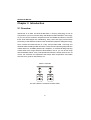
ARS-2017E
Mirror Smart Ultra160
User’s Manual
Version: 1.1
Copyright © 2005 ACARD Technology Corp.
Release: September 2005
Copyright and Trademarks
The information in this manual is subject to change without prior notice and
does not represent a commitment on the part of the vendor, who assumes
no liability or responsibility for any errors that may appear in this manual.
ACARD and SCSIDE® are the trademarks of ACARD Technology Corp. IBM
is the trademark of International Business Machine Corporation. Microsoft
and the Windows Logo are the registered trademarks, and Windows is the
trademark of Microsoft Corporation. All brands and trademarks are the properties of their respective owners.
This manual contains materials protected under International Copyright Conventions. All rights reserved. No part of this manual may be reproduced in
any form or by any means, electronic or mechanical, including photocopying, without the written permission of the manufacturer and the author. All
inquiries should be addressed to ACARD Technology Corp.
Table of Contents
Chapter 1 About SCSIDE® ............................................................ 4
1.1 Revolutionary Technology................................... 4
1.2 SCSIDE® Design ................................................... 5
Chapter 2 Introduction....................................... 6
2.1
2.2
2.3
2.4
2.5
2.6
2.7
2.8
Overview ............................................................... 6
Features ................................................................ 7
RAID System Spec ............................................... 7
SCSI/IDE Interface Spec ...................................... 7
Dimension & Temperature ................................... 8
Package ................................................................ 8
Quick Start ............................................................ 8
HDD Compatibility................................................ 9
Chapter 3 The Control Panel ........................... 12
3.1 LCD Panel ........................................................... 12
3.2 LCD Operation .................................................... 12
3.3 Mirror Smart’s LEDs ........................................... 18
Chapter 4 Hardware Installation ..................... 21
4.1 System Requirement.......................................... 21
4.2 Install ARS-2017E............................................... 21
4.2.1 Attentions ...................................................................... 21
4.2.2 IDE Hard Drive Connection .......................................... 22
4.2.3 External Power Connection.......................................... 24
4.2.4 External Cable Connection ........................................... 24
4.3 DIP Switch Setting ............................................. 26
Chapter 5 Troubleshooting ............................. 28
Appendix 1 Migrate Existing HDD to Mirror .. 33
Appendix 2 Mirror Smart Utility ...................... 35
Appendix 3 SCSI Adapter Compatibility ........ 49
Technical Support Form ................................... 50
ARS-2017E Manual
Chapter 1 About SCSIDE®
1.1 Revolutionary Technology
SCSIDE® is a revolutionary technology developed by ACARD Technology Corp. It
can transform IDE data into SCSI type, and save the expenditures. Through this
technology any inexpensive IDE device can have high-performance SCSI
applications. The following examples are some of the SCSIDE® applications.
1. To transform an IDE hard drive into an external SCSI one for notebook and desktop
PC users to back up data.
2. To transform an IDE CD/DVD drive into a SCSI one.
3. To daisy chain multiple SCSIDE® DVD-ROMs to create a DVD-ROM server.
4. To transform a DMA 133/100/66 hard drive of 5400rpm or 7200rpm into an LVD
SCSI one for PC, Unix workstations and servers.
The basic structure of SCSIDE® is ROC (RAID On Chip), which highly integrates
multiple CPUs. This ROC design is resulting from ACARD’s years of experiences in
the design of IDE, SCSI and RISC CPU chips. The block diagram on the next page
shows that ROC has multiple CPUs. Its ROM, RAM, DMA controllers and external
ROM interface can be used as the firmware update of flash ROM. ACARD has a
perfect firmware technology, too. It makes the transformation of IDE to SCSI an
actual “plug and play”. The firmware has been tested on almost all brands of IDE
DMA 133/100/66 hard drives and ATAPI CD/DVD drives. Whether your IDE device
is an ATA hard drive, or any of the ATAPI CD/DVD drives, you can all plug it and
enjoy the advantages of SCSI with ease. With the intelligent firmware design, you
don’t need to install a driver into the operating system to use SCSIDE® products. In
the operating system it is just like a SCSI device.
4
ARS-2017E Manual
1.2 SCSIDE® Design
The objectives of SCSIDE® design are described as follows:
1. Save the expenditures of SCSI by using an inexpensive IDE device.
2. Create applications like SCSI CD-ROM and high speed SCSI DVD-ROM.
3. Apply ”plug and play” to the transformation of IDE device to SCSI one. It is not
necessary to install a driver.
Welcome to be a new member of SCSIDE® and have a good time.
5
ARS-2017E Manual
Chapter 2 Introduction
2.1 Overview
ARS-2017E is an Ultra 160 SCSI-to-IDE RAID 1 mirroring subsystem. It has an
LCD panel for you to set, monitor easily and adopts ACARD’s SCSIDE® technology,
so you can connect it with the inexpensive ATA 133/100/66 hard drives to achieve
those SCSI advantages like multitasking, daisy chain and highly efficient data
processing. Inside ARS-2017E there is the newest ROC (RAID On Chip) technology,
which contains the RAID function in a chip, and provides RAID 1 mirroring and
automatic data rebuilding to IDE hard drives. These functions provide great protection
of data. Moreover, ACARD’s patented “Dr. Swaptson”, a mechanical design ejecting
a failed hard drive, brings effort-free administration; that is, you can do hot swap
and rebuild data without a key. That operational interface is exactly ease-of-use. Of
course, the automatic fan adjustment that keeps lower temperature and stable
environment is good for data backup, too.
RAID 1 Controller
D0
D1
D0
D1
Dn
Dn
The same data are recorded into both HDDs
6
ARS-2017E Manual
2.2 Features
n
n
n
n
n
n
n
n
n
n
n
n
n
n
n
n
Supports RAID 1 mirroring
Supports real time rebuilding (up to 2.5GB per minute)
Supports hot swap
Supports multitasking
LCD panel for setting, monitoring system and hard drive status
Supports ROC SCSIDE® engine
Minimized CPU utilization
Supports ATA 133/100/66 hard drives
Supports “Big Drive” technology (a hard drive over 137GB)
Patented “Dr. Swaptson” design to eject a failed hard drive
Supports alarm warning for failed system and hard drive
LED indicators for system status
Supports alarm-off resetting button
Automatic fan adjustment to keep a stable environment
Aluminum & steel heat sink frame design
Supports multiplatform operating systems like Windows 98/ME/2000/XP/
Server 2003, Linux, Mac OS, Sun Solaris and Free BSD
2.3 RAID System Spec
n
n
n
n
Supports RAID 1 mirroring to secure data
High availability for mission critical application
Intelligent mechanics for a failed hard drive (effort-free administration)
Supports real time rebuilding
2.4 SCSI/IDE Interface Spec
n
n
n
n
Ultra160 SCSI interface up to 160MB/s of transfer rate
Ultra DMA mode up to 133MB/s of transfer rate
Selectable SCSI ID from 0 to 15
Supports IDE hard drives for hot swap
7
ARS-2017E Manual
2.5 Dimension & Temperature
Dimension
Length: 28cm / Width: 18cm / Height: 19cm
Temperature
–5°C ~ 60°C for non-operation
0°C ~ 40°C for operation (not condensed)
2.6 Package
Open the package of ARS-2017E, and check its contents. If there is anything missing,
contact your distributor.
n
n
n
n
n
n
n
n
ARS-2017E
×1
Support CD (firmware, utility)
User’s manual
Power cord
×1
×1
×1
Plastic stick (to loosen the tray’s handle)
×2
×1
× 1 (optional)
AEC-67160/67162 Ultra160 SCSI adapter × 1 (optional)
External Ultra160 SCSI LVD cable
External Ultra160/320 terminator
2.7 Quick Start
Step 1: Prepare 2 hard drives of the same model, and set the jumper as
Cable Select or Single/Master mode.
Step 2: Take the 2 trays out of ARS-2017E.
Step 3: Put a hard drive into each tray, and connect it with the internal IDE cable
and power cord. Fasten the hard drive with screws.
Step 4: Put the 2 trays back to ARS-2017E.
Step 5: Make sure that the auto-eject handles on the trays are closed.
Step 6: Set a proper and unique SCSI ID for ARS-2017E (on page 27).
Step 7: Connect ARS-2017E to the SCSI card with a SCSI cable. And be sure to
add a terminator to the end. See Chapter 4 for the connection.
Step 8: Connect ARS-2017E with a power cord.
8
ARS-2017E Manual
Step 9: Power on the PC and ARS-2017E.
Step 10: After powering on, the SCSI card will detect a hard drive named Mirror
Smart. Before using, partition and format if it is new.
2.8 HDD Compatibility
ARS-2017E is particularly designed for DMA hard drives. It fully supports the following
brands of DMA 133/100/66 hard drives. It is recommended to set the jumper as
“Master/Single” or “Cable Select” in order to quicken the start of a hard drive. ARS2017E is also compatible with various kinds of SCSI cards, and can operate well in
Mac OS and Linux.
Seagate Barracuda 7200.7 ST320082 200GB
Seagate Barracuda 7200.7 ST3160021A 160GB
Seagate Barracuda 7200.7 ST3160023A 160GB
Seagate Barracuda 7200.7 ST3120026A 120GB
Seagate Barracuda 7200.7 ST3120022A 120GB
Seagate Barracuda 7200.7 ST380011A 80GB
Seagate Barracuda 7200.7 ST340014A 40GB
Seagate Barracuda 5400.1 ST340015A 40GB
Seagate Barracuda 5400.1 ST340015AC 40GB
Seagate Barracuda IV ST380021A 80GB
Seagate Barracuda IV ST360021A 60GB
Seagate Barracuda IV ST340016A 40GB
Seagate Barracuda IV ST320011A 20GB
Seagate Barracuda V ST3120023A 120GB
Seagate Barracuda V ST3120024A 120GB
Seagate Barracuda V ST380023A 80GB
Seagate Barracuda V ST360015A 60GB
Seagate Barracuda V ST340017A 40GB
Maxtor MaXLine II 5A300J0 300GB
Maxtor MaXLine II 5A250J0 250GB
Maxtor MaXLine Plus II 5Y250P0 250GB
9
ARS-2017E Manual
Maxtor DiamondMax Plus9 6Y200P0 200GB
Maxtor DiamondMax Plus9 6Y160P0 160GB
Maxtor DiamondMax Plus9 6Y160J0 160GB
Maxtor DiamondMax Plus9 6Y120L0 120GB
Maxtor DiamondMax Plus9 6Y120P0 120GB
Maxtor DiamondMax Plus9 6Y080L0 80GB
Maxtor DiamondMax Plus9 6Y080P0 80GB
Maxtor DiamondMax Plus9 6Y060L0 60GB
Maxtor DiamondMax Plus16 4R160J0 160GB
Maxtor DiamondMax Plus16 4R160L0 160GB
Maxtor DiamondMax Plus16 4R120L0 120GB
Maxtor DiamondMax Plus16 4R080L0 80GB
Maxtor DiamondMax Plus16 4R080J0 80GB
Maxtor DiamondMax Plus16 4R060L0 60GB
Maxtor DiamondMax Plus16 4R060J0 60GB
Maxtor DiamondMax Plus8 6E040L0 40GB
Maxtor DiamondMax Plus8 6E030L0 30GB
Hitachi 7K250 HDS722525VLAT80 250GB
Hitachi 7K250 HDS722516VLAT20 160GB
Hitachi 7K250 HDS722516VLAT80 160GB
Hitachi 7K250 HDS722512VLAT20 120GB
Hitachi 7K250 HDS722580VLAT20 80GB
Hitachi 7K250 HDS722540VLAT20 40GB
Hitachi 180GXP IC35L180AVV207 185.2GB
Hitachi 180GXP IC35L120AVV207 123.5GB
Hitachi 180GXP IC35L080AVV207 82.3GB
Hitachi 180GXP IC35L06AVV207 60.4GB
Hitachi 180GXP IC35L030AVV207 30.7GB
Hitachi 120GXP IC35L120AVVA07 123.52GB
Hitachi 120GXP IC35L100AVVA07 102.93GB
Hitachi 120GXP IC35L080AVVA07 82.34GB
Hitachi 120GXP IC35L060AVVA07 61.49GB
Hitachi 120GXP IC35L040AVVA07 41.17GB
10
ARS-2017E Manual
Hitachi 60GXP IC35L060AVER07 61.49GB
Hitachi 60GXP IC35L040AVER07 41.17GB
Hitachi 60GXP IC35L030AVER07 30.73GB
Hitachi 75GXP DTLA-307075 76.86GB
Hitachi 75GXP DTLA-307060 61.49GB
Hitachi 75GXP DTLA-307045 46.11GB
Hitachi 75GXP DTLA-307030 30.73GB
Hitachi 40GV DTLA-305040 41.17 GB
Hitachi 40GV DTLA-305030 30.73 GB
Western Digital WD2500JB 250GB
Western Digital WD2500BB 250GB
Western Digital WD2000JB 200GB
Western Digital WD2000BB 200GB
Western Digital WD1800JB 180GB
Western Digital WD1800BB 180GB
Western Digital WD1600JB 160GB
Western Digital WD1600BB 160GB
Western Digital WD1200JB 120GB
Western Digital WD1200BB 120GB
Western Digital WD1000JB 100GB
Western Digital WD1000BB 100GB
Western Digital WD800JB 80GB
Western Digital WD800BB 80GB
Western Digital WD600JB 60GB
Western Digital WD600BB 60GB
Western Digital WD400JB 40GB
Western Digital WD400BB 40GB
Please visit http://www.acard.com to get the newest support list of hard drives.
If your hard drive is not approved by ACARD, contact us or the distributor.
11
ARS-2017E Manual
Chapter 3 The Control Panel
3.1 LCD Panel
There are 4 buttons on the LCD panel of ARS-2017E.
▲ : to scroll up the functions or menus.
▼ : to scroll down the functions or menus.
ENT : to confirm a setting and enter the selected function.
ESC : to cancel a setting and return to the previous layer of functions. Pressing ESC
for more than 2 seconds will let the system return to standby mode.
3.2 LCD Operation
Besides the connection with PC via a SCSI cable, ARS-2017E is an independent
system, too. After pressing the switch on the back of ARS-2017E for seconds, you
can turn on the Mirror Smart. In the standby mode, LCD will display the information
of ARS-2017E such as capacity, status, temperature, fan speed, etc. by turns. Press
ENT or ESC to operate. ARS-2017E is shipped without setting a password, but you
can set one under “SETUP” menu. If you have set a password, key in the correct
password to enter.
There are 5 major function menus in ARS-2017E as the following structure figures
show. Each menu has submenus. Before operation, it is suggested to read through
for understanding.
12
ARS-2017E Manual
1: SYSTEM INFO
1.1: Mirror info
1.2: Disk0 info
1.3: Disk1 info
1.4: Health info
1.1.1:
Vendor ID
Model ID
1.2.1:
Vendor ID
Model ID
1.3.1:
Vendor ID
Model ID
1.4.1:
Disk0 temp.
Fan rpm
1.1.2:
Revision
SCSI max speed
1.2.2:
Revision
IDE max speed
1.3.2:
Revision
IDE max speed
1.4.2:
Disk1 temp.
Fan rpm
1.1.3:
Status Capacity
1.2.3:
Status Capacity
1.3.3:
Status Capacity
1.4.3:
System temp.
Fan rpm
2: SETUP
2.1: Mirror Opt.
2.2: Health Opt.
2.3: Display Opt.
2.1.1:
Max SCSI speed
2.2.1:
Fan detect
2.3.1:
Standby time
2.1.2:
Max IDE speed
2.2.2:
Fan autocontrol
2.3.2:
Page switch rate
2.1.3:
Rebuild rate
2.2.3:
W a rning T(°C/°F)
2.3.3:
Info update rate
2.1.4:
Auto compare
2.2.4:
W a rning alarm
2.3.4:
Temperature unit
2.1.5:
Read balance
2.3.5:
Key tone
13
ARS-2017E Manual
3: ADVANCED SETUP
3.1: Mirror size
3.2: Compare
3.3: Scan disk0
3.5: Unlock disk0
3.7: Password
3.1.1:
Set maximum
3.2.1:
Disk0 primary
Disk1 secondary
3.7.1:
Enable password
3.1.2:
Extend size
3.2.2:
Disk0 secondary
Disk1 primary
3.7.2:
Set password
3.4: Scan disk1
3.6: Unlock disk1
3.8: Advanced
status
4: EVENT LOG
4.1: Display log
4.2: Erase log
4.3: Elapse time
5: LOAD DEFAULT
The detailed explanations for all functions are given below.
1.SYSTEM INFO : the system information
Press ▲ or
1.1
▼ to display the information of the previous or the next page.
Mirror info : the informaiton of mirrored hard drives
Display the disk array’s firmware version, SCSI speed, status and capacity.
1.2
Disk0 info : the information of the upper hard drive
Display the upper hard drive’s brand, model, firmware version, IDE speed,
status and capacity.
14
ARS-2017E Manual
1.3
Disk1 info : the informaiton of the lower hard drive
Display the lower hard drive’s brand, model, firmware version, IDE speed,
status and capacity.
1.4
Health info : the health status of the system
Display the hard drive temperature, the system temperature, the fan speed
of the trays, and the fan speed of the system.
2.SETUP : the settings of the system configuration
Press ▲ or ▼ to change the option. Press ENT to choose the setting that you
want to change. Before returning to the main menu, the system will ask if you
want to save the changed setting.
2.1
Mirror Opt. : the RAID configuration
2.1.1 Max SCSI speed : set the highest speed limit of SCSI
Options are ASYNC, 10, 20, 40, 80, 160 MB/s. Default is 160MB/s.
2.1.2 Max IDE speed : set the highest speed limit of IDE
Options are ATA33, ATA66, ATA100, ATA133. Default is ATA133.
2.1.3 Rebuild rate : set data rebuilding rate
Options are Slow, Normal, Fast. Default is Normal.
2.1.4 Auto compare : compare the two hard drives’ contents automatically
This function enables automatic comparison of data after rebuilding.
2.1.5 Read balance : read the two hard drives’ data by turns
This function lets each hard drive’s data be read for one minute in order
to lengthen the hard drive’s life.
2.2
Health Opt. : the setting of the system environment
2.2.1 Fan detect : detect the movement of a fan
This function lets the system produce a warning and show a message
whenever the fan is abnormal. Default is Enable.
2.2.2 Fan autocontrol : control a fan automatically
The system will adjust the speed of a fan automatically according to the
warning temperature. When temperature is low enough, the fan won’t move,
and so the speed will display “OK”.
2.2.3 Warning T(°C/°F) : set the warning temperature
If the system temperature is over the set value, there will be a blinking on
15
ARS-2017E Manual
the screen to warn the system manager, and so the temperature will be
recorded to the event log.
2.2.4 Warning alarm : enable warning alarm
When the system becomes abnormal, the buzzer will be activated to warn
the system manager.
2.3
Display Opt. : the setting of LCD
2.3.1 Standby time : set the time for the system to return to standby mode
If the system idle time is over the set value, the system will return to
standby mode.
2.3.2 Page switch rate : set the rate of information switching
It is to set the interval rate of displaying information in standby mode.
2.3.3 Info update rate : set the rate of information update
It is to set the update rate of the system status.
2.3.4 Temperature unit : set the unit of temperature
It is to set the temperature unit as °C or °F.
2.3.5 Key tone : set the sound of key pressing
It is to enable or disable the sound of key pressing.
3.ADVANCED SETUP : the settings of the advanced functions
Press ▲ or ▼ to change the option. Press ENT to confirm your option.
3.1
Mirror size : the setting of Mirror capacity
3.1.1 Set maximum : set the maximum capacity
3.1.2 Extend size : extend the size of Mirror
When the two hard drives of the original system have been changed, and
the capacity is bigger than the present Mirror, you are allowed to execute
this function to extend the size of Mirror. The newly increased capacity will
be indicated by the second partition.
3.2
Compare : compare the data
It is to compare if the two hard drives’ data are the same. During comparison if there is any difference, the system will start to rebuild the remaining
data from the primary hard drive to the secondary one. Once this function is
activated, the menu will change to “Stop compare” automatically so that the
system manager can stop comparison.
16
ARS-2017E Manual
3.3
Scan disk0 : scan the upper hard drive
It is to scan if the the upper hard drive is all right. During the scanning,
the system will ask if you want to continue scanning when it detects a failed
track in the hard drive. Once this function is activated, the menu will
change to “Stop scan disk0” automatically so that the system manager can
stop scanning.
3.4
Scan disk1 : scan the lower hard drive
It is to scan if the lower hard drive is all right. During the scanning, the
system will ask if you want to continue scanning when it detects a failed
track in the hard drive. Once this function is activated, the menu will change
to “Stop scan disk1” automatically so that the system manager can stop
scanning.
3.5
Unlock disk0 : eject the upper hard drive
3.6
Unlock disk1 : eject the lower hard drive
3.7
Password : the setting of a password
3.7.1 Enable password : enable the protection of a password
Once you activates the protection of a password, the system will ask
you to key in the password.
3.7.2 Set password : set a new password
Key in the old password, then key in a new password, and confirm the
new password once again to finish the change. If you don’t activate the
protection of a password, the menu will be hidden.
3.8
Advanced status : the status of advancement
It is to display the scanning or rebuilding or comparing progress. The
progress will be displayed in standby mode, too. If there is no task
progressing in the system, the menu will be hidden.
4.EVENT LOG : the recording of events
Press ▲ or ▼ to change the option. Press ENT to confirm your option.
4.1
Display log : display all records (record limit is 100)
4.2
Erase log : erase all records
4.3
Elapse time : display all the time from system start to the present
If the system hasn’t been restarted over 3 years, the counting will be
from the beginning again.
17
ARS-2017E Manual
5.LOAD DEFAULT : recover the defaults
Once the defaults are restored, your all settings, including the password will be
deleted.
The explanations of characters and icons:
(1) Ch0 : the upper hard drive
(2) Ch1 : the lower hard drive
(3) R/W : the hard drive’s reading/writing status
(4) W : the hard drive’s writing status
(5) S : during the scanning of hard drive
(6)
: temperature
(7)
: fan
(8) RB0>1 : data are being rebuilt from disk0 to disk1
(9) RB0<1 : data are being rebuilt from disk1 to disk0
(10) CP0>1 : compare the 2 hard drives’ data by taking disk0 as primary
(11) CP1<1 : compare the 2 hard drives’ data by taking disk1 as primary
3.3 Mirror Smart’s LEDs
The table below explains ARS-2017E’s 5 LEDs and an alarm-off resetting button.
No
LED
Explanation
A1, B1 Hard drive power LED
Its stable green light means normal power
supply.
A2, B2
Hard drive access LED
Its light means busy reading/writing
A3, B3
Hard drive error or
malfunction LED
It blinks when the data is being rebuilt, the track
fails, the fan is abnormal, or the temperature is
too high.
C1
System power LED
Its stable green light means normal power
supply.
C2
Rebuilding LED
It lights when the data is being rebuilt.
C3
Alarm-off resetting button
It can be pushed to stop the buzzing completely.
18
ARS-2017E Manual
Press here to lock
A1
A2
A3
C1
C2
B1
C3
B2
B3
Attention :
l
After installing the hard drives onto the trays, return the trays to their
original position, and push the handles to “Lock” so that the system won’t
act wrongly.
l
During normal operation, if the system detects a failed hard drive, Alarm
LED A3 or B3 will blink 10 seconds. Then, it will keep lighting with handle
ejected. It shows that the failed drive needs to be examined or replaced.
l
After a new drive is installed and plugged, the system will examine the
new drive. Now, LED A1, B1 and C1 will keep lighting. Alarm LED A3 or
B3 will blink to show that the new hard drive is being examined.
l
When the new hard drive is ready, LED A1, B1 and C1 will keep lighting,
and Alarm LED A3 or B3 will keep blinking. Yet, LED A2, B2 and C2 will light
to show that the system is rebuilding data to the new hard drive.
l
The beep of warning is different according to different condition. When there
is a problem happening, please judge and solve the problem in accordance
with the following table.
19
ARS-2017E Manual
Item
Problem description
Buzzer
LED
1
Fan failure
A short beep per 8 seconds
Alarm LED lights with beep
2
High temperature
Three short beeps per 8
seconds
Alarm LED lights with beep
3
Bad sector in HDD
Two short beeps per 8
seconds
Alarm LED blinks per 0.5 second
4
HDD failure
Beep in one second and
mute in the next second,
lasting 10 seconds
Alarm LED blinks per 0.5 second
5
HDD capacity smaller
than the mirror size
A long beep and then 2
short beeps
Alarm LED lights with beep
6
HDD rebuilding
None
Both of HDD Rebuild LEDs light;
target HDD Alarm LED glitters
7
Completion of
rebuilding
A long beep
Alarm LED "OFF"
8
HDD comparsion
None
Access LED blinks per 0.5
second
9
Completion of
comparsion
A short beep and then a
long beep
Access LED "OFF"
If you want to change the mirroring hard drive manually, unlock the handle of the
tray first, then wait 10 seconds for the hard drive to write back the data stored in the
cache. After the beep stops, remove the tray lightly by drawing the handle, and then
take the hard drive.
20
ARS-2017E Manual
Chapter 4 Hardware Installation
4.1 System Requirement
At first, be sure that there is a 68pin LVD SCSI interface in your
External
connector
Internal
connector
computer for connecting ARS-
PCI Slot
2017E. If there is none, buy one
like ACARD’s AEC-67160/67162,
and install its driver.
4.2 Install ARS-2017E
The installation of ARS-2017E
Figure 4-1
includes IDE hard drive connection,
power connection, and cable connection.
4.2.1 Attentions
l
Use Ultra DMA 133/100/66 HDD of the same brand and model to let
ARS-2017E perform better.
l
In installation, put the smaller drive onto the upper tray and the bigger
drive onto the lower tray if the two hard drives are different in capacity.
ARS-2017E will take the smaller drive as the source drive to synchronize
the data.
l
If the two hard drives are the same in capacity, ARS-2017E will take the
drive in the upper tray as the source drive to synchronize the data.
l
If you want to take the current hard drive which contains data as the source
drive, you need to put it into ARS-2017E first. Then, only after the power
LED lights can you put the destination or new drive into ARS-2017E.
l
In rebuilding, it is prohibited to remove any drive, or data will be lost.
21
ARS-2017E Manual
l
In replacing a hard drive, be sure that ARS-2017E is ON, or the new
drive might be regarded as source drive, and the data in the old drive
might be covered.
4.2.2 IDE Hard Drive Connection
Before connecting an IDE hard drive to the tray of ARS-2017E, you need to set the
hard drive as “Master” or “Cable Select” mode by adjusting the jumper setting. If the
hard drive contains important data, please back up your data first, and then put the
hard drive into the tray so as to ensure the highest data security. Besides, if you
want to install the current hard drive which contains OS into ARS-2017E in order to
boot the OS there, see Appendix 1.
SCSI Connectors
DIP Switch
Power Switch
Power Cord Connector
HDD Tray
The auto-eject handle of the tray
Figure 4-2
22
ARS-2017E Manual
Before connecting an IDE hard drive to the tray, power off the system first, and then
follow the steps below to connect.
Step 1: Insert the enclosed plastic stick into the loophole to loosen the handle.
Step 2: Hold the handle to pull out the tray.
loophole
Step 1
Figure 4-3
Step 2
NOTICE: The handle is a switch controlling the hard drive power. Don’t
open it arbitrarily during operation otherwise it may cause data loss.
Step 3: Connect the IDE cable and 4-pin power connector to the IDE hard drive.
Step 4: Screw the hard drive, and replace the tray.
4-pin power connector
Step 3
Step 4
pin 1 of the IDE cable
23
Figure 4-4
ARS-2017E Manual
4.2.3 External Power Connection
After connecting the IDE hard drive to the tray of ARS-2017E, you can connect the
power cord as shown below.
Power Cord
Figure 4-5
4.2.4 External Cable Connection
Connect one ARS-2017E
Step 1: Connect one end of the LVD SCSI cable to the SCSI adapter’s external
connector, and another end to ARS-2017E’s external SCSI connector.
Step 2: Add a terminator to ARS-2017E’s another SCSI connector.
Terminator
Step 1
Step 2
Figure 4-6
24
ARS-2017E Manual
Daisy chain of ARS-2017Es
Step 1: Connect one end of the LVD SCSI cable to the SCSI adapter’s external
connector and another end to ARS-2017E’s external SCSI connector.
Step 2: Connect another SCSI cable to ARS-2017E’s another SCSI connector.
Step 3: Add a terminator to the last ARS-2017E.
Step 1
2
1
Another LVD SCSI cable
Step 2
Terminator
2
1
Step 3
Figure 4-7
25
ARS-2017E Manual
4.3 DIP Switch Setting
The DIP switch setting gives a unique SCSI ID number to the Mirror Smart 160. The
figure shows the DIP switch of ARS-2017E.
ON
1
2
3
4
5
6
7
8
Figure 4-8
Please follow the instructions below to set DIP switch properly.
Give a unique SCSI ID number to each ARS-2017E in a daisy chain according to
the following figure. Even if there is only one ARS-2017E, you still need to give it an
ID number.
1 èON-SCSI ID 1
ON
è
è
ON
1
2
3
4
5
6
7
8
OFF
Default: All OFF (ID=0)
2 èON-SCSI ID 2
3 èON-SCSI ID 4
4 èON-SCSI ID 8
5 èReserve
6 èReserve
7 èReserve
Figure 4-9
8 èReserve
For the illustration of SCSI ID number in ARS-2017E, please see Figure 4-10 on
the next page.
26
ARS-2017E Manual
The SCSI ID number in ARS-2017E is illustrated below.
ID=0
(Default)
ON
ON
ON
1
ID=2
ID=1
2
3
4
5
6
7
8
ON
1
ID=3
2
3
4
5
6
7
8
3
4
5
6
7
8
3
4
5
6
7
8
ON
ON
1
ID=4
2
3
4
5
6
7
1
8
ID=5
ON
2
ON
ON
1
ID=6
4
5
6
7
8
1
ID=7
2
3
4
5
6
7
ID=9
ON
2
3
4
5
6
7
8
N/A
(reserved for host adapter)
ON
ON
1
ID=11
ON
ID=12
2
3
4
5
6
7
8
1
ID=13
ID=14
3
4
5
6
7
8
1
ID=15
6
7
8
2
3
4
5
6
7
8
2
3
4
5
6
7
8
3
4
5
6
7
8
ON
ON
ON
2
5
ON
ON
1
4
ON
ON
2
3
ON
ON
1
2
ON
ON
1
2
8
ON
1
ID=10
3
ON
1
ID=8
2
3
4
5
6
7
1
8
Figure 4-10
27
2
ARS-2017E Manual
Chapter 5 Troubleshooting
If you have any problem in using ARS-2017E, you can try to solve it by referring to
the methods below. But if you still cannot solve, fill in the technical support form at
the end of the manual, and send to us.
1. SCSI card could not detect Mirror Smart
l
Confirm if Mirror Smart and every hard drive were connected well, and the
power switch is ON.
l
Confirm if Mirror Smart was connected firmly to the SCSI card by the SCSI
cable.
l
l
l
Confirm if a terminator was added to the end of the SCSI bus.
Confirm if the ID of Mirror Smart or a SCSI device is unique.
Confirm if every hard drive’s jumper was set to Master/Single or Cable
Select.
2. SCSI card detected an unknown device or a wrong HDD
Usually it is because that Mirror Smart hasn’t connected with any hard drive.
Accordingly, the device which the SCSI card detected is Mirror Smart’s
controller. As for the detection of a wrong hard drive, it is perhaps that the
SCSI cable is bad, or the hard drive is not in the support list. Visit ACARD’s
Web site to get the newest support list, or download the newest firmware of
Mirror Smart to support.
3. Mirror Smart produced an unknown beep or its handle ejected
You can judge the cause according to the length or frequency of a beep.
Refer to Chapter 3. As for the ejecting of handle, it means that a hard drive
failed. Remove it and examine if it still could be used with the scanning &
mending program offered by the manufacturer. But if it couldn’t be used,
get a new one. Mirror Smart will rebuild the data into the new hard drive
automatically. If there are other problems such as fan failure, high temperature, etc., contact the distributor or ACARD’s technical personnel.
28
ARS-2017E Manual
4. An error happened in accessing Mirror’s hard drives or no access
l
l
Confirm if the connection of Mirror Smart and SCSI cable is loose.
Confirm if the quality of SCSI cable and that of terminator are good enough.
ARS-2017E communicates with the SCSI card by 160MB/s of transfer rate,
so if the SCSI cable or terminator is bad, the communication will be unstable. Whenever there is a problem happening, try to lower the transfer
rate to verify if it is the problem of SCSI cable. Please choose a SCSI
cable and a terminator carefully.
l
If the problem is the hard drive, try to get another one, and set Mirror Smart
again.
5. Update the firmware of Mirror Smart and change the mirror size
Refer to Appendix 2.
6. OS didn’t detect Mirror Smart’s hard drives
l
Confirm if the SCSI card has been correctly installed (see the following
steps 1 to 3).
l
If the installation of driver is correct, please confirm if Device Manager has
detected the disk of Mirror Smart (see step 4).
l
If the hard drive is new, and hasn’t been partitioned and formatted, initialize
it with the disk management tool (see step 5).
29
ARS-2017E Manual
Step 1. Right-click “My Computer” to choose “Manage”.
Figure 5-1
Step 2. Enter “Computer Management” to choose “Device Manager”.
Figure 5-2
30
ARS-2017E Manual
Step 3. In “Device Manager” double click “SCSI and RAID controllers” to examine if
the driver of SCSI card has been correctly installed.
Figure 5-3
Step 4. In “Device Manager” double click “Disk drives” to confirm if the system has
detected the disk of Mirror Smart.
Figure 5-4
31
ARS-2017E Manual
Step 5. Add a new partition for the hard drive of Mirror Smart in the “Disk Management” so as to access the new hard drive.
Figure 5-5
32
ARS-2017E Manual
Appendix 1 Migrate Existing HDD to Mirror
1. Migrate the current IDE HDD (No. A for storing data) into Mirror Smart to
form a new mirroring disk
Step 1. Take two empty trays out of Mirror Smart.
Step 2. Put HDD A into one of the trays, install it and replace to Mirror Smart.
Step 3. Connect Mirror Smart to SCSI card according to section 2.3.
Step 4. Boot Mirror Smart and computer. Be sure that Mirror Smart’s hard drive
power LED is normal (stable green light). Begin to access the data of SCSI
hard drive formed by mirroring according to the user’s manual of SCSI card.
Step 5. Put the newly purchased HDD D into another tray, install it and replace to
Mirror Smart. Now Mirror Smart will copy the data of HDD A into HDD D.
During rebuilding, any access won’t affect the rebuilt data.
2. Migrate the current IDE HDD (No. B having the OS for booting) into Mirror
Smart, and boot from the HDD on Mirror Smart
Step 1. Before migrating HDD B into Mirror Smart, back up the important data of
HDD B at first. Then, boot from HDD B to enter the OS, and install the driver
of SCSI card to verify if the OS can identify Mirror Smart.
Step 2. Shut down. Remove HDD B from the IDE port. Then, put HDD B into one of
the trays, install it and replace to Mirror Smart.
Step 3. Connect Mirror Smart to SCSI card according to section 2.3.
Step 4. Boot Mirror Smart and computer. Be sure that Mirror Smart’s hard drive
power LED is normal (stable green light).
Step 5. Enter BIOS on the motherboard to set the priority of booting from SCSI
device to the highest. Exit after saving the setting.
Step 6. Under normal circumstances, after rebooting you can enter OS and access
the hard drive successfully.
Step 7. Put the newly purchased HDD D into another tray, install it and replace to
Mirror Smart. Now Mirror Smart will copy the data of HDD B into HDD D.
During rebuilding, any access won’t affect the rebuilt data.
This method is fit for most PC systems and Windows platforms. If you cannot boot
33
ARS-2017E Manual
from the OS on HDD B according to the above steps, or the OS is other than Windows like Linux or Mac, etc., try the third method.
3. Install a new IDE HDD (No. C newly purchased or fine) and a new OS (such
as Windows XP) into Mirror Smart
Step 1. Take two empty trays out of Mirror Smart.
Step 2. Put HDD C and HDD D into the trays, install them and replace to Mirror
Smart separately.
Step 3. Boot Mirror Smart and computer. Be sure that Mirror Smart’s hard drive
power LED is normal (stable green light).
Step 4. After booting, if everything is right and the two hard drives are equal in
capacity, Mirror Smart will regard the hard drive on the upper tray as the
source and that on the lower tray as the destination, and begin to synchronize.
Step 5. Enter BIOS to set the priorities of booting from CD-ROM and SCSI hard
drive to the first and second. Exit after saving the setting.
Step 6. Put the CD containing OS installation into CD-ROM and boot hence. Before
installing the OS, install the driver of SCSI card first if necessary.
Step 7. After installing the OS, install the Mirror Smart Utility to monitor the whole
mirror.
NOTICE: In a set of Mirror Smart you are suggested to use two hard drives
of the same brand and model. If you replace a failed hard drive with a new
one, the new hard drive should be larger or equal to the original one.
34
ARS-2017E Manual
Appendix 2 Mirror Smart Utility
The Mirror Smart Utility is used to manage and control ARS-2017E. With it you can
easily set, change and examine all things concerning the situation of hard drives.
After entering the utility, if you want to change some basic settings, you can click
“Setup” and select “Preference” as shown below.
35
ARS-2017E Manual
The main items in “Preference” are explained as follows.
1.
2.
3.
4.
5.
1. Set the time to update the status of Mirror Smart.
2. Set the time interval to update the event log.
3. Set the compare speed.
4. Set to pop up the main window when an error occurs.
5. Set to show the main window when the program is running.
36
ARS-2017E Manual
If you want to set the functions of Mirror Smart, you can click “Setup” and select
“Mirror Smart Setup” as shown below.
37
ARS-2017E Manual
The main items in “Mirror Smart Setup” are explained as follows.
3.
9.
7.
1.
4.
2.
5.
6.
8.
10.
1. Set the balance reading (each drive per minute).
2. Set the warning alarm to indicate a failed system.
3. Set the fan detection.
4. Set the auto control of fan speed.
5. Set the alarm reset button.
6. Set the auto compare (after rebuilding).
7. Set the rebuilding rate.
8. Set the max.IDE speed.
9. Set the max. SCSI speed.
10. Set the warning temperature.
38
ARS-2017E Manual
If you want to change the size of Mirror Smart, you can click “Setup” and select
“Extend Mirror Size” as shown below.
1.
2.
1. Set a new size equal to or larger than the current one.
2. Set the maximum size.
If the current size is the maximum size, you cannot change the size again.
39
ARS-2017E Manual
If you want to update the firmware of Mirror Smart, you can click “Setup” and select
“Update Firmware” as shown below.
1.
2.
3.
1. The current F/W version.
2. Update to the newest version.
3. Click “Open” and then “Yes” to
confirm.
40
ARS-2017E Manual
If you want to receive a mail when system or a hard drive fails, you can click “Setup”
and select “Mail Notification Setup” as shown below. Then, in “Mail Setup” be sure
that Enable mail notification is activated. And type related data in the following three
rows: 1. SMTP server, 2. User account, 3. Sender Email.
1.
2.
3.
41
ARS-2017E Manual
Then click “Supervisor”, and type the receiver’s mail address in the row near to the
bottom. After clicking “Add”, the address will be added to the list.
Finally click “Event Filter”, and choose one or more than one events for which you
will send a mail to notify the supervisor. There are six events for choice: 1. HDD
failed, 2. HDD is removed, 3. HDD is inserted, 4. Fan failed, 5. HDD over heat, 6.
HDD rebuilding/compare.
1.
2.
3.
4.
5.
6.
42
ARS-2017E Manual
If you want to know the version of Mirror Smart Utility, you can click “About!”.
Click “Status List” to see the status of Mirror Smart.
2.
1.
1. Host Bus ID No. and the SCSI adapter.
2. Target ID No. and the Mirror Smart.
43
ARS-2017E Manual
Click “Mirror Info” to see all information of the hard drives and the status of Mirror.
4.
5.
6.
1.
7.
2.
8.
9.
10.
3.
11.
12.
1. The system’s firmware version, capacity, status, SCSI bus speed as one HDD.
2. The HDD’s frimware version, capactiy, status, IDE bus speed in the upper tray.
3. The HDD’s frimware version, capacity, status, IDE bus speed in the lower tray.
4. Scan the HDD.
5. Compare the two HDDs’ data.
6. See information of other Mirror Smarts.
7. The fan in the upper tray (failed).
8. The temperature of the HDD in the upper tray (too high).
9. Eject the HDD in the upper tray.
10. The fan in the lower tray (nomal).
11. The temperature of the HDD in the lower tray (normal).
12. Eject the HDD in the lower tray.
44
ARS-2017E Manual
Click “Compare HDDs” to see if the Source HDD and the Target HDD contain the
same data. The percentage bar on the bottom of the figure shows the process of
comparison or rebuilding.
45
ARS-2017E Manual
If you didn’t install a hard drive, or the system didn’t detect it, the status will be
shown as the figure.
46
ARS-2017E Manual
If you want to read the record of an event log, click “Open Event Log” under “Event
Log”. Then, choose the file you need.
47
ARS-2017E Manual
Click the file to read as the following figure shows.
The “Event Log” describes the time and status when an event happens. It is helpful
for you to solve the problems.
48
ARS-2017E Manual
Appendix 3 SCSI Adapter Compatibility
Generally speaking, a SCSI adapter can be compatible with ARS-2017E if they
meet the SCSI operation protocol. All the SCSI adapters listed below are compatible with ARS-2017E.
ACARD AEC-67160
ACARD AEC-67162
Adaptec ASC 29160
Adaptec ASC 39160
Adaptec AHA 2940U2W
Adaptec AHA 2940UW
Initio 9100UW
Tekram DC-390U2W(53C895)
Tekram DC-390U3W
Tekram 390UF LSI Symbios 53C875 Ultra Wide SCSI Controller
If your SCSI adapter cannot be compatible wtih ARS-2017E, fill in the technical
support form on the next page and send to us for quick service.
49
ARS-2017E Manual
Technical Support Form
Email: [email protected]
http://www.acard.com
Model: ARS-2017E
*F/W Version:
System Configuration
Motherboard *
BIOS version
SCSI adapter *
Chipset
Memory
Display card
Other I/O card *
OS version *
Hard Disk
Tray 1
Tray 2
Brand *
Model *
Capacity *
Problem description * :
Required columns are marked with asterisks (*) .
50