1
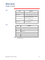
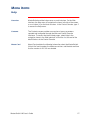
MasterSwitch VM
Power Distribution Unit
AP9222
AP9222EXP
User’s Guide
Thank You!
Thank you for selecting the APC MasterSwitch VM (vertical-mount)
power distribution unit (PDU). It has been designed for many years of
reliable, maintenance-free service. APC is dedicated to the
development of high-performance electrical power conversion and
control products. We hope that you will find this product a valuable,
convenient addition to your system.
Please read this manual! It provides important configuration and
operating instructions that will help you get the most from your
MasterSwitch VM power distribution unit. See the Installation and Quick
Start Manual included with MasterSwitch VM and on this CD for more
detailed information on installing and setting up the unit.
MasterSwitch VM
Contents
Introduction . . . . . . . . . . . . . . . . . . . . . . . . . . . . . . . . . 1
Product Description . . . . . . . . . . . . . . . . . . . . . . . . . . . . . 1
MasterSwitch VM—1
MasterSwitch VM Controller—2
LEDs—3
Operating MasterSwitch VM . . . . . . . . . . . . . . . . . . . . . . . 4
Initial setup—4
Configuring outlets for operation—4
Current sensing—9
Overload Outlet Restrictions—9
Overload Audible Alarm—9
Low Current Threshold—9
Managing MasterSwitch VM . . . . . . . . . . . . . . . . . . . .
10
Management Interfaces . . . . . . . . . . . . . . . . . . . . . . . . . 10
Overview—10
Web interface—10
Control Console interface—11
SNMP interface—12
Auto-configuring MasterSwitch VM—12
Password-Protected Accounts . . . . . . . . . . . . . . . . . . . . . 13
Overview—13
Account access to outlets and menu items—13
Menu Items . . . . . . . . . . . . . . . . . . . . . . . . . . . . . . . . .
14
Outlets . . . . . . . . . . . . . . . . . . . . . . . . . . . . . . . . . . . . . 14
Control actions—14
Synchronization set configuration—15
MasterSwitch VM . . . . . . . . . . . . . . . . . . . . . . . . . . . . . . 16
Unit Configuration—16
Outlet Configuration—17
Outlet Configuration: Lnks—17
MasterSwitch VM User’s Guide
iii
Contents
Event Log. . . . . . . . . . . . . . . . . . . . . . . . . . . . . . . . . . . . 18
Event Log—18
Accessing the Event Log
using the FTP interface—18
Retrieving the Event Log
using the FTP interface—19
Viewing the Event Log—19
Deleting an Event Log in the FTP interface—19
Network . . . . . . . . . . . . . . . . . . . . . . . . . . . . . . . . . . . . . 20
TCP/IP—20
TFTP/FTP—20
Telnet/Web—21
SNMP—21
SNMP: Access Control—21
SNMP: Trap Receiver—22
System . . . . . . . . . . . . . . . . . . . . . . . . . . . . . . . . . . . . . . 23
User Manager—23
Outlet User Manager—24
Identification—25
Date/Time—25
File Transfer—25
Tools—26
Links—26
Help . . . . . . . . . . . . . . . . . . . . . . . . . . . . . . . . . . . . . . . . 27
Overview—27
Contents—27
Interactive Assistant—27
About Card—27
Security. . . . . . . . . . . . . . . . . . . . . . . . . . . . . . . . . . . .
28
Security Features . . . . . . . . . . . . . . . . . . . . . . . . . . . . . . 28
Planning and implementing security features—28
Port assignments—28
User names, passwords and community names—
28
Authentication . . . . . . . . . . . . . . . . . . . . . . . . . . . . . . . . 29
Authentication versus encryption—29
MD5 authentication (Web interface)—29
Summary of access methods—30
MasterSwitch VM User’s Guide
iv
Contents
Product Information . . . . . . . . . . . . . . . . . . . . . . . . . .
31
Warranty Information . . . . . . . . . . . . . . . . . . . . . . . . . . 31
Limited warranty—31
Obtaining service—31
Warranty limitations—31
Troubleshooting . . . . . . . . . . . . . . . . . . . . . . . . . . . . . . . 32
If problems persist—32
Life-Support Policy . . . . . . . . . . . . . . . . . . . . . . . . . . . . . 33
General policy—33
Examples of life-support devices—33
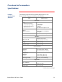
Specifications . . . . . . . . . . . . . . . . . . . . . . . . . . . . . . . . . 34
Product specifications (AP9222)—34
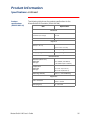
Product specifications (AP9221NX166)—35
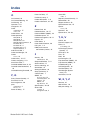
Index
APC Worldwide Technical Support
MasterSwitch VM User’s Guide
v
MasterSwitch VM
Introduction
Product Description
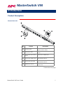
MasterSwitch VM
No.
Feature
Description
!
Switched outlet
Provides individually managed
power control to outlets.
"
Outlet status LED
Indicates the state of the switched
outlet.
#
Overcurrent alarm silence
button
Silences the audible alarm.
$
Overcurrent audible alarm
Alerts you to an overload on the
MasterSwitch VM unit.
%
Overcurrent alarm LED
Indicates an overload on the
MasterSwitch VM unit.
&
Modular ports (RJ11)
Connects a unit to the controller or to
another unit.
Continued on next page
MasterSwitch VM User’s Guide
1
Introduction
Product Description continued
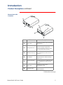
MasterSwitch VM
Controller
No.
Feature
Description
Status LED
Indicates the status of the connection
with the unit.
"
Configuration Port
Connects the unit to a serial port on a
device running the appropriate
terminal emulation software in order
to access the Control Console.
#
Modular port (RJ11)
Connects the unit to an Ethernet LAN
for configuration or remote access
control.
$
Reset Button
Re-initializes the MasterSwitch VM
network interface without affecting
outlet state.
%
10Base-T network
&
Status LED
Indicates the status of the
management card.
'
Link-RX/TX LED
Indicates the status of the Ethernet
LAN connection.
!
port
Connects the unit to an Ethernet LAN
for configuration or remote access
control.
Continued on next page
MasterSwitch VM User’s Guide
2
Introduction
Product Description continued
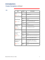
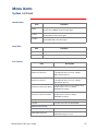
LEDs
LED
MasterSwitch VM
Outlets
page 1, Item 2
MasterSwitch VM
Overcurrent Alarm
page 1, Item 5
MasterSwitch VM
Controller
Front Status
Status
Description
On
The Outlet is on.
Off
The Outlet is off.
Off
The unit has no power.
Green
The unit is operating under normal load
conditions.
Flashing
green
The unit is approaching its maximum load.
(Warning threshold exceeded)
Solid red
The unit has exceeded its maximum load.
(>100%)
On
The Controller has power.
Off
The Controller has no power.
Off
The unit has no power.
page 2, Item 1
Solid green
The unit has valid network settings.
MasterSwitch VM
Controller
Rear Status
Flashing
green
The unit does not have valid network
settings.
page 2, Item 6
Solid red
A hardware failure has been detected in the
unit.
Blinking
Red (Slow)
The unit is making BOOTP requests.
MasterSwitch VM
Controller Rear
Link-RX/TX
Off
The device which connects the unit to the
network (whether a router, hub, or
concentrator) is off or not operating
correctly.
page 2, Item 7
Flashing
Green
The unit is receiving data packets from the
network.
MasterSwitch VM User’s Guide
3
Introduction
Operating MasterSwitch VM
Initial setup
You must configure the network settings of MasterSwitch VM before it
can operate on a network. The required settings are:
• IP address of MasterSwitch VM
• Subnet Mask
• IP address of the default gateway
Note: If a default gateway is not present, enter an IP address
of a computer on the same subnet that is always active.
For instructions on configuring the MasterSwitch VM network settings,
see the installation manual included with the unit and on the CD. After
you have configured MasterSwitch VM, no further configuration is
required. The remaining MasterSwitch VM properties are pre-configured
at the factory. However, you may want to customize these properties for
your application. See Menu Items on page 14 for more details on
changing MasterSwitch VM properties.
Configuring
outlets for
operation
MasterSwitch VM allows you to configure an outlet for on-demand
operation. On-demand operation consists of On, Off, and Reboot Outlet
Control Actions. The sections that follow desribe each operation that
you can configure for your MasterSwitch VM unit.
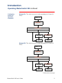
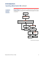
Immediate On. This action immediately turns an outlet on.
Immediate Off. This action immediately turns an outlet off.
Immediate Reboot. This action immediately turns an outlet off, and
then turns it back on after the outlet’s Reboot Duration expires.
Outlet is on
Immediate Reboot
command is issued
Outlet is turned off
MasterSwitch VM User’s Guide
Cancel command
is issued
Reboot Duration
Outlet remains
off
Outlet is turned
on
expires
4
Introduction
Operating MasterSwitch VM continued
Configuring
outlets for
operation,
continued
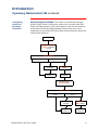
Delayed On. This action turns on an outlet according to its Power On
Delay.
Outlet is off
Delayed On
command is issued
Power On Delay
Never
Delay
Cancel command
is issued
Power On Delay
Outlet remains
off
Outlet is turned
on
expires
Delayed Off. This action turns off an outlet according to its Power Off
Delay.
Outlet is on
Delayed Off
command is issued
Power Off Delay
Never
Delay
Cancel command
is issued
Power Off Delay
Outlet remains
on
Outlet is turned
off
expires
Continued on next page
MasterSwitch VM User’s Guide
5
Introduction
Operating MasterSwitch VM continued
Configuring
outlets for
operation,
continued
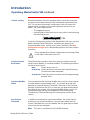
Delayed Reboot. This action turns an outlet off after the outlet’s Power
Off Delay expires. Once the outlet’s Reboot Duration expires, the outlet
is turned on.
Outlet is on
Delayed Reboot
command is issued
Power Off Delay
Never
Delay
Cancel command
is issued
Power Off Delay
Outlet remains
on
Outlet is turned off
expires
Cancel
command is
issued
Reboot
Duration
Outlet
remains off
Outlet is
turned ons
expires
Continued on next page
MasterSwitch VM User’s Guide
6
Introduction
Operating MasterSwitch VM continued
Configuring
outlets for
operation,
continued
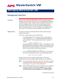
Sequenced Reboot. This action is available only through Master Outlet
Control. Initiating this action immediately powers off all outlets. Each
outlet will wait the longest Reboot Duration time (in seconds) in the set
of outlets on a MasterSwitch VM unit plus its own Power On Delay.
When these two delays expire, the outlet will be turned on.
Outlet is on
Sequenced Reboot†
command is issued
Outlet is turned off
Longest Reboot
Duration expires
Power On Delay
Never
Delay
Cancel command
is issued
Power On Delay
Outlet
remains off
Outlet is
turned ons
expires
Continued on next page
MasterSwitch VM User’s Guide
7
Introduction
Operating MasterSwitch VM continued
Configuring
outlets for
operation,
continued
Delayed Sequenced Reboot. This action is available only through
Master Outlet Control. Initiating this action turns off outlets after their
Power Off Delay expires. Once all the outlets on the unit are turned off,
each outlet will wait the longest Reboot Duration time in the set of
outlets plus its own Power On Delay. When these two delays expire, the
outlet will be turned on.
Outlet is on
Delayed Sequenced
Reboot† command
is issued
Power Off Delay
Never
Delay
Cancel command
is issued
Power Off Delay
Outlet
remains on
Outlet is
turned offs
expires
Longest Reboot
Duration expires
Power On Delay
Never
MasterSwitch VM User’s Guide
Delay
Cancel command
is issued
Power On
Delay expires
Outlet
remains off
Outlet is
turned ons
8
Introduction
Operating MasterSwitch VM continued
Current sensing
Each MasterSwitch VM unit is equipped with a sensor that measures
the total current being used by the unit and devices connected to the
unit. The current measurement is displayed on the first screen that
appears when you log on and is used to generate alarms that you
define. The values displayed are:
• The aggregate current
• A percentage of the branch circuit rating, which is derived using
the following formula:
In the Unit Configuration section of the MasterSwitch VM menu, you can
define Overload Outlet Restrictions, conditions that generate an
Overload Audible Alarm, and the Low Current Threshold. (See Unit
Configuration on page 16 for a detailed description of the items listed in
the menu.)
Do not exceed the maximum voltage and current ratings listed
on the label on the back of the unit.
Overload Outlet
Restrictions
Outlet Restrictions prevents users from turning on outlets when the
current sensor detects an overload condition. The following restrictions
can be set for each unit:
None
Outlets always turn on.
On Warning Outlets do not turn on when the Overload Warning
Threshold has been exceeded.
On Overload Outlets do not turn on when the full load percentage
exceeds 100%.
Overload Audible
Alarm
You can customize the Overload Audible Alarm so that it never sounds,
it sounds when the load exceeds 100%, or it sounds when the load
exceeds its Overload Warning Threshold. The value for the Overload
Warning Threshold can be set at a value that you determine based on
the needs of your system. If the Overload Audible Alarm is set to On
Overload Warning and the load exceeds the Overload Warning
Threshold, the Overload Warning LED flashes green and the alarm
sounds.
Low Current
Threshold
In addition to monitoring for overload conditions, the current sensor
monitors for low-current conditions. If current drops below the Low
Current Threshold that you have defined, the unit generates an SNMP
trap to alert the host computer.
Note:
MasterSwitch VM User’s Guide
This item is available only in the SNMP interface.
9
MasterSwitch VM
Managing MasterSwitch VM
Management Interfaces
Overview
After you have configured MasterSwitch VM with the proper network
settings (see Initial setup on page 4), you can manage MasterSwitch VM
remotely through its Web, Control Console, and SNMP interfaces.You
can also manage locally on the Control Console through a serial
connection. Only one user at a time can access MasterSwitch VM.
Serial connections (using a terminal emulator) have precedence over
Telnet users, and Telnet users have precedence over Web users.
Web interface
To access and log on to the MasterSwitch VM unit’s Web interface
perform these steps:
In the URL Location field, do one of the following:
•
If the MasterSwitch VM unit’s Web port is set to the default
value of 80, type http:// followed by the MasterSwitch VM
unit’s IP address. The following example shows a typical IP
address:
http://170.241.17.51
•
If the MasterSwitch VM Web port is set to a value other than the
default of 80, enter the System IP address (the IP address of the
MasterSwitch VM unit) followed by a colon and the configured
Web Port value (8000 in the following example):
http://170.241.17.51:8000
•
You can also enter the DNS name—this requires a DNS server
entry for the MasterSwitch VM unit. See the example below:
http://MasterSwitchVM25
Respond to the username and password prompts. The default
Administrator user name and password are both apc, all lowercase.
Note: You can change the user name, password, and time-out values
in the System menu. See User Manager on page 23 and Outlet
User Manager on page 24 for more information.
Note: Some Web interface features (data verification, APC Interactive
Assistant, and MD5 authentication) require that you enable
JavaScript and/or Java. In order for MD5 to function properly
you must also have cookies enabled on your Web browser.
Continued on next page
MasterSwitch VM User’s Guide
10
Managing MasterSwitch VM
Management Interfaces continued
Control Console
interface
In addition to using the Web, you can also manage MasterSwitch VM
through the Control Console by one of the following modes of access:
•
•
Telnet, for remote management
A serial connection, for local management.
Telnet. To access the MasterSwitch VM unit’s Control Console using
Telnet:
1. Start a Telnet session and choose Remote System from the
Connect pull-down menu.
2. Type in the IP address of the MasterSwitch VM unit.
3. Click on the Connect button.
Serial connection. To access the Control Console using a serial
connection:
1. Use the supplied configuration cable (APC part number 9400024C) to connect your serial port to the configuration port on
the MasterSwitch VM Controller.
2. Set the terminal port for the following communication settings:
Item
Setting
Baud Rate
2400
Data Bits
8
Stop Bits
1
Parity
None
Handshaking
None
Local Echo
Off
Terminal Type
ANSI (VT100)
Logging on. The procedure for logging on to the Control Console is the
same for both Telnet and a serial connection; respond to the user name
and password prompts.The default values of Administrator name and
password are both apc, all lowercase. You can change the username,
password and time-out values through the System menu. See User
Manager on page 23.
Structure. All menus in the Control Console list items by number and
name. To select an item, type in the number and press ENTER. For
menus that configure values, always use the Accept Changes option to
save any changes you have made.
Continued on next page
MasterSwitch VM User’s Guide
11
Managing MasterSwitch VM
Management Interfaces continued
SNMP interface
MasterSwitch VM fully supports SNMP—all unit and outlet properties
are configurable through SNMP. For instructions on how to use SNMP to
manage MasterSwitch VM, see the Mibguide.pdf file in the Snmp folder
on the CD.
Auto-configuring
MasterSwitch VM
Unit properties, outlet properties, and user accounts can be downloaded
to MasterSwitch VM from a configuration file. For details on autoconfiguring your MasterSwitch VM unit(s), open the README.txt file in
the apcConfigUtility directory on the CD. You can also find additional
information on the I2C utility on page 15 of the Management Card
Addendum.pdf located on the CD.
MasterSwitch VM User’s Guide
12
Managing MasterSwitch VM
Password-Protected Accounts
Overview
MasterSwitch VM provides three types of password-protected accounts
that allow you to control access to the MasterSwitch VM unit. Each type
of account provides a different level of access to the management
menus. There is one Administrator account, one Device Manager
account, and up to 16 Outlet User accounts.
Account access to
outlets and menu
items
Administrator and Device Manager accounts have access to all outlets.
Each Outlet User only has access to the outlets assigned to his or her
account. The Administrator account can configure and manage all other
accounts. For instructions on configuring Device Manager and Outlet
User accounts, see User Manager on page 23 and Outlet User Manager
on page 24.
Account Type
MasterSwitch VM
Main Menu Items
Administrator
Device
Manager
Outlet
User
Outlets
Yes
Yes
Yes
MasterSwitch VM
Yes
Yes
No
Event Log
Yes
Yes
No
Network
Yes
No
No
System
Yes
No
No
Logout
Yes
Yes
Yes
Help
Yes
Yes
Yes
Links
Yes
Yes
Yes
MasterSwitch VM User’s Guide
13
MasterSwitch VM
Menu Items
Outlets
Control actions
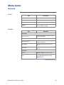
Outlet Control Actions may be performed on individual outlets (by
Individual Outlet Control) or on all accessible outlets as a group (by
Master Outlet Control). A Control Action can only be applied to an outlet
that is not executing a command. If there is a command pending, the
State will be displayed orange.
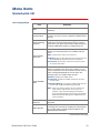
Item
Definition
Immediate On
Turns outlet on.
Immediate Off
Turns outlet off.
Immediate Reboot
Turns off the outlet immediately, waits the outlet’s Reboot
Duration time, and turns the outlet back on. For further
explanation, see the Immediate Reboot sequence diagram on
page 4.
Delayed On
Turns on the outlet according to its Power On Delay. For further
explanation, see the Delayed On sequence diagram on page 5.
Delayed Off
Turns off the outlet according to its Power Off Delay. For further
explanation, see the Delayed Off sequence diagram on page 5.
Sequenced
Reboot†
Delayed Reboot
Delayed
Sequenced
Reboot†
Immediately powers off all outlets. Each outlet waits the longest
Reboot Duration time plus its own Power On Delay and then
turns on.
Note: The longest Reboot Duration is the longest Reboot
Duration (in seconds) in the set of outlets.
Turns an outlet off after the outlet’s Power Off Delay expires.
Once the outlet’s Reboot Duration expires, the outlet is turned
on. For further explanation, see the Delayed Reboot sequence
diagram on page 7.
Turns off each outlet after its Power Off Delay. Once the outlets
are turned off, each outlet waits the longest Reboot Duration
time plus its own Power On Delay. When this delay expires, the
outlet turns on.
Note: The longest Reboot Duration is the longest Reboot
Duration (in seconds) in the set of outlets.
Cancel all pending commands for the outlet(s).
Cancel
Note: Outlet State is displayed in orange with an asterisk (*)
when a command is pending for the outlet(s).
† Applies only when using Master Outlet Control
Continued on next page
MasterSwitch VM User’s Guide
14
Menu Items
Outlets continued
Synchronized set
configuration
Outlets that are members of a synchronization set will all execute the
same control action simultaneously (within 16 milliseconds). In a
configuration where multiple redundant power cords are being used in a
daisy-chain configuration, this feature permits synchronized switching
across units.
When you configure a synchronization set, you can assign an outlet to
only one set, and all the outlets in a specified set assume the
characteristics of the lowest numbered outlet. If you make changes to
any of the outlets in a given set, all of the outlets will take on the new
characteristics.
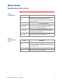
Item
Definition
Set Number
Identifies a specific set of outlets.
Member Outlets
Identifies the outlets assigned to a given set.
Note:
In the Outlets menu, you can identify the synchronization set to
which an outlet belongs by the number in brackets. For
example:
(unit #: outlet # [synchronization set #])
MasterSwitch VM User’s Guide
15
Menu Items
MasterSwitch VM
Unit Configuration
Item
Definition
Name
Name of the MasterSwitch VM unit (23 characters
maximum).
Cold Start Delay
The time that MasterSwitch VM will delay in applying power
to outlets, once the AC power is applied to the MasterSwitch
VM unit.
Overload Warning
Threshold
The percentage of a full load that will trigger an overload
warning. An overload warning will cause the overcurrent
alarm LED to flash green and sound the audible alarm (if the
overload audible alarm property is configured to do so).
The overload conditions, if any, that will prevent outlets from
turning on. The following actions are available under this
item:
Overload Outlet
Restrictions
None—Always allow outlets to be turned on.
On Warning—Do not allow outlets to be turned on when the
Overload Warning Threshold has been exceeded.
On Overload—Do not allow outlets to be turned on when
the load exceeds 100%.
The overload conditions, if any, that will cause the audible
alarm to sound. Once the alarm starts sounding, you can
use the mute button to turn off the alarm or you can clear the
alarm; selecting Disabled will not clear the alarm. The
following actions are available under this item:
Disabled—Disables the audible alarm.
Overload Audible
Alarm
On Overload—Sounds the audible alarm when the load
exceeds 100%.
On Overload Warning—Sounds the audible alarm when the
load exceeds the Overload Warning Threshold.
Note: When you change settings, the new setting is not
used until the next time the event occurs. For
example, if the overload warning Threshold has
been exceeded and the setting is then changed from
On Overload to On Warning, the audible alarm will
not be activated.
Low Current
Threshold
The threshold for load current below which an SNMP trap is
generated..
Reboot Duration
Longest reboot duration in the set of accessible outlets. You
can change this value only by modifying the reboot duration
of accessible outlets. Used by Sequenced Reboot and
Delayed Sequenced Reboot.
Continued on next page
MasterSwitch VM User’s Guide
16
Menu Items
MasterSwitch VM continued
Outlet
Configuration
Outlet
Configuration:
Links
.
Item
Definition
Outlet
Identifies each outlet, the unit to which the outlet is
connected, and the synchronization set to which it belongs.
This information appears in the following form: unit #:outlet #
[synchronization set #]
Name
Identifies each outlet (23 characters maximum).
Power On Delay
The time that the outlet waits before turning on after the
command is issued. Used by Delayed On, Sequenced
Reboot, and Delayed Sequenced Reboot.
Power Off Delay
The time that the outlet waits before turning off after the
command is issued. Used by Delayed Off, Delayed Reboot,
and Delayed Sequenced Reboot.
Reboot Duration
The time that the outlet will remain off during a reboot. Used
by Immediate Reboot and Delayed Reboot.
.
Item
Definition
Outlet
Identifies each outlet, the unit to which the outlet is
connected, and the synchronization set to which it belongs.
This information appears in the following form: unit #:outlet #
[synchronization set #]
Name
Identifies the outlet (23 characters maximum).
Link
Defines HTTP links to relevant Web sites.
MasterSwitch VM User’s Guide
17
Menu Items
Event Log
Event Log
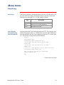
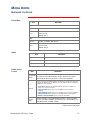
The Event Log displays the MasterSwitch VM unit’s last 300 events. You
can view the Event Log by selecting the Event Log menu in the Web
interface or by pressing CTRL + L in the Control Console.
Item
Accessing the
Event Log using
the FTP interface
Description
Date
Date the event occurred (DD/MM/YYYY)
Time
Time the event occurred (HH:MM:SS)
Event
Description of the event.
You can retrieve the Event Log using client side FTP. (For example, from
an MS-DOS prompt, type ftp card-ip where card-ip is the IP address of
your MasterSwitch VM unit.) After logging into the unit's FTP server, type
dir. You will see a listing similar to the following:
ftp>dir
200 Command okay.
150 Opening data connection for /.
--wx-wx-wx 1 apc apc 262144 Jul 23 2000
aos253.bin
--wx-wx-wx 1 apc apc 458752 Jul 23 2000
msp202.bin
-r--r--r-- 1 apc apc 4096 Jul 29 2000 event.txt
226 Closing data connection.
ftp: 194 bytes received in 0.00Seconds
194000.00Kbytes/sec.
ftp>
Continued on next page
MasterSwitch VM User’s Guide
18
Menu Items
Event Log continued
Retrieving the
Event Log using
the FTP interface
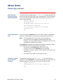
To retrieve the Event Log, type get event.txt. The MasterSwitch VM
unit will transmit the Event Log to your specified drive. The unit ensures
that at least the last 300 events will be transmitted. You will see a list
similar to the following:
ftp>get event.txt
200 Command okay.
150 Opening data connection for event.txt
226 Closing data connection.
ftp: 3694 bytes received in 0.11Seconds
33.58Kbytes/sec.
ftp>
Viewing the Event
Log
After retrieving the event.txt file, you can view it using a spreadsheet.
The file is TAB delimited so it will format automatically into columns.
Note: The MasterSwitch VM unit always uses four-digit year
representation when logging and displaying event data.
However, you may need to select a four-digit date format in the
spreadsheet to display all four digits.
The event.txt file includes the following information not directly shown
in the Web and Control Console Event Log screens:
• The version of the event.txt file format (first field).
• The Date and Time the event.txt file was retrieved.
• The Name, Contact, Location, and IP address of the unit’s management card.
• An unique Event Code for every type of event.
Deleting an Event
Log in the FTP
interface
To delete the Event Log, type del event.txt. No confirmation is
required. A new event.txt file is created immediately in response to the
Deleted Log event. You will see a list similar to the following:
ftp>del event.txt
250 Requested file action okay, completed.
ftp>
MasterSwitch VM User’s Guide
19
Menu Items
Network
TCP/IP
Item
Description
System IP
The IP address of the unit
Subnet Mask
The network subnet mask
Default Gateway
The local default gateway (router address)
BOOTP
Enables or disables BOOTP requests for
TCP/IP settings at startup.
TFTP/FTP
Item
Definition
TFTP Client
Remote Server IP
The network address of the TFTP server
used for downloads.
FTP Client
Remote Server IP
The network address of the FTP server
used for downloads.
User Name
The user name for access to the FTP
server.
Password
The password for access to the FTP
server.
FTP Server
Access
Enable or Disable FTP server access.
Port
The TCP/IP port on which the FTP server
for the Management Card is located.
Default: port 21
Continued on next page
MasterSwitch VM User’s Guide
20
Menu Items
Network continued
Telnet/Web
Item
Definition
Telnet
Access
Enables or Disables Telnet Access.
Port
The TCP/IP port where the Telnet server for the MasterSwitch VM
unit is located.
Default: port 23
Web
Access
Enables or Disables Web Access.
Port
The TCP/IP port where the Web server for the MasterSwitch VM
unit is located.
Default: port 80
SNMP
.
Item
SNMP: Access
Control
Definition
SNMP Access
Enables or disables SNMP access.
Access Control
Controls access to each of the four SNMP channels.
Trap Receiver
Defines the NMSs (up to 4) to which traps are sent.
Item
Definition
Community
Name
The password that the NMS (identified by the NMS IP option) must use
for SNMP access to MasterSwitch VM. The allowed access type is
defined by the Access Type option (15 characters maximum).
Limits access to the NMS or NMSs specified. You specify the value as a
specific IP address for one NMS or as an IP address filter for multiple IP
addresses. For example:
NMS IP
Access
Type
• 159.215.12.1 allows only the NMS with the specific IP address of
159.215.12.1 to have access.
• 159.215.12.255 allows access for any NMS on the 159.215.12
segment.
• 159.215.255.255 allows access for any NMS on the 159.215 segment.
• 159.255.255.255 allows access for any NMS on the 159 segment.
• 0.0.0.0 or 255.255.255.255 allows access for any NMS.
Defines whether an NMS (identified by the NMS IP option) has Write
access (can GETs and SETs), has Read access (can only GETs), or is
Disabled (cannot use GETs or SETs).
Continued on next page
MasterSwitch VM User’s Guide
21
Menu Items
Network continued
SNMP: Trap
Receiver
Item
Community Name
Receiver NMS IP
MasterSwitch VM User’s Guide
Definition
The password the unit uses when it sends
traps to the NMS identified by the Receiver
NMS IP option (15 character maximum).
The IP address of the NMS that will
receive traps sent by the unit.
Note: To send no traps to any NMS, set
the Trap Receiver IP to 0.0.0.0.
Trap Generation
Enables or disables the ability of the unit
to send traps to the NMS identified by the
Receiver NMS IP option.
Authentication Traps
Enables or disables the ability of the unit
to send authentication traps to the NMS
identified by the Receiver NMS IP.
22
Menu Items
System
User Manager
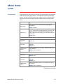
The properties of the Administrator and Device Manager are configured
under the User Manager section. The Administrator has unrestricted
access, but the Device Manager can configure only the MasterSwitch
VM unit; the Device Manager cannot configure Network and System
items.
Item
Auto Logout
Definition
How long a user can be inactive before being logged off
automatically.
Default: 3 minutes.
Authentication
A setting of Basic causes the Web Interface to use standard
HTTP 1.1 login (base64 encoded passwords); MD5 causes the
Web Interface to use an MD5-based authentication login. In
order for MD5 to function properly, you must enable cookies in
your browser.
Default: Basic
Administrator
User Name
Password
User name (10 characters maximum).
Default: apc
Password for HTTP 1.1 authentication only (10 characters
maximum).
Default: apc
Authentication
Phrase
Authentication phrase (for MD5 only). The phrase must be 15
to 32 characters.
Default: admin user phrase
Device Manager User
User Name
Password
User name (10 characters maximum).
Default: device
Password only for HTTP 1.1 authentication (10 characters
maximum).
Default: apc
Authentication
Phrase
Authentication phrase for MD5 only. The phrase must be 15 to
32 characters.
Default: device user phrase
Continued on next page
MasterSwitch VM User’s Guide
23
Menu Items
System continued
Outlet User
Manager
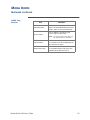
You can create up to 16 independent Outlet User accounts for the
MasterSwitch VM unit. Each Outlet User is assigned a unique user
name, password, description, and an outlet access list, as described
below.
Current Outlet User List. The list shows the existing outlet user
accounts and the outlets to which they have access. To edit an existing
account, click on the underlined user name. To add a user, select Add
New User.
Configure the Outlet User Account Settings. Once you have
selected an Outlet User Account, you can configure or delete an
account. The following table lists and defines the configurable settings
for Outlet User Manager.
Item
User Name
Definition
Outlet user name for both HTTP 1.1 and MD5
authentication (10 characters maximum).
Note: A User Name in orange indicates the
user account has been disabled.
Password
Outlet user password for HTTP 1.1
authentication (10 characters maximum).
Authentication Phrase
Outlet user authentication phrase for MD5
authentication. The phrase must be 15–32
characters.
User Description
Identification/description of the outlet user (30
characters maximum).
Enables, disables, or deletes an outlet’s
account.
Account Status
Note: A disabled account prevents the Outlet
User of the account from logging on.
The User Name appears in orange if
the account has been disabled.
MasterSwitch VM Outlet
Access
Selects the outlets to which users have
access.
Delete User
Delets an outlet’s account.
Continued on next page
MasterSwitch VM User’s Guide
24
Menu Items
System continued
Identification
Item
Definition
Name
The system name used to identify the device. This name will be
used for the sysName OID in the SNMP agent.
Contact
The contact or owner of the device. This will be used for the
sysContact OID in the SNMP agent.
Location
The physical location of the device. This will be used for the
sysLocation OID in the SNMP agent.
Date/Time
Item
File Transfer
Definition
Date
The date for the system in the form of: MM/DD/YY.
Time
The time for the system in the form of: HH:MM:SS (24 hour time).
.
Item
Description
Describe the Current Transfer Settings
Remote TFTP Server IP
The IP address of the remote TFTP server defined
in the Network menu’s TFTP/FTP settings.
TFTP: Remote Server IP
The IP address of the remote FTP server defined
Remote FTP Server IP
in the Network menu’s TFTP/FTP settings.
FTP: Remote Server IP
Remote FTP Server User Name
The user name of the FTP server defined in the
Network menu’s TFTP/FTP settings.
FTP Client: User Name
Remote FTP Server Password
The password of the FTP server defined in the
Network menu’s TFTP/FTP settings.
FTP Client: Password
Configure the Name of the File to Download
Filename
The name of the file to be downloaded
Initiate the File Transfer
Result of Last File Transfer
Displays the result of the last file transfer.
Initiate File Transfer Via
Allows you to choose whether the file will be
transferred using TFTP or FTP
MasterSwitch VM User’s Guide
25
Menu Items
System continued
Tools
.
Item
Definition
No Action
Causes no action
Reboot Card
Restarts the management card operation, but
does not affect MasterSwitch VM outlet states.
Reset Card to Defaults
Reset Card to Defaults
Except TCP/IP
Restores all configuration settings, including
user accounts, to their default.
Warning: This will reset the TCP/IP settings
and enable BOOTP!
Restores all configuration settings (except
TCP/IP) to their defaults.
Links
Item
Definition
Configure each User Link (up to 3)
Name
The link name that will appear on the menu bar.
URL
The HTTP link in URL form: http://mysite.com/
mypage.com.
Configure the APC Links
Name
View the name of an APC link.
URL
Define the URL of each APC link.
Note: The hyperlinks are defined and used only in the MasterSwitch
VM Web interface.
MasterSwitch VM User’s Guide
26
Menu Items
Help
Overview
MasterSwitch provides help menus on each interface. On the Web
interface, the help menu is located on the lower, left side of the screen
or as a button (?) on the black title bars. In the Control Console, type ?
to access the Help menu.
Contents
The Contents screen provides an overview of many parameters
reported and configured through the Web and Control Console
interfaces. To access the internal help pages, select Help in the
navigation frame in the Web interface, or click the ? at the end of the
black title bars in the Control Console.
About Card
About Card provides the following information about the MasterSwitch
VM unit: the serial number, the hardware revision, and the date and time
that the version of APC OS was loaded.
MasterSwitch VM User’s Guide
27
MasterSwitch VM
Security
Security Features
Planning and
implementing
security features
As a network device that passes information across the network, the
MasterSwitch unit is subject to the same exposure as other devices on
the network.
Use the information in this section to plan and implement the security
features appropriate for your environment.
Port assignments
If a Telnet, FTP, or Web server uses a non-standard port, a user must
specify the port when using the client interface, such as a Web browser.
The non-standard port address becomes an extra “password,” hiding
the server to provide an additional level of security. The TCP ports for
which the Telnet, FTP, and Web servers listen are initially set at the
standard “well known ports” for the protocols.To hide the interfaces, use
any port numbers from 5000 to 65535.
User names,
passwords,
community names
All user names, passwords, and community names for SNMP are
transferred over the network as plain text. A user who is capable of
monitoring the network traffic can determine the user names and
passwords required to log in to the Administrator, Device Manager, and
Outlet User accounts of a MasterSwitch unit’s Control Console or Web
interface. This security limitation of the protocols affects any device
using Telnet, a Web server, or an SNMP version 1 agent.
MasterSwitch VM User’s Guide
28
Security
Authentication
Authentication
versus encryption
The MasterSwitch unit controls access by providing basic authentication
through user names, passwords, and IP addresses, but provides no
type of encryption. These basic security features are sufficient for most
environments, in which sensitive data is not being transferred. To
ensure that data and communication between the MasterSwitch unit
and the client interfaces, such as Telnet and the Web browser, cannot
be captured, you can provide a greater level of security by enabling
MD5 authentication (described below) for the Web interface.
MD5
authentication
(Web interface)
The Web interface option for MD5 authentication enables a higher level
of access security than the basic HTTP authentication scheme. The
MD5 scheme is similar to CHAP and PAP remote access protocols.
Enabling MD5 implements the following security features:
•
•
•
The Web server requests a user name and a password phrase
(distinct from the password). The user name and password
phrase are not transmitted over the network, as they are in
basic authentication. Instead, a Java login applet combines the
user name, password phrase, and a unique session challenge
number to calculate an MD5 hash number. Only the hash number is returned to the server to verify that the user has the correct login information; MD5 authentication does not reveal the
login information.
In addition to the login authentication, each form post for configuration or control operations is authenticated with a unique challenge and hash response.
After the authentication login, subsequent page access is
restricted by IP addresses and a hidden session cookie. (You
must have cookies enabled in your browser.) Pages are transmitted in their plain-text form, with no encryption.
If you use MD5 authentication, which is available only for the Web
interface, disable the less secure interfaces, including Telnet, FTP, and
SNMP. For SNMP, you can disable write-only access so that read
access and trap facilities are still available.
Although MD5 authentication provides a much higher level of security
than the plain-text access methods, complete protection from security
breaches is almost impossible to achieve. Well-configured firewalls are
an essential element in an overall security scheme. For additional
information on MD5 authentication, see RFC document #1321 at the
Web site of the Internet Engineering Task Force. For CHAP, see RFC
document #1994.
Continued on next page
MasterSwitch VM User’s Guide
29
Security
Authentication continued
Summary of access
methods
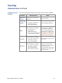
The following table describes each interface and its access methods.
Interface
Serial Control
Console
Security Access
Access is by user name and
password.
Notes
Always enabled.
These methods are available:
Telnet Control
Console
• User name and password
• Selectable server port
• Server Enable/Disable
The user name and password
are transmitted as plain text.
NMS IP filters allow access
These methods are available:
SNMP
•
•
•
•
Community Name
NMS IP filters
Agent Enable/Disable
Four access communities with
read/write/disable capability
from either one IP address or
from multiple IP addresses.
You specify multiple NMSs not
by their literal IP addresses but
in the format of an NMS IP filter.
See SNMP: Access Control on
page 21 for more information.
These methods are available:
FTP Server
• User name and password
• Selectable server port
• Server Enable/Disable
These methods are available:
Web Server
MasterSwitch VM User’s Guide
•
•
•
•
User name and password
Selectable server port
Server Enable/Disable
MD5 Authentication option
Only the Administrator account
has access.
In basic HTTP authentication
mode, the user name and
password are transmitted base64 encoded (with no
encryption). MD5 authentication
mode uses a user name and
password phrase.
30
MasterSwitch VM
Product Information
Warranty Information
Limited warranty
American Power Conversion (APC) warrants MasterSwitch VM to be
free from defects in materials and workmanship for a period of two
years from the date of purchase. Its obligation under this warranty is
limited to repairing or replacing, at its own sole option, any such
defective products. This warranty does not apply to equipment which
has been damaged by accident, negligence, or misapplication or has
been altered or modified in any way. This warranty applies only to the
original purchaser.
Obtaining service
To obtain service under warranty you must obtain a returned material
authorization (RMA) number from APC or a designated APC service
center. Products must be returned to APC or an APC service center with
transportation charges prepaid and must be accompanied by a brief
description of the problem encountered and proof of date and place of
purchase. See If problems persist on page 32 for more information,
including packaging, shipping, and labeling requirements for returned
products.
Warranty
limitations
Except as provided herein, American Power Conversion makes no
warranties, express or implied, including warranties of merchantability
and fitness for a particular purpose. Some jurisdictions do not permit
limitation or exclusion of implied warranties; therefore, the aforesaid
limitation(s) or exclusion(s) may not apply to the purchaser.
Except as provided above, in no event will APC be liable for direct,
indirect, special, incidental, or consequential damages arising out of the
use of this product, even if advised of the possibility of such damage.
Specifically, APC is not liable for any costs, such as lost profits or
revenue, loss of equipment, loss of use of equipment, loss of software,
loss of data, costs of substitutes, claims by third parties, or otherwise.
This warranty gives you specific legal rights and you may also have
other rights which vary from state to state.
MasterSwitch VM User’s Guide
31
Product Information
Troubleshooting
If problems persist
For problems not covered in this manual, or if your problem persists,
follow this procedure:
1. Note the serial number and date of purchase of the
MasterSwitch VM unit. Contact Customer Support at a phone
number or address on the back cover of this user guide (see
APC Worldwide Customer Support on page 38).
2. Be prepared to provide a description of the problem. A
technician will help solve the problem over the phone, if
possible, or will give you a Return Material Authorization (RMA)
number.
3. If the MasterSwitch VM unit is under warranty, repairs or
replacement is free of charge. If the warranty has expired, there
will be a charge for repair or replacement.
4. Pack the MasterSwitch VM unit carefully to avoid damage in
transit. Damage sustained in transit is not covered under the
warranty. Enclose a letter in the package with your name,
address, RMA number, a copy of the sales receipt, daytime
phone number, and check (if applicable).
5. Mark the RMA number clearly on the outside of the shipping
carton. The factory will not accept any materials without this
marking.
6. Return the MasterSwitch VM unit by insured, prepaid carrier to
the address provided by the Customer Support technician.
MasterSwitch VM User’s Guide
32
Product Information
Life-Support Policy
General policy
As a general policy, American Power Conversion (APC) does not
recommend the use of any of its products in life-support applications
where failure or malfunction of the APC product can be reasonably
expected to cause failure of the life-support device or to significantly
affect its safety or effectiveness. APC does not recommend the use of
any of its products in direct patient care. APC will not knowingly sell its
products for use in such applications unless it receives in writing
assurances satisfactory to APC that (a) the risks of injury or damage
have been minimized, (b) the customer assumes all such risks, and (c)
the liability of American Power Conversion is adequately protected
under the circumstances.
Examples of lifesupport devices
The term life-support device includes but is not limited to neonatal
oxygen analyzers, nerve stimulators (whether used for anesthesia, pain
relief, or other purposes), autotransfusion devices, blood pumps,
defibrillators, arrhythmia detectors and alarms, pacemakers,
hemodialysis systems, peritoneal dialysis systems, neonatal ventilator
incubators, ventilators (for adults or infants), anesthesia ventilators,
infusion pumps, and any other devices designated as “critical” by the
U.S. FDA.
Hospital-grade wiring devices and leakage current protection may be
ordered as options on many APC UPS systems. APC does not claim that
units with this modifications are certified or listed as hospital-grade by
APC or any other organization. Therefore these units do not meet the
requirements for use in direct patient care.
MasterSwitch VM User’s Guide
33
Product Information
Specifications
Product
specifications
(AP9222)
The following table shows the product specifications for the
MasterSwitch VM power distribution unit (AP9222).
Item
Specification
Electrical
Input:
Nominal input voltage
Acceptable input voltage
Nominal input frequency
Input connector
100–230 VAC
90–250 VAC
50/60 Hz
IEC 60320-C20 appliance inlet
Output:
Output connectors
8 IEC 60320-C13 individually
Maximum total current draw:
Without loads: 0.2 Amps
managed
Physical
Size (H × W × D)
47.0 x 1.75 x 1.75 in.
(119.38 x 4.45 x 4.45 cm)
Weight:
6.0 lb (2.3 kg)
Shipping weight:
8.0 lb (3.6 kg)
Environmental
Elevation (above MSL):
Operating
Storage
0 to 10,000 ft (0 to 3000 m)
0 to 50,000 ft (0 to 15 000 m)
Temperature:
Operating
Storage
32 to 104° F (0 to 40° C)
32 to 113° F (0 to 45° C)
Operating Humidity:
0 to 95%, non-condensing
Approvals
EMC verification:
FCC Class A, VCCI, CISPR 22
Class A, C-Tick
Safety Agency:
UL, CSA, VDE
Continued on next page
MasterSwitch VM User’s Guide
34
Product Information
Specifications continued
Product
specifications
(AP9221NX166)
The following table shows the product specifications for the
MasterSwitch VM Controller (AP9221NX166).
Item
Specification
Electrical
Input:
Nominal input voltage
24 VDC
Maximum total current draw:
0.1 amp @ 24 VDC
Physical
Size (H × W × D)
1.73 x 5.53 x 6.75 in
(4.39 x 14.0 x 17.3 cm)
Weight:
1.69 lb (.766 kg)
Shipping weight:
4.53 lb (2.05 kg)
Environmental
Elevation (above MSL):
Operating
Storage
0 to 10,000 ft (0 to 3000 m)
0 to 50,000 ft (0 to 15 000 m)
Temperature:
Operating
Storage
32 to 104° F (0 to 40° C)
Operating Humidity:
0 to 95%, non-condensing
32 to 113° F (0 to 45° C)
Approvals
MasterSwitch VM User’s Guide
EMC verification:
FCC Class A, VCCI, CISPR 22
Class A, C-Tick
Safety Agency:
UL, CSA, VDE
35
MasterSwitch VM
Index
Current sensing, 9
Customer support, 32
A
About Card, 27
Accept Changes, 11
Access
by account type, 13
outlet, 24
Access Control (SNMP), 21
Accounts, 13
access, 13
deleting, 24
status, 24
alarm silence button, 1
Authentication, 23, 29
phrase, 24
traps (SNMP), 22
Auto Logout, 23
Auto-Configuration, 12
D, E
Data bits (Control Console), 11
Date, 25
Default Gateway, 20
Delayed Off, 5, 14
Delayed On, 5, 14
Delayed Reboot, 6, 14
Delayed Sequence Reboot, 14
Delayed Sequenced Reboot, 8
Delete account, 24
Delete User, 24
Encryption not supported, 29
Event Log
access, 13
B
Event Log Menu, 18
Baud rate (Control Console), 11
BOOTP, 20
Branch circuit rating, 9
C
Cancel, control action, 14
Cold Start Delay, 16
Communications settings
(Control Console), 11
Community Name (SNMP), 21–
22
FTP interface, 18
viewing, 19
Configuring network settings, 4
Configuring outlets, 17
Configuring unit, 16
ConfigUtility, 12
Contact, 25
Control actions, 14
Control Console interface, 11
Cookies, required for MD5, 10
Current Outlet User List, 24
MasterSwitch VM User’s Guide
J, K, L
Java/JavaScript, 10
Leakage current protection, 33
LEDs, 3
controller, 2
Link-RX/TX, 2
management card, 2
outlet status, 1
Liability, 31
Life-support, 33
Link-RX/TX LED, 2
Links, 17, 26
access, 13
Local Echo (Control
Console), 11
Local management, 11
Location, 25
Low Current Threshold, 9, 16
F, G, H
File Transfer, 25
FTP client/server, 20
Getting started, 4
Handshaking (Control
Console), 11
Help, 27
access, 13
Help Features
About Card, 27
Contents, 27
Interactive Assistant, 27
Configuration port, 2
Configuring
outlets, 4– 9
Initial setup, 4
Interactive Assistant, 10, 27
IP address, setting, 10
Hospital-grade wiring, 33
Hyperlinks, defining, 26
I
Identification, 25
Immediate Off, 4, 14
Immediate On, 4, 14
Immediate Reboot, 5, 14
Individual Outlet Control, 14
M, N
Management interfaces, 10– 11
Managing MasterSwitch
VM, 10– 13
Master Outlet Control, 14
MasterSwitch VM Controller, 2
MasterSwitch VM
menu, 16– 17
access, 13
MD5 authentication, 29
Member Outlets, 15
Menus, 14– 27
Name (outlet), 17
Name (unit), 16
Network
access, 13
Network menu, 20– 22
Network port, 2
Network settings, configuring, 4
NMS IP (SNMP), 21
36
Index
O
On Overload, 16
On Overload Warning, 16
On Warning, 16
Operation, 4– 9
Orange text, 24
Outlet
configuration, 17
control, 14
Outlet Access, 24
Outlet operations
Delayed Off, 5
Delayed On, 5
Delayed Reboot, 6
Delayed Sequenced Reboot, 8
Immediate Off, 4
Immediate On, 4
Immediate Reboot, 5
Sequenced Reboot, 7
outlet status LED, 1
Outlet User Manager, 24
Outlets
access, 13
Outlets menu, 14– 15
Outlets, configuring, 4– 9
overcurrent alarm, 1
Overload Audible Alarm, 9, 16
Overload Outlet Restrictions, 9,
16
Overload Warning Threshold, 16
P, Q
Parity (Control Console), 11
Password, 23– 24
Port assignments, 28
ports
configuration, 2
RJ11, 1– 2
Power Off Delay, 17
MasterSwitch VM User’s Guide
Power On Delay, 17
Preliminary setup, 4
Product description, 1– 3
Product information, 31– 35
R
Reboot Card, 26
Reboot Duration, 16– 17
Receiver NMS IP (SNMP), 22
Redundant power, 15
Remote management, 10– 11
Repairs, 32
Reset button, 2
Reset Card to Defaults, 26
RJ11 port, 1– 2
RMA (return material
authorization) number, 31
S
Security, 28
authentication, 29
Sequenced Reboot, 7, 14
Serial interface, 11
Service, obtaining, 31
Set Number, 15
Setting IP address, 10
Setup, preliminary, 4
silence button, 1
SNMP, 21
Access Control, 21
Community Name, 21
interface, 12
NMS IP, 21
Trap Receiver, 21
Specifications, 34– 35
Status LED
status LED
outlet, 1
Stop bits (Control Console), 11
Subnet Mask, 20
Support, technical, 32
Synchronization sets, 15
System
access, 13
System IP, 20
System menu, 23– 26
T, U, V
TCP/IP, 20
Technical support, 32
Telnet, 11
port settings, 21
Terminal type (Control
Console), 11
TFTP client, 20
Time, 25
Tools, 26
transferring files, 25
Trap Generation (SNMP), 22
Trap Receiver (SNMP), 21
Troubleshooting, 32
Unit Configuration, 16
User Description, 24
User Manager (System
menu), 23
User Name, 23– 24
W, X, Y, Z
Warranty, 31
Web interface, 10
Web port settings, 21
controller, 2
management card, 2
37
APC Worldwide Customer Support
Customer support for this or any other APC product is available at no charge in any of the
following ways:
•
Visit the APC Web site to find answers to frequently asked questions (FAQs), to access
documents in the APC Knowledge Base, and to submit customer support requests.
– http://www.apcc.com (Corporate Headquarters)
Connect by links to APC Web pages for specific countries and regions, each of which
provides customer support information.
– http://www.apcc.com/support/
Submit customer support requests.
•
Contact an APC Customer Support Center by telephone or e-mail.
– Regional centers:
APC Headquarters (U.S. and
Canada)
(1) (800) 800-4272 (toll free)
Latin America
(1) (401) 789-5735 (United States)
[email protected]
Europe, Middle East, Africa
(353) (91) 702020 (Ireland)
[email protected]
Japan
(03) 5434-2021
[email protected]
– Local, country-specific centers: go to http://www.apcc.com/support/contact for
contact information.
•
Contact the APC representative or other distributor from whom you purchased your APC
product for information on how to obtain local customer support.
Entire contents copyright © 2000 American Power Conversion. All rights reserved. Reproduction
in whole or in part without permission is prohibited. APC, MasterSwitch and NetShelter are trademarks or
registered trademarks of American Power Conversion Corporation. All other trademarks,
product names, and corporate names are the property of their respective
owners and are used for informational purposes only.
990-6046
08/2000