1
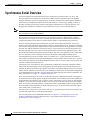
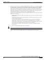
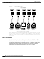
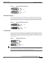
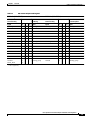
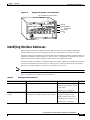
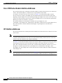
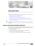
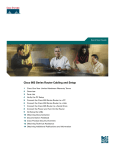
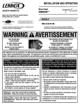
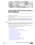
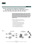
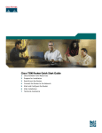
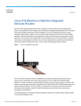
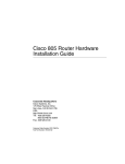
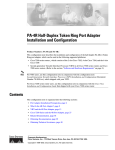
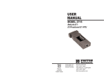
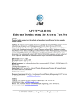
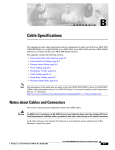
C H A P T E R
1
Overview
This chapter describes the PA-4T port adapter and contains the following sections:
•
Port Adapter Overview, page 1-1
•
Synchronous Serial Overview, page 1-2
•
LEDs, page 1-3
•
Cables, Connectors, and Pinouts, page 1-4
•
Port Adapter Slot Locations on the Supported Platforms, page 1-13
•
Identifying Interface Addresses, page 1-15
Port Adapter Overview
The PA-4T, shown in Figure 1-1, provides four channel-independent, synchronous serial ports that
support full-duplex operation at T1 (1.544 Mbps) and E1 (2.048 Mbps) speeds. Each port supports any
of the available interface types: Electronics Industries Association/Telecommunications Industries
Association (EIA/TIA)-232, EIA/TIA-449, V.35, X.21, and EIA-530. The cable attached to each PA-4T
interface port determines its type (EIA/TIA-232, and so forth) and its mode (DCE or DTE).
Note
Although the VIP supports online insertion and removal (OIR), individual port adapters do not. To
replace port adapters, you must first remove the VIP from the chassis, and then replace port adapters as
required.
Cisco 7200 series routers support OIR of all port adapter types.
Figure 1-1
PA-4T—Faceplate View
H4496
CD
RC
LB
RD
TC
TD
CD
RC
LB
RD
TC
TD
CD
RC
LB
RD
TC
TD
CD
RC
LB
RD
TC
TD
EN
FAST SERIAL
PA-4T Synchronous Serial Port Adapter Installation and Configuration
OL-3560-02
1-1
Chapter 1
Overview
Synchronous Serial Overview
Synchronous Serial Overview
The PA-4T supports the following interface types: EIA/TIA-232, EIA/TIA-449, V.35, X.21, and
EIA-530. EIA/TIA-232, which is by far the most common interface standard in the United States,
supports unbalanced circuits at signal speeds up to 64 kbps. EIA/TIA-449, which supports balanced
(EIA/TIA-422) and unbalanced (EIA/TIA-423) transmissions, is a faster (up to 2 Mbps) version of
EIA/TIA-232 that provides more functions and supports transmissions over greater distances. The
EIA/TIA-449 standard was intended to replace EIA/TIA-232, but it was not widely adopted.
Note
The EIA/TIA standards were referred to as recommended standards called RS-232 and RS-449 prior to
their acceptance by the ANSI committee.
The resistance to convert to EIA/TIA-449 was due primarily to the large installed base of DB-25
hardware and to the larger size of the 37-pin EIA/TIA-449 connectors, which limited the number of
connections possible (fewer than are possible with the smaller, 25-pin EIA/TIA-232 connector).
EIA-530, which supports balanced transmission, provides the increased functionality, speed, and
distance of EIA/TIA-449 on the smaller, DB-25 connector used for EIA/TIA-232. The EIA-530 standard
was created to support the more sophisticated circuitry of EIA/TIA-449 on the large number of existing
EIA/TIA-232 (DB-25) hardware instead of the larger, 37-pin connectors used for EIA/TIA-449. Like
EIA/TIA-449, EIA-530 refers to the electrical specifications of EIA/TIA-422 and EIA/TIA-423. The
specification recommends a maximum speed of 2 Mbps. EIA-530 is used primarily in the United States.
The V.35 interface is most commonly used in the United States and throughout Europe, and is
recommended for speeds up to 48 kbps. The X.21 interface uses a 15-pin connection for balanced
circuits and is commonly used in the United Kingdom to connect public data networks. X.21 relocates
some of the logic functions to the DTE and DCE interfaces and, as a result, requires fewer circuits and
a smaller connector than EIA/TIA-232.
All interface types except EIA-530 can be individually configured for operation with either external
(DTE mode) or internal (DCE mode) timing signals; EIA-530 operates with external timing only. In
addition, all VIP serial interface types support non-return to zero (NRZ) and non-return to zero inverted
(NRZI) format, and both 16-bit and 32-bit cyclic redundancy checks (CRCs). The default configuration
is for NRZ format and 16-bit CRC. You can change the default settings with software commands. (For
more information, see Chapter 4, “Configuring the PA-4T.”)
There is no default mode or clock rate set on the VIP serial ports, although an internal clock signal is
present on all ports for DCE support. Using the internal clock, you can also perform local loopback tests
without having to terminate the port or connect a cable. (All interface types except X.21 DTE support
loopback.) To use the port as a DCE interface, you must set the clock rate and connect a DCE adapter
cable. To use the port as a DTE interface, you need only connect a DTE adapter cable to the port. Because
the serial adapter cables determine the mode and interface type, the PA-4T interface becomes a DTE
when a DTE cable is connected to it.
If a DTE cable is connected to a port with a clock rate set, the DTE ignores the clock rate and uses the
external clock signal that is sent from the remote DCE.
For a brief description of the clock rate command, see Chapter 4, “Configuring the PA-4T.” For
complete command descriptions and instructions, see the publications listed in the “Related
Documentation” section on page vi.
PA-4T Synchronous Serial Port Adapter Installation and Configuration
1-2
OL-3560-02
Chapter 1
Overview
Synchronous Serial Specifications
Synchronous Serial Specifications
The PA-4T provides up to four synchronous serial interfaces. Each interface allows a maximum
bandwidth of 2.048 Mbps; the speed depends on the type of electrical interface used. Use EIA/TIA-232
for speeds of 64 kilobits per second (kbps) and below, and use X.21, EIA/TIA-449, V.35, or EIA-530 for
higher speeds.
Serial signals can travel a limited distance at any given bit rate; generally, the slower the baud rate, the
greater the distance. All serial signals are subject to distance limits beyond which a signal degrades
significantly or is completely lost.
Table 1-1 lists the recommended (standard) maximum speeds and distances for each PA-4T serial
interface type. The recommended maximum rate for V.35 is 2,048 Mbps.
Table 1-1
Standards for Transmission Speed Versus Distance
EIA/TIA-232
Distances
EIA/TIA-449, X.21, V.35, EIA-530
Distances
Rate (bps)
Feet
Meters
Feet
Meters
2400
200
60
4,100
1,250
4800
100
30
2,050
625
9600
50
15
1,025
312
19200
25
7.6
513
156
38400
12
3.7
256
78
56000
8.6
2.6
102
31
1544000 (T1)
–
–
50
15
Balanced drivers allow EIA/TIA-449 signals to travel greater distances than EIA/TIA-232. The
recommended distance limits for EIA/TIA-449 shown in Table 1-1 are also valid for V.35, X.21, and
EIA-530. EIA/TIA-449 and EIA-530 support 2.048-Mbps rates, and V.35 supports 2.048-Mbps rates
without any problems; we do not recommend exceeding published specifications for transmission speed
versus distance. Do so at your own risk.
LEDs
The PA-4T contains the enabled LED, standard on all port adapters, and a one status LED for each port.
After system initialization, the enabled LED goes on to indicate that the PA-4T has been enabled for
operation. The LEDs are shown in Figure 1-2.
LEDs on the PA-4T—Horizontal Orientation Shown
H4491
LB
CD
RC
RD
TC
TD
EN
Figure 1-2
PA-4T Synchronous Serial Port Adapter Installation and Configuration
OL-3560-02
1-3
Chapter 1
Overview
Cables, Connectors, and Pinouts
The green enabled LED on the port adapter indicates that the motherboard is enabled and receiving
power, and that the port adapter is ready for operation.
The following conditions must be met before the enabled LED goes on:
•
The PA-4T interface is correctly connected and receiving power
•
The PA-4T-equipped card or router contains a valid microcode version that has been downloaded
successfully
•
The bus recognizes the PA-4T or PA-4T-equipped VIP
If any of these conditions is not met, or if the initialization fails for other reasons, the enabled LED does
not go on.
Table 1-2 lists LED colors and indications.
Table 1-2
PA-4T LEDs
DTE
Function
DCE
Function Color and Function
TD
Transmit
data out
Transmit Green
data in
TC
Transmit
clock in
Transmit Green
clock in
(TXCE)
RD
Receive
data in
Receive
data out
Green
RC
Receive
clock in
Receive
clock
out
Green
LB/CD
–
–
Green: DTR, DSR, RTS, CTS, or DCD active
Yellow: local loop or internal loop active
EN (enable) –
–
Green: port adapter enabled
LED Label
Cables, Connectors, and Pinouts
The following sections describe the serial receptacles on the PA-4T, and the cables and pinouts for the
various serial interface cables.
PA-4T Port Adapter Receptacles and Cables
The PA-4T and adapter cables allow a high density of interface ports, regardless of the size of the
connectors typically used with each electrical interface type. All ports use an identical 60-pin, D-shell
receptacle that supports all interface types: EIA/TIA-232, V.35, EIA/TIA-449, X.21, and EIA-530. Each
port requires a serial adapter cable, which provides the interface between the high-density serial port and
the standard connectors that are commonly used for each electrical interface type.
Note
The adapter cable determines the electrical interface type and mode of the port (DTE or DCE) to which
it is connected.
PA-4T Synchronous Serial Port Adapter Installation and Configuration
1-4
OL-3560-02
Chapter 1
Overview
Cables, Connectors, and Pinouts
The network end of the cable is an industry-standard connector for the type of electrical interface that
the cable supports. For most interface types, the adapter cable for DTE mode uses a plug at the network
end, and the cable for DCE mode uses a receptacle at the network end. Exceptions are V.35 adapter
cables, which are available with either a V.35 plug or a receptacle for either mode, and the EIA-530
adapter cable, which is available only in DTE mode with a DB-25 plug at the network end. The mode is
labeled on the molded plastic connector shell at the ends of all cables except V.35 (which uses the
standard Winchester block-type connector instead of a molded plastic D-shell).
Following are the available interface cable options (and product numbers) for the mode and network-end
connectors for each cable:
Note
•
EIA/TIA-232: DTE mode with a DB-25 plug (CAB-232MT=); DCE mode with a DB-25 receptacle
(CAB-232FC=)
•
EIA/TIA-449: DTE mode with a 37-pin D-shell plug (CAB-449MT=); DCE mode with a 37-pin
D-shell receptacle (CAB-449C=)
•
V.35: DTE mode or DCE mode with a 34-pin Winchester-type V.35 plug (CAB-V35MT= or
CAB-V35MC=); DTE mode or DCE mode with a 34-pin Winchester-type V.35 receptacle
(CAB-V35FT= or CAB-V35FC=). Also available is a cable with a male DB-60 plug on the router
end and a male DB-34 shielded plug on the network end (CAB-V35MTS=).
•
X.21: DTE mode with a DB-15 plug (CAB-X21MT=); DCE mode with a DB-25 receptacle
(CAB-X21FC=)
•
EIA-530: DTE mode with a DB-25 plug (CAB-530MT=)
For cable pinouts, refer to the “Cables, Connectors, and Pinouts” section on page 1-4.
Figure 1-3 shows the serial port adapter cables for connection from the PA-4T your network.
PA-4T Synchronous Serial Port Adapter Installation and Configuration
OL-3560-02
1-5
Chapter 1
Overview
Cables, Connectors, and Pinouts
Figure 1-3
Serial Port Adapter Cables
H5763
(PA-4T port adapter)
Router connections
EIA/TIA-232
EIA/TIA-449
V.35
X.21
EIA-530
Network connections at the modem or CSU/DSU
Metric (M3) thumbscrews are included with each port adapter cable to allow connections to devices that
use metric hardware. Because the 4T port adapter uses a special, high-density port that requires special
adapter cables for each electrical interface type, we recommend that you obtain serial interface cables
from the factory.
EIA/TIA-232 Connections
The router (VIP) end of all EIA/TIA-232 adapter cables is a high-density 60-pin plug. The opposite
(network) end of the adapter cable is a standard 25-pin D-shell connector (known as a DB-25) that is
commonly used for EIA/TIA-232 connections. Figure 1-4 shows the connectors at the network end of
the adapter cable. The system console and auxiliary ports on the Route Switch Processor (RSP) in the
Cisco 7500 series also use EIA/TIA-232 connections; however, the 4T port adapter interfaces support
synchronous serial connections, and the console and auxiliary ports only support asynchronous
connections. Use caution when connecting EIA/TIA-232 cables to the 4T receptacles.
PA-4T Synchronous Serial Port Adapter Installation and Configuration
1-6
OL-3560-02
Chapter 1
Overview
Cables, Connectors, and Pinouts
Figure 1-4
EIA/TIA-232 Adapter Cable Connectors
DCE
H1343a
DTE
EIA/TIA-449 Connections
The router (VIP) end of all EIA/TIA-449 adapter cables is a high-density 60-pin plug. The opposite
(network) end of the adapter cable provides a standard 37-pin D-shell connector, which is commonly
used for EIA/TIA-449 connections. Figure 1-5 shows the connectors at the network end of the adapter
cable. EIA/TIA-449 cables are available as either DTE (DB-37 plug) or DCE (DB-37 receptacle).
Figure 1-5
EIA/TIA-449 Adapter Cable Connectors
DCE
H1344a
DTE
V.35 Connections
The router (VIP) end of all V.35 adapter cables is a high-density 60-pin plug. The opposite (network)
end of the adapter cable provides a standard 34-pin Winchester-type connector commonly used for V.35
connections. Figure 1-6 shows the connectors at the network end of the V.35 adapter cable. V.35 cables
are available with a standard V.35 plug for DTE mode (CAB-V35MT=) or a V.35 receptacle for DCE
mode (CAB-V35FC=).
Figure 1-6
V.35 Adapter Cable Connectors
DCE
Note
H1616a
DTE
Also available, but not shown in Figure 1-6, are CAB-V35MC=, a V.35 cable with a plug on the network
end for DCE mode, and CAB-V35FT=, a V.35 cable with a receptacle on the network end for DTE mode.
These cables are used for connecting V.35-equipped systems back to back.
PA-4T Synchronous Serial Port Adapter Installation and Configuration
OL-3560-02
1-7
Chapter 1
Overview
Cables, Connectors, and Pinouts
X.21 Connections
The router (VIP) end of all X.21 adapter cables is a high-density 60-pin plug. The opposite (network)
end of the adapter cable is a standard DB-15 connector. Figure 1-7 shows the connectors at the network
end of the X.21 adapter cable. X.21 cables are available as either DTE (DB-15 plug) or DCE (DB-15
receptacle).
Figure 1-7
X.21 Adapter Cable Connectors
1
8
15
DCE
9
H1346a
DTE
EIA-530 Connections
The EIA-530 adapter cable is available in DTE mode only. The router (VIP) end of the EIA-530 adapter
cable is a high-density 60-pin plug. The opposite (network) end of the adapter cable is a standard DB-25
plug commonly used for EIA/TIA-232 connections. Figure 1-8 shows the DB-25 connector at the
network end of the adapter cable.
EIA-530 Adapter Cable Connector
DTE
H1615a
Figure 1-8
4T Port Adapter Cable Pinouts
The 4T port adapter supports EIA/TIA-232, EIA/TIA-449, X.21, V.35, and EIA-530 serial interfaces.
All 4T ports use a a 60-pin receptacle that supports all available interface types. A special serial adapter
cable, which is required for each port, determines the electrical interface type and mode of the interface.
The router (VIP) end of all of the adapter cables is a 60-pin plug; the connectors at the network end are
the standard connectors used for the respective interfaces.
All interface types except EIA-530 are available in DTE or DCE format: DTE with a plug connector at
the network end and DCE with a receptacle at the network end. V.35 is available in either mode with
either gender at the network end. EIA-530 is available in DTE only.
The tables that follow list the signal pinouts for both the DTE and DCE mode serial port adapter cables,
for each of the following 4T port adapter interface types:
•
EIA/TIA-232 pinouts, Table 1-3
•
EIA/TIA-449 pinouts, Table 1-4
•
EIA-530 pinouts, Table 1-5
•
V.35 pinouts, Table 1-6
•
X.21 pinouts, Table 1-7
PA-4T Synchronous Serial Port Adapter Installation and Configuration
1-8
OL-3560-02
Chapter 1
Overview
Cables, Connectors, and Pinouts
Table 1-3
EIA/TIA-232 Adapter Cable Signals
DTE Cable (CAB-232MT=)
VIP End, HD
DCE Cable (CAB-232FC=)
1
60-Position Plug
Network End,
VIP End, HD
Network End,
DB-25 Plug
60-Position Plug
DB-25 Receptacle
Signal
Pin
Pin
Signal
Signal
Pin
Pin
Signal
Shield ground
46
1
Shield ground
Shield ground
46
1
Shield ground
TxD/RxD
41
—> 2
TxD
RxD/TxD
36
<— 2
TxD
RxD/TxD
36
<— 3
RxD
TxD/RxD
41
—> 3
RxD
RTS/CTS
42
—> 4
RTS
CTS/RTS
35
<— 4
RTS
CTS/RTS
35
<— 5
CTS
RTS/CTS
42
—> 5
CTS
DSR/DTR
34
<— 6
DSR
DTR/DSR
43
—> 6
DSR
Circuit ground
45
7
Circuit ground
Circuit ground
45
7
DCD/LL
33
<— 8
DCD
LL/DCD
44
—> 8
DCD
TxC/NIL
37
<— 15
TxC
TxCE/TxC
39
—> 15
TxC
RxC/TxCE
38
<— 17
RxC
NIL/RxC
40
—> 17
RxC
LL/DCD
44
—> 18
LTST
DCD/LL
33
<— 18
LTST
DTR/DSR
43
—> 20
DTR
DSR/DTR
34
<— 20
DTR
TxCE/TxC
39
—> 24
TxCE
RxC/TxCE
38
<— 24
TxCE
Mode 0
Ground
Mode_DCE
50
51
52
Shorting group
Mode 0
Ground
50
51
Circuit ground
Shorting group
1. HD = high density.
PA-4T Synchronous Serial Port Adapter Installation and Configuration
OL-3560-02
1-9
Chapter 1
Overview
Cables, Connectors, and Pinouts
Table 1-4
EIA/TIA-449 Adapter Cable Signals
DTE Cable (CAB-449MT=)
VIP End, HD
DCE Cable (CAB-449C=)
1
60-Position Plug
Network End,
VIP End, HD
Network End,
DB-37 Plug
60-Position Plug
DB-37 Receptacle
Signal
Pin
Pin
Signal
Signal
Pin
Pin
Signal
Shield ground
46
1
Shield ground
Shield ground
46
1
Shield ground
TxD/RxD+
11
—>
4
SD+
RxD/TxD+
28
<— 4
SD+
TxD/RxD–
12
—>
22
SD–
RxD/TxD–
27
<— 22
SD–
TxC/RxC+
24
<—
5
ST+
TxCE/TxC+
13
—> 5
ST+
TxC/RxC–
23
<—
23
ST–
TxCE/TxC–
14
—> 23
ST–
RxD/TxD+
28
<—
6
RD+
TxD/RxD+
11
—> 6
RD+
RxD/TxD–
27
<—
24
RD–
TxD/RxD–
12
—> 24
RD–
RTS/CTS+
9
—>
7
RS+
CTS/RTS+
1
<— 7
RS+
RTS/CTS–
10
—>
25
RS–
CTS/RTS–
2
<— 25
RS–
RxC/TxCE+
26
<—
8
RT+
TxC/RxC+
24
—> 8
RT+
RxC/TxCE–
25
<—
26
RT–
TxC/RxC–
23
—> 26
RT–
CTS/RTS+
1
<—
9
CS+
RTS/CTS+
9
—> 9
CS+
CTS/RTS–
2
<—
27
CS–
RTS/CTS–
10
—> 27
CS–
LL/DCD
44
—>
10
LL
NIL/LL
29
—> 10
LL
Circuit ground
45
37
SC
Circuit ground
30
37
SC
DSR/DTR+
3
<—
11
ON+
DTR/DSR+
7
—> 11
ON+
DSR/DTR–
4
<—
29
ON–
DTR/DSR–
8
—> 29
ON–
DTR/DSR+
7
—>
12
TR+
DSR/DTR+
3
<— 12
TR+
DTR/DSR–
8
—>
30
TR–
DSR/DTR–
4
<— 30
TR–
DCD/DCD+
5
<—
13
RR+
DCD/DCD+
5
—> 13
RR+
DCD/DCD–
6
<—
31
RR–
DCD/DCD–
6
—> 31
RR–
TxCE/TxC+
13
—>
17
TT+
RxC/TxCE+
26
<— 17
TT+
TxCE/TxC–
14
—>
35
TT–
RxC/TxCE–
25
<— 35
TT–
Circuit ground
15
19
SG
Circuit ground
15
19
SG
Circuit ground
16
20
RC
Circuit ground
16
20
RC
Mode 1
Ground
49
48
Shorting group
Mode 1
Ground
49
48
Ground
Mode_DCE
51
52
Shorting group
Shorting group
1. HD = high density.
PA-4T Synchronous Serial Port Adapter Installation and Configuration
1-10
OL-3560-02
Chapter 1
Overview
Cables, Connectors, and Pinouts
Table 1-5
EIA-530 DTE Adapter Cable Signals (CAB-530MT=)
VIP End, HD1
60-Position Plug
Network End,
DB-25 Plug
Signal
Pin
Pin
Signal
Shield ground
46
1
Shield ground
TxD/RxD+
11
—>
2
TxD+
TxD/RxD–
12
—>
14
TxD–
RxD/TxD+
28
<—
3
RxD+
RxD/TxD–
27
<—
16
RxC–
RTS/CTS+
9
—>
4
RTS+
RTS/CTS–
10
—>
19
RTS–
CTS/RTS+
1
<—
5
CTS+
CTS/RTS–
2
<—
13
CTS–
DSR/DTR+
3
<—
6
DSR+
DSR/DTR–
4
<—
22
DSR–
DCD/DCD+
5
<—
8
DCD+
DCD/DCD–
6
<—
10
DCD–
TxC/RxC+
24
<—
15
TxC+
TxC/RxC–
23
<—
12
TxC–
RxC/TxCE+
26
<—
17
RxC+
RxC/TxCE–
25
<—
9
RxC–
LL/DCD
44
—>
18
LL
Circuit ground
45
7
Circuit ground
DTR/DSR+
7
—>
20
DTR+
DTR/DSR–
8
—>
23
DTR–
TxCE/TxC+
13
—>
24
TxCE+
TxCE/TxC–
14
—>
11
TxCE–
Mode_1
Ground
Mode_2
49
48
47
Ground
Mode_DCE
51
52
Shorting group
Shorting group
1. HD = high density.
PA-4T Synchronous Serial Port Adapter Installation and Configuration
OL-3560-02
1-11
Chapter 1
Overview
Cables, Connectors, and Pinouts
Table 1-6
V.35 Adapter Cable Signals
DTE Cable (CAB-V35FT= or CAB-V35MT=)
VIP End, HD
1
60-Position Plug
DCE Cable (CAB-V35FC= or CAB-V35MC=)
Network End,
34-Position Plug
VIP End, HD
Network End,
34-Position
Receptacle
60-Position Plug
Signal
Pin
Pin
Signal
Signal
Pin
Pin
Signal
Shield ground
46
A
Frame ground
Shield ground
46
A
Frame ground
Circuit ground
45
B
Circuit ground
Circuit ground
45
B
Circuit ground
RTS/CTS
42
—> C
RTS
CTS/RTS
35
<— C
RTS
CTS/RTS
35
<— D
CTS
RTS/CTS
42
—> D
CTS
DSR/DTR
34
<— E
DSR
DTR/DSR
43
—> E
DSR
DCD/LL
33
<— F
RLSD
LL/DCD
44
—> F
RLSD
DTR/DSR
43
—> H
DTR
DSR/DTR
34
<— H
DTR
LL/DCD
44
—> K
LT
DCD/LL
33
<— K
LT
TxD/RxD+
18
—> P
SD+
RxD/TxD+
28
<— P
SD+
TxD/RxD–
17
—> S
SD–
RxD/TxD–
27
<— S
SD–
RxD/TxD+
28
<— R
RD+
TxD/RxD+
18
—> R
RD+
RxD/TxD–
27
<— T
RD–
TxD/RxD–
17
—> T
RD–
TxCE/TxC+
20
—> U
SCTE+
RxC/TxCE+
26
<— U
SCTE+
TxCE/TxC–
19
—> W
SCTE–
RxC/TxCE–
25
<— W
SCTE–
RxC/TxCE+
26
<— V
SCR+
NIL/RxC+
22
—> V
SCR+
RxC/TxCE–
25
<— X
SCR–
NIL/RxC–
21
—> x
SCR–
TxC/RxC+
24
<— Y
SCT+
TxCE/TxC+
20
—> Y
SCT+
TxC/RxC–
23
<— AA
SCT–
TxCE/TxC–
19
—> AA
SCT–
Mode 1
Ground
49
48
Shorting group
Mode 1
Ground
49
48
Shorting group
Mode 0
Ground
Mode_DCE
50
51
52
Shorting group
Mode 0
Ground
50
51
Shorting group
TxC/NIL
RxC/TxCE
RxC/TxD
Ground
53
54
55
56
Shorting group
TxC/NIL
RxC/TxCE
RxC/TxD
Ground
53
54
55
56
Shorting group
1. HD = high density.
PA-4T Synchronous Serial Port Adapter Installation and Configuration
1-12
OL-3560-02
Chapter 1
Overview
Port Adapter Slot Locations on the Supported Platforms
Table 1-7
X.21 Adapter Cable Signals
DTE Cable (CAB-X21MT=)
VIP End, HD
DCE Cable (CAB-X21FC=)
1
60-Position Plug
Network End,
VIP End, HD
Network End,
DB-15 Plug
60-Position Plug
DB-15 Receptacle
Signal
Pin
Pin
Signal
Signal
Pin
Pin
Signal
Shield ground
46
1
Shield ground
Shield ground
46
1
Shield ground
TxD/RxD+
11
—>
2
Transmit+
RxD/TxD+
11
—>
2
Transmit+
TxD/RxD–
12
—>
9
Transmit–
RxD/TxD–
12
—>
9
Transmit–
RTS/CTS+
9
—>
3
Control+
CTS/RTS+
9
—>
3
Control+
RTS/CTS –
10
—>
10
Control–
CTS/RTS –
10
—>
10
Control–
RxD/TxD+
28
<—
4
Receive+
TxD/RxD+
28
<—
4
Receive+
RxD/TxD–
27
<—
11
Receive–
TxD/RxD–
27
<—
11
Receive–
CTS/RTS+
1
<—
5
Indication+
RTS/CTS+
1
<—
5
Indication+
CTS/RTS –
2
<—
12
Indication–
RTS/CTS–
2
<—
12
Indication–
RxC/TxCE+
26
<—
6
Timing+
TxC/RxC+
26
<—
6
Timing+
RxC/TxCE–
25
<—
13
Timing–
TxC/RxC –
25
<—
13
Timing–
Circuit ground
15
8
Circuit ground
Circuit ground
15
8
Circuit ground
Ground
Mode_2
48
47
Shorting group
Ground
Mode_2
48
47
Ground
Mode_DCE
51
52
Shorting group
Ground
Mode_DCE
51
52
Shorting
group
1. HD = high density.
Port Adapter Slot Locations on the Supported Platforms
This section discusses port adapter slot locations on the supported platforms. The illustrations that
follow summarize slot location conventions on each platform.
Cisco 7200 Series Router Slot Numbering
Figure 1-9 shows a Cisco 7206 with port adapters installed. In the Cisco 7206, port adapter slot 1 is in
the lower left position, and port adapter slot 6 is in the upper right position. (The Cisco 7202 and Cisco
7204 are not shown; however, the PA-4T can be installed in any available port adapter slot.)
PA-4T Synchronous Serial Port Adapter Installation and Configuration
OL-3560-02
1-13
Chapter 1
Overview
Port Adapter Slot Locations on the Supported Platforms
Figure 1-9
Port Adapter Slots in the Cisco 7206
3
2
1
0
6
TOKEN RING
5
4
K
LIN
MII
0
RJ4
EN
AB
LE
D
3
2
3
LINK
1
0
2
1
D
0
LE
AB
3
EN
5
FAST ETHERNET
ETHERNET 10BT
2
TX
RX
4
TX
RX
3
TX
RX
0
T
T
EC
O
M N
E
SL
EJ
IA
C
M
PC
EN
AB
LE
D
0
R
II
Port adapter slot 5
Port adapter slot 3
Port adapter slot 1
5
J-4
R EN
R
5
PW
J-4
R INK O K
1 O
L
28329
M
II
5
J-4
FE
T
O
SL
2
FAST ETHERNET INPUT/OUTPUT CONTROLLER
1
Cisco 7200
Series
TX
RX
1
TX
RX
1
0
7
6
5
4
3
2
1
0
EN
EN
ETHERNET-10BFL
SERIAL-V.35
Port adapter slot 6
Port adapter slot 4
Port adapter slot 2
Port adapter slot 0
VIP Slot Numbering
Figure 1-10 shows a partial view of a VIP motherboard with installed port adapters. With the
motherboard oriented as shown in Figure 1-10, the left port adapter is in port adapter slot 0, and the right
port adapter is in port adapter slot 1.
Figure 1-10
VIP Motherboard with Two Port Adapters Installed—Horizontal Orientation
Port adapter slot 1
29328
Port adapter slot 0
Port adapter
handles not
shown
Note
In the Cisco 7507, and Cisco 7513 chassis, the VIP motherboard is installed vertically. In the Cisco 7505
chassis, the VIP motherboard is installed horizontally.
Interface processor slots are numbered as shown in Figure 1-11.
PA-4T Synchronous Serial Port Adapter Installation and Configuration
1-14
OL-3560-02
Chapter 1
Overview
Identifying Interface Addresses
Figure 1-11
Interface Slot Numbers—Cisco 7505 Shown
CO
NS
OL
E
HA
LT
ROUTE SWITCH PROCESSOR
RE
SE
T
CP
U
EJ
EC
T
SL SLO
OT T
0 1
NO
RM
AL
VIP in interface processor slot 3
Slot 3
Slot 2 Interface
processor
Slot 1 slots
29619
Slot 0
Identifying Interface Addresses
This section describes how to identify interface addresses for the PA-4T in supported platforms.
Interface addresses specify the actual physical location of each interface on a router or switch.
Interfaces on the PA-4T installed in a router maintain the same address regardless of whether other port
adapters are installed or removed. However, when you move a port adapter to a different slot, the first
number in the interface address changes to reflect the new port adapter slot number.
Interfaces on a PA-4T installed in a VIP maintain the same address regardless of whether other interface
processors are installed or removed. However, when you move a VIP to a different slot, the interface
processor slot number changes to reflect the new interface processor slot.
Note
Interface ports are numbered from left to right starting with 0.
Table 1-8 explains how to identify interface addresses.
Table 1-8
Identifying Interface Addresses
Platform
Interface Address Format
Numbers
Syntax
Cisco 7200 series routers
Port-adapter-slot-number/interface-port-number
Port adapter slot—0 through 6
(depends on the number of slots
in the router)1
1/0
Interface port—0 through 3
VIP in Cisco 7500 series
routers
Interface-processor-slot-number/
port-adapter-slot-number/interface-port-number
Interface processor slot—0
through 12 (depends on the
number of slots in the router)
3/1/0
Port adapter slot—always 0 or 1
Interface port—0 through 3
1. Port adapter slot 0 is reserved for the Fast Ethernet port on the I/O controller (if present).
PA-4T Synchronous Serial Port Adapter Installation and Configuration
OL-3560-02
1-15
Chapter 1
Overview
Identifying Interface Addresses
Cisco 7200 Series Routers Interface Addresses
This section describes how to identify the interface addresses used for the PA-4T in Cisco 7200 series
routers. The interface address is composed of a two-part number in the format
port-adapter-slot-number/interface-port-number. See Table 1-8 for the interface address format.
In Cisco 7200 series routers, port adapter slots are numbered from the lower left to the upper right,
beginning with port adapter slot 1 and continuing through port adapter slot 2 for the Cisco 7202, slot 4
for the Cisco 7204, and slot 6 for the Cisco 7206. (Port adapter slot 0 is reserved for the optional Fast
Ethernet port on the I/O controller—if present.)
The interface addresses of the interfaces on the PA-4T in port adapter slot 1 are
1/0 through 1/7 (port adapter slot 1 and interfaces 0 through 7). If the PA-4T was in port adapter slot 4,
these same interfaces would be numbered 4/0 through 4/7 (port adapter slot 4 and interfaces
0 through 3).
VIP Interface Addresses
This section describes how to identify the interface addresses used for the PA-4T on a VIP in Cisco 7500
series routers.
Note
Although the processor slots in the 7-slot Cisco 7507, the 13-slot, and the 13-slot Cisco 7576 are
vertically oriented and those in the 5-slot Cisco 7505 are horizontally oriented, all Cisco 7500 series
routers use the same method for slot and port numbering.
See Table 1-8 for the interface address format. The interface address is composed of a three-part number
in the format interface-processor-slot-number/port-adapter-slot-number/interface-port-number.
If the VIP is inserted in interface processor slot 3, then the interface addresses of the PA-4T are 3/1/0
through 3/1/3 (interface processor slot 3, port adapter slot 1, and interfaces 0 through 3). If the
port adapter was in port adapter slot 0 on the VIP, these same interface addresses would be numbered
3/0/0 through 3/0/3.
Note
If you remove the VIP with the PA-4T (shown in Figure 1-11) from interface processor
slot 3 and install it in interface processor slot 2, the interface addresses become 2/1/0 through 2/1/3.
PA-4T Synchronous Serial Port Adapter Installation and Configuration
1-16
OL-3560-02