1
LIMITED WARRANTY
HARDWARE: 3Com Limited ("3Com") warrants its hardware products to be free from defects in workmanship and materials, under
normal use and service, for the following lengths of time from the date of purchase from 3Com or its Authorized Reseller:
Internetworking products
Ethernet Stackable Hubs and Unmanaged Ethernet Fixed Port Repeaters
*Power supply and fans in these stackable hubs and unmanaged repeaters
Other hardware products
Spare parts and spares kits
90 days
How To Install And Use The
TP Transceiver
Interface Module
One year
Lifetime*
(One Year if not registered)
One Year
One year
3C12063
If a product does not operate as warranted during the applicable warranty period, 3Com shall, at its option and expense, repair the defective
product or part, deliver to Customer an equivalent product or part to replace the defective item, or refund to Customer the purchase price
paid for the defective product. All products that are replaced will become the property of 3Com. Replacement products may be new or
reconditioned. Any replaced or repaired product or part has a ninety (90) day warranty or the remainder of the initial warranty period,
whichever is longer.
This manual details the installation and use of the 3Com TP Transceiver Interface Module,
3C12063. Please retain this manual with your other 3Com manuals for future use.
3Com shall not be responsible for any software, firmware, information, or memory data of Customer contained in, stored on, or integrated
with any products returned to 3Com pursuant to any warranty.
SOFTWARE: 3Com warrants that the software programs licensed from it will perform in substantial conformance to the program
specifications therefor for a period of ninety (90) days from the date of purchase from 3Com or its Authorized Reseller. 3Com warrants the
magnetic media containing software against failure during the warranty period. No updates are provided. 3Com’s sole obligation hereunder
shall be (at 3Com’s discretion) to refund the purchase price paid by Customer for any defective software products, or to replace any defective
media with software which substantially conforms to 3Com’s applicable published specifications. Customer assumes responsibility for the
selection of the appropriate applications program and associated reference materials. 3Com makes no warranty that its software products
will work in combination with any hardware or applications software products provided by third parties, that the operation of the software
products will be uninterrupted or error free, or that all defects in the software products will be corrected. For any third party products listed
in the 3Com software product documentation or specifications as being compatible, 3Com will make reasonable efforts to provide
compatibility, except where the non-compatibility is caused by a "bug" or defect in the third party’s product.
STANDARD WARRANTY SERVICE: Standard warranty service for hardware products may be obtained by delivering
the defective product, accompanied by a copy of the dated proof of purchase, to 3Com’s Service Center or to an Authorized 3Com Service
Center during the applicable warranty period. Standard warranty service for software products may be obtained by telephoning 3Com’s
Service Center or an Authorized 3Com Service Center, within the warranty period. Products returned to 3Com’s Service Center must be
pre-authorized by 3Com with a Return Material Authorization (RMA) number marked on the outside of the package, and sent prepaid,
insured, and packaged appropriately for safe shipment. The repaired or replaced item will be shipped to Customer, at 3Com’s expense, not
later than thirty (30) days after receipt by 3Com.
WARRANTIES EXCLUSIVE: IF A 3COM PRODUCT DOES NOT OPERATE AS WARRANTED ABOVE, CUSTOMER’S
SOLE REMEDY SHALL BE REPAIR, REPLACEMENT, OR REFUND OF THE PURCHASE PRICE PAID, AT 3COM’S OPTION. THE
FOREGOING WARRANTIES AND REMEDIES ARE EXCLUSIVE AND ARE IN LIEU OF ALL OTHER WARRANTIES OR CONDITIONS,
EXPRESS OR IMPLIED, EITHER IN FACT OR BY OPERATION OF LAW, STATUTORY OR OTHERWISE, INCLUDING WARRANTIES OR
CONDITIONS OF MERCHANTABILITY AND FITNESS FOR A PARTICULAR PURPOSE. 3COM NEITHER ASSUMES NOR
AUTHORIZES ANY OTHER PERSON TO ASSUME FOR IT ANY OTHER LIABILITY IN CONNECTION WITH THE SALE,
INSTALLATION, MAINTENANCE OR USE OF ITS PRODUCTS.
3COM SHALL NOT BE LIABLE UNDER THIS WARRANTY IF ITS TESTING AND EXAMINATION DISCLOSE THAT THE ALLEGED
DEFECT IN THE PRODUCT DOES NOT EXIST OR WAS CAUSED BY CUSTOMER’S OR ANY THIRD PERSON’S MISUSE, NEGLECT,
IMPROPER INSTALLATION OR TESTING, UNAUTHORIZED ATTEMPTS TO REPAIR, OR ANY OTHER CAUSE BEYOND THE RANGE
OF THE INTENDED USE, OR BY ACCIDENT, FIRE, LIGHTNING, OR OTHER HAZARD.
LIMITATION OF LIABILITY.
IN NO EVENT, WHETHER BASED IN CONTRACT OR TORT (INCLUDING
NEGLIGENCE) SHALL 3COM BE LIABLE FOR INCIDENTAL, CONSEQUENTIAL, INDIRECT, SPECIAL, OR PUNITIVE DAMAGES OF
ANY KIND, OR FOR LOSS OF REVENUE, LOSS OF BUSINESS, OR OTHER FINANCIAL LOSS ARISING OUT OF OR IN CONNECTION
WITH THE SALE, INSTALLATION, MAINTENANCE, USE, PERFORMANCE, FAILURE, OR INTERRUPTION OF ITS PRODUCTS, EVEN
IF 3COM OR ITS AUTHORIZED RESELLER HAS BEEN ADVISED OF THE POSSIBILITY OF SUCH DAMAGES. NOTHING HEREIN
SHALL HAVE THE EFFECT OF LIMITING OR EXCLUDING 3COM’S LIABILITY FOR DEATH OR PERSONAL INJURY CAUSED BY
NEGLIGENCE.
Some states do not allow the exclusion of implied warranties or the limitation of incidental or consequential damages for consumer products,
so the above limitations and exclusions may not apply to you. This warranty gives you specific legal rights which may vary from state to
state. Nothing in this warranty shall be taken to affect your statutory rights.
GOVERNING LAW:
This Limited Warranty shall be governed by the laws of England.
3Com Limited, ISOLAN House, Brindley Way, London Road, Hemel Hempstead, Hertfordshire, HP3 9XJ, UK. 44(0)442 278000
1
Interworking Information
®
®
The 3Com LinkBuilder TP
Transceiver Interface Module has been
designed to the IEEE 802.3 10BaseT
specification.
The Transceiver Module can transmit
and receive Ethernet 10 Mbit/sec
traffic over Shielded or Unshielded
Twisted Pair cable. The Transceiver
Module features crossover
(MDI/MDIX) switching, SQE Test
selection and link monitoring using the
Link LED (Light Emitting Diode).
The Transceiver Module is used to
provide connectivity to twisted pair
cable on the following LinkBuilder
products:
•
ECS modules (3C12076, and
3C12050/1)
•
MSH modules (3C18110, 3C18120,
3C18124, 3C18146 and 3C18600 )
•
FMS Stackable Hubs (3C16250,
3C16265, 3C16271 and 3C16371)
•
FMS II Stackable Hubs (3C16665,
3C16670, 3C16671 and 3C16672)
LinkBuilder TP/12 (3C16170) and
LinkBuilder TP/8i (3C16181) hubs
Repeaters (3C16170, 3C16200, 3C16210
and 3C16505).
This product has the benefit of a
"lifetime warranty", details of which
are given on page 4 of this manual.
2
Setting up the Module
MDI/MDIX
The PL2 component switches the TP
port between MDI and MDIX.
MDI is the default setting and allows
the Transceiver Module to be
connected by normal twisted pair
cable to an MDIX port on another hub
to form an inter-repeater link.
If MDIX is selected the Transceiver
Module can be connected to a
workstation or any other Data
Terminal Equipment. It can also be
connected to another hub which is
already set to MDI to form an
inter-repeater link.
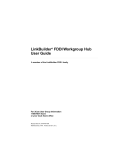
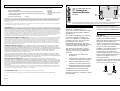
See Figure 1 to locate the MDI/MDIX
jumper and then Figure 2 to ensure
you have the correct selection.
23/12/93
Page 4
Page 1
SQE Test
The PL1 component allows you to
enable or disable the SQE Test. The
SQE Test is used by 802.3 transceivers
to confirm that the transceiver is
functioning correctly. The function
must be disabled for operation when
installed in a Repeater. The function
should be enabled for operation when
connected to a LinkBuilder ECS Local
Bridge Module 3C12050/1.
The Transceiver Module is supplied
with SQE Test disabled.
See Figure 1 to locate the SQE Test
jumper and then Figure 3 to ensure
you have the correct selection.
3
Installation
Only qualified personnel
should install this device.
Observe normal anti-static
precautions! Use an earthed
wrist-band!
A 16-pin header and a 16-way edge
connector are mounted on the
Transceiver Module for connection to a
Module, Stackable Hub or Repeater.
A Twisted Pair cable can be connected
to the RJ45 connector on the front of
the Transceiver Module.
Remove the blanking plate from the
unit in which you are going to install
the Transceiver Module. The relevant
manual will tell you where to find the
plate.
Keep the blanking plate in a safe place
so that it can be replaced if the
Transceiver Module is removed.
!
Page 2
Installing in a Stackable Hub or
Repeater
For FMS Stackables and Repeaters, hold
the mounting panel with the pin header
side of the board down. See Figure 1 to
locate the pin header.
For FMS II Stackables, hold the
mounting panel with the pin header
side of the board up.
Insert the edge connector end of the
Transceiver Module into the rear of the
mother device.
Slide the Transceiver Module in
carefully to engage in the slot and
push it fully home.
Fix the mounting panel of the Transceiver
Module to the back panel using the two
screws from the blanking plate.
Installing in an ECS or MSH Module
Before you install the Transceiver
Module, you must remove the mother
device from the network and all power
sources. Modules must be removed
from the Chassis (you do not need to
power down the chassis first). The
3C18146 Expansion Module must be
separated from its mother module. See
the relevant ‘How to Install and Use...’
manual.
Position the Module on a flat surface
with the 16-way socket facing up. Hold
the Transceiver Module by the
mounting panel and board edge with
the header pins facing down. See
Figure 1 to locate the header pins. Pass
the board of the Transceiver Module
through the cut-out in the front panel.
Align the socket on the Module with
the pins on the Transceiver Module
and push down firmly to connect.
With the 3C18146 Expansion Module,
you align the header and pins and
press gently to engage the pins. Turn
the pair over to rest on the Transceiver
Module and press firmly close to the
header to complete connection.
Fix the mounting panel of the Transceiver
Module to the module using the two
screws from the blanking plate.
Connection
Before proceeding with the installation
of the module, check that the host
equipment is set up to take the
module. See the relevant ‘How to Install
and Use...’ manual.
Re-install the mother device into its
chassis and/or network.
Connect the Transceiver Module to the
TP segment.
4
Operation
Link LED
The Link LED on the front of the
Transceiver Module lights green when
a link is detected. If a link is not
present the LED does not light.
5
Problems
If the Link LED does not light when
the Transceiver Module is installed the
cause may be one of the following:
Both ends of the link are configured as
MDI - change one to MDIX.
Both ends of the link are configured as
MDIX - change one to MDI.
The far end device is not powered up
or may be faulty. Check the device.
The cable linking the devices is broken
or incorrectly wired. Change the cable.
Disclaimer
Information in this document is subject to
change without notice and does not represent a
commitment on the part of 3Com. 3Com
reserves the right to revise or change this
document without obligation of 3Com to notify
any person of the revisions or changes.
Information contained in this document is
believed to be accurate at the time of
publication but no liability whatsoever can be
accepted by 3Com arising out of any use of this
information.
Standards
The 3Com RJ45 Transceiver Module 3C12063
has been designed to comply with the
following standards:
Functional:
PLS & AUI Specification ISO
8802.3 Sect. 7 & 10
Safety:
UL 1950, EN 60950, CSA 22.2 #950
E.M.C.
FCC Part 15 (Level A)
EN55022 (Level A)
VFG 243 (Level B)
IEC 801 (Parts 2-6)
Environment IEC68
Operating Temperature:
0 to 500C
32 to 122 0F
Humidity - 10 to 90% Non Cond.
Radio Frequency Interference Statement
This equipment has been tested with a class A
computing device and has been found to
comply with part 15 of FCC Rules. Operation in
a residential area may cause unacceptable
interference to radio and TV receptions
requiring the operator to take whatever steps
are necessary to correct the interference.
This digital apparatus does not exceed the Class
A limits for radio noise emissions from digital
apparatus as set out in the interference-causing
equipment standard entitled "Digital
Apparatus", ICES-003 of the Department of
Communications.
Cet appareil numérique respecte les limites de
bruits radioélectriques applicables aux appareils
numériques de Classe A prescrites dans la
norme sur le matériel brouilleur : "Appareils
Numériques", NMB-003 édictée par le ministre
des Communications.
3Com and LinkBuilder are registered
trademarks of the 3Com Corporation.
Document No: DUA1206-3AAA01
Revision : 00
Issued: November 1994
© 1994 3Com Technologies Limited
Page 3