1
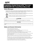
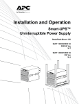
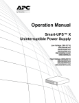
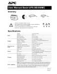
Operation Manual Smart-UPS™ On-Line SRT SRT5KXLI SRT5KRMXLI SRT5KXLT SRT5KRMXLT SRT5KXLT-IEC SRT5KRMXLT-IEC SRT5RMKXLW-HW SRT6KXLI SRT6KRMXLI SRT6KXLT SRT6KRMXLT SRT6KXLT-IEC SRT6KRMXLT-IEC 208/220/230/240 Vac Tower/Rack-Mount 3U/4U Product Description The APC™ by Schneider Electric Smart-UPS™ On-Line SRT is a high performance uninterruptible power supply (UPS). The UPS helps to provide protection for electronic equipment from utility power blackouts, brownouts, sags, surges, small utility power fluctuations and large disturbances. The UPS also provides battery backup power for connected equipment until utility power returns to safe levels or the batteries are completely discharged. This user manual is available on the enclosed Documentation CD and on the APC web site, www.apc.com. General Information Safety Messages Read the instructions carefully to become familiar with the equipment before attempting to install, operate, service or maintain the UPS. The following special messages may appear throughout this manual or on the equipment to warn of potential hazards or to call attention to information that clarifies or simplifies a procedure. The addition of this symbol to a Danger or Warning product safety label indicates that an electrical hazard exists which will result in personal injury if the instructions are not followed. The addition of this symbol to a Warning or Caution product safety label indicates that a hazard exists that can result in injury and product damage if the instructions are not followed. CAUTION CAUTION indicates a potentially hazardous situation which, if not avoided, can result in minor or moderate injury. CAUTION CAUTION addresses practices not related to physical injury including certain environmental hazards, potential damage or loss of data. Smart-UPS On-Line SRT5K/6K Tower/Rack-Mount 3U/4U 1 Safety Information • Adhere to all national and local electrical codes. • All wiring must be performed by a qualified electrician. • Changes and modifications to this unit not expressly approved by APC could void the warranty. • This UPS is intended for indoor use only. • Do not operate this UPS in direct sunlight, in contact with fluids, or where there is excessive dust or humidity. • Be sure the air vents on the UPS are not blocked. Allow adequate space for proper ventilation. • For a UPS with a factory installed power cord, connect the UPS power cable directly to a wall outlet. Do not use surge protectors or extension cords. • The battery typically lasts for two to five years. Environmental factors impact battery life. Elevated ambient temperatures, poor quality utility power, and frequent short duration discharges will shorten battery life. • The equipment is heavy. Always practice safe lifting techniques adequate for the weight of the equipment. • The batteries are heavy. Remove the batteries before installing the UPS and external battery packs (XLBPs), in a rack. • Always install XLBPs at the bottom in rack-mount configurations. The UPS must be installed above the XLBPs. • Always install peripheral equipment above the UPS in rack-mount configurations. • Additional safety information can be found in the Safety Guide supplied with this unit. Deenergizing safety The UPS contains internal batteries and may present a shock hazard even when disconnected from the branch circuit (mains). Before installing or servicing the equipment verify the following: • Mains circuit breaker is in the OFF position • Internal UPS the batteries are removed • XLBP battery modules are disconnected Electrical safety • For models with a hardwired input, the connection to the branch circuit (mains) must be performed by a qualified electrician. • 230 V models only: In order to maintain compliance with the EMC directive for products sold in Europe, output cords attached to the UPS must not exceed 10 meters in length. • The protective earth conductor for the UPS carries the leakage current from the load devices (computer equipment). An insulated ground conductor is to be installed as part of the branch circuit that supplies the UPS. The conductor must have the same size and insulation material as the grounded and ungrounded branch circuit supply conductors. The conductor will typically be green and with or without a yellow stripe. • The UPS input ground conductor must be properly bonded to protective earth at the service panel. If the UPS input power is supplied by a separately derived system, the ground conductor must be properly bonded at the supply transformer or motor generator set. 2 Smart-UPS On-Line SRT5K/6K Tower/Rack-Mount 3U/4U Battery safety • Before installing or replacing the batteries, remove jewelry such as wristwatches and rings. High short circuit current through conductive materials could cause severe burns. • Do not dispose of batteries by burning them. The batteries may explode. • Do not open or mutilate batteries. Released electrolyte is harmful to the skin and eyes, and may be toxic. Hardwire safety • Verify that all branch circuit (mains) and low voltage (control) circuits are deenergized, and locked out before installing cables or making connections, whether in the junction box or to the UPS. • Wiring by a qualified electrician is required. • Check national and local codes before wiring. • Strain relief is required for all hardwiring (not supplied). • All openings that allow access to UPS hardwire terminals must be covered. Failure to do so may result in personal injury or equipment damage. • Select wire size and connectors according to national and local codes. General information • The UPS will recognize as many as 10 external battery packs connected to the UPS. However there is no limit to the number of XLBPs that can be used with the UPS. Note: For each XLBP added, increased recharge time will be required. • The model and serial numbers are located on a small, rear panel label. For some models, an additional label is located on the chassis under the front bezel. • Always recycle used batteries. • Recycle the package materials or save them for reuse. Smart-UPS On-Line SRT5K/6K Tower/Rack-Mount 3U/4U 3 Product Overview Specifications For additional specifications refer to the APC web site, www.apc.com. Environmental Temperature Maximum Elevation Operating 0º to 40º C (32º to 104º F) Storage -15º to 45º C (5º to 113º F) Operating 0 - 3,000 m (0 - 10,000 ft) Storage 0 - 15,000 m (50,000 ft) Humidity 0% to 95% relative humidity, non-condensing Protection Class IP 20 rating Note: Charge the battery modules every six months during storage. Environmental factors impact battery life. Elevated ambient temperatures, high humidity, poor quality mains power, and frequent short duration discharges will shorten battery life. Physical SRT5K model The UPS is heavy. Follow all lifting guidelines. Lifting guidelines >55 kg (>120 lb) Unit weight batteries included, without packaging 54.6 kg (120 lb) Unit weight batteries included, with packaging Rack-Mount models: 63.6 kg (140 lb) Tower models: 67 kg (147.4 lb) Unit dimensions without packaging Height x Width x Depth 130 mm x 432 mm x 719.4 mm 5 in x 17 in x 28.3 in Unit dimensions with packaging Height x Width x Depth 330 mm x 610 mm x 960 mm 13 in x 24 in x 37.8 in The model and serial numbers are on a small label located on the rear panel. SRT6K model The UPS is heavy. Follow all lifting guidelines. Lifting guidelines >55 kg (>120 lb) Unit weight batteries included, without packaging 60 kg (132 lb) Unit weight batteries included, with packaging 67 kg (147.4 lb) Unit dimensions without packaging Height x Width x Depth 174 mm x 432 mm x 719.4 mm 6.9 in x 17 in x 28.3 in Unit dimensions with packaging Height x Width x Depth 370 mm x 610 mm x 960 mm 14.6 in x 24 in x 37.8 in The model and serial numbers are on a small label located on the rear panel. 4 Smart-UPS On-Line SRT5K/6K Tower/Rack-Mount 3U/4U Battery Battery type Replacement battery module Maintenance free, leak proof, sealed, lead acid APCRBC140 This UPS has hot swappable battery modules. Replacement is a safe procedure, isolated from electrical hazards. Refer to the appropriate replacement battery user manual for installation instructions. Contact your dealer or go the APC web site, www.apc.com for information on replacement batteries. Number of battery modules 2 battery modules Voltage for each battery module Total voltage for the UPS Ah rating 96 VDC 192 VDC 5.1 Ah per battery module XLBP cable length 500 mm (19.7 in) Electrical Models Rating SRT5KXLT SRT5KRMXLT SRT5KXLT-IEC 5 kVA/4.25 kW SRT5KRMXLT-IEC SRT5KXLI SRT5KRMXLI 5 kVA/4.5 kW SRT5KRMXLW-HW SRT6KXLT SRT6KRMXLT SRT6KXLT-IEC SRT6KRMXLT-IEC 6 kVA/6 kW SRT6KXLI SRT6KRMXLI Output Output Frequency 50 Hz/60 Hz ± 3 Hz Nominal Output Voltage SRT5KRMXLW-HW: 208V, 220V, 230V, 240V SRT5K/6KXLI, SRT5K/6KRMXLI: 220V, 230V, 240V SRT5K/6KXLT/XLT-IEC, SRT5K/6KRMXLT/RMXLT-IEC: 208V, 240V Input Input Frequency 40 Hz-70 Hz ± 3 Hz Nominal Input Voltage SRT5KRMXLW-HW: 208 V, 220 V, 230 V, 240 V SRT5K/6KXLI, SRT5K/6KRMXLI: 220 V, 230 V, 240 V SRT5K/6KXLT/XLT-IEC, SRT5K/6KRMXLT/RMXLT-IEC: 208 V, 240 V Smart-UPS On-Line SRT5K/6K Tower/Rack-Mount 3U/4U 5 Front panel features Display interface panel UPS battery connectors Battery compartment su0877a Bezel 6 Smart-UPS On-Line SRT5K/6K Tower/Rack-Mount 3U/4U Rear panel features Note: Refer to the table “Key to identify rear panel features” on page 10, that provides a key to the callout numbers for the rear panel graphics depicted in this manual. Output: 50/60 Hz 220/230/240 VAC su0878a GROUP 2 16 AMP MAX GROUP 1 10 AMP MAX SRT5KXLI/SRT5KRMXLI SRT5KXLT/SRT5KRMXLT Output: 50/60 Hz 208//240 VAC GROUP 1 20 AMP MAX su0879a GROUP 2 30 AMP MAX Smart-UPS On-Line SRT5K/6K Tower/Rack-Mount 3U/4U 7 SRT5KXLT-IEC/SRT5KRMXLT-IEC GROUP 1 15 AMP MAX su0880a GROUP 2 20 AMP MAX Output: 50/60 Hz 208/240 VAC su0881a SRT5KRMXLW-HW 8 Smart-UPS On-Line SRT5K/6K Tower/Rack-Mount 3U/4U SRT6KXLI/SRT6KXRMXLI Output: 50/60 Hz 220/230/240 VAC GROUP 2 16 AMP MAX su0882a GROUP 3 16 AMP MAX GROUP 1 10 AMP MAX SRT6KXLT/SRT6KRMXLT GROUP 1 20 AMP MAX su0883a GROUP 2 30 AMP MAX GROUP 3 30 AMP MAX Output: 50/60 Hz 208/240 VAC SRT6KXLT-IEC/SRT6kRMXLT-IEC Output: 50/60 Hz 208/240 VAC GROUP 3 20 AMP MAX su0884a GROUP 2 20 AMP MAX GROUP 1 15 AMP MAX Smart-UPS On-Line SRT5K/6K Tower/Rack-Mount 3U/4U 9 Key to identify rear panel features SmartSlot The SmartSlot can be used to connect optional management accessories. External battery power and communication connector Use the external battery cable on the XLBP to connect the UPS and XLBP. XLBPs provide extended runtime during power outages. The UPS will automatically recognize up to 10 external battery packs. Chassis ground screws The UPS and XLBPs have ground screws for connecting the ground leads. Prior to connecting a ground lead, disconnect the UPS from mains power. Hardwire output box SRT5KRMXLW-HW, SRT6KXLI, SRT6KRMXLI, SRT6KXLT, SRT6KRMXLT, SRT6KXLT-IEC, SRT6KRMXLT-IEC models are equipped with a hardwire output box. Refer to “Wiring Specifications” on page 11 for hardwire specifications. Remove the knockouts. Snap-In strain reliefs are recommended (not supplied). EPO terminal The Emergency Power Off (EPO) terminal allows the user to connect the UPS to a central EPO system. Serial Com The Serial Com port is used to communicate with the UPS. Use only interface kits supplied or approved by APC by Schneider Electric. Any other serial interface cable will be incompatible with the UPS connector. USB port The USB port is used to connect either a server for native operating system communications, or for software to communicate with the UPS. Note: Serial and USB communication should not be used simultaneously. Use either the Serial Com or the USB port. Universal I/O port Use to connect: • Temperature sensor AP9335T (supplied) • Temperature/humidity sensor AP9335TH (not supplied) • Relay input/output connector AP9810 (not supplied), supports two input contacts and one output relay Console port Use the Console port to configure the network management features. Network port Use the Network port to connect the UPS to the network. Reset button Use the Reset button to restart the Network Management Interface. Note: A restart of the Network Management Interface does not affect UPS operation. AC input power cable or hardwire input box • SRT5KXLT, SRT5KRMXLT, SRT5KXLT-IEC, SRT5KRMXLT-IEC models have factory installed input power cables. • All other models are equipped with a hardwire input box. Refer to “Wiring Specifications” on page 11. Remove the knockouts. Snap-In strain reliefs are recommended (not supplied). Controllable outlet group 1 Connect electronic devices to these outlets. Controllable outlet group 2 Connect electronic devices to these outlets. Controllable outlet group 3 Connect electronic devices to these outlets. Circuit breaker In the event an overload condition occurs, disconnect nonessential equipment. Then reset the circuit breaker. 10 Smart-UPS On-Line SRT5K/6K Tower/Rack-Mount 3U/4U Wiring Specifications CAUTION DAMAGE TO EQUIPMENT OR PERSONNEL • Adhere to all national and local electrical codes. • Wiring should be performed by a qualified electrician. • Strain reliefs are not provided with this unit. Snap-In strain reliefs are recommended. Refer to the Installation Guide for knockout panel sizes. • The UPS must be wired into a branch circuit, equipped with a circuit breaker rated as specified in the tables below. • Actual wire size must comply with required amp capacity and national and local electrical codes. • Recommended input terminal screw torque: 16 lbf-in (2 Nm). Failure to follow these instructions can result in equipment damage and minor or moderate injury SRT5K/6KXLT, SRT5K/6KXLT-IEC models Input connections Wire to L1, L2, Output connections Wire to L1, L2, System Wiring SRT5KXLT SRT5KRMXLT SRT5KXLT-IEC SRT5KRMXLT-IEC SRT6KXLT SRT6KRMXLT SRT6KXLT-IEC SRT6KRMXLT-IEC Input Output Input Output Voltage Current full load, nominal External input circuit breaker, (typical) Wire size, typical 208/240 Vac 24 A 30 A/2-pole Not applicable 50 A/2-pole 6 AWG 33 A 208/240 Vac 29 A SRT5KXLI/SRT6KXLI models Input connections Single phase: Wire to L, N, Output connections Wire to L, N System SRT5KXLI SRT5KRMXLI SRT6KXLI SRT6KRMXLI Wiring Input Output Input Output Voltage Current full load, nominal External input circuit breaker, (typical) Wire size, typical 220/230/240 Vac 24 A 40 A/2-pole 10 mm2 50 A/2-pole 16 mm2 220/230/240 Vac 32 A 28 A Smart-UPS On-Line SRT5K/6K Tower/Rack-Mount 3U/4U 11 SRT5KRMXLW-HW Input connections Single phase: Wire to L, L2/N, Output connections Wire to L1, L2/N System SRT5KRMXLW-HW Wiring Voltage Current full load, nominal Input 208/220/ 230/240 Vac 26 A Output 12 External input circuit breaker, (typical) 40 A/2-pole 24 A Smart-UPS On-Line SRT5K/6K Tower/Rack-Mount 3U/4U Wire size, typical 10 mm2 (8 AWG) Connect Equipment CAUTION DAMAGE TO EQUIPMENT OR PERSONNEL • Disconnect the mains input circuit breaker before installing or servicing the UPS or connected equipment. • Disconnect internal and external batteries before installing or servicing the UPS or connected equipment. • The UPS contains internal and external batteries that may present a shock hazard even when disconnected from the mains. • UPS AC hardwired and pluggable outlets may be energized by remote or automatic control at any time. • Disconnect equipment from the UPS before servicing any equipment. Failure to follow these instructions can result in equipment damage and minor or moderate injury. Note: The UPS batteries will charge to 90% capacity in the first three hours of normal operation. Do not expect full battery runtime capability during this initial charge period. 1. Connect equipment to the outlets on the rear panel of the UPS. Refer to “Controllable Outlet Groups” on page 21. 2. Connect the UPS to the building utility power. Turn the UPS On/Off The first time the UPS is turned on the Setup Wizard screen will run. Follow the prompts to configure UPS settings. Refer to “Configuration” on page 17. To turn on the UPS and all connected equipment, press the Power ON/OFF button on the display panel. Follow the prompts to either turn the UPS on immediately or after a delay, then press OK. NOTE: When there is no input power and the UPS is off, the cold start feature can be used to turn on the UPS and connected equipment using battery power. To perform a cold start press the Power ON/OFF button. The display panel will illuminate and the Power ON/OFF button will illuminate red. To turn on the output power press the Power ON/OFF button again. Select the prompt Turn ON with NO AC and press OK. To turn output power off, press the Power ON/OFF button. Follow the prompts to either turn the UPS off immediately or after a delay, then press OK. NOTE: Once the AC power has been turned off the UPS will continue operating on battery power for a short period of time. To remove power completely press the Power ON/OFF button. Follow the prompt to select Internal Power Off, then press OK. Smart-UPS On-Line SRT5K/6K Tower/Rack-Mount 3U/4U 13 UPS Display Interface POWER ON/OFF button Button illumination indications: -No illumination, the UPS and the output power are off -White illumination, the UPS and the output power are on -Red illumination, the UPS is on and the output power is off Load icon Disable/mute audible alarm icon LOA D Output 230.0 v On-Line 1 2 UPS status information Operation mode icons ESCAPE button OK button su0870b UP/DOWN buttons Controllable outlet group status icons Battery status icons . The icons on the LCD display interface screen may vary depending on the installed firmware version. LOAD Load icon: The approximate load capacity percentage is indicated by the number of load bar sections illuminated. Each bar represents 16% of the load capacity. Mute icon: Indicates the audible alarm is disabled/mute. UPS Status Information The status information field provides key information on the status of the UPS. The Standard menu will allow the user to select one of the following screens. The Advanced menu will scroll through the following five screens. Input Voltage Output Voltage Output Frequency Load Runtime In the case of a UPS event, status updates will be displayed defining the event or condition that has occurred. The display screen illuminates amber to indicate a Warning and red to indicate an Alert depending on the severity of the event or condition. 14 Smart-UPS On-Line SRT5K/6K Tower/Rack-Mount 3U/4U Operation Mode Icons On-Line mode: The UPS is supplying conditioned mains power to connected equipment. Bypass mode: The UPS is in Bypass mode and the connected equipment will receive mains power as long as the input voltage and frequency are within the configured limits. Green mode: When in Green mode mains power is sent directly to the load. In the event of a mains power outage, there will be an interruption in power to the load of up to 8 ms while the UPS switches to On-Line or Battery mode. When enabling Green mode consideration should be given to devices that may be sensitive to power fluctuations. Battery mode: The UPS is supplying battery power to connected equipment. Controllable Outlet Group Icons Controllable Outlet Group Power Available: The number next to the icon identifies the specific outlet groups that have available power. Controllable Outlet Group Power Not Available: The number next to the icon identifies specific outlet groups that do not have available power. Battery Status Icons Battery Charge Status: Indicates the battery charge status. Battery Charge In Progress: Indicates the battery is charging. UPS Display Interface operation Use the UP/DOWN buttons to scroll through the options. Press the OK button to accept the selected option. Press the ESC button to return to the previous menu. Menu overview The UPS Display Interface has Standard and Advanced menu screens. The preference for Standard or Advanced menu selections is made during initial installation and can be changed at any time through the Configuration menu. The Standard menus include the most commonly used options. The Advanced menus provide additional options. Note: Actual menu screens may differ by model and firmware version. Smart-UPS On-Line SRT5K/6K Tower/Rack-Mount 3U/4U 15 LCD display interface angle adjustment The angle of the LCD display interface can be adjusted for ease in viewing the displayed messages. 1. Remove the front bezel. 2. Locate the button on the bottom of the display interface panel. 3. Press the button and slide the bottom of the LCD display interface screen out. An audible click will be heard when the screen reaches the maximum angle. su 16 09 26 a Smart-UPS On-Line SRT5K/6K Tower/Rack-Mount 3U/4U Configuration Menus Overview Main Menu Status Control Configuration Test And Diagnostics Log About Status Menu UPS Battery Accessory*** Control Menu** UPS Bypass Outlet Group 1* Outlet Group 2* Outlet Group 3* Clear Alarms UPS** Efficiency Output Power, VA, Watts, % Output Voltage, Current, Frequency Energy Usage Battery State Of Charge, Runtime Input Voltage, Frequency Bypass Voltage, Frequency Self Test Runtime Test Config Menu UPS Battery Outlets* Communication Display UPS** Turn On / Off / Reboot UPS Bypass** Go into Bypass Go out of Bypass Outlet Group Turn On / Off / Reboot* Battery Battery Status Information Accessory Network Management Interface Information* Test and Diagnostics Menu Self Test Runtime Test Alarm Test UPS Green mode Enable / Disable Output Voltage / Frequency Settings Bypass Settings Battery Settings Self Test Schedule Default Setting Reset Energy Meter* Battery Install Date Replace Notification Replace Battery Alarm Outlets Main Outlet Outlet Group 1 Outlet Group 2 Outlet Group 3 Communication Network IP Address / Boot Mode MODBUS Address* Menus are subject to change depending on the installed firmware version * Available on the Advanced Menu Screens ** Options displayed will vary based on UPS state. ***Options displayed will vary based on connected accessories. Display Language Beeper Volume LCD Backlight Menu type - Standard / Advanced Log Event Log About Menu UPS Battery Accessory UPS Part Number Serial Number Manufacture Date Firmware Version Date and Time Battery Part Number Install And Replace Date Firmware Version* Accessory MAC Address IP Address Firmware Version Configuration UPS Settings There are four ways to select UPS configuration options. 1. The first time the UPS is turned on the Setup Wizard screen will open. On each menu screen select the desired settings. Press OK after each UPS setting is selected. Note: The UPS will not turn on until all of the settings have been configured. 2. Main Menu/Configuration/UPS/Load Default. This screen allows the user to reset the UPS to factory default settings. Press OK after the UPS setting is selected. Refer to “Configuration” on page 17 and “Menu overview” on page 17. 3. Configure settings using an external interface, such as the Network Management Web interface. Startup configuration Function Description Select the language required for the display interface. Language Language options will vary by model and firmware version. Francais Italiano Setup Wizard Options: • English • Francais • Italiano • Deutch • Espanol • Portugues • Russian Select the output voltage. Voltage AC Setting 220 VAC 240 VAC Setup Wizard Options: • 208 Vac • 220 Vac • 230 Vac • 240 Vac The Standard menu options are the most commonly used options. Menu Type The Advanced menu options will be used by IT professionals who need detailed configuration and reporting information. Advanced Setup Wizard Smart-UPS On-Line SRT5K/6K Tower/Rack-Mount 3U/4U 17 General settings Configure these settings at any time, using the display interface, or the Network Management Web Interface. Parameters Config Menu UPS Green Mode Default Value Disabled Disable Description Disable or enable Green mode operation Enable User Choice AC Setting 230 V, 220 V, 240 V, 208 V Set the output voltage for the UPS. This setting can only be changed when the UPS output is off. These settings may vary depending on the UPS model. Output Lower Acceptable Voltage 184 V for 208 V output 198 V for 220 V output 207 V for 230 V output 216 V for 240 V output 208 V - 169 to 184 V 220 V - 186 to 198 V 230 V - 195 to 207 V 240 V - 204 to 216 V Output Upper Acceptable Voltage 220 V for 208 V output 242 V for 220 V output 253 V for 230 V output 264 V for 240 V output 208 V - 220 to 235 V 220 V - 242 to 253 V 230 V - 253 to 265 V 240V - 264 to 270 V If the output voltage goes outside the acceptable range the UPS will switch from Green mode to OnLine mode or to Battery mode. Auto 50/60 ± 3Hz Auto 50/60 ± 3 Hz 50 ± 0.1 Hz 50 ± 3.0 Hz 60 ± 0.1 Hz 60 ± 3.0 Hz Set the output frequency for the UPS. Output Frequency Slew Rate 1 Hz/Sec 0.5 Hz/Sec 1 Hz/Sec 2 Hz/Sec 4 Hz/Sec Select the rate of change for output frequency in Hertz per second. Bypass Lower Acceptable Voltage 160 V 208 V - 160 to 184 V 220 V - 160 to 198 V 230 V - 160 to 207 V 240V - 160 to 216 V Bypass Upper Acceptable Voltage 250 V for 208 V output 255 V for 220 V output 265 V for 230 V output 270 V for 240 V output 208 V - 220 to 250 V 220 V - 242 to 264 V 230 V - 253 to 270 V 240 V - 264 to 270 V Allow Wider Frequency Allow Wider Frequency The setting Allow Wider Frequency, enables Bypass mode operation for an input frequency Follow Frequency range of Setting 47-63 Hertz. 150 seconds 0 to 1800 seconds The UPS will emit an audible alarm when the remaining runtime has reached this threshold. Startup + every 14 days since last test Never Startup Startup + 14 days Startup + 7 days This is the interval at which the UPS will execute a Self Test. No Yes/No Allows the user to restore the UPS factory default settings. No Yes/No The Energy Meter stores information on UPS output energy usage. Output Frequency Bypass Mode Low Runtime Warning Self Test Schedule Default Setting Reset Energy Meter 18 Options If the UPS input voltage is between the lower acceptable voltage and the higher acceptable voltage, the UPS will operate in Green mode when enabled. If the UPS input voltage is between the lower acceptable voltage and the higher acceptable voltage, the UPS can enter Bypass mode when enabled. The Reset feature allows the user to reset the Energy Meter to 0 kWh. Smart-UPS On-Line SRT5K/6K Tower/Rack-Mount 3U/4U Parameters Config Install Date Menu Battery Default Value Options Description Battery Installation Date Month-Year Enter the installation date of the RBCs. 180 days 0-360 days To set the Near End of Life alarm, select the number of days before the estimated battery end of life. When this date is reached the UPS will emit an alarm and a message will appear on the display interface screen. Replacement Notification Time Example: Using the default value, the Near End of Life alarm will occur 180 days before the estimated end of life date. Replacement Battery Alarm Time Config Menu Display Language 14 days 0-180 days The Near End of Life alarm can be muted. Enter the number of days between the time a Near End of Life alarm is acknowledged and the next Near End of Life alarm occurs. English English Francais Italiano Deutch Espanol Portugues Russian Select the language required for the display interface. Disable When audible alarms are disabled, the UPS will never emit an audible alarm. Loud Enable Beeper Volume • Soft • Medium • Loud Auto Dim LCD Back Light LCD Setting Menu Type Always On Auto Dim Auto Off Language options will vary by model and firmware version. Select the volume level for alarms when Enable is selected. To conserve energy, the LCD back light illumination dims or turns off when no events are active. Full display interface illumination returns when the UPS changes status as a result of an event or when any button on the display interface is pressed. Optimal Values Color Brightness Contrast Adjust the brightness and contrast individually for each LCD back light color. User Choice Standard Advanced The Standard menus include the most commonly used options. The Advanced menu options include all parameters. Smart-UPS On-Line SRT5K/6K Tower/Rack-Mount 3U/4U 19 Parameters Default Value Description 0 seconds 0-1800 seconds Select the amount of time the controllable outlet groups will wait between receiving the command to turn on and actual startup. Power Off Delay 90 seconds 0-32767 seconds Select the amount of time the controllable outlet groups will wait between receiving the command to shutdown and actual shutdown. Reboot Duration 8 seconds 4-300 seconds Select the amount of time the controllable outlet groups will remain off before the UPS will restart. Minimum Return Runtime 0 seconds 0-32767 seconds Select the amount of battery runtime that must be available before the controllable outlet groups will turn on using battery power, after a shutdown. Disable Disable Enable To conserve battery power the UPS can disconnect power from controllable outlet groups not in use. Config Power On Menu Delay Outlets Loadshed On Battery To configure the disconnect delay time for this feature use the Loadshed Time On Battery setting. Loadshed Time 5 seconds On Battery 5-32767 seconds Select the amount of time the controllable outlet groups will be allowed to function on battery power before shutdown. Loadshed On Runtime Disable Disable Enable To conserve battery power the UPS can disconnect power from controllable outlet groups when the Loadshed Runtime threshold is reached. Loadshed Runtime 0 seconds 0-3600 seconds When the selected runtime threshold is reached the UPS will shutdown the controllable outlet groups. Disable Disable Enable To conserve energy in the event of an overload condition greater than 105% output, the controllable outlet groups will immediately turn off. The controllable outlet groups will only turn on again with a manual restart command once the overload condition has been corrected. Loadshed Overload Config IP Address Menu Mode Network Manage IP Address 20 Options Manual, DHCP, BOOTP Refer to the Network Management Utility CD. Program IP, Subnet, Gateway Smart-UPS On-Line SRT5K/6K Tower/Rack-Mount 3U/4U Controllable Outlet Groups Controllable Outlet Groups provide battery backup power to connected equipment. Overview The controllable outlet groups can be configured using the Advanced menu options. Refer to “General settings” on page 18. The controllable outlet groups can be configured to independently turn off, turn on, shutdown, switch to Sleep mode, and reboot connected equipment. • Turn Off: Disconnect output power to connected equipment either immediately using the Turn Off Immediately feature or after a configured delay using the Turn Off With Delay feature. NOTE: Controllable outlet groups can be turned on only using the Turn On feature. • Turn On: Connect output power to connected equipment either immediately using the Turn On Immediately feature or after a configured delay using the Turn On With Delay feature. • Shutdown: Disconnects the power to connected equipment either immediately or after a configured delay. Equipment reconnects after a configured delay when mains power becomes available and other configured conditions are met. Each controllable outlet group can be configured separately to allow power sequencing for equipment connected to any controllable outlet group. • Reboot: Disconnect the power to connected equipment either immediately or after a configured delay. Reconnect equipment after a configured delay when either mains or battery power becomes available and other configured conditions are met. Each controllable outlet group can be configured separately to allow power sequencing for loads connected to any controllable outlet group. • Sleep: This mode is a reboot with an extended duration where a outlet(s) remain turned off. Disconnect the power to connected equipment either immediately or after a configured delay. Reconnect equipment after a configured delay when either mains or battery power becomes available and other configured conditions are met. Each controllable outlet group can be configured separately to allow power sequencing for equipment connected to any controllable outlet group. To configure Sleep mode use an external interface, such as the Network Management Web interface. • Automatically turn off or shutdown when certain conditions occur, based on user configurations set using the Config Menu Outlets menus. Refer to “Configuration” on page 17 Connect controllable outlet groups • Connect critical equipment to one controllable outlet group. • Connect peripheral equipment to the other controllable outlet groups. – To conserve battery runtime during a power outage, nonessential equipment can be configured to shut down. Use Loadshed Time on Battery Enable/Disable and Loadshed Time on Battery Setting defined in the General Settings section. Refer to “General settings” on page 18. – If equipment has dependent peripherals that must restart or shut down in a specific sequence, such as an ethernet switch that must restart before a connected server can be restarted, connect the devices to different outlet groups. Each controllable outlet group can be configured independently of the other groups. • Use the Configuration menus to configure how the controllable outlet groups will react in the event of a power outage. Smart-UPS On-Line SRT5K/6K Tower/Rack-Mount 3U/4U 21 Emergency Power Off Overview The Emergency Power Off (EPO) option is a feature that will immediately disconnect all connected equipment from mains power. The UPS will immediately shut down and will not switch to battery power. Connect each UPS to the EPO switch. In configurations where multiple units are connected in parallel, each UPS must be connected to the EPO switch. The UPS must be restarted for power to return to connected equipment. Press the ON/OFF button on the front panel of the UPS. CAUTION RISK OF DAMAGE TO EQUIPMENT OR PERSONNEL • Adhere to all national and local electrical codes. • Wiring must be performed by a qualified electrician. • Always connect the UPS to a grounded outlet. Failure to follow these instructions can result in equipment damage and minor or moderate injury. Normally open contacts 1. If the EPO switch or relay contacts are normally open, insert the wires from the switch or contacts at pins 1 and 2 of the EPO terminal block. Use 16-28 AWG wire. 2. Secure the wires by tightening the screws. If the contacts are closed, the UPS will turn OFF and power will be removed from the load. Normally closed contacts 1. If the EPO switch or relay contacts are normally closed, insert the wires from the switch or contacts at pins 2 and 3 of the EPO terminal block. Use 16-28 AWG wire. 2. Insert a wire jumper between pins 1 and 2. Secure the wires by tightening the three screws at positions 1, 2, and 3. If the contacts are opened, the UPS will turn OFF and power will be removed from the load. Note: Pin 1 is the power source for the EPO circuit, it provides a few milliampere of 24 V power. If the normally closed (NC) EPO configuration is used, the EPO switch or relay should be rated for “dry” circuit applications, the rating should be for low voltage and low current applications. This normally implies the contacts are gold plated. The EPO interface is a Safety Extra Low Voltage (SELV) circuit. Connect the EPO interface only to other SELV circuits. The EPO interface monitors circuits that have no determined voltage potential. SELV circuits are controlled by a switch or relay properly isolated from mains power. To avoid damage to the UPS, do not connect the EPO interface to any circuit other than a SELV circuit. Use one of the following cable types to connect the UPS to the EPO switch. • CL2: Class 2 cable for general use. • CL2P: Plenum cable for use in ducts, plenums, and other spaces used for environmental air. • CL2R: Riser cable for use in a vertical run in a floor to floor shaft. • CLEX: Limited use cable for use in dwellings and for use in raceways. • Installation in Canada: Use only CSA certified, type ELC, (extra low voltage control cable). • Installation in countries other than Canada and the USA: Use standard low voltage cable in accordance with national and local regulations. 22 Smart-UPS On-Line SRT5K/6K Tower/Rack-Mount 3U/4U Network Management Interface Introduction The UPS has a network port and console port that can be used to access the Network Management Interface. The Network Management Interface is very similar to an AP9630 Network Management Card (NMC) that is integrated into a UPS with one universal input/output port. The Network Management Interface and the AP9630 NMC have the same firmware, operation modes and interaction with other APC products such as PowerChute Network Shutdown. Refer to the Network Management Card utility CD supplied with this product. Features The Network Management Interface allows the UPS to function as a Web based, IPv6 ready product. The Network Management Interface can manage the UPS using multiple open standards such as: Hypertext Transfer Protocol (HTTP) Secure SHell (SSH) Simple Network Management Protocol versions 1 and 3 (SNMPv1, SNMPv3) Hypertext Transfer Protocol over Secure Sockets layer (HTTPS) File Transfer Protocol (FTP) Secure Copy (SCP) Telnet Syslog RADIUS The Network Management Interface: • Provides UPS control and Self Test scheduling features. • Provides data and event logs. • Enables you to set up notifications through event logging, e-mail, and SNMP traps. • Provides support for PowerChute Network Shutdown. • Supports using a Dynamic Host Configuration Protocol (DHCP) or BOOTstrap Protocol (BOOTP) server to provide the network (TCP/IP) values. • Supports use of Remote Monitoring Service (RMS). • Provides the ability to export a user configuration (.ini) file from a configured UPS, to one or more unconfigured UPS without conversion to a binary file. • Provides a selection of security protocols for authentication and encryption. • Communicates with StruxureWare Central and InfraStruxure Manager. • Supports one universal input/output port for connection to a: – Temperature probe, AP9335T (supplied) – Temperature/humidity sensor, AP335TH (optional) – Relay input/output connector that supports two input contacts and one output relay, AP9810 Dry Contact I/O Accessory (optional) Smart-UPS On-Line SRT5K/6K Tower/Rack-Mount 3U/4U 23 Related Documents The Network Management Card Utility CD contains the following documentation: • UPS Network Management Card 2 User’s Guide • Network Management Card Upgrade Utilities • Security Handbook • PowerNet Management Information Base (MIB) Reference Guide IP Address Configuration The default TCP/IP configuration setting DHCP, assumes that a properly configured DHCP server is available to provide TCP/IP settings to the Network Management Interface. If the Network Management Interface obtains an IPv4 address from a DHCP server, use the display interface menus About/ Interface, to see the address. To setup a static IPv4 address use the display interface Config menu. Set the IP address Subnet Mask and Gateway from the Config menu. See the User’s Guide on the Network Management Card Utility CD for user information about the Network Management Interface and for setup instructions. 24 Smart-UPS On-Line SRT5K/6K Tower/Rack-Mount 3U/4U Smart Battery Management Definitions • Battery Module: A string of battery cells arranged to produce a battery assembly with a connector. • Replaceable Battery Cartridge (RBC): An APC battery cartridge consisting of two battery modules. Replacement RBCs can be ordered from the APC web site, www.apc.com. • Smart External Battery Pack (XLBP): An enclosure that contains RBC(s) and battery management electronics. • User Interface (UI): Any interface by which a user can interact with the system. This may include a UPS display interface, a network management interface or PowerChute™ Network Shutdown software. NOTE: Do not use a battery that is not APC approved. The system will not detect the presence of a non APC approved battery and may adversely affect the operation of the system. Use of a non APC approved battery will void the manufacturer warranty. Features Smart Battery Management provides the following features: • Monitors and informs the user of the health of each RBC. • Monitors and shows on the UPS Display Interface screen, the date for the end of useful life for each RBC. • The UPS emits an alarm and shows a message on the UPS Display Interface screen to indicate the estimated battery end of life. On the UPS Display Interface screen the user can set the number of days before the alarm is heard and the message appears on the UPS Display Interface screen. • Automatically detects the addition or removal of XLBPs and RBCs. • Monitors the internal temperature of each XLBP and automatically adjusts the battery charging. Maintenance • RBC maintenance: The APC RBC uses sealed lead acid battery cells and does not require maintenance. • Runtime Test (Calibration): This should be performed anytime the steady state load is changed significantly, for example a new server is added to or removed from the UPS load. • Battery health monitoring: The battery energy output and voltage are monitored to assess the health of the installed batteries when the UPS is operating on battery. Battery health monitoring is done during a UPS Self Test, a Runtime Calibration Test, and when the UPS is operating on battery power. The UPS can be configured to perform periodic, automatic Self Tests. End of useful life • Near end of life notification: A warning message will appear on the UPS display interface screen when each RBC is approaching the end of its useful life. For configuration details refer to Replacement Notification Time and Replacement Battery Alarm Time. The estimated replacement date for each RBC is available through the UI. • Needs replacement notification: The UPS display interface screen shows when RBC replacement is required. The RBC must be replaced as soon as possible. When an RBC requires replacement, the UPS display interface may recommend that additional RBCs be replaced if they will soon reach the end of their useful life. CAUTION: Continued operation after end of useful life notification may cause damage to the batteries. • Recycling: Remove the RBC from the XLBP. Recycle the RBC. Do not disassemble an RBC. Smart-UPS On-Line SRT5K/6K Tower/Rack-Mount 3U/4U 25 Replace the RBCs in a UPS An RBC should only be disconnected or removed from the UPS temporarily as part of the battery replacement procedure. • Disconnect all connected battery modules in the UPS. Slide the RBCs out of the UPS. • Slide the new RBCs into the UPS and connect the battery modules to the UPS. • Securely connect each battery module. Press the battery connector into the UPS until it is firmly connected. A battery that is not fully connected will cause erratic UPS operation, abnormal error messages and connected equipment may not receive battery power during power outages. • After installing the RBC, the UPS display interface may prompt the user to verify the status of the replaced battery modules. If the battery module is new, respond YES. If the battery module is not new, respond NO. Recommended actions after installing new RBCs • Verify that the UPS is connected to input power and the output power is turned on. Refer to the Operation section in this manual for instructions. • Verify that the UPS load is greater than 400 watts. This will appear on the UPS display interface screen. • Perform a UPS Self Test. • Verify on the UPS display interface that the installation dates for the replaced RBCs are set to the current date. The installation dates can be changed manually on the UPS display interface. If all RBCs have been replaced at the same time, all installation dates can be changed simultaneously. For configuration details refer to Battery Install Date on page 19 of this manual. • Allow the system to charge for 24 hours to ensure full runtime capability. XLBP installation and replacement Refer to the External Battery Pack Installation Guide for installation and replacement instructions. 26 Smart-UPS On-Line SRT5K/6K Tower/Rack-Mount 3U/4U Troubleshooting Use the table below to solve minor installation and operation problems. Refer to the APC web site, www.apc.com for assistance with complex UPS problems. The UPS features firmware that can be upgraded. Go to the APC web site, www.apc.com/Support, or contact your local Customer Care Center for more information. Problem and Possible Cause Solution UPS will not turn on or there is no output The UPS is not connected to mains power. Be sure the power cable is securely connected to the UPS and to the mains power supply. The UPS display interface screen shows very low or no mains power. Check the mains power supply to verify acceptable power quality. There is an internal UPS alert or warning. The UPS Display Interface screen will show a message to identify the alert or warning and corrective action. UPS emits an audible alarm Normal UPS operation when running on battery power. The UPS is operating on battery power. Refer to the status of the UPS as shown on the UPS Display Interface screen. Press any key to mute all alarms. The UPS emits an audible alarm and has An Alarm or Warning condition exists. a red or amber back light on the UPS Refer to the display interface screen for information. Display Interface screen. UPS does not provide expected backup time The UPS batteries are weak due to a recent power outage or they are near the end of service life. Charge the batteries. Batteries require recharging after extended outages and wear out faster when put into service often or when operated at elevated temperatures. If the batteries are near the end of service life, consider replacing the batteries even if the Replace Battery message is not displayed. The UPS is experiencing an overload condition. The connected equipment exceeds the specified maximum load. Refer to the APC web site, www.apc.com for product specifications. The UPS will emit a sustained audible alarm until the overload condition is corrected. Disconnect nonessential equipment from the UPS to correct the overload condition. Smart-UPS On-Line SRT5K/6K Tower/Rack-Mount 3U/4U 27 Problem and Possible Cause Solution UPS operates on battery power while connected to mains power The input circuit breaker has tripped. Reduce the load on the UPS. Disconnect nonessential equipment and reset the circuit breaker. Check the circuit breaker rating for the connected equipment. There is very high, very low, or distorted Navigate to the UPS Display Interface screen that shows input voltage. Verify that input line voltage. the input voltage is within specified operating limits. If no input voltage is indicated on the UPS Display Interface screen, contact Customer Support through the APC web site, www.apc.com. The UPS Display Interface screen shows The UPS has been configured to operate for a specified period of runtime. The the message Waiting for Minimum setting can be changed through the Config/UPS menus. Runtime. UPS Display Interface Status screen shows Overload and the UPS emits a sustained audible alarm The UPS is experiencing an overload condition. The connected equipment exceeds the maximum load rating for the UPS. The UPS will emit a sustained audible alarm until the overload condition is corrected. Disconnect nonessential equipment from the UPS to correct the overload condition. UPS Display Interface Status screen shows UPS is operating in Bypass mode The UPS received a command to operate No action is required. in Bypass mode The UPS has automatically switched to Bypass mode due to an internal UPS alert or warning. The UPS Display Interface screen will show a message to identify the alert or warning and corrective action. UPS Display Interface is red or amber and shows an alert or warning message The UPS emits a sustained audible alarm The UPS has detected a problem during normal operation. Follow the instructions on the UPS Display Interface screen. Press any key to mute all alarms. The UPS Display Interface screen shows Be sure the battery cables are securely connected. the message Disconnected Battery. Perform a UPS Self Test to be sure the UPS detects all connected batteries. To perform a UPS Self Test use the UPS Display Interface menu option Test and Diagnostics. The UPS Display Interface screen shows Allow the battery to recharge for 24 hours. the message Replace Battery. To perform a Runtime test use the UPS Display Interface menu option Test and Diagnostics. If the problem persists, replace all of the batteries. 28 Smart-UPS On-Line SRT5K/6K Tower/Rack-Mount 3U/4U Problem and Possible Cause Solution The UPS display turns red or amber, displays an alert message, and emits a sustained audible alarm Red illumination indicates a UPS alarm that requires immediate attention Amber illumination indicates a UPS alarm that requires attention There is an internal UPS alert or warning. Do not attempt to use the UPS. Turn the UPS off and have it serviced immediately. 1/1 Power Sys Error - 00100 Contact Customer Support Output Off 1 2 3 The UPS is experiencing an overload condition. Reduce the load on the UPS. Disconnect nonessential equipment. 1/1 Output Overload Bypass 1 2 3 The Replace Battery alert is displayed The battery has a weak charge. Allow the battery to recharge for at least four hours. Then, perform a UPS Self Test. If the problem persists after recharging, replace the battery. The replacement battery is not properly connected. Be sure the battery cable is securely connected. UPS reports; Battery Sys Error 0800 or Needs Firmware Update UPS reports; Battery Sys Error 0800 or Needs Firmware Update The UPS system firmware must be updated to correct this problem. To update the UPS system firmware go to www.apc.com/support. Select Search the Knowledge Base and search for FA164737. Follow the instructions to upgrade the firmware. Smart-UPS On-Line SRT5K/6K Tower/Rack-Mount 3U/4U 29 Transport 1. Shut down and disconnect all connected equipment. 2. Disconnect the unit from mains power. 3. Disconnect all internal and external batteries (if applicable). 4. Follow the shipping instructions outlined in the Service section of this manual. Service If the unit requires service, do not return it to the dealer. Follow these steps: 1. Review the Troubleshooting section of the manual to eliminate common problems. 2. If the problem persists, contact APC Customer Support through the APC web site, www.apc.com. a. Note the model number and serial number and the date of purchase. The model and serial numbers are located on the rear panel of the unit and are available through the LCD display on select models. b. Call APC Support and a technician will attempt to solve the problem over the phone. If this is not possible, the technician will issue a Returned Material Authorization Number (RMA#). c. If the unit is under warranty, the repairs are free. d. Service procedures and returns may vary internationally. Refer to the APC web site for country specific instructions. 3. Pack the unit properly to avoid damage in transit. Never use foam beads for packaging. Damage sustained in transit is not covered under warranty. a. Note: When shipping within the United States, or to the United States always DISCONNECT ONE UPS BATTERY before shipping in compliance with U.S. Department of Transportation (DOT) and IATA regulations. The internal batteries may remain in the UPS. b. Batteries may remain connected in the XBP during shipment. Not all units utilize XLBPs. 4. Write the RMA# provided by Customer Support on the outside of the package. 5. Return the unit by insured, prepaid carrier to the address provided by Customer Support. 30 Smart-UPS On-Line SRT5K/6K Tower/Rack-Mount 3U/4U Limited Factory Warranty Schneider Electric IT Corporation (SEIT), warrants its products to be free from defects in materials and workmanship for a period of three (3) years excluding the batteries, which are warranted for two (2) years from the date of purchase. The SEIT obligation under this warranty is limited to repairing or replacing, at its own sole option, any such defective products. Repair or replacement of a defective product or part thereof does not extend the original warranty period. This warranty applies only to the original purchaser who must have properly registered the product within 10 days of purchase. Products may be registered online at warranty.apc.com. SEIT shall not be liable under the warranty if its testing and examination disclose that the alleged defect in the product does not exist or was caused by end user or any third person misuse, negligence, improper installation, testing, operation or use of the product contrary to SEIT recommendations of specifications. Further, SEIT shall not be liable for defects resulting from: 1) unauthorized attempts to repair or modify the product, 2) incorrect or inadequate electrical voltage or connection, 3) inappropriate on site operation conditions, 4) Acts of God, 5) exposure to the elements, or 6) theft. In no event shall SEIT have any liability under this warranty for any product where the serial number has been altered, defaced, or removed. EXCEPT AS SET FORTH ABOVE, THERE ARE NO WARRANTIES, EXPRESS OR IMPLIED, BY OPERATION OF LAW OR OTHERWISE, APPLICABLE TO PRODUCTS SOLD, SERVICED OR FURNISHED UNDER THIS AGREEMENT OR IN CONNECTION HEREWITH. SEIT DISCLAIMS ALL IMPLIED WARRANTIES OF MERCHANTABILITY, SATISFACTION AND FITNESS FOR A PARTICULAR PURPOSE. SEIT EXPRESS WARRANTIES WILL NOT BE ENLARGED, DIMINISHED, OR AFFECTED BY AND NO OBLIGATION OR LIABILITY WILL ARISE OUT OF, SEIT RENDERING OF TECHNICAL OR OTHER ADVICE OR SERVICE IN CONNECTION WITH THE PRODUCTS. THE FOREGOING WARRANTIES AND REMEDIES ARE EXCLUSIVE AND IN LIEU OF ALL OTHER WARRANTIES AND REMEDIES. THE WARRANTIES SET FORTH ABOVE CONSTITUTE SEIT’S SOLE LIABILITY AND PURCHASER EXCLUSIVE REMEDY FOR ANY BREACH OF SUCH WARRANTIES. SEIT WARRANTIES EXTEND ONLY TO ORIGINAL PURCHASER AND ARE NOT EXTENDED TO ANY THIRD PARTIES. IN NO EVENT SHALL SEIT, ITS OFFICERS, DIRECTORS, AFFILIATES OR EMPLOYEES BE LIABLE FOR ANY FORM OF INDIRECT, SPECIAL, CONSEQUENTIAL OR PUNITIVE DAMAGES, ARISING OUT OF THE USE, SERVICE OR INSTALLATION OF THE PRODUCTS, WHETHER SUCH DAMAGES ARISE IN CONTRACT OR TORT, IRRESPECTIVE OF FAULT, NEGLIGENCE OR STRICT LIABILITY OR WHETHER SEIT HAS BEEN ADVISED IN ADVANCE OF THE POSSIBILITY OF SUCH DAMAGES. SPECIFICALLY, SEIT IS NOT LIABLE FOR ANY COSTS, SUCH AS LOST PROFITS OR REVENUE, WHETHER DIRECT OR INDIRECT, LOSS OF EQUIPMENT, LOSS OF USE OF EQUIPMENT, LOSS OF SOFTWARE, LOSS OF DATA, COSTS OF SUBSTITUANTS, CLAIMS BY THIRD PARTIES, OR OTHERWISE. NOTHING IN THIS LIMITED WARRANTY SHALL SEEK TO EXCLUDE OR LIMIT SEIT LIABILITY FOR DEATH OR PERSONAL INJURY RESULTING FROM ITS NEGLIGENCE OR ITS FRAUDULENT MISREPRESENTATION OF TO THE EXTENT THAT IT CANNOT BE EXCLUDED OR LIMITED BY APPLICABLE LAW. To obtain service under warranty you must obtain a Returned Material Authorization (RMA) number from customer support. Customers with warranty claims issues may access the SEIT worldwide customer support network through the APC web site: www.apc.com. Select your country from the country selection drop down menu. Open the Support tab at the top of the web page to obtain information for customer support in your region. Products must be returned with transportation charges prepaid and must be accompanied by a brief description of the problem encountered and proof of date and place of purchase. Smart-UPS On-Line SRT5K/6K Tower/Rack-Mount 3U/4U 31 APC by Schneider Electric Worldwide Customer Support Customer support for this or any other APC by Schneider Electric product is available at no charge in any of the following ways: • Visit the APC web site to access documents in the APC by Schneider Electric Knowledge Base and to submit customer support requests. – www.apc.com (Corporate Headquarters) Connect to localized APC web site for specific countries, each of which provides customer support information. – www.apc.com/support/ Global support searching APC by Schneider Electric Knowledge Base and using e-support. • Contact the APC by Schneider Electric Customer Support Center by telephone or e-mail. – Local, country specific centers: go to www.apc.com/support/contact for contact information. – For information on how to obtain local customer support, contact the APC by Schneider Electric representative or other distributor from whom you purchased your APC by Schneider Electric product. © 2014 APC by Schneider Electric. APC, the APC logo, PowerChute, and Smart-UPS are owned by Schneider Electric Industries S.A.S. or their affiliated companies. All other trademarks are property of their respective owners. EN 990-4505B 12/2014