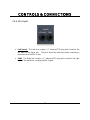
1
HP6
HP
60
0
Six-C
Channeel Headdphone Mixinng Systtem
Userr’s Manuual
Verrsion 1.1
1
© 2007, PreSonnus Audio Elecctronics, Inc.
All Rights Reservedd.
PRESONUS LIMITED WARRANTY
PreSonus Audio Electronics Inc. warrants this product to be free of defects in material and
workmanship for a period of one year from the date of original retail purchase. This
warranty is enforceable only by the original retail purchaser. To be protected by this
warranty, the purchaser must complete and return the enclosed warranty card within 14 days
of purchase. During the warranty period PreSonus shall, at its sole and absolute option,
either repair or replace, free of charge, any product that proves to be defective on inspection
by PreSonus or its authorized service representative. To obtain warranty service, the
purchaser must first call or write PreSonus at the address and telephone number printed
below to obtain a Return Authorization Number and instructions of where to return the unit
for service. All inquiries must be accompanied by a description of the problem. All
authorized returns must be sent to the PreSonus repair facility postage prepaid, insured and
properly packaged. PreSonus reserves the right to update any unit returned for repair.
PreSonus reserves the right to change or improve the design of the product at any time
without prior notice. This warranty does not cover claims for damage due to abuse, neglect,
alteration or attempted repair by unauthorized personnel, and is limited to failures arising
during normal use that are due to defects in material or workmanship in the product. Any
implied warranties, including implied warranties of merchantability and fitness for a
particular purpose, are limited in duration to the length of this limited warranty. Some states
do not allow limitations on how long an implied warranty lasts, so the above limitation may
not apply to you. In no event will PreSonus be liable for incidental, consequential or other
damages resulting from the breach of any express or implied warranty, including, among
other things, damage to property, damage based on inconvenience or on loss of use of the
product, and, to the extent permitted by law, damages for personal injury. Some states do
not allow the exclusion of limitation of incidental or consequential damages, so the above
limitation or exclusion may not apply to you. This warranty gives you specific legal rights,
and you may also have other rights, which vary from state to state. This warranty only
applies to products sold and used in the United States of America. For warranty information
in all other countries please refer to your local distributor.
PreSonus Audio Electronics, Inc.
7257 Florida Blvd.
Baton Rouge, LA 70806
www.PreSonus.com
© 2007, PreSonus Audio Electronics, Inc.
All Rights Reserved.
TABLE OF CONTENTS
1 OVERVIEW
1.1 Introduction .......................................................................................... 1
1.2 Features ............................................................................................... 2
1.3 What is in the Box ................................................................................ 3
2 OPERATION
2.1 Quick Start Up ...................................................................................... 4
2.2 Sample Hook Up Diagram ..................................................................... 6
3 CONTROLS & CONNECTIONS
3.1 Front Panel Layout ............................................................................... 7
3.1.1 Master Input Controls ..................................................................... 7
3.1.2 Headphone Channels: Level Controls .............................................. 8
3.2 Back Panel Layout ................................................................................ 9
3.2.1 Power ............................................................................................ 9
3.2.2 Headphone Channels: Rear Connections ....................................... 10
3.2.3 Talkback ...................................................................................... 11
3.2.4 Mix Inputs ................................................................................... 12
4 TECHNICAL INFORMATION
4.1 Specifications ..................................................................................... 13
4.2 Troubleshooting .................................................................................. 15
OVE
ERVIE
EW
1.1 IN
NTRODU
UCTION
Thank you
y
for purrchasing thee PreSonus HP60 Sixx-Channel Headphone
H
Mixing Sysstem.
PreSonuus Audio Electronics has
h designed the HP60 utilizing high-grade components to
ensure optimum
o
peerformance that will laast a lifetim
me. We believe
b
the HP60 to be
b an
exceptionnal sounding
g unit and an
a exceptional value.
We encourage you to
o contact uss at 1-800-7
750-0323 with
w any quesstions or comments youu may
have reggarding you
ur PreSonuss equipmentt. PreSonuus Audio Electronics
E
is committeed to
constant product im
mprovement,, and we vaalue your suuggestions highly.
h
We believe the best
way to achieve
a
our goal
g
of consstant producct improvem
ment is by lisstening to thhe real expeerts –
our valueed customerrs. We apprreciate the support
s
you have shownn us throughh the purchaase of
your HP60 Six-Channel Headphhone Mixingg System.
p
close attention
a
to how you connect your HP60 to
t your system. Imprroper
Please pay
groundinng is the most
m
common cause of
o noise problems fouund in studio or recording
environm
ments. We suggest you use this manual to familiarize yourself with the feattures,
applications and corrrect connecction proceddure for youur HP60 beefore trying to connect it to
your com
mputer. This will hopeffully alleviatte any unforreseen issuees you may encounter
e
during
setup andd use.
1
OVERVIEW
1.2 FEATURES
The PreSonus HP60 is the most flexible and advanced headphone mixing system designed for
the professional and project recording studio. The HP60 features dual stereo inputs and
external input for each channel -- allowing the user to mix between three stereo audio streams
(mix A, mix B & external input). Stereo output is also available on each channel to send line
level headphone channel mixes to additional headphone amplifiers or monitor systems. Each
channel features headphone level, mix between A and B inputs, external input volume, mute
and mono. The HP60 also features talkback via external XLR microphone. The HP60 is the
ultimate headphone amplification system delivering loud and clear headphone mixes for realworld recording situations.
Summary of features:
•
•
•
•
•
•
•
Six independent ultra-low noise and high output headphone amplifiers
Two sets of stereo inputs (A and B) with balanced TRS connectors
Stereo external input point on each channel for “more me” control
Mix control between inputs A and B on each channel
Talkback with external XLR microphone
Direct stereo line output on each channel
Mute and mono buttons on each channel
2
OVE
ERVIE
EW
1.3 WHAT
W
IS IN THE BOX
Your HP
P60 packagee contains thhe following:
• PreSonnus HP60
• HP60 User’s
U
Manuual v1.0
• 6’ Stanndard IEC Power
P
Cable
• PreSonnus Warrantty Card
3
OPERATION
2.1 QUICK START GUIDE
The goal of the HP60 Quick-Start guide is to help get your HP60 connected to your system as
quickly as possible. The following step-by-step instructions are based on a common studio
environment. Your actual setup may change based on your needs and applications.
Connect the Power
1) Turn every knob on the HP60’s front panel completely counterclockwise (left).
2) Connect the included IEC power cable to the HP60’s power input connector and to the
appropriate wall socket.
3) Flip the power switch to the ‘ON’ position (|= on).
Mix A, Mix B & Talkback Mic Connection and Level Adjustment
4) Connect your DAW (digital audio workstation) or Mixer Main Outputs to the Left and
Right TRS inputs of Input A on the back of your HP60.
5) Connect your DAW or Mixer auxiliary outputs (monitor mix / click track) to the Left
and Right TRS inputs of Input B on the back of your HP60.
6) Connect an XLR dynamic microphone to the MIC input on the back of your HP60.
7) Connect a pair of headphones to the Phones 1 output and turn its Level knob up to the
“12 o’clock position”.
8) Play a CD, session or other audio type typical to your studio through the source of
Input A (DAW or Mixer Outputs) and begin turning up the Input A knob until your
headphones are slightly above a comfortable / desired level.
9) Turn the Channel 1 Mix knob fully clockwise (right). Repeat steps 7 & 8 for Input B
and the Talkback Microphone (You will need to press ‘Talk’ when setting mic level).
4
OPERATION
External Input connection
10) For each of the headphone channels, connect the artist’s instrument direct out from
your DAW or Mixer to the Stereo Ext. In connection on their respective channels.
(For Example: If a vocalist is on headphone channel 5, take the direct output of
their vocals from your DAW or Mixer and connect it to the channel 5 Stereo Ext. In.
Likewise, if a guitar player is on headphone channel 2, take the direct output of their
guitar from your DAW or Mixer and connect it to the channel 2 Stereo Ext. In.)
Stereo Output Connection
11) If you have additional headphone amplification or monitoring systems or need a copy
of your mixes for any reason, connect a stereo ¼” TRS plug to the Stereo Out
connections of the mixes being copied and to the input of your additional system.
Headphone Connection
12) Connect headphones to the six Phones outputs on the front of your HP60.
Adjusting the HP60 for the “Optimum Listening Level”?
A common situation when setting up monitor mixes is when an artist’s headphones are turned
all the way up and they still feel they don’t have enough level. If you turn up the Input A/B
source, the other headphones will need to be turned down or remixed. So, what do you do?
By pre-setting the Input level to be loud enough at the “12 o’clock position” (step 7), you
ensure if an artist needs more level, you will have plenty of room to compensate for their
needs. This also gives you a good, generic point to which you can set an artist’s headphone
level before learning their desired listening volume.
An alternate method is to set the HP60 to reach its maximum attainable volume. To do this,
repeat steps 7-9 with the headphone level fully clockwise. Instead of paying attention to the
volume of the headphones, turn the Input level up until just before the signal distorts. This
means if an artist needs more volume, you can politely tell them you are already maxed out.
5
OPERATION
2.2 SAMPLE HOOKUP DIAGRAM
6
CONTROLS & CONNECTIONS
3.1 FRONT PANEL LAYOUT
The front panel of the HP60 is divided into two sections: the Master Input Controls and the
six numbered Headphone Channel Controls.
3.1.1 Master Input Controls
•
Input A & Input B. These knobs control the input levels of the Input A and Input B
(Mix A & Mix B) inputs on the rear of the chassis into the HP60. These two mixes
can be separately mixed together on each headphone output channel.
•
Talkback Level. This knob controls the input level of the external XLR dynamic
microphone connected to the MIC input on the rear of the chassis.
•
Talk. When the Talk button is pressed, the Talkback microphone input is activated.
This is a momentary type switch – the microphone is ‘ON’ only while the button is
pressed. An external foot pedal connected to the External Control input on the rear
of the chassis can also be used to activate the Talkback microphone.
7
CONTROLS & CONNECTIONS
3.1.2 Headphone Channels: Level Controls
•
Ext In. The external in knob controls the input level and amount of the Stereo Ext.
In on the rear of the chassis for the channel.
•
Mono. When the Mono button is pressed, the Stereo Ext. In will act as a mono
input – summing the signals from the TIP and the RING of the ¼” connection.
•
Mix. The Mix knob controls the amount of each of the two mixes A & B for the
channel. As the knob is turned counterclockwise (left), the amount of Mix A
increases, and the amount of Mix B decreases. As the knob is turned clockwise
(right), the amount of Mix A decreases, and the amount of Mix B increases. With
the Mix knob in the “12 o’clock position,” an equal amount of Mix A and Mix B is
sent to the channel’s headphones.
•
Mute. When the Mute button is pressed, both Mixes are muted for the channel.
This is most commonly used as a type of “Solo” for the external stereo input.
•
Level. The Level knob controls the volume level of the channel’s Phones output.
•
Phones. This is the channel’s stereo headphone output.
8
CONTROLS & CONNECTIONS
3.2 BACK PANEL LAYOUT
The back panel of the HP60 is divided into four sections: Power, the six numbered
Headphone Channels, Talkback and Inputs A & B.
3.2.1 Power
Power. The Power switch turns the HP60 on and off. The ‘ | ’ down is the ON position.
IEC Power Input. The HP60’s power input connection accepts a standard IEC plug and is
rated for either 100-120 VAC or 220-230 VAC, depending upon the country it is
purchased in. Please check with your local retailer or dealer if you have any questions
concerning the input voltage of your HP60’s power supply.
9
CONTROLS & CONNECTIONS
3.2.2 Headphone Channels: Rear Connections
•
Stereo Ext. In. The Stereo External In jack accepts a stereo ¼” TRS plug and is
used for connecting a third, channel-specific Mix. This is commonly used for a
direct input of the artist’s instrument – allowing the channel’s Ext. In knob to act as
a “more me” control.
•
Stereo Out. The Stereo Out jack carries a line-level copy of the channel’s
headphone mix and is commonly used for connecting to additional headphone
amplification systems, an additional monitor mixer or even a recording system. The
Stereo Out level is not affected by the channel’s Level knob.
10
CONTROLS & CONNECTIONS
3.2.3 Talkback
•
External Control. The External Control jack accepts a ¼” TS plug and is used for
connecting a footswitch to control the ON / OFF toggle of the External Mic.
•
MIC. The MIC input accepts a balanced XLR input and is used for connecting a
dynamic microphone to be used as the talkback microphone with the HP60’s
Talkback Communication System.
11
CONTROLS & CONNECTIONS
3.2.4 Mix Inputs
•
Left (mono). The Left jack accepts a ¼” balanced TRS plug and is used for the
left input of the stereo pair. This jack should be used alone when connecting a
mono source as the Mix’s Input.
•
Right. The Right jack accepts a ¼” balanced TRS plug and is used for the right
input of the stereo pair carrying the Mix’s signal.
12
TECHNICAL INFORMATION
4.1 SPECIFICATIONS
Audio Inputs
Dynamic Microphone Input
Type ........................................................................................ XLR Female Balanced
Input Impedance ............................................................................................. 1200Ω Maximum Gain .................................................................................................. 50dB
Maximum Input Level .................................................................................... -10dBu
Frequency Response . ................................................................ 10Hz to 40kHz, ±1dB Input A & Input B (Left & Right)
Type .............................................................................................. ¼” TRS Balanced
Input Impedance ............................................................................................... 10kΩ Gain Range ........................................................................................... -96 to +10dB External Inputs 1‐6 Type ................................................................................ ¼” TRS Stereo Unbalanced
Input Impedance ............................................................................................... 10kΩ Gain Range ........................................................................................... -96 to +10dB Audio Outputs
Headphone Outputs 1‐6 Type ........................................................................................ ¼” TRS Active Stereo
Maximum Output .......................................................... 150mW/channel @ 60Ω Load
THD+N ....................................................... ≤ 0.05% (150mW/channel @ 60Ω Load)
Frequency Response ................................................................. 10Hz – 70kHz, ± 1dB
Stereo Outputs 1‐6 Type ................................................................................ ¼” TRS Stereo Unbalanced
Output Impedance . .............................................................................................. 50Ω
13
TECHNICAL INFORMATION
Internal Linear Power Supply
Type ....................................................................................................................... IEC
Input Voltage Range ................................... 100-120 VAC or 220-230 VAC (factory set)
Power Requirements (continuous) .................................................................... 30 Watts
Physical
Package Type ................................................................ 1U Steel and Aluminum Chassis
Dimensions .................... 19" (W) x 1.75" (H) x 5.5" (D) (48.26cm x 4.45cm x 13.97cm)
Weight ............................................................................................ Approximately 5 lbs.
As a commitment to constant improvement, PreSonus Audio Electronics, Inc. reserves the
right to change any specification stated herein at any time in the future without notification.
14
TECHNICAL INFORMATION
4.2 TROUBLESHOOTING
If you experience any problems with your HP60, please try the following before contacting
PreSonus Customer Support:
1) Check our Web site at www.PreSonus.com for answers to frequently asked questions
and for troubleshooting techniques specific to the HP60.
2) Power cycle and disconnect / reconnect your HP60 power cable.
3) Check your connection cables and audio source(s).
4) Check your headphones.
5) Isolate the problem to your HP60 by disconnecting any extraneous equipment in
your signal chain.
For technical assistance, visit our Web site at www.PreSonus.com, call us at 225.216.7887
between 9am and 6pm CST (GMT -06:00) or e-mail us at [email protected].
When contacting technical support, please have the following information at hand:
¾ A brief description of what connections are being made to your HP60.
¾ The desired application of your HP60 in your studio environment.
¾ Your HP60 serial number (located on the bottom of your
15
unit).