1
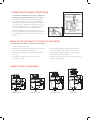
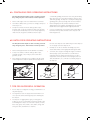
2a. INSTALLATION OF 3-BOLT MOUNTING ASSEMBLY
For TP-50, TP-75 and TP-125 models. Read completely before starting
NB - Pay close attention to the order of mount assembly parts,
as they have been correctly assembled by the factory.
(See A and B.)
3-Bolt Mount System
SINK FLANGE
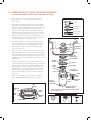
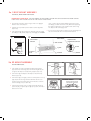
ADisassemble the mounting assembly, as it has been shipped,
by turning the sink flange until the projections align with the
notches in the mount ring and allow you to pull the sink flange
up and out of the remaining mount assembly. Note the
sequence of these parts as they are stacked and refer to A
and B to identify each part. Unpack the 3 mount screws and
screw them half way through the mount ring (notice “THIS
SIDE UP” is imprinted on top of the mount ring). Next, stack
the rubber gasket on top of the protector ring and sit them on
top of the pointed ends of the mount screws.
BKeep these assembled parts together and set aside. Before
you connect the disposer to the mount assembly under the
sink, you may want to practice engaging the groove of the
cushion ring to the ridge at the bottom of the sink flange
(see A and read Sec. 5).
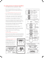
CBe sure your sink is clean. Pack the underside rim of the sink
flange with plumber’s putty (see C). Position the sink flange so
it is centered and readable as you look into your sink. Push the
sink flange firmly into the sink opening to make a good seal.
DO NOT move or rotate the sink flange once seated or the seal
may be broken.
DTake the remaining portion of the mount assembly, as it was
set aside and make sure that the rubber gasket is on top of the
3A
SINKholding the sink
protector ring. From under the sink, while
flange firmly with one hand, line up the notches in the mount
STOPPER*
ring with the projections of the sink flange. Slide the mount
assembly up onto the sink flange, past the projections and
SINK FLANGE**
give the mount assemblyPLUMBER’S
a 1/4 turn, so that it will hang by
PROJECTIONS
PUTTY
itself (see D).
SINK FLANGE GASKET
PROTECTOR RING
MOUNTING SCREWS (3)
SINK MOUNT RING
3A
B
SINK
STOPPER*
SINK FLANGE**
PLUMBER’S
PUTTY
PROJECTIONS
RIDGE
RUBBER SINK
FLANGE GASKET**
PROTECTOR RING**
MOUNTING
SCREWS**
MOUNT RING**
SCREW
CLAMP**
CUSHION RING**
RIDGE
DISHWASHER
DISCHARGE INLET
HOPPER
SCREWS
RIDGE
ELBOW
FLANGE
ETighten the 3 mounting screws evenly with a screwdriver
RUBBER SINK
FLANGE GASKET**
(see E). DO NOT OVERTIGHTEN! Trim off excess putty.
PROTECTOR RING**
MOUNTING
SCREWS**
Mount Assembly
MOUNT RING**
SCREW
CLAMP**
RIDGE
PROTECTOR
RING
SCREW
CLAMP
A
3B
CUSHION RING**
SINK
FLANGE
HOPPER
PROTECTOR
RING
DISHWASHER
DISCHARGE INLET
SCREWS
RUBBERELBOW
FLANGE
GASKET
ELBOW
GASKET
END BELL
(ELECTRICAL
CONNECTIONS)
END BELL
(ELECTRICALMount Assembly
CONNECTIONS)
ELBOW
GASKET
SINK
FLANGE
DISCHARGE
ELBOW
3B
SERIAL #- RECORD
RUBBER ON
WARRANTY GASKET
CARD
SCREW
CLAMPStopper looks different than the stopper
MOUNTING
* Batch Feed
illustrated.
SCREWS
** Mount Assembly (see 2B)
CUSHION RING
DISCHARGE
ELBOW
MOUNTING
RING
MOUNTING
SCREWS
SERIAL #- RECORD ON
WARRANTY CARD
MOUNTING
Feed Stopper looksRING
different than the stopper illustrated.
CUSHION RING*** Batch
Mount Assembly (see 2B)
3C
3D
C
3C
3E
D3D
E3E