1
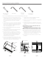
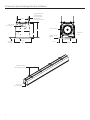
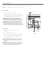
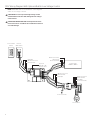
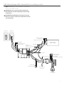
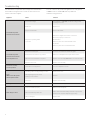
INSTRUCTION BOOK FOR
Tensioned Large
Advantage® Electrol®
Important Safety Instructions
Case Installation
When using your video equipment, basic safety precautions
should always be followed, including the following:
1. 1.Read and understand all instructions before using.
2.Position the cord so that it will not be tripped over, pulled,
or contact hot surfaces.
3. If an extension cord is necessary, a cord with a current rating
at least equal to that of the appliance should be used. Cords
rated for less amperage than the appliance may overheat.
4. To reduce the risk of electric shock, do not disassemble this
appliance. Contact an authorized service dealer when repair
work is required. Incorrect reassembly can cause electric
shock when the appliance is used subsequently.
5. The use of an accessory attachment not recommended
by the manufacturer may cause a risk of fire, electric shock,
or injury to persons.
2. Tighten bolts until trim flange is flush with ceiling.
1/8“ Hex Key
(included)
NOTE: Please Note: Motor Operator Projection Screen
Models LADT, LADDT, LAD and LADD must be installed in
accordance with the requirements of the Local Building
Codes, the Canadian Electrical Code (CEC), CAN/CSA C22.1
and the National Electric Code (NEC), NFPA 70. An
appropriate disconnect device shall be provided as part of
the building installation.
If your case was ordered in advance of the screen and roller
assembly, your installation is now complete. Continue to
step 4 if your Tensioned Large Advantage Electrol was
ordered as a complete unit.
4. Carefully remove paper and tape from roller assembly
CAUTION! Do not use a knife or sharp object to cut tape;
you will damage the screen. Pull orange string.
ATTENTION! Ne coupez pas le ruban adhésif sur la toile
avec un couteau ou un outil tranchant. Retirez à la main.
5.
Use supplied 1/8" hex key to remove silver shipping brackets
attached to slat and screen case.
Pre-Installation
1. Carefully unpack case from shipping crate.
2. Set aside the Installation Kit. Items inside will be used during
installation.
3. Make sure to recheck measurement of case for proper
installation clearance.
4. Remove any protective foam from case.
5. If necessary. adjust hanger brackets with a 3/4" open wrench
or socket driver.
2
NOTE: For proper operation, screen assembly must be level
after installation.
3. Remove 2 screws to open junction box. Install electrical
connections that apply to your unit. Make sure to review the
wiring diagram for proper hook up. Replace junction box
cover and secure with 2 screws.
Tools Required for Installation
3/4“ Open Wrench
or Socket Driver
The case provides multiple attachment points for bolts,
cables, or threaded rod. Page 4 shows threaded rod
installed. The variable position-mounting bracket may be
located anywhere along the length of the case. It is
recommended to keep the brackets spaced evenly enough
to distribute the weight of the screen. One mounting bracket
is required for every 4' of case length.
6. Test installation by running screen up and down a few times.
Be prepared to stop screen should any objects obstruct the
movement of the screen. To prevent damage to the motor,
the standard duty cycle is 1 minute on and 3 minutes off.
Screen And Roller Assembly Installation
Tools required for screen and roller assembly:
9/16“ Open Wrench
or Socket Driver
1/8“ Hex Key
(included)
5/32“ Hex Key
1/2“ Open Wrench
or Socket Driver
If your screen was shipped with the motor and roller already installed proceed to step 7.
1. Remove the access door. First, remove the 2 bolts from each
end with a 9/16" open wrench or socket driver. Next, use a 5/32"
hex key to remove the two screws in the center of the access
door. This will allow the door to drop open on the hinges
(Figure 1).
2. Carefully unpack screen and roller assembly. Use supplied 1/8"
hex key to remove shipping brackets attached to slat. Remove
fabric and roller assembly from shipping board using a 1/2"
wrench. Leave packing paper on roller.
3. Remove the square peg bracket from the motor end of the
roller assembly (Figure 2).
4. Remove the safety clip from the motor attachement bracket
located in the motor end of the screen housing.
5. Use a 1/2" open wrench or socket driver to loosen the four
bolts that secure pin end mounting bracket into housing. Lift
pin end of roller into position and slide the bracket into the
roller pin. Tighten all four bolts. Slide the pin end bracket
towards the end of the case (Figure 3).
7. Complete electrical hook-up by snapping motor 1/3 wire
connectors into case connectors (Figure 2).
8. Return to motor end and insert safety clip over casting bracket
to secure motor end.
9. Carefully remove tape strips securing picture surface around
roller. Slat should move freely. (Only if the roller assembly is pre
installed.)
CAUTION! Do not cut tape on fabric with a knife or any
sharp tool. Remove by hand.
ATTENTION! Ne coupez pas le ruban adhésif sur la toile
avec un couteau ou un outil tranchant. Retirez à la main.
10. Test installation by running screen up and down a few times.
Be prepared to stop screen should any objects obstruct the
movement of the screen. To prevent damage to the motor, the
standard duty cycle is 1 minute on and 3 minutes off.
11. Re-install the access door. Procedure is the reverse of step 1
listed above.
6. Place the roller assembly into the case with the motor on the
left side. The limit switches should be facing down. Line up the
head of the motor with the motor attachment bracket.
LVC Control Box
Bolts
Door Support
Screws
Access
Door
Bolts
Screen Motor
Figure 1
Screen Motor
Limit Switches
Figure 2
Bolts
Figure 3
3
Tensioned Large Advantage® Electrol® Installation
9 1/8"
(Suggested) 1/2"
Threaded Rod
(Not Included)
Attached to
Mounting Bracket
Electrical
Junction Box
12 3/16"
Screen Roller
11"
Audience
Side
11 7/16"
Self-Trimming
Flange
Finished
Ceiling
Self-Trimming
Flange
13 1/8"
Variable Position
Mounting Brackets
Electrical
Junction Box
4
Access Door
2 3/16"
10 15/16"
Screen Adjustment
Surface travel is stopped automatically in the fully opened and closed positions by limit switches that are properly adjusted at Da-Lite.
Should it be necessary to adjust for more or less drop of picture, proceed in the following manner:
NOTE: Use a screw driver or 5/32" Allen wrench to make adjustments.
More Screen Drop
1.Place operating switch in “down” position.
LVC Control Box
2.When the screen stops, turn the white “down” limit knob
(Figure 4) one-quarter turn counterclockwise. Test by raising
picture surface approximately two feet, then lower again. Repeat
until desired picture surface position is attained.
CAUTION: Do not adjust for more drop than what was
ordered. At least 1-1/2 wraps of fabric must remain on the
roller. This screen comes standard with 12" black at the top.
ATTENTION! N'effectuez pas de réglage pour obtenir un
déroulement supérieur à celui commandé. Au moins 1 à 1/2
tour de toile doit être maintenu sur le cylindre. Ce écran est
doté de série d'une bande noire supérieure de 30,5 cm (12 po).
Less Screen Drop
1.Raise picture surface approximately two feet above
desired level.
2.Place operating switch in “off” position.
Screen Motor
Screen Motor
Limit Switches
Figure 4
3.Turn the white “down” limit switch (Figure 4) one-quarter turn
clockwise. Test by raising picture surface approximately two
feet, then lower again. Repeat until desired picture surface
position is attained.
Caution: Adjusting the down limit switch for less drop by
more than 6” can cause the screen surface to lose proper
tensioning.
ATTENTION! Le fait d'ajouter ne déroulez pas trop l'écran
plus de 15 cm (6po) aux interrupteurs de fin de course peut
faire perdre la bonne tension à la surface de l'écran.
5
120V Wiring Diagram With Optional Built-In Low Voltage Control
NOTE: 20-24 AWG wire recommended for connecting wall
switch to low voltage controller.
CAUTION: Do not use 3-position high voltage rocker
switch with this unit! This will damage the low voltage
control board.
ATTENTION: NE UTILISEZ PAS l'interrupteur à bascule
fourni avec l'écran. Le tableau de contrôle basse tension
sera endommagé.
Back of
Front of Wall
Wall Switch
Switch
Red (Up)
White (Common)
Black (Down)
White (Common)
Black (Hot)
Green (Ground)
Power Input
120VAC / 60Hz
Eye Port:
Plug IR or RF
Remote Here
White (Common)
Black (Down)
Red (Up)
White (Common
Black (Down)
Red (Up)
Green (Ground)
Green (Ground)
Screen Motor
6
240V Wiring Diagram With Optional Built-In Low Voltage Control
NOTE: 20-24 AWG wire recommended for connecting wall
switch to low voltage controller.
CAUTION: Do not use 3-position high voltage rocker
switch with this unit! This will damage the low voltage
control board.
ATTENTION: NE UTILISEZ PAS l'interrupteur à bascule
fourni avec l'écran. Le tableau de contrôle basse tension
sera endommagé.
Front of
Wall Switch
Back of
Wall Switch
Blue (Common)
Brown (Hot)
Green/Yellow (Ground)
Red (Up)
White (Common)
Black (Down)
Power Input
120VAC / 60Hz
Wire Nut
Eye Port:
Plug IR or RF Black
Remote Here
Wire Nut
Blue (Common)
Blue (Common
Brown (Down)
Black (Up)
Green/Yellow (Ground)
Black (Up)
Brown (Down)
Green/Yellow
(Ground)
Screen Motor
7
Troubleshooting
Visit www.da-lite.com/products/tutorials.php to find installation
and troubleshooting tutorials. You will also find a link to Live
Chat for interactive support.
Symptom
You can contact us by email at [email protected] or by phone
at 800.622.3737 or 574.267.8101 with any additional
troubleshooting questions.
Cause
Solution
Incorrect line voltage.
Verify 115-125V (or 220-240V). If insufficient voltage, rewire
incoming electric line.
Blown fuse.
Replace fuse.
Tripped circuit breaker.
Reset circuit breaker.
creen will not operate
S
and motor does not hum.
Check above. Tighten all loose wire connections.
Correct any improper connections.
No power to operating switch
or junction.
Down Position
Check for power across black and white leads.
Up Position
Check for power across red and white leads.
Thermal overload tripped.
Let motor cool down for 15 minutes. Try again.
Screen will not operate
and motor does not hum.
Broken wire in the “down” or “up” position.
Check for continuity. Cut off old splice and reconnect.
Power at junction box.
Defective motor, limit switch or capacitor.
Replace motor assembly. NOTE: Motor is a sealed assembly.
Capacitor burned out.
Replace motor assembly.
Limit switch out of adjustment.
See Screen Adjustment section.
Squeaking, rubber end plug rubbing on motor.
Center roller in case.
rinding. Foreign object in screen
G
rubbing on roller or fabric.
Remove.
Gear noise.
Replace motor assembly.
Defective brake.
Replace motor assembly.
Screen not installed properly.
Check for level and plumb.
Fabric has backed up inside case.
djust “down” limit switch slowly until roller is exposed and
A
wrinkle comes out, then readjust for proper drop.
Fabric is damaged.
Replace fabric.
Screen does not stop
at correct position.
Noise.
NOTE: Screen will operate
with a low pitched hum.
Coasting.
Fabric hangs crooked.
8
9
10
11
LIMITED FIVE YEAR WARRANTY ON DA-LITE TENSIONED ADVANTAGE® ELECTROL®, ADVANTAGE® ELECTROL®,
TENSIONED LARGE ADVANTAGE® ELECTROL®, LARGE ADVANTAGE® ELECTROL®, TENSIONED CONTOUR® ELECTROL®
AND CONTOUR® ELECTROL® PRODUCTS ONLY
Milestone AV Technologies LLC warrants these Da-Lite branded products to the original purchaser only, to be free from defects in materials and
workmanship for a period of five (5) years from the date of purchase by the original purchaser; provided they are properly operated according
to Da-Lite’s instructions and are not damaged due to improper handling or treatment after shipment from the factory.
This warranty does not apply to equipment showing evidence of misuse, abuse or accidental damage,
or which has been tampered with or repaired by a person other than authorized Da‑Lite personnel.
Da-Lite’s sole obligation under this warranty shall be to repair or to replace (at Da-Lite’s option) the defective part of the merchandise. Returns
for service should be made to your Da-Lite dealer. If it is necessary for the dealer to return the screen or part to Da-Lite, transportation expenses
to and from Da-Lite are payable by the purchaser and Da-Lite is not responsible for damage in shipment.
To protect yourself against damage or loss in transit, insure the product and prepay all transportation expenses.
TO THE MAXIMUM EXTENT PERMITTED BY APPLICABLE LAW, THIS WARRANTY IS IN LIEU OF ALL OTHER WARRANTIES, EXPRESS
OR IMPLIED, INCLUDING WARRANTIES AS TO FITNESS FOR USE AND MERCHANTABILITY. Any implied warranties of fitness for use, or
merchantability, that may be mandated by statute or rule of law are limited to the five (5) year warranty period. This warranty gives you specific
legal rights, and you may also have other rights, which vary from state-to-state. TO THE MAXIMUM EXTENT PERMITTED BY APPLICABLE
LAW, NO LIABILITY IS ASSUMED FOR EXPENSES OR DAMAGES RESULTING FROM INTERRUPTION IN OPERATION OF EQUIPMENT,
OR FOR INCIDENTAL, DIRECT, OR CONSEQUENTIAL DAMAGES OF ANY NATURE.
In the event that there is a defect in materials or workmanship of a Da-Lite product, you may contact our Sales Partners at PO Box 137, Warsaw,
IN 46581-0137, (574) 267-8101, (800) 622-3737.
IMPORTANT: THIS WARRANTY SHALL NOT BE VALID AND DA-LITE BRANDED PRODUCTS SHALL NOT BE BOUND BY THIS
WARRANTY IF THE PRODUCT IS NOT OPERATED IN ACCORDANCE WITH THE DA-LITE WRITTEN INSTRUCTIONS.
Keep your sales receipt to prove the date of purchase and your original ownership.
A Milestone AV Technologies Brand
3100 North Detroit Street
Warsaw, Indiana 46582
P: 574.267.8101 or 800.622.3737
F: 574.267.7804 or 877.325.4832
E: [email protected]
www.da-lite.com
DL–0123 (Rev. 2) 04.14
© 2014 Milestone AV Te chnologies LLC. Printed in U.S.A.
35890