Transcript
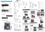
DS57U Quick Guide【 English 】 __p Front Panel F1 F2 F3 Motherboard Illustration Back F1. USB2.0 Ports x4 AC Back Auto Power ON J4 F3. HDD LED F6 F4. Power Button Pin 1 2 F5. COM 1 : Support RS232/RS422/RS485 SD Card Reader FFC Connector - CON3 F6. COM 2 : Support RS232 F4 JP7 Signal Name U26C_pin10 GND 2 4 1 3 Pin 1 2 3 4 2 1 Safety Information Super I/O F7. SD Card Reader External Power SW & Clear CMOS DEFAULT =>Disable, short 1-2 F2. Power LED F5 J5 Read the following precautions before setting up a Shuttle XPC. SW2 Signal Name PWRSW+5V GND RTC_RST# Note Pin 1+3 3+4 Function Power Button Clear CMOS CAUTION F7 ® Incorrectly replacing the battery may damage this computer. Replace only with the same or equivalent as recommended by Shuttle. Dispose of used batteries according to the manufacturer's instructions. ® Intel Celeron / Core i series processor Back Panel B1.External Power & Clear CMOS (Pin definition J5 ) A. Begin Installation B2.DisplayPort B3.HDMI Port C. Component Installation For safety reasons, please ensure that the power cord is disconnected before opening the case. B4.MIC In Jack B5.Headphone Jack 1. Unscrew the rack from chassis. 1. Unscrew two screws of the chassis cover. B6.USB3.0 Ports x2 B7.LAN Ports x2 B1 B2 B3 B4 B5 B6 B7 B8 B8.DC IN Jumper Settings Left / Right Panel J1 Kensington® Lock COM Port 1 RS-232, RS-422, RS-485 switch by BIOS setting 1 2 3 4 5 Kensington® Lock 6 7 8 9 Pin 1 3 5 7 9 Motherboard Illustration Front Power Button - SW1 HDD LED Power LED COM Port 1 J2 eDP Panel Connector - EDP1 LAN Ports x2 MIC In JACK B. Memory Module Installation This mainboard does only support 1.35V DDR3L memory modules. 1. Locate the SO-DIMM slot on the mainboard. External Power SW & Clear J5 CMOS - SW2 HDMI Port COM1&COM2 Power Switch J3 2 4 6 8 10 1 3 5 7 9 Pin 1 3 5 7 9 J4 Half Size Mini PCIe with Wi-Fi card support - CON5 DisplayPort 3. Put the HDD in the chassis and push toward right until it insert into HDD slot. notch Support RS232 Back panel Independent External Power 12V / 5V JUMP1 Connector Pin 1-2 = RI1 Signal Enable. JUMP2 Connector Pin 3-4 = RI2 Signal Enable. IF JUMP1 Connector Pin 5-7 = RI1 is VCC (5V) IF JUMP2 Connector Pin 6-8 = RI2 is VCC (5V) IF JUMP1 Connector Pin 7-9 = RI1 is 12V IF JUMP2 Connector Pin 8-10 = RI2 is 12V Full Size Mini PCIe with mSATA, Wi-Fi card support - CON4 DDR3L SO-DIMM Slots USB 3.0 Ports x2 1 Use DDR3L SO-DIMM J1 J3 Headphone JACK Pin 1 3 5 7 9 COM1 (RS485) Signal Name Pin Signal Name Data2 Data+ --4 --GND 6 ----8 --RI- 2 Debug Header - DBG1 AC Back Auto Power ON (DEFAULT =>Disable, short 1-2) - JP7 DC IN COM1 (RS422) Signal Name Pin Signal Name TXD2 TXD+ RXD4 RXD+ GND 6 ----8 --RI- 2. Align the notch of the memory module with the one of the memory slot. COM1&COM2 Power Switch - JP1 J2 2.5 inch HDD Slot COM1 (RS232) Signal Name Pin Signal Name DCD 2 RX TX 4 DTR GND 6 DSR RTS+ 8 CTS+ RI- Pin 1 3 5 7 9 RTC Battery Connector - BAT1 COM Port 2 USB 2.0 Ports x4 2. Place the HDD in the rack and secure with two screws from the side. 2. Slide the cover forwards and upwards. JP1 Signal Name Pin -XRI1 2 -XRI2 4 +5V 6 COM1_PWR 8 +12V 10 4. Refasten screws. 3. Gently insert the module into the slot in a 45-degree angle. 4. Carefully push down the memory module until it snaps into the locking mechanism. Signal Name COM_-XRI1 COM_-XRI2 +5V COM2_PWR +12V 1 2 eDP panel connector Pin 1 4 7 10 13 16 19 22 Signal Name BKLTEN_R INV_PWR_SRC EDP_TX0_P GND EDP_TX1_P GND EDP_TX2_P GND Pin 2 5 8 11 14 17 20 23 25 28 PANEL_VDD 26 LCD_SELF_TEST 29 D. Complete 1. Replace covers and refasten screws. 45-degree angle EDP1 Signal Name INV_PWR_SRC EDP_TX0_N INV_PWR_SRC EDP_TX1_N EDP_HPD_G EDP_TX2_N EDP_TX3_P PANEL_VDD Pin 3 6 9 12 15 18 21 24 Signal Name GND INV_PWR_SRC GND GND GND EDP_TX3_N GND EDP_AUX_N EDP_AUX_P GND 27 30 PANEL_VDD EDP_BKL_CTL 30 28 26 24 22 20 18 16 14 12 10 8 6 4 2 29 27 25 23 21 19 17 15 13 11 9 7 5 3 1 3 2 . Complete. Latch Latch 5. Repeat above steps to install additional memory modules, if required. Please load the optimized BIOS setting. Operation Position: Please make sure to use either the supplied feet or the VESA mount. 53R-DS57U3-H011