Transcript
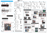
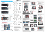
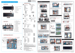
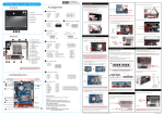
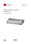
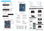
62R-DS8100-0601 English.Spanish.Korean. Traditional Chinese.Japanese. French. German Quick Guide DS81 Series Quick Guide【 English 】 __p Front Panel Jumper Settings F1.Mic-In C1 F2.Headphone F5 F6 F7 Power Button (SW3) C2 F3.Power LED F5.Power Button C3 F6.Card reader F4 Pin Assignments (CN1): 1=SPKR_OUT 2=GND B1.COM1 Port (RS232/RS422/RS485) C10 EDP Connector V1.0 Pin Assignments (CN25): Pin Assignments: 1=GND 2=GND 3=SDVO_CLK_D 4=GND 5=SDVO_DATE_D 6=GND 7=GND 8=GND 9=CRT_VSYNC_R 10=GND 1=PANEL_VDD 2=CAD_56B 3=PANEL_VDD 4=HPD_56B_C 5=PANEL_VDD 6=NC 7=PANEL_VDD 8=NC 9=PANEL_VDD 10=NC 11=GND 12=GND 13=EDP_BKLTCTL 14=AUX-_56B_C 15=EDP_BKLTEN 16=AUX+_56B_C 17=GND 18=GND 19=NC 20=D3-_56B_C 2 1 1 2 3 4 B2 B3.Power Jack (DC-in) C5 B4.LAN Ports B6.USB2.0 Ports B7. DisplayPort B5 B6 B7 B8 B8. HDMI Port B9 Audio Connector 11=CRT_HSYNC_R 12=GND 13=GND 14=GND 15=BOUT-O 16=VGA_PWR 17=GOUT-O 18=VGA_PWR 19=ROUT-O 20=VGA_PWR 20 19 A. Begin Installation Pin Assignments (AUDIO2): 1=PULL AGND 2=LINE-R 3=NC 4=LINE-L 5=PULL AGND 6=FRONT_L 7=NC 8=FRONT_SENSE 9=PULL AGND 10=FRONT_R 11=BK_AUDIO-JD 12=MIC1_R 13=AGND 14=MIC1_L B5.USB3.0 Ports B4 SPK1 VGA Connector C11 Battery connector Pin Assignments (CN1): 21=NC 22=D3+_56B_C 23=GND 24=GND 25=INV_PWR_SRC 26=D2-_56B_C 27=INV_PWR_SRC 28=D2+_56B_C 29=INV_PWR_SRC 30=GND 31=INV_PWR_SRC 32=D1-56B_C 33=INV_PWR_SRC 34=D1+56B_C 35=GND 36=GND 37=NC 38=D0-_56B_C 39=NC 40=D0+_56B_C 1=V_BAT 2=GND 40 C12 39 1 Clear CMOS&POWER BUTTON Pin Assignments (SW2): 1=RTCRST- 2=+5V 3=GND 4=PWRSW- 1 2 C13 2 1 SATA POWER connector Pin Assignments (PW1): 1=GND 2=GND 3=+5v 4=+5v 4 3 2 1 B2.COM2 Port (RS232 only) B1 B3 C4 Fan Connector Pin Assignments (FAN1): 1=GND 2=+12V 3=SPEED_SENSE 4=PWM_CTRL F7.USB2.0 Ports Back Panel USB Connector Pin Assignments : 1=GND 1 2 3 4 2=USB10P 3=USB10N 4=USBPW04 F4.HDD LED F1 F2 F3 C9 B9. Clear CMOS&POWER BUTTON 13 11 9 7 5 DO NOT touch socket contacts. To protect the CPU socket, always replace the protective socket cover when the CPU is not installed. For safety reasons, please ensure that the power cord is disconnected before opening the case. 1. Unscrew the two screws of the chassis cover. 5. Orientate the CPU and socket and please align the CPU notches with the socket alignment keys. Make sure the CPU is perfectly horizontal, insert it into the socket. 3 1 6 4 Notch on the CPU/ Alignment Key of the CPU Socket Socket 1155 CPU 2. Slide the cover backwards and upwards. 2 2 Left / Right Panel 1=DCD 2=RX 3=TX 4=DTR 5=GND 6=DSR 7=RTS 8=CTS 9=RI D. Component Installation 1. Install the Mini PCIE card into the Mini PCIE slot and secure with screw. 6. Close the metal load plate, lower the CPU socket lever and lock in place. 7. Spread thermal paste evenly on the CPU surface. COM PORT Pin Assignments (COM1&COM2): Kensington® Lock Port 5. Repeat the above steps to install additional memory modules, if required. Please be aware of the CPU orientation, DO NOT force the CPU into the socket to avoid bending of pins on the socket and damage of CPU! 1 C6 Latch Latch Triangle Pin1 Marking on the CPU 14 12 10 8 3 9 7 5 3 1 3. Unfasten the rack mount screw and remove the rack. Load lever 10 8 6 4 Retention tab 2. Place the HDD in the rack and secure with the four screws from the side. 2 10=NC Thermal Paste application area Metal load plate Kensington® Lock Port C7 Support RS232 Back panel Independent External Power 12V / 5V Please do not apply excess amount of thermal paste. HDD Rack (DEFAULT=SHORT 1-2,3-4) IF JUMP1 Connector Pin 5 and IF JUMP2 Connector Pin 6 and IF JUMP1 Connector Pin 7 and IF JUMP2 Connector Pin 8 and Motherboard Illustration C1 SW3 C2 C3 B. CPU and ICE Module Installation 7 = COM1 is +5V 8 = COM2 is +5V 9 = COM1 is +12V 10 = COM2 is +12V 9. Connect the fan connector. 1=-XRI1 3=-XRI2 5=+5V 7=COM1_PWR 9=+12V C4 Power LED USB FAN1 SPK1 Headphone USB 2.0 2=COM_-XRI1 4=COM_-XRI2 6=+5V 8=COM2_PWR 10=+12V 3. Connect the Serial ATA and power cables to the HDD. 1. Unfasten the four ICE module attachment screws and unplug the fan connector. 1 Pin Assignments (JP3): HDD LED Card Reader Slot Pin Pin Pin Pin 8. Screw the ICE module to the mainboard. Note to press down on the opposite diagonal corner while tightening each screw. Serial ATA Power Cable 3 Serial ATA Cable 20 19 4 2 Fan connector Fan connector MC In 2 1 Audio Connector C5 LGA1150 Package CPU Socket DDR3 SODIMM slots C8 C8 Mini PCIE Slot Serial ATA Connectors SATA3 COM 2 C6 COM 1 SATA6 C7 JP3 Intel H81 Chipset LPC C13 PW1 C8 CN25 C9 EDP C10 CN1 C11 Please note this 1150 pin socket bends easily. Always apply extreme care and little force when installing a CPU and limit the number of times you remove or exchange it. Before installation, make sure to turn off the computer and unplug the power cord from the mains to avoid damage. LPC connector Pin Assignments (LPC1): 1=CLK-33M 11=L_AD0 2=GND 12=GND 3=LFRAME 13=LPC_48M 4=NC 14=PCH_PME5=SIORST# 15=+3.3VS 6=-XRI3 16=SERIRQ 7=L_AD3 17=GND 8=L_AD2 18=+3.3V 9=+3.3V 19=+3.3V 10=L_AD1 20=SUS_CLK 2. Remove the ICE module from the chassis and put it aside. 20 19 C. Memory Module Installation 1. Locate the SODIMM slot on the mainboard. 2. Align the notch of the memory module with the one of the memory slot. notch SODIMM slot Cutout Follow the steps below to correctly install the CPU into the motherboard CPU socket. 3. Tear off the protective membrane first, then unlock and raise the socket lever. Remove the protective membrane 2 1 3. Gently insert the module into the slot in a 45-degree angle. 4. Carefully push down the memory module until it snaps into the locking mechanism. 4. Lift the metal load plate on the CPU socket. 1 Safety Information 4. Slide the rack in the chassis and refasten the screw. E. Complete 1. Replace the cover and refasten the screws. Read the following precautions before setting up a Shuttle XPC. 2 CAUTION DC IN LAN Ports USB3.0 (x2) Ports USB2.0 (x2) Ports Display Port HDMI Port C12 SW2 Incorrectly replacing the battery may damage this computer. Replace only with the same or equivalent as recommended by Shuttle. Dispose of used batteries according to the manufacturer's instructions. Metal load plate 45-degree angle 2 . Complete. Please load the optimized BIOS settings. LThe product’s color and specification will depend on the actual shipping product. 53R-DS8103-2001