1
- Consult the dealer or an experienced radio/TV
technician for help.
4. Compliance with Part 15 of FCC Rules and
Canadian ICES-003.
This device complies with Part 15 of the FCC Rules.
Operation is subject to the following two conditions:
(1) This device may not cause harmful interference,
and (2) this device must accept any interference
received, including interference that many cause
undesired operation.
This Class B digital apparatus complies with
Canadian ICES-003.
Cet appareil numérique de la classe B est conforme
à la norme NMB-003 du Canada.
Names and functions
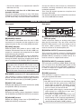
Front panel
Rear panel
❶ [POWER] indicator
❼ [ANALOG OUTPUT] (L and R) connectors
(RCA pin jacks)
❷ [LOCK] indicator
These connectors output an analog audio signal
after the D/A converter They are active when the
[OUTPUT SEL] switch on the front panel is set to
the down (“RCA”) position. Generally, They are
used to connect to an audio amplifier, etc.
This indicator is illuminated when the unit is USBconnected to a computer and the computer is supplying the power to the unit via the [USB] connector.
While the [INPUT SEL] switch is set to “USB”, this
indicator is illuminated when the HP-A3 is USB-connected to a computer and recognized as an digital
audio device by the computer.
While the [INPUT SEL] switch is set to “OPTICAL”,
this indicator is illuminated when the HP-A3 is receiving the S/PDIF signal from a digital audio device
that is connected to the [DIGITAL INPUT] connector.
❽ [DIGITAL OUTPUT] connector (optical)
This connector directly outputs a digital audio
signal being received by the unit (via the [USB] or
[DIGITAL INPUT] connector) in S/PDIF format. It is
used to connect to a digital audio device.
❾ [DIGITAL INPUT] connector (optical)
This connector receives an S/PDIF digital audio signal. It is active when the [INPUT SEL] switch on the
front panel is set to the up (“OPTICAL”) position. It
is used to connect to a digital audio playback device such as a CD player.
<Note>:Even though the [LOCK] indicator is illuminated while the [INPUT SEL] switch is set to
“USB”, if the audio output device of the computer is set to any device other than the HP-A3,
the HP-A3 does not receive an audio signal.
❿ [USB] connector
❸ [PHONES] connector (1/4” stereo phone jack)
This connector is used to connect to a computer
using the supplied USB cable.
This connector is used to connect to stereo headphones. It is active when the [OUTPUT SEL] switch on
the front panel is set to the up (“PHONES”) position.
<Memo>
• Via USB, the HP-A3 not only receives a digital
audio signal but also gets power (USB bus
power) from a computer. Therefore, always
make USB connection to your computer and
turn it on when you use the HP-A3.
• To get stable power supply, connect the USB
cable directly to a USB port of your computer, without using a USB hub.
• To receive a digital audio signal from your
computer via USB, you should make audio
output setting of the computer appropriately,
as well as setting the [INPUT SEL] switch of
the HP-A3 to the down (“USB”) position.
❹ [INPUT SEL] switch
Switches the digital input source between the [USB]
and [DIGITAL INPUT] connectors.
❺ [OUTPUT SEL] switch
Switches the analog output destination between
the [PHONES] and [ANALOG OUTPUT] connectors.
❻ [VOLUME] control
Adjusts the analog output level of [PHONES] and
[ANALOG OUTPUT] connectors.
E-4