1
Chapter 2: Installation
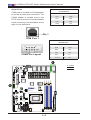
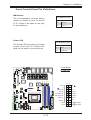
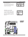
Unit Identifier Switch
UID Switch
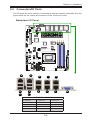
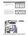
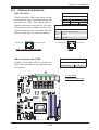
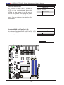
A Unit Identifier (UID) Switch and two LED
indicators are located on the motherboard. The
UID Switch is located next to the VGA port on
the backplane. The Rear UID LED (LED7) is
located next to the UID Switch. The Front Panel
UID LED is located at Pin 7 of the Front Control
Panel at JF1. Connect a cable to Pin 7 on JF1
for Front Panel UID LED indication. When you
press the UID switch, both Rear UID LED and
Front Panel UID LED Indicators will be turned
on. Press the UID switch again to turn off both
LED Indicators. These UID Indicators provide
easy identification of a system unit that may be
in need of service.
Pin#
Definition
1
Ground
2
Ground
3
Button In
4
Button In
UID LED
Status
Color/State Status
Blue: On
Unit Identified
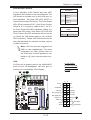
Note: UID can also be triggered via
IPMI on the motherboard. For more
information on IPMI, please refer to
the IPMI User's Guide posted on our
website @ http://www.supermicro.
com.
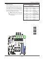
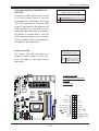
VGA
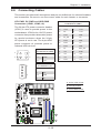
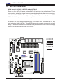
A. UID Switch
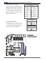
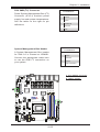
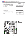
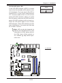
A VGA port is located next to the LAN6/LAN7
ports on the I/O backpanel. Use this port to
connect to a compatible VGA display.
B
B. Rear UID LED
C. Front UID LED
D. VGA
A D
LED7
JUIDB1
LED8
VGA
JBAT1
JL1
JOH1
JI2C2
JI2C1
JPCIE1 PCI-E 2.0X4
FAN3
T3
T1
LAN6/LAN7
LAN1/LAN2 LAN5 USB2.0 2/3 COM1
LAN3/LAN4
T7
T5 T19 T17 T23 T21 T11 T9 T15 T13
USB2.0 6/7
T4
T2
T8
JPG1
20
T6
T20 T18 T24 T22
T12 T10
DIMMA2
DIMMB1
A1SRM-LN7F/LN5F
REV:1.01
DESIGNED IN USA
USB 2.0-4/5
JPI2C1
SP1
JSTBY1
JF3
1
SRW3
JF2
LAN BYPASS LED
JTPM1
SRW1
J3
JPW1
SRW2
M_SATA
J4
I-SATA0
3.3V Stby
3.3V Stby
NIC6 Activity LED
3.3V Stby
UID LED
OH/Fan Fail
USB 2.0-1
I-SATA3
FAN2
FAN1
2-13
C
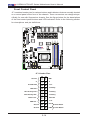
3.3V
Ground
Reset
Reset Button
Ground
PWR
Power Button
CPU
I-SATA4
I-SATA2
BIOS
LICENSE
JSD1
SATA DOM POWER
I-SATA5
JPW2
JF1
1 23
I-SATA1
JD1
HDD LED
NIC7 Activity LED
PWR Fail
JBT1
LED3
LAN 1/2/3/4/5 LED
BAR CODE
SRW4
X
3.3 V
FP PWR LED
COM2
JWD1
NMI
X
DIMMA1
DIMMB2
JIPMB1
LED2
19
Ground
T16 T14
2
1