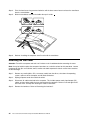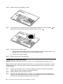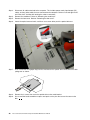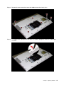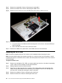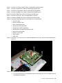
1
Lenovo C50 Series All-In-One Computer
Hardware Maintenance Manual
Machine Types: F0B1 [C50-30]
Lenovo C50 Series All-In-One Computer
Hardware Maintenance Manual
Machine Types: F0B1 [C50-30]
First Edition (November 2014)3rd
© Copyright Lenovo 2014.
LIMITED AND RESTRICTED RIGHTS NOTICE: If data or software are delivered pursuant a General Services
Administration “GSA” contract, use, reproduction, or disclosure is subject to restrictions set forth in Contract No.
GS-35F-05925
Contents
Chapter 1. About this manual . . . . .
1
Chapter 7. Replacing hardware . . . .
Important Safety Information . . . . . . . . .
1
Chapter 2. Safety information . . . . .
3
General safety . . . . . . . . . . . .
Electrical safety . . . . . . . . . . .
Safety inspection guide . . . . . . . .
Handling electrostatic discharge-sensitive
devices . . . . . . . . . . . . . .
Grounding requirements . . . . . . . .
Safety notices . . . . . . . . . . . .
. . .
. . .
. . .
3
3
5
. . .
. . .
. . .
5
6
6
Chapter 3. General information . . . .
9
Specifications . . . . . . . . . . . . . . .
9
Chapter 4. General Checkout . . . . .
11
Chapter 5. Using the Setup Utility. . .
13
General information . . . . . . .
Replacing the keyboard and mouse
Replacing the power cord . . . .
Removing the stand base . . . .
Removing the foot cover . . . . .
Replacing the memory module . .
Replacing the hard disk drive . . .
Replacing the optical drive . . . .
Removing the stand holder . . . .
Removing the middle cover . . .
Replacing the converter board . .
Removing the EMI cover . . . . .
Replacing the Wi-Fi card. . . . .
Replacing the heat-sink . . . . .
Replacing the system fan . . . .
Replacing the speaker system . .
Replacing the power switch board .
Replacing the motherboard. . . .
Removing the rear deco . . . . .
Replacing the camera . . . . . .
Replacing the LED panel module .
Starting the Lenovo BIOS Setup Utility program
Viewing and changing settings . . . . . . .
Using passwords. . . . . . . . . . . . .
Enabling or disabling a device . . . . . . .
Selecting a startup device . . . . . . . . .
Exiting the Lenovo BIOS Setup Utility program .
.
.
.
.
.
.
13
13
13
15
16
17
Chapter 6. Symptom-to-FRU Index . .
19
Hard disk drive boot error
Power Supply Problems .
POST error codes . . .
Undetermined problems .
© Copyright Lenovo 2014
.
.
.
.
.
.
.
.
.
.
.
.
.
.
.
.
.
.
.
.
.
.
.
.
.
.
.
.
.
.
.
.
.
.
.
.
.
.
.
.
19
19
20
20
.
.
.
.
.
.
.
.
.
.
.
.
.
.
.
.
.
.
.
.
.
.
.
.
.
.
.
.
.
.
.
.
.
.
.
.
.
.
.
.
.
.
.
.
.
.
.
.
.
.
.
.
.
.
.
.
.
.
.
.
.
.
.
.
.
.
.
.
.
.
.
.
.
.
.
.
.
.
.
.
.
.
.
.
21
.
.
.
.
.
.
.
.
.
.
.
.
.
.
.
.
.
.
.
.
.
21
22
22
23
24
25
26
27
29
30
32
33
34
35
37
38
39
40
42
43
44
Chapter 8. FRU lists . . . . . . . . . .
49
Chapter 9. General information . . . .
59
Additional Service Information
.
.
.
.
.
.
.
.
.
.
.
.
.
.
.
.
.
.
.
.
.
. . . . . . . .
59
iii
iv
Lenovo C50 Series All-In-One Computer Hardware Maintenance Manual
Chapter 1. About this manual
This manual contains service and reference information for Lenovo C50-30 All-In-One computers listed on
the cover. It is intended only for trained servicers who are familiar with Lenovo computer products.
Before servicing a Lenovo product, be sure to read the Safety Information.
The description of the TV-tuner card in this manual applies only to computers with a TV-tuner card installed.
It does not apply to computers without a TV-tuner card.
Important Safety Information
Be sure to read all CAUTION and DANGER sections in this manual before following any of the instructions.
Veuillez lire toutes les consignes de type DANGER et ATTENTION du présent document avant d’exécuter
les instructions.
Lesen Sie unbedingt alle Hinweise vom Typ “ACHTUNG” oder “VORSICHT” in dieser Dokumentation, bevor
Sie irgendwelche Vorgänge durchführen
Leggere le istruzioni introdotte da ATTENZIONE e PERICOLO presenti nel manuale prima di eseguire una
qualsiasi delle istruzioni
Certifique-se de ler todas as instruções de cuidado e perigo neste manual antes de executar qualquer
uma das instruções
Es importante que lea todas las declaraciones de precaución y de peligro de este manual antes de seguir
las instrucciones.
© Copyright Lenovo 2014
1
2
Lenovo C50 Series All-In-One Computer Hardware Maintenance Manual
Chapter 2. Safety information
This chapter contains the safety information that you need to be familiar with before servicing a computer.
General safety
Follow these rules to ensure general safety:
• Keep the areas around the computer clear and clean during and after maintenance.
• When lifting any heavy object:
1. Ensure you can stand safely without slipping.
2. Distribute the weight of the object equally across both feet.
3. Lift slowly. Never move suddenly or twist when you attempt to lift.
4. Lift by standing or by pushing up with your leg muscles; this action removes the strain from the
muscles in your back.
Do not attempt to lift any objects that weigh more than 16 kg (35 lb) or objects that you think are
too heavy for you.
• Do not perform any action that would create a hazard for the customer, or would make the computer
unsafe.
• Before you start the computer, ensure that other service representatives and customer personnel are not
in a position that would create a hazard for them.
• Place removed covers and other parts in a safe place, away from all personnel, while you are servicing the
computer.
• Keep your tool case away from areas that people may walk through to ensure no-one trips over it.
• Do not wear loose clothing that can be trapped in the moving parts of a machine. Ensure that your sleeves
are fastened or rolled up above your elbows. If your hair is long, tie or fasten it back.
• Insert the ends of your necktie or scarf inside clothing or fasten it with a non-conductive clip,
approximately 8 centimeters (3 inches) from the end.
• Do not wear jewelry, chains, metal-frame eyeglasses, or metal fasteners for your clothing.
Remember: Metal objects are good electrical conductors.
• Wear safety glasses when you are: hammering, drilling soldering, cutting wire, attaching springs, using
solvents, or working in any other conditions that might be hazardous to your eyes.
• After service, reinstall all safety shields, guards, labels, and ground wires. Replace any safety device
that is worn or defective.
• Reattach all covers correctly before returning the computer to the customer.
Electrical safety
CAUTION:
Electrical current from power, telephone, and communication cables can be hazardous. To avoid
personal injury or equipment damage, disconnect any attached power cords, telecommunication
cables, network cables, and modem cables before you open the computer covers, unless instructed
otherwise in the installation and configuration procedures.
© Copyright Lenovo 2014
3
Observe the following rules when working on electrical equipment.
Important: Use only approved tools and test equipment. Some hand tools have handles covered with a soft
material that does not insulate you when working with live electrical currents. Many customers have rubber
floor mats near their equipment that contain small conductive fibers to decrease electrostatic discharge.
• Find the room emergency power-off (EPO) switch, disconnecting switch, or electrical outlet. If an electrical
accident occurs, you can then operate the switch or unplug the power cord quickly.
• Do not work alone under hazardous conditions or near equipment that has hazardous voltages.
• Disconnect all power before:
– Performing a mechanical inspection
– Working near power supplies
– Removing or installing Field Replaceable Units (FRUs)
• Before you start to work on the computer, unplug the power cord. If you cannot unplug it, ask the
customer to power-off the electrical outlet that supplies power to the machine and to lock the electrical
outlet in the off position.
• If you need to work on a computer that has exposed electrical circuits, observe the following precautions:
– Ensure that another person, familiar with the power-off controls, is near you.
Remember: Another person must be there to switch off the power, if necessary.
– Use only one hand when working with powered-on electrical equipment; keep the other hand in your
pocket or behind your back.
Remember: There must be a complete circuit to cause electrical shock. By observing the above rule,
you may prevent a current from passing through your body.
– When using a tester, set the controls correctly and use the approved probe leads and accessories for
that tester.
– Stand on suitable rubber mats (obtained locally, if necessary) to insulate you from grounds such as
metal floor strips and machine frames.
Observe the special safety precautions when you work with very high voltages; these instructions are in
the safety sections of the maintenance information. Use extreme care when measuring high voltages.
• Regularly inspect and maintain your electrical hand tools to ensure they are safe to use.
• Do not use worn or broken tools and testers.
• Never assume that power has been disconnected from a circuit. First, check that it has been powered off.
• Always look carefully for possible hazards in your work area. Examples of these hazards are wet floors,
non-grounded power extension cables, conditions that may cause or allow power surges, and missing
safety grounds.
• Do not touch live electrical circuits with the reflective surface of a plastic dental mirror. This surface is
conductive, and touching a live circuit can cause personal injury and damage to the computer.
• Do not service the following parts with the power on when they are removed from their normal operating
positions in a computer:
– Power supply units
– Pumps
– Blowers and fans
– Motor generators
and similar units. (This practice ensures correct grounding of the units.)
• If an electrical accident occurs:
– Use caution; do not become a victim yourself.
4
Lenovo C50 Series All-In-One Computer Hardware Maintenance Manual
– Switch off power.
– Send another person to get medical aid.
Safety inspection guide
The intent of this inspection guide is to assist you in identifying potential hazards posed by these products.
Each computer, as it was designed and built, had required safety items installed to protect users and
service personnel from injury. This guide addresses only those items. However, good judgment should be
used to identify potential safety hazards due to attachment of features or options not covered by this
inspection guide.
If any hazards are present, you must determine how serious the apparent hazard could be and whether you
can continue without first resolving the problem.
Consider the following items and the safety hazards they present:
• Electrical hazards, especially primary power (primary voltage on the frame can cause serious or fatal
electrical shock).
• Explosive hazards, such as a damaged CRT face or bulging capacitor
• Mechanical hazards, such as loose or missing hardware
The guide consists of a series of steps presented as a checklist. Begin the checks with the power off, and
the power cord disconnected.
Checklist:
1. Check exterior covers for damage (loose, broken, or sharp edges).
2. Power-off the computer. Disconnect the power cord.
3. Check the power cord for:
a. A third-wire ground connector in good condition. Use a meter to measure third-wire ground
continuity for 0.1 ohm or less between the external ground pin and frame ground.
b. The power cord should be the appropriate type as specified in the parts listings.
c. Insulation must not be frayed or worn.
4. Remove the cover.
5. Check for any obvious alterations. Use good judgment as to the safety of any alterations.
6. Check inside the unit for any obvious hazards, such as metal filings, contamination, water or other
liquids, or signs of fire or smoke damage.
7. Check for worn, frayed, or pinched cables.
8. Check that the power-supply cover fasteners (screws or rivets) have not been removed or tampered with.
Handling electrostatic discharge-sensitive devices
Any computer part containing transistors or integrated circuits (ICs) should be considered sensitive to
electrostatic discharge (ESD). ESD damage can occur when there is a difference in charge between objects.
Protect against ESD damage by equalizing the charge so that the computer, the part, the work mat, and the
person handling the part are all at the same charge.
Notes:
1. Use product-specific ESD procedures when they exceed the requirements noted here.
2. Make sure that the ESD protective devices you use have been certified (ISO 9000) as fully effective.
When handling ESD-sensitive parts:
Chapter 2. Safety information
5
• Keep the parts in protective packages until they are inserted into the product.
• Avoid contact with other people while handling the part.
• Wear a grounded wrist strap against your skin to eliminate static on your body.
• Prevent the part from touching your clothing. Most clothing is insulative and retains a charge even
when you are wearing a wrist strap.
• Use the black side of a grounded work mat to provide a static-free work surface. The mat is especially
useful when handling ESD-sensitive devices.
• Select a grounding system, such as those listed below, to provide protection that meets the specific
service requirement.
Note: The use of a grounding system is desirable but not required to protect against ESD damage.
– Attach the ESD ground clip to any frame ground, ground braid, or green-wire ground.
– Use an ESD common ground or reference point when working on a double-insulated or
battery-operated system. You can use coax or connector-outside shells on these systems.
– Use the round ground-prong of the AC plug on AC-operated computers.
Grounding requirements
Electrical grounding of the computer is required for operator safety and correct system function. Proper
grounding of the electrical outlet can be verified by a certified electrician.
Safety notices
The CAUTION and DANGER safety notices in this section are provided in the language of English.
DANGER
Electrical current from power, telephone and communication cables is hazardous.
To avoid a shock hazard:
• Do not connect or disconnect any cables or perform installation, maintenance, or reconfiguration
of this product during an electrical storm.
• Connect all power cords to a properly wired and grounded electrical outlet.
• Connect any equipment that will be attached to this product to a properly wired outlet.
• When possible, use one hand only to connect or disconnect signal cables.
• Never turn on any equipment when there is evidence of fire, water, or structural damage.
• Disconnect the attached power cords, telecommunications cables, network cables, and modem
cables before you open the device covers, unless instructed otherwise in the installation and
configuration procedures.
• Connect and disconnect cables as described in the following table when installing, moving, or
opening covers on this product or attached devices.
6
Lenovo C50 Series All-In-One Computer Hardware Maintenance Manual
To Connect
To Disconnect
1. Turn everything OFF.
1. Turn everything OFF.
2. First, attach all cables to devices.
2. First, remove power cords from outlets.
3. Attach signal cables to connectors.
3. Remove signal cables from connectors.
4. Attach power cords to outlet.
4. Remove all cables from devices.
5. Turn device ON.
CAUTION:
When replacing the lithium battery, use only Part Number 45C1566 or an equivalent type battery
recommended by the manufacturer. If your system has a module containing a lithium battery, replace
it only with the same module type made by the same manufacturer. The battery contains lithium and
can explode if not properly used, handled, or disposed of.
Do not:
• Throw into or immerse in water
• Heat to more than 100°C (212°F)
• Repair or disassemble
Dispose of the battery as required by local ordinances or regulations.
CAUTION:
When laser products (such as CD-ROMs, DVD-ROM drives, fiber optic devices, or transmitters) are
installed, note the following:
• Do not remove the covers. Removing the covers of the laser product could result in exposure to
hazardous laser radiation. There are no serviceable parts inside the device.
• Use of controls or adjustments or performance of procedures other than those specified herein
might result in hazardous radiation exposure.
DANGER
Some laser products contain an embedded Class 3A or Class 3B laser diode. Note the following:
These diodes emit radiation when open. Do not stare into the beam, do not view directly with
optical instruments, and avoid direct exposure to the beam.
Chapter 2. Safety information
7
≥18 kg (37 lbs)
≥32 kg (70.5 lbs)
≥55 kg (121.2 lbs)
CAUTION:
Use safe practices when lifting.
CAUTION:
The power control button on the device and the power switch on the power supply do not turn off
the electrical current supplied to the device. The device also might have more than one power
cord. To remove all electrical current from the device, ensure that all power cords are disconnected
from the power source.
2
1
CAUTION:
Do not place any object weighing more than 82 kg (180 lbs.) on top of rack-mounted devices.
8
Lenovo C50 Series All-In-One Computer Hardware Maintenance Manual
Chapter 3. General information
This chapter provides general information that applies to all computer models covered by this manual.
Specifications
This section lists the physical specifications for your computer.
This section lists the physical specifications for your computer.
Type Lenovo C50-30
This section lists the physical specifications.
Environment
Air temperature:
Operating: 10° to 35°C
Transit: -20° to 55°C
Humidity:
Operating: 35% to 80%
Transit: 20% to 90% (40°C)
Altitude: 86KPa to 106KPa
Electrical input:
Input voltage: 90V-264V(AC)
Input frequency: 47Hz-63Hz
© Copyright Lenovo 2014
9
10
Lenovo C50 Series All-In-One Computer Hardware Maintenance Manual
Chapter 4. General Checkout
Attention: The drives in the computer you are servicing might have been rearranged or the drive startup
sequence may have been changed. Be extremely careful during write operations such as copying, saving, or
formatting. Data or programs can be overwritten if you select an incorrect drive.
General error messages appear if a problem or conflict is found by an application, the operating system, or
both. For an explanation of these messages, refer to the information supplied with that software package.
Use the following procedure to help determine the cause of the problem:
1. Power-off the computer and all external devices.
2. Check all cables and power cords.
3. Set all display controls to the middle position.
4. Power-on all external devices.
5. Power-on the computer.
• Look for displayed error codes.
• Look for readable instructions or a main menu on the display.
If you did not receive the correct response, proceed to step 6.
If you did receive the correct response, proceed to step 7.
6. If one of the following happens, follow the instruction given:
• If the computer displays a POST error, go to “POST error codes”.
• If the computer hangs and no error is displayed, continue at step 7.
7. If the test stops and you cannot continue, replace the last device tested.
© Copyright Lenovo 2014
11
12
Lenovo C50 Series All-In-One Computer Hardware Maintenance Manual
Chapter 5. Using the Setup Utility
The Setup Utility program is used to view and change the configuration settings of your computer, regardless
of which operating system you are using. However, the operating system settings might override any similar
settings in the Setup Utility program.
Starting the Lenovo BIOS Setup Utility program
To start the Lenovo BIOS Setup Utility program, do the following:
1. If your computer is already on when you start this procedure, shut down the operating system and
turn off the computer.
2. Press and hold the F1 key then turn on the computer. When the Lenovo BIOS Setup Utility program is
displayed, release the F1 key.
Note: If a Power-On Password or an Administrator Password has been set, the Setup Utility program menu
will not be displayed until you type your password. For more information, see “Using passwords.”
Viewing and changing settings
System configuration options are listed in the Lenovo BIOS Setup Utility program menu. To view or change
settings, see “Starting the Setup Utility program.”
You must use the keyboard when using the Lenovo BIOS Setup Utility menu. The keys used to perform
various tasks are displayed on the bottom of each screen.
Using passwords
You can use the Lenovo BIOS Setup Utility program to set passwords to prevent unauthorized persons
from gaining access to your computer and data. See “Starting the Setup Utility program.” The following
types of passwords are available:
• Administrator Password
• Power-On Password
You do not have to set any passwords to use your computer. However, if you decide to set passwords, read
the following sections.
Password considerations
A password can be any combination of letters and numbers up to 16 characters (a-z and 0-9). For security
reasons, it is a good idea to use a strong password that cannot be easily compromised. We suggest that
passwords should follow these rules:
• For a strong password, use 7-16 characters and a mix of letters and numbers.
• Do not use your name or your user name.
• Do not use a common word or a common name.
• Use something significantly different from your previous password.
Attention: Administrator and Power-On passwords are not case sensitive.
© Copyright Lenovo 2014
13
Administrator Password
Setting an Administrator Password deters unauthorized persons from changing configuration settings. You
might want to set an Administrator Password if you are responsible for maintaining the settings of several
computers.
After you set an Administrator Password, a password prompt is displayed every time you access the Lenovo
BIOS Setup Utility program.
If both the Administrator and Power-On Password are set, you can type either password. However, you must
use your Administrator Password to change any configuration settings.
Setting, changing, or deleting an Administrator password
To set an Administrator Password, do the following:
Note: A password can be any combination of letters and numbers up to 16 characters (a-z and 0-9). For
more information, see “Password considerations” on page 13.
1. Start the Lenovo BIOS Setup Utility program (see “Starting the Lenovo BIOS Setup Utility program” on
page 13).
2. From the Security menu, select Set Administrator Password and press the Enter key.
3. The password dialog box will be displayed. Type the password then press the Enter key.
4. Re-type the password to confirm, then press the Enter key. If you typed the password correctly,
the password will be installed.
To change an Administrator Password, do the following:
1. Start the Lenovo BIOS Setup Utility program (see “Starting the Lenovo BIOS Setup Utility program” on
page 13).
2. From the Security menu, select Set Administrator Password and press the Enter key.
3. The password dialog box will be displayed. Type the current password then press the Enter key.
4. Type the new password, then press the Enter key. Re-type the password to confirm the new password.
If you typed the new password correctly, the new password will be installed. A Setup Noticed confirming
that changes have been saved will be displayed.
To delete a previously set Administrator Password, do the following :
1. From the Security menu, select Set Administrator Password and press the Enter key.
2. The password dialog box will be displayed. Type the current password and press the Enter key.
3. To delete an Administrator Password, leave each new password line item blank, then press the Enter
key. A Setup Notice confirming that changes have been saved will be displayed.
4. Return to the Lenovo BIOS Setup Utility program menu and select the Exit option.
5. Select Save changes and Exit from the menu.
Power-On Password
When a Power-On Password is set, you cannot start the Lenovo BIOS Setup Utility program until a valid
password is typed from the keyboard.
Setting, changing, or deleting a Power-On Password
Note: A password can be any combination of letters and numbers up to 16 characters (a-z and 0-9).
14
Lenovo C50 Series All-In-One Computer Hardware Maintenance Manual
To set a Power-On Password, do the following:
1. Start the Lenovo BIOS Setup Utility program (See ”Starting the Lenovo BIOS Setup Utility program” on
page 13.)
2. From the Security menu, select Set Power-On Password and press the Enter key.
3. The password dialog box will be displayed. Type the password, then press the Enter key.
4. Re-type the password to confirm. If you typed the password correctly, the password will be installed.
To change a Power-On Password, do the following:
1. Start the Lenovo BIOS Setup Utility program (See ”Starting the Lenovo BIOS Setup Utility program” on
page 13.)
2. From the Security menu, select Set Power-On Password and press the Enter key.
3. The password dialog box will be displayed. Type the current password then press the Enter key.
4. Type the new password, then press the Enter key. Re-type the password to confirm the new password.
If you typed the new password correctly, the new password will be installed. A Setup Noticed confirming
that changes have been saved will be displayed.
To delete a previously set Power-On Password, do the following :
1. From the Security menu, select Set Power-On Password and press the Enter key.
2. The password dialog box will be displayed. Type the current password and press the Enter key.
3. To delete the Power-On Password, leave each new password line item blank, then press Enter. A Setup
Notice confirming that changes have been saved will be displayed.
4. Return to the Lenovo BIOS Setup Utility program menu and select the Exit option.
5. Select Save changes and Exit from the menu.
Enabling or disabling a device
The Devices options is used to enable or disable user access to the following devices:
USB Functions
Select whether to enable or disable USB (Universal Serial
Bus) functions. If the functions are disabled, no USB
devices can be used.
SATA Mode
When this feature is set to Disabled, all devices
connected to the SATA connectors (e.g. hard disk drives
or the optical disk drive) are disabled and cannot be
accessed.
Onboard Audio Controller
Select whether to enable or disable the Onboard
Audio Controller. When this feature is set to Disabled
all devices connected to the audio connectors (e.g.
headphones or a microphone) are disabled and cannot
be used.
Onboard Ethernet Controller or LAN Boot Agent
Select whether to enable or disable the Onboard Ethernet
Controller, or select whether to enable or disable load
onboard PXE (Preboot Execution Environment).
To enable or disable a device, do the following:
1. Start the Setup Utility program (see “Starting the Setup Utility program” on page 13).
2. From the Setup Utility program menu, select Devices.
3. Select an option as follows:
Select USB Setup, press the Enter key, then select USB Functions.
Chapter 5. Using the Setup Utility
15
Select ATA Device Setup, press the Enter key, then select SATA Mode.
Select Audio Setup, press the Enter key, then select Onboard Audio Controller.
Select Network Setup, press the Enter key, then select Onboard Ethernet Support or LAN Boot
Agent.
4. Select Disabled or Enabled and press the Enter key.
5. Return to the Lenovo BIOS Setup Utility program menu and select the Exit option.
6. Select Save changes and Exit from the menu.
Notes:
a. If you do not want to save the settings, select Discard changes and Exit from the menu.
b. Select IDE/AHCI Mode: Device driver support is required for ACHI. Depending on how the hard disk
image was installed, changing this setting may prevent the system from booting.
Selecting a startup device
If your computer does not boot from a device such as the CD/DVD-ROM drive disk or hard disk as expected,
follow one of the procedures below.
Selecting a temporary startup device
Use this procedure to start up from any boot device.
Note: Not all CDs, DVDs or hard disk drives are bootable.
1. Turn off your computer.
2. Press and hold the F12 key then turn on the computer. When the Startup Device Menu appears,
release the F12 key.
Note: If the Startup Device Menu does not display using these steps, repeatedly press and release the
F12 key rather than keeping it pressed when turning on the computer.
3. Use ↑ and ↓ arrows to select the desired startup device from the Startup Device Menu and press
the Enter key to begin.
Note: Selecting a startup device from the Startup Device Menu does not permanently change the
startup sequence.
Selecting or changing the startup device sequence
To view or permanently change the configured startup device sequence, do the following:
1. Start the Lenovo BIOS Setup Utility program (see “Starting the Lenovo BIOS Setup Utility program” on
page 13).
2. From the Lenovo BIOS Setup Utility program main menu, select the Startup option.
3. Press the Enter key, and select the devices for the Primary Boot Sequence. Read the information
displayed on the right side of the screen.
4. Use ↑ and ↓ arrows to select a device. Use the <+> or <-> keys to move a device up or down. Use the
<×> key to exclude the device from or include the device in the boot sequence.
5. Return to the Lenovo BIOS Setup Utility program menu and select the Exit option.
6. Select Save changes and Exit from the menu.
Notes:
16
Lenovo C50 Series All-In-One Computer Hardware Maintenance Manual
a. If you do not want to save the settings, select Discard changes and Exit from the menu.
b. If you have changed these settings and want to return to the default settings, select Load Optimal
Defaults from the menu.
Exiting the Lenovo BIOS Setup Utility program
After you finish viewing or changing settings, press the Esc key to return to the Lenovo BIOS Setup Utility
program main menu. You might have to press the Esc key several times. Do one of the following:
• If you want to save the new settings, select Save changes and Exit from the menu. When the Save &
reset window shows, select the Yes button, and then press the Enter key to exit the Lenovo BIOS
Setup Utility program.
• If you do not want to save the settings, select Discard changes and Exit from the menu. When the
Reset Without Saving window shows, select the Yes button, and then press the Enter key to exit the
Lenovo BIOS Setup Utility program.
Chapter 5. Using the Setup Utility
17
18
Lenovo C50 Series All-In-One Computer Hardware Maintenance Manual
Chapter 6. Symptom-to-FRU Index
The Symptom-to-FRU index lists error symptoms and possible causes. The most likely cause is listed first.
Always begin with Chapter 4, “General Checkout,” on page 11. This index can also be used to help you
decide which FRUs to have available when servicing a computer. If you are unable to correct the problem
using this index, go to “Undetermined problems” on page 20.
Notes:
• If you have both an error message and an incorrect audio response, diagnose the error message first.
• If you cannot run the diagnostic tests or you get a diagnostic error code when running a test but did
receive a POST error message, diagnose the POST error message first.
• If you did not receive any error message look for a description of your error symptoms in the first part of
this index.
Hard disk drive boot error
A hard disk drive boot error can be caused by the following.
Error
FRU/Action
The startup drive is not included in the boot sequence
configuration.
Check the configuration and ensure the startup drive is
in the boot sequence.
No operating system is installed on the boot drive.
Install an operating system on the boot drive.
The boot sector on the startup drive is corrupted.
The drive must be formatted. Do the following:
1. Attempt to back up the data on the failing hard disk
drive.
2. Use the operating system to format the hard disk
drive.
The drive is defective.
Replace the hard disk drive.
Power Supply Problems
Follow these procedures if you suspect there is a power supply problem.
Check/Verify
FRU/Action
Check that the following are properly installed:
Reseat connectors
• Power Cord
• On/Off Switch connector
• System Board Power Supply connectors
• Microprocessor connections
Check the power cord.
Power Cord
Check the power-on switch.
Power-on Switch
© Copyright Lenovo 2014
19
POST error codes
Each time you turn the computer on, it performs a series of tests to check that the system is operating
correctly and that certain options are set. This series of tests is called the Power-On Self-Test, or POST.
POST does the following:
• Checks some basic motherboard operations
• Checks that the memory is working correctly
• Starts video operations
• Verifies that the boot drive is working
POST Error Message
Description/Action
Keyboard error
Cannot initialize the keyboard. Make sure the keyboard
is properly connected to the computer and that no keys
are held pressed during POST. To purposely configure
the computer without a keyboard, select Keyboardless
operation in Startup and set the option to Enabled. The
BIOS then ignores the missing keyboard during POST.
Reboot and Select proper Boot device or Insert Boot
Media in selected Boot device
The BIOS was unable to find a suitable boot device. Make
sure the boot drive is properly connected to the computer.
Make sure you have bootable media in the boot device.
Undetermined problems
1. Power-off the computer.
2. Remove or disconnect the following components (if connected or installed) one at a time.
a. External devices (modem, printer, or mouse)
b. Extended video memory
c. External Cache
d. External Cache RAM
e. Hard disk drive
f. Disk drive
3. Power-on the computer to re-test the system.
4. Repeat steps 1 through 3 until you find the failing device or component.
If all devices and components have been removed and the problem continues, replace the system board.
20
Lenovo C50 Series All-In-One Computer Hardware Maintenance Manual
Chapter 7. Replacing hardware
Attention: Do not remove the computer cover or attempt any repair before reading the “Important safety information”
in the Safety and Warranty Guide that was included with your computer. To obtain copies of the Safety and Warranty
Guide, go to the Support Web site at: http://consumersupport.lenovo.com.
Note: Use only parts provided by Lenovo.
General information
Pre-disassembly instructions
Before starting the disassembly procedure, make sure that you do the following:
1. Turn off the power to the system and all peripherals.
2. Unplug all power and signal cables from the computer.
3. Place the system on a flat, stable surface.
© Copyright Lenovo 2014
21
Replacing the keyboard and mouse
Note: Your keyboard will be connected to a USB connector at either side or at the rear of the computer.
To replace the keyboard:
Step 1.
Remove any media (disks, CDs, or memory cards) from the drives, shut down the computer, and
turn off all attached devices.
Step 2.
Unplug all power cords from electrical outlets.
Step 3.
Locate the connector for the keyboard. Refer to “Side view of the computer” and “Rear view of
the computer”.
Step 4.
Disconnect the defective keyboard cable from the computer and connect the new keyboard cable
to the same connector.
Step 5.
The mouse can be replaced using the same method.
Replacing the power cord
Attention: Turn off the computer and wait 3 to 5 minutes to let it cool down before removing the cover.
Step 1.
Remove any media (disks, CDs, or memory cards) from the drives, shut down the operating
system, and turn off the computer and all attached devices.
Step 2.
Disconnect the power cord from the connector on the computer, then unplug the power cord
from electrical outlet.
22
Lenovo C50 Series All-In-One Computer Hardware Maintenance Manual
Step 3.
Connect the new power cord as shown.
Removing the stand base
Attention: Turn off the computer and wait 3 to 5 minutes to let it cool down before removing the cover.
Note: It may be helpful to place the computer face-down on a soft flat surface for this procedure. Lenovo
recommends that you use a blanket, towel, or other soft cloth to protect the touch screen from scratches
or other damage.
Step 1.
Remove any media (disks, CDs, or memory cards) from the drives, shut down the operating
system, and turn off the computer and all attached devices.
Step 2.
Unplug all power cords from electrical outlets.
Step 3.
Disconnect all cables attached to the computer. This includes power cords, input/output (I/O)
cables, and any other cables that are connected to the computer. Refer to “Left and right views”
and “Rear view” for help with locating the various connectors.
Chapter 7. Replacing hardware
23
Step 4.
Twist the hand screw ring counter-clockwise until the base comes loose to release the stand base
from the stand holder. 1 2
Step 5.
Slide the stand base out from the holder then put it aside. 3
1
2
3
Step 6.
Refer to “Installing the computer stand” to reinstall the stand base.
Removing the foot cover
Attention: Turn off the computer and wait 3 to 5 minutes to let it cool down before removing the cover.
Note: It may be helpful to place the computer face-down on a soft flat surface for this procedure. Lenovo
recommends that you use a blanket, towel, or other soft cloth to protect the touch screen from scratches
or other damage.
Step 1.
Remove any media (disks, CDs, or memory cards) from the drives, shut down the operating
system, and turn off the computer and all attached devices.
Step 2.
Unplug all power cords from electrical outlets.
Step 3.
Disconnect all cables attached to the computer. This includes power cords, input/output (I/O)
cables, and any other cables that are connected to the computer. Refer to “Left and right views”
and “Rear view” for help with locating the various connectors.
Step 4.
Remove the foot base. Refer to “Removing the foot base”.
24
Lenovo C50 Series All-In-One Computer Hardware Maintenance Manual
Step 5.
Lift up the stand holder then slide out the foot cover as shown.
1
2
Step 6.
To reattach the foot cover:
a.
Lift up the stand holder.
b.
Line up the foot cover with mounting holes on the back of the computer, then slide it back into
position.
Replacing the memory module
Attention: Turn off the computer and wait 3 to 5 minutes to let it cool down before removing the cover.
Note: It may be helpful to place the computer face-down on a soft flat surface for this procedure. Lenovo
recommends that you use a blanket, towel, or other soft cloth to protect the touch screen from scratches
or other damage.
Step 1.
Remove any media (disks, CDs, or memory cards) from the drives, shut down the operating
system, and turn off the computer and all attached devices.
Step 2.
Unplug all power cords from electrical outlets.
Step 3.
Disconnect all cables attached to the computer. This includes power cords, input/output (I/O)
cables, and any other cables that are connected to the computer. Refer to “Left and right views”
and “Rear view” for help with locating the various connectors.
Step 4.
Remove the stand base. Refer to “Removing the stand base”.
Step 5.
Remove the foot cover. Refer to “Removing the foot cover”.
Chapter 7. Replacing hardware
25
Step 6.
Remove the memory shielding as shown.
Step 7.
Push out the latches on both sides of the memory socket to release the memory module 1 and
gently pull the memory module upward to remove it from its socket. 2
Step 8.
To install the new memory module:
Step 9.
a.
Align the new memory module with the memory socket, then insert it and push down on the
top edge. Make sure the latches lock the memory module in place.
b.
Reattach the memory shielding.
Reattach the foot cover and stand base.
Replacing the hard disk drive
Attention: Turn off the computer and wait 3 to 5 minutes to let it cool down before removing the cover.
Note: It may be helpful to place the computer face-down on a soft flat surface for this procedure. Lenovo
recommends that you use a blanket, towel, or other soft cloth to protect the touch screen from scratches
or other damage.
Step 1.
Remove any media (disks, CDs, or memory cards) from the drives, shut down the operating
system, and turn off the computer and all attached devices.
Step 2.
Unplug all power cords from electrical outlets.
Step 3.
Disconnect all cables attached to the computer. This includes power cords, input/output (I/O)
cables, and any other cables that are connected to the computer. Refer to “Left and right views”
and “Rear view” for help with locating the various connectors.
26
Lenovo C50 Series All-In-One Computer Hardware Maintenance Manual
Step 4.
Remove the stand base. Refer to “Removing the stand base”.
Step 5.
Remove the foot cover. Refer to “Removing the foot cover”.
Step 6.
Lift out the hard disk drive and bracket as shown.
Step 7.
Push the lock pins outward to release the hard disk drive from the bracket.
Step 8.
To install the new hard disk drive:
Step 9.
a.
Line up the new hard disk drive with the bracket and secure it with the pins.
b.
Connect the data and power cables to the new hard disk drive.
c.
Slide the hard disk drive and bracket back into position.
Reattach the foot cover and stand base.
Replacing the optical drive
Attention: Turn off the computer and wait 3 to 5 minutes to let it cool down before removing the cover.
Note: It may be helpful to place the computer face-down on a soft flat surface for this procedure. Lenovo
recommends that you use a blanket, towel, or other soft cloth to protect the touch screen from scratches
or other damage.
Step 1.
Remove any media (disks, CDs, or memory cards) from the drives, shut down the operating
system, and turn off the computer and all attached devices.
Step 2.
Unplug all power cords from electrical outlets.
Chapter 7. Replacing hardware
27
Step 3.
Disconnect all cables attached to the computer. This includes power cords, input/output (I/O)
cables, and any other cables that are connected to the computer. Refer to “Left and right views”
and “Rear view” for help with locating the various connectors.
Step 4.
Remove the stand base. Refer to “Removing the stand base”.
Step 5.
Remove the foot cover. Refer to “Removing the foot cover”.
Step 6.
Locate the optical removal notch, and then use a screw driver push the optical drive out.
Step 7.
Push a small iron stick (paper clip) into the small hole on the optical drive cover so that the disk
springs out as shown.
Step 8.
Remove the 2 screws that secure the optical drive to the metal bracket. 1
Step 9.
Use a small flat head screwdriver to press and push out the pins that secure the cover to the
disk. 2 3
28
Lenovo C50 Series All-In-One Computer Hardware Maintenance Manual
Step 10. Separate the cover from the defective optical drive.
Step 11. To install the new optical drive:
a.
Align the new optical drive with the cover, and then push the cover back into position.
b.
Slide the new optical drive into the drive bay.
Step 12. Reattach the foot cover and stand base.
Removing the stand holder
Note: Turn off the computer and wait 3 to 5 minutes to let it cool down before removing the cover.
Note: It may be helpful to place the computer face-down on a soft flat surface for this procedure. Lenovo
recommends that you use a blanket, towel, or other soft cloth to protect the computer screen from scratches
or other damage.
To remove the stand holder:
Step 1.
Remove any media (disks, CDs, DVDs, or memory cards) from the drives, shut down the operating
system, and turn off the computer and all attached devices.
Step 2.
Unplug all power cords from electrical outlets.
Step 3.
Disconnect all cables attached to the computer. This includes power cords, input/output (I/O)
cables, and any other cables that are connected to the computer. Refer to “Left and right view”
and “Rear view” for help with locating the various connectors.
Step 4.
Remove the stand base. Refer to “Removing the stand base”.
Step 5.
Remove the foot cover. Refer to “Removing the foot cover”.
Step 6.
Remove the four screws that secure the stand holder to the chassis, then lift up the stand holder to
remove it.
Chapter 7. Replacing hardware
29
Step 7.
To reattach the stand holder:
a.
Align the holes on the stand holder with mounting holes on the chassis, place the stand
holder back into position.
b.
Secure the stand holder to the chassis with the four screws.
Step 8.
Line up the foot cover with mounting holes on the back of the computer, then slide it back into
position.
Step 9.
Reattach the stand base.
Removing the middle cover
Note: Turn off the computer and wait 3 to 5 minutes to let it cool down before removing the cover.
Note: It may be helpful to place the computer face-down on a soft flat surface for this procedure. Lenovo
recommends that you use a blanket, towel, or other soft cloth to protect the computer screen from scratches
or other damage.
To remove the middle cover:
Step 1.
Remove any media (disks, CDs, DVDs, or memory cards) from the drives, shut down the operating
system, and turn off the computer and all attached devices.
Step 2.
Unplug all power cords from electrical outlets.
Step 3.
Disconnect all cables attached to the computer. This includes power cords, input/output (I/O)
cables, and any other cables that are connected to the computer. Refer to “Left and right view”
and “Rear view” for help with locating the various connectors.
Step 4.
Remove the stand base. Refer to “Removing the stand base”.
Step 5.
Remove the foot cover. Refer to “Removing the foot cover”.
Step 6.
Remove the optical drive. Refer to “Replacing the optical drive”.
Step 7.
Remove the stand holder. Refer to “Removing the stand holder”.
30
Lenovo C50 Series All-In-One Computer Hardware Maintenance Manual
Step 8.
Remove the seven screws that secure the middle cover to the chassis, then
Step 9.
The middle cover is pinned to the rear deco, use a plastic spudger to release the middle cover
as shown.
Chapter 7. Replacing hardware
31
Step 10. Lift up the middle cover as shown to remove it.
Step 11. To reattach the middle cover:
a.
Line up the middle cover with chassis, then place the middle cover back.
b.
Secure the middle cover to the chassis with the seven screws.
Step 12. Reattach the stand holder, optical drive, foot cover and stand base.
Replacing the converter board
Note: Turn off the computer and wait 3 to 5 minutes to let it cool down before removing the cover.
Note: It may be helpful to place the computer face-down on a soft flat surface for this procedure. Lenovo
recommends that you use a blanket, towel, or other soft cloth to protect the computer screen from scratches
or other damage.
To replace the converter board:
Step 1.
Remove any media (disks, CDs, DVDs, or memory cards) from the drives, shut down the operating
system, and turn off the computer and all attached devices.
Step 2.
Unplug all power cords from electrical outlets.
Step 3.
Disconnect all cables attached to the computer. This includes power cords, input/output (I/O)
cables, and any other cables that are connected to the computer. Refer to “Left and right view”
and “Rear view” for help with locating the various connectors.
Step 4.
Remove the stand base. Refer to “Removing the stand base”.
Step 5.
Remove the foot cover. Refer to “Removing the foot cover”.
Step 6.
Remove the optical drive. Refer to “Replacing the optical drive”.
Step 7.
Remove the stand holder. Refer to “Removing the stand holder”.
Step 8.
Remove the middle cover. Refer to “Removing the middle cover”.
32
Lenovo C50 Series All-In-One Computer Hardware Maintenance Manual
Step 9.
Disconnect the two cables from the converter, and then remove the screw that secures the
converter board to the chassis.
Step 10. Slide out the converter board to remove it.
Step 11. To install the new converter board:
a.
Connect the two cables to the new converter board.
b.
Align then slide the new converter board into position.
c.
Secure the new converter board with the screw.
Step 12. Reattach the middle cover, optical drive, stand holder, foot cover and stand base.
Removing the EMI cover
Note: Turn off the computer and wait 3 to 5 minutes to let it cool down before removing the cover.
Note: It may be helpful to place the computer face-down on a soft flat surface for this procedure. Lenovo
recommends that you use a blanket, towel, or other soft cloth to protect the computer screen from scratches
or other damage.
To replace the EMI cover
Step 1.
Remove any media (disks, CDs, DVDs, or memory cards) from the drives, shut down the operating
system, and turn off the computer and all attached devices.
Step 2.
Unplug all power cords from electrical outlets.
Step 3.
Disconnect all cables attached to the computer. This includes power cords, input/output (I/O)
cables, and any other cables that are connected to the computer. Refer to “Left and right view”
and “Rear view” for help with locating the various connectors.
Step 4.
Remove the stand base. Refer to “Removing the stand base”.
Step 5.
Remove the foot cover. Refer to “Removing the foot cover”.
Step 6.
Remove the optical drive. Refer to “Replacing the optical drive”.
Chapter 7. Replacing hardware
33
Step 7.
Remove the stand holder. Refer to “Removing the stand holder”.
Step 8.
Remove the middle cover. Refer to “Removing the middle cover”.
Step 9.
Remove the four screws that secure the EMI cover to the chassis, and then lift it up.
Step 10. To reattach the EMI cover:
a.
Line up the holes on the EMI cover with mounting holes on the chassis, then place EMI cover
back into position.
b.
Secure the EMI cover to the chassis with four screws.
Step 11. Reattach the middle cover, optical drive, stand holder, foot cover and stand base.
Replacing the Wi-Fi card
Note: Turn off the computer and wait 3 to 5 minutes to let it cool down before removing the cover.
Note: It may be helpful to place the computer face-down on a soft flat surface for this procedure. Lenovo
recommends that you use a blanket, towel, or other soft cloth to protect the computer screen from scratches
or other damage.
To replace the Wi-Fi card:
Step 1.
Remove any media (disks, CDs, DVDs, or memory cards) from the drives, shut down the operating
system, and turn off the computer and all attached devices.
Step 2.
Unplug all power cords from electrical outlets.
Step 3.
Disconnect all cables attached to the computer. This includes power cords, input/output (I/O)
cables, and any other cables that are connected to the computer. Refer to “Left and right view”
and “Rear view” for help with locating the various connectors.
Step 4.
Remove the stand base. Refer to “Removing the stand base”.
Step 5.
Remove the foot cover. Refer to “Removing the foot cover”.
34
Lenovo C50 Series All-In-One Computer Hardware Maintenance Manual
Step 6.
Remove the optical drive. Refer to “Replacing the optical drive”.
Step 7.
Remove the stand holder. Refer to “Removing the stand holder”.
Step 8.
Remove the middle cover. Refer to “Removing the middle cover”.
Step 9.
Remove the EMI cover. Refer to “Removing the EMI cover”.
Step 10. Disconnect the antenna cables from the Wi-Fi card.
Step 11. Remove the screw that secures the Wi-Fi card to the motherboard.
Step 12. Lift up the Wi-Fi card to remove it from the socket.
Step 13. To install the new Wi-Fi card:
a.
Insert the notched end of the Wi-Fi card into the card port on the motherboard.
b.
Secure new the Wi-Fi card to the motherboard with the screw.
c.
Connect the antenna cables to the new Wi-Fi card.
Step 14. Reattach the EMI cover, middle cover, optical drive, stand holder, foot cover and stand base.
Replacing the heat-sink
Note: Turn off the computer and wait 3 to 5 minutes to let it cool down before removing the cover.
Note: It may be helpful to place the computer face-down on a soft flat surface for this procedure. Lenovo
recommends that you use a blanket, towel, or other soft cloth to protect the computer screen from scratches
or other damage.
To replace the heat-sink:
Step 1.
Remove any media (disks, CDs, DVDs, or memory cards) from the drives, shut down the operating
system, and turn off the computer and all attached devices.
Step 2.
Unplug all power cords from electrical outlets.
Chapter 7. Replacing hardware
35
Step 3.
Disconnect all cables attached to the computer. This includes power cords, input/output (I/O)
cables, and any other cables that are connected to the computer. Refer to “Left and right view”
and “Rear view” for help with locating the various connectors.
Step 4.
Remove the stand base. Refer to “Removing the stand base”.
Step 5.
Remove the foot cover. Refer to “Removing the foot cover”.
Step 6.
Remove the optical drive. Refer to “Replacing the optical drive”.
Step 7.
Remove the stand holder. Refer to “Removing the stand holder”.
Step 8.
Remove the middle cover. Refer to “Removing the middle cover”.
Step 9.
Remove the EMI cover. Refer to “Removing the EMI cover”.
Step 10. Remove the sealing tape between the system fan and heat-sink.
Step 11. Remove the five screws that secure the heat-sink to the motherboard and chassis.
Step 12. Lift up the heat-sink to remove it.
Attention: Place the heat-sink upside down on a flat surface to prevent thermal grease from contaminating
other components.
Attention: Use an alcohol pad to wipe the thermal grease off the CPU.
Step 13. To install the new heat-sink:
a.
Line up the new heat-sink with mounting holes on the motherboard, then place it into position.
b.
Follow the numbers printed on the new heat-sink to secure it in order using the screws.
c.
Use the sealing tape to seal the gap in-between the system fan and heat-sink.
Step 14. Reattach the EMI cover, middle cover, optical drive, stand holder, foot cover and stand base.
36
Lenovo C50 Series All-In-One Computer Hardware Maintenance Manual
Replacing the system fan
Note: Turn off the computer and wait 3 to 5 minutes to let it cool down before removing the cover.
Note: It may be helpful to place the computer face-down on a soft flat surface for this procedure. Lenovo
recommends that you use a blanket, towel, or other soft cloth to protect the computer screen from scratches
or other damage.
To replace the system fan
Step 1.
Remove any media (disks, CDs, DVDs, or memory cards) from the drives, shut down the operating
system, and turn off the computer and all attached devices.
Step 2.
Unplug all power cords from electrical outlets.
Step 3.
Disconnect all cables attached to the computer. This includes power cords, input/output (I/O)
cables, and any other cables that are connected to the computer. Refer to “Left and right view”
and “Rear view” for help with locating the various connectors.
Step 4.
Remove the stand base. Refer to “Removing the stand base”.
Step 5.
Remove the foot cover. Refer to “Removing the foot cover”.
Step 6.
Remove the optical drive. Refer to “Replacing the optical drive”.
Step 7.
Remove the stand holder. Refer to “Removing the stand holder”.
Step 8.
Remove the middle cover. Refer to “Removing the middle cover”.
Step 9.
Remove the EMI cover. Refer to “Removing the EMI cover”.
Step 10. Remove the sealing tape between the system fan and heat-sink.
Step 11. Remove the two screws that secure the system fan to the chassis.
Step 12. Disconnect the power cable from the motherboard.
Step 13. Lift up the system fan to remove it.
Chapter 7. Replacing hardware
37
Step 14. To install the new system fan:
a.
Place the new system fan into position, and then secure it to the chassis with two screws.
b.
Connect the system fan power cable to the connector on the motherboard.
c.
Use the sealing tape to seal the gap in-between the system fan and heat-sink.
Step 15. Reattach the EMI cover, middle cover, optical drive, stand holder, foot cover and stand base.
Replacing the speaker system
Note: Turn off the computer and wait 3 to 5 minutes to let it cool down before removing the cover.
Note: It may be helpful to place the computer face-down on a soft flat surface for this procedure. Lenovo
recommends that you use a blanket, towel, or other soft cloth to protect the computer screen from scratches
or other damage.
To replace the speaker system:
Step 1.
Remove any media (disks, CDs, DVDs, or memory cards) from the drives, shut down the operating
system, and turn off the computer and all attached devices.
Step 2.
Unplug all power cords from electrical outlets.
Step 3.
Disconnect all cables attached to the computer. This includes power cords, input/output (I/O)
cables, and any other cables that are connected to the computer. Refer to “Left and right view”
and “Rear view” for help with locating the various connectors.
Step 4.
Remove the stand base. Refer to “Removing the stand base”.
Step 5.
Remove the foot cover. Refer to “Removing the foot cover”.
Step 6.
Remove the optical drive. Refer to “Replacing the optical drive”.
Step 7.
Remove the stand holder. Refer to “Removing the stand holder”.
Step 8.
Remove the middle cover. Refer to “Removing the middle cover”.
Step 9.
Remove the EMI cover. Refer to “Removing the EMI cover”.
38
Lenovo C50 Series All-In-One Computer Hardware Maintenance Manual
Step 10. Disconnect the speaker cables from the connector on the motherboard.
Step 11. Lift up the speaker system to remove it.
Step 12. To install the new speaker system:
a.
Place the new speaker system into position.
b.
Connect the new speaker cables to the connector on the motherboard.
Step 13. Reattach the EMI cover, middle cover, optical drive, stand holder, foot cover and stand base.
Replacing the power switch board
Note: Turn off the computer and wait 3 to 5 minutes to let it cool down before removing the cover.
Note: It may be helpful to place the computer face-down on a soft flat surface for this procedure. Lenovo
recommends that you use a blanket, towel, or other soft cloth to protect the computer screen from scratches
or other damage.
To replace the power switch board
Step 1.
Remove any media (disks, CDs, DVDs, or memory cards) from the drives, shut down the operating
system, and turn off the computer and all attached devices.
Step 2.
Unplug all power cords from electrical outlets.
Step 3.
Disconnect all cables attached to the computer. This includes power cords, input/output (I/O)
cables, and any other cables that are connected to the computer. Refer to “Left and right view”
and “Rear view” for help with locating the various connectors.
Step 4.
Remove the stand base. Refer to “Removing the stand base”.
Step 5.
Remove the foot cover. Refer to “Removing the foot cover”.
Step 6.
Remove the optical drive. Refer to “Replacing the optical drive”.
Chapter 7. Replacing hardware
39
Step 7.
Remove the stand holder. Refer to “Removing the stand holder”.
Step 8.
Remove the middle cover. Refer to “Removing the middle cover”.
Step 9.
Push the locking pin outward to release the power switch board, then lift up the power switch
board to remove it. 1 2
Step 10. Disconnect the data cable from the power switch board. 3
Step 11. To install the power switch board:
a.
Line up the notches on the new power switch board with the keys in the slot.
b.
Secure the power switch board with the locking pin.
Step 12. Reattach the middle cover, optical drive, stand holder, foot cover and stand base.
Replacing the motherboard
Note: Turn off the computer and wait 3 to 5 minutes to let it cool down before removing the cover.
Note: It may be helpful to place the computer face-down on a soft flat surface for this procedure. Lenovo
recommends that you use a blanket, towel, or other soft cloth to protect the computer screen from scratches
or other damage.
To replace the motherboard:
Step 1.
Remove any media (disks, CDs, DVDs, or memory cards) from the drives, shut down the operating
system, and turn off the computer and all attached devices.
Step 2.
Unplug all power cords from electrical outlets.
Step 3.
Disconnect all cables attached to the computer. This includes power cords, input/output (I/O)
cables, and any other cables that are connected to the computer. Refer to “Left and right view”
and “Rear view” for help with locating the various connectors.
Step 4.
Remove the stand base. Refer to “Removing the stand base”.
Step 5.
Remove the foot cover. Refer to “Removing the foot cover”.
40
Lenovo C50 Series All-In-One Computer Hardware Maintenance Manual
Step 6.
Remove the memory modules. Refer to “Replacing a memory module”.
Step 7.
Remove the optical drive. Refer to “Replacing the optical drive”.
Step 8.
Remove the stand holder. Refer to “Removing the stand holder”.
Step 9.
Remove the middle cover. Refer to “Removing the middle cover”.
Step 10. Remove the EMI cover. Refer to “Removing the EMI cover”.
Step 11. Remove the heat-sink. Refer to “Replacing the heat-sink”.
Step 12. Remove the WLAN card. Refer to “Replacing the WLAN card”.
Step 13. Unplug the following cables from connectors on the motherboard:
• Converter cable
• System fan power cable
• Touch control board cable
• Optical drive SATA cable (Red)
• Hard disk drive SATA cable (Black)
• Hard disk drive and optical drive power cable
• Power switch board cable
• Speaker system cable
• Camera cable
• LVDS cable
Step 14. Remove the six screws that secure the motherboard to the chassis and lift the motherboard up to
remove it.
Step 15. To install the new motherboard:
a.
Line up the holes on the new motherboard with the mounting holes chassis and place the new
motherboard into position.
Chapter 7. Replacing hardware
41
b.
Use the screws to secure the new motherboard to the chassis.
c.
Connect all the cables to the new motherboard.
Step 16. Install the following parts to the new motherboard:
• Wi-Fi card
• Heat-sink
• Memory module
Step 17. Reattach the EMI cover, middle cover, optical drive, stand holder, foot cover and stand base.
Removing the rear deco
Note: Turn off the computer and wait 3 to 5 minutes to let it cool down before removing the cover.
Note: It may be helpful to place the computer face-down on a soft flat surface for this procedure. Lenovo
recommends that you use a blanket, towel, or other soft cloth to protect the computer screen from scratches
or other damage.
To remove the rear deco:
Step 1.
Remove any media (disks, CDs, DVDs, or memory cards) from the drives, shut down the operating
system, and turn off the computer and all attached devices.
Step 2.
Unplug all power cords from electrical outlets.
Step 3.
Disconnect all cables attached to the computer. This includes power cords, input/output (I/O)
cables, and any other cables that are connected to the computer. Refer to “Left and right view”
and “Rear view” for help with locating the various connectors.
Step 4.
Remove the stand base. Refer to “Removing the stand base”.
Step 5.
Remove the foot cover. Refer to “Removing the foot cover”.
Step 6.
Remove the optical drive. Refer to “Replacing the optical drive”.
Step 7.
Remove the stand holder. Refer to “Removing the stand holder”.
Step 8.
Remove the middle cover. Refer to “Removing the middle cover”.
42
Lenovo C50 Series All-In-One Computer Hardware Maintenance Manual
Step 9.
Remove the four screws that secure the rear deco to the chassis, then slide the rear deco upward
to remove it.
Step 10. To reattach the rear deco:
a.
Line up the rear deco with the guide track on the chassis.
b.
Secure the rear deco to the chassis with the four screws.
Step 11. Reattach the middle cover, stand holder, optical drive, foot cover and stand base.
Replacing the camera
Note: Turn off the computer and wait 3 to 5 minutes to let it cool down before removing the cover.
Note: It may be helpful to place the computer face-down on a soft flat surface for this procedure. Lenovo
recommends that you use a blanket, towel, or other soft cloth to protect the computer screen from scratches
or other damage.
To replace the camera:
Step 1.
Remove any media (disks, CDs, DVDs, or memory cards) from the drives, shut down the operating
system, and turn off the computer and all attached devices.
Step 2.
Unplug all power cords from electrical outlets.
Step 3.
Disconnect all cables attached to the computer. This includes power cords, input/output (I/O)
cables, and any other cables that are connected to the computer. Refer to “Left and right view”
and “Rear view” for help with locating the various connectors.
Step 4.
Remove the stand base. Refer to “Removing the stand base”.
Step 5.
Remove the foot cover. Refer to “Removing the foot cover”.
Step 6.
Remove the optical drive. Refer to “Replacing the optical drive”.
Step 7.
Remove the stand holder. Refer to “Removing the stand holder”.
Step 8.
Remove the middle cover. Refer to “Removing the middle cover”.
Chapter 7. Replacing hardware
43
Step 9.
Remove the rear deco. Refer to “Replacing the rear deco”.
Step 10. Pushing the camera locking pins as shown to release the camera.
Step 11. Slide out the camera to remove it.
Step 12. Disconnect the camera data cable from the connector on the camera.
Step 13. To install the new camera:
a.
Connect the data cable to the new camera.
b.
Slide the new camera into position, secure the camera to the front bezel with the locking pins.
Step 14. Reattach the rear deco, middle cover, optical drive, stand holder, foot cover and stand base.
Replacing the LED panel module
Note: Turn off the computer and wait 3 to 5 minutes to let it cool down before removing the cover.
Note: It may be helpful to place the computer face-down on a soft flat surface for this procedure. Lenovo
recommends that you use a blanket, towel, or other soft cloth to protect the computer screen from scratches
or other damage.
To replace the LED panel module:
Step 1.
Remove any media (disks, CDs, DVDs, or memory cards) from the drives, shut down the operating
system, and turn off the computer and all attached devices.
Step 2.
Unplug all power cords from electrical outlets.
Step 3.
Disconnect all cables attached to the computer. This includes power cords, input/output (I/O)
cables, and any other cables that are connected to the computer. Refer to “Left and right view”
and “Rear view” for help with locating the various connectors.
Step 4.
Remove the stand base. Refer to “Removing the stand base”.
Step 5.
Remove the foot cover. Refer to “Removing the foot cover”.
Step 6.
Remove the optical drive. Refer to “Replacing the optical drive”.
44
Lenovo C50 Series All-In-One Computer Hardware Maintenance Manual
Step 7.
Remove the stand holder. Refer to “Removing the stand holder”.
Step 8.
Remove the middle cover. Refer to “Removing the middle cover”.
Step 9.
Remove the EMI cover. Refer to “Removing the EMI cover”.
Step 10. Remove the system fan. Refer to “Replacing the system fan”.
Step 11. Remove the speaker system. Refer to “Replacing the speaker system”.
Step 12. Remove the power switch board. Refer to “Replacing the power switch
Step 13. Remove the rear deco. Refer to “Removing the rear deco”.
Step 14. Remove the camera. Refer to “Replacing the camera”.
Step 15. Disconnect the converter cable from the connector on the LED panel.
Step 16. Disconnect the LVDS cable from the connector on the motherboard.
Step 17. Remove the four screws that secure the chassis to the front bezel, push the six locking pins to
release the chassis from the front bezel.
Step 18. Lift up the chassis from the front bezel.
Chapter 7. Replacing hardware
45
Step 19. Remove the four screws that secure the LED panel to the chassis.
Step 20. Lift up the chassis from the LED panel.
46
Lenovo C50 Series All-In-One Computer Hardware Maintenance Manual
Step 21. Remove the LVDS cable from the connector on the LED panel.
Step 22. To install the new the LED panel module:
a.
Connect the LVDS cable to the LED panel.
b.
Line up the chassis with new LED panel module, place the chassis into position.
c.
Connect the converter cable to the connector on the LED panel.
Chapter 7. Replacing hardware
47
d.
Connect the LVDS cable to the connector on the motherboard.
e.
Connect the power switch board cable to the connector on the power switch board.
f.
Secure the LED panel to the chassis with the four screws.
g.
Attach the camera to the new LED module.
h.
Line up the rear deco with the guide track on the LED module, then slide the rear deco into
position.
i.
Secure the rear deco to the new LED module with the screws.
j.
Line up the chassis and new LED panel with the front bezel, and then place it into position.
k.
Secure the chassis and LED panel to the front bezel using the four screws.
l.
Attach the speaker module to the new LED module.
Step 23. Reattach the system fan, EMI cover, middle cover, optical drive, computer stand, foot cover
and stand base.
48
Lenovo C50 Series All-In-One Computer Hardware Maintenance Manual
Chapter 8. FRU lists
This chapter lists the information on the field replaceable units (FRUs) for Lenovo C50-30 All-In-One desktop
computer.
Attention: Be sure to read and understand all the safety information before replacing any FRUs.
Notes: FRUs that have a 1 or 2 in the CRU column are Customer Replaceable Units (CRUs).
• 1– identifies parts that are fairly simple to replace, requiring few or no tools.
• 2– identifies parts that are slightly more difficult to replace.
• N-identifies parts that are not to be replaced by the customer.
Item #
Description
Lenovo PN
CRU ID
BDPLANAR
W C50-30 W8P 1G 2957U 820A MB
5B20G81614
W C50-30 W8P 2G 2957U 820A MB
5B20G81613
W C50-30 W8P 2957U UMA MB
5B20G81616
W C50-30W8P 1G I3 4030U 820A MB
5B20G81602
W C50-30W8P 2G I3 4030U 820A MB
5B20G81604
W C50-30W8PI3 4030UW/HD_INUMAMB
5B20G81608
W C50-30 W8P I3 4030U UMA MB
5B20G81611
W C50-30W8P 1G I5 4210U 820A MB
5B20G81615
W C50-30W8P 2G I5 4210U 820A MB
5B20G81618
W C50-30W8PI5 4210UW/HD_INUMAMB
5B20G81606
W C50-30 W8P I5 4210U UMA MB
5B20G81609
W C50-30 W8P 1G 3558U 820A MB
5B20G81612
W C50-30 W8P 2G 3558U 820A MB
5B20G81617
W C50-30 W8P 3558U UMA MB
5B20G81619
W C5030 W8P I3_4005U UMA MB
5B20G94031
W C5030 W8P 2G I3_4005U_820A MB
5B20G94030
W C5030 W8P 1G I3_4005U_820A MB
5B20G94029
W C5030W8PI3_4005UW/HD_IN UMAMB
5B20G94028
W C50-30 W8S 1G 2957U 820A MB
5B20H15276
W C50-30 W8S 2G 2957U 820A MB
5B20H15279
W C50-30 W8S 2957U UMA MB
5B20H15285
W C50-30W8S 1G I3 4030U 820A MB
5B20H15273
W C50-30W8S 2G I3 4030U 820A MB
5B20H15280
W C50-30W8SI3 4030UW/HD_INUMAMB
5B20H15286
W C50-30 W8S I3 4030U UMA MB
5B20H15275
W C50-30W8S 1G I5 4210U 820A MB
5B20H15282
© Copyright Lenovo 2014
N
49
W C50-30W8S 2G I5 4210U 820A MB
5B20H15289
W C50-30W8SI5 4210UW/HD_INUMAMB
5B20H15283
W C50-30 W8S I5 4210U UMA MB
5B20H15290
W C50-30 W8S 1G 3558U 820A MB
5B20H15278
W C50-30 W8S 2G 3558U 820A MB
5B20H15284
W C50-30 W8S 3558U UMA MB
5B20H15288
W C5030 W8S I3_4005U UMA MB
5B20H15274
W C5030 W8S 2G I3_4005U_820A MB
5B20H15281
W C5030 W8S 1G I3_4005U_820A MB
5B20H15287
W C5030W8SI3_4005UW/HD_IN UMAMB
5B20H15277
CARDPOP
W C50-30 Power Switch Board
5C50G86507
W C50-30 Converter Board
5C50G86520
N
MECHANICAL
MB Shield W C50-30 W/HDMI_OUT
5M20G86501
MB Shield W C50-30 W/HD_IN/OUT
5M20G86522
N
STAND
Stand Module W C50-30 Dark
5SE0G86490
Stand Module W C50-30 Light
5SE0G86510
SPEAKERINT
Speaker W C50-30
5SB0G86486
N
N
BRACKET
Bracket ODD B5030
5B40G56047
Bracket HDD B5030
5B40G56064
Middle Frame LG W C50-30
5B40G86491
Middle Frame SAM W C50-30
5B40G86512
SHIELD
Shielding HDD B5030
5S60G56046
N
N
CABLE
50
W C50-30 Camera Cable
5C10G86498
W C50-30 Converter To MB Cable
5C10G86521
W C50-30 Power Switch Cable
5C10G86499
W C50-30 HDD SATA Cable
5C10G86519
W C50-30 Converter-Panel Cable LG
5C10G86495
W C50-30 Converter-Panel Cable SAM
5C10G86516
W C50-30 LVDS Cable
5C10G86492
Antenna W C50-30 SPEED
5A30G86509
Antenna W C50-30 WNC
5A30G86488
Lenovo C50 Series All-In-One Computer Hardware Maintenance Manual
N
COVER
Slide Cover W C50-30 W/HD_OUT BLK
5CB0G86514
SlideCover W C50-30W/HD_IN/OUT BLK
5CB0G86494
Slide Cover W C50-30 W/HD_OUT WHT
5CB0G86518
SlideCover W C50-30W/HD_IN/OUT WHT
5CB0G86500
ODD Bezel W C50-30 BLK
5CB0G86496
ODD Bezel W C50-30 WHT
5CB0G86515
RearDeco W C50-30W/HD Dark/Silver
5CB0G86503
RearDeco W C50-30W/HD Light/Silver
5CB0G86523
Rear Deco W C50-30 Dark/Silver
5CB0G86506
Rear Deco W C50-30 Light/Silver
5CB0G86524
Rear Cover W C50-30 W/HD_OUT BLK
5CB0G86504
RearCover W C50-30 W/HD_IN/OUT BLK
5CB0G86525
Rear Cover W C50-30 W/HD_OUT WHT
5CB0G86505
RearCover W C50-30 W/HD_IN/OUT WHT
5CB0G86526
Front Cover W C50-30 BLK NT
5CB0G86493
Front Cover W C50-30 WHT NT
5CB0G86513
N
DISPLAY
LCD Module W C50-30 TS LG BLK
5D10G81603
LCD Module W C50-30 TS SAM BLK
5D10G81610
LCD Module W C50-30 TS LG WHT
5D10G81607
LCD Module W C50-30 TS SAM WHT
5D10G81605
LCDModuleW C50-30 TS LGOfilm BLK
5D10H03852
LCDModuleW C50-30 TS SAMOfilm BLK
5D10H03853
LCDModuleW C50-30 TS LGOfilm WHT
5D10H03854
LCDModuleW C50-30 TS SAMOfilm WHT
5D10H03855
N
HEATSINK
HEATSINK W C50-30 DIS CM
5H40G86497
HEATSINK W C50-30 DIS TaiSol
5H40G86517
HEATSINK W C50-30 DIS Avc
5H40G86487
HEATSINK W C50-30 UMA CM
5H40G86511
HEATSINK W C50-30 UMA TaiSol
5H40G86502
N
POWER
DELTA ADP-120ZB BBHT common 120W adapter
36200439
Liteon PA-1121-04LB 120w common adapter
36200440
ADP-90XD BD
54Y8917
PA-1900-72FA
54Y8917
1
Chapter 8. FRU lists
51
HDD
TSB Mars 4K 500G DT01ACA050 -LH
16200512
Seagate Pharaoh 4K-Non-MC(ST500DM002)
16200674
WDXL500A WD5000AAKX-08U6AA0 500G HDD-LH
16200544
3.5inch SATA6G 7.2K Grenada BP 1.5 1TB
16200528
3.5inch SATA6G 7.2K Grenada BP 2 1TB
16200688
TSB Mars 4K 1TB DT01ACA100 -LH
16200513
WD10EZEX-08M2NA0
16200613
3.5inch SATA6G 7.2K Grenada BP 1.5 2TB
16200529
3.5inch SATA6G 7.2K Grenada BP 2 2TB
16200689
TSB Mars 4K 2TB DT01ACA200 -LH
16200514
1
ODD
PSN UJ8FB 9.5mm Tray Rambo w/o bezel
25215310
PLDS DU-8A5SH 9.5mm Rambo without bezel
25214499
HLDS GUB0N 9.5mm Rambo without bezel
00FC442
PLDS DU-8A6SH 9.5mm Rambo without bezel
00FC442
FAN
FAN System W C50-30 Avc
5F10G86508
N
N
RAM
52
M471B5674QH0-YK0 2GB D3L-1600S Memory-HF
1100983
HMT425S6AFR6A-PB 2GB D3L-1600S Memory-HF
1100643
MT4KTF25664HZ-1G6E1 2GB D3L-1600S Memory
1100956
Mic_R D9PSH 2GB D3L-1600S Memory-HF
1100965
M471B5173DB0-YK0 4GB D3L-1600S Memory-HF
1100942
HMT451S6BFR8A-PB 4GB D3L-1600S Memory-HF
1100985
HMT451S6AFR8A-PB
1100638
MT8KTF51264HZ-1G6E1 4GB D3L-1600S Memory-HF
1100957
Mic_R D9QBJ 4GB D3L-1600S Memory-HF
1100967
M471B5674QH0-YK0 2GB D3L-1600S Memory-HF
1100983
M471B5173DB0-YK0 4GB D3L-1600S Memory-HF
1100942
HMT425S6AFR6A-PB 2GB D3L-1600S Memory-HF
1100643
HMT451S6BFR8A-PB 4GB D3L-1600S Memory-HF
1100985
Mic_R D9PSH 2GB D3L-1600S Memory-HF
1100965
Mic_R D9QBJ 4GB D3L-1600S Memory-HF
1100967
M471B1G73DB0-YK0 8GB D3L-1600S Memory-HF
1100943
HMT41GS6BFR8A-PB 8GB D3L-1600S Memory-HF
1100986
HMT41GS6AFR8A-PB
1100634
MT16KTF1G64HZ-1G6E1
1100635
Mic_R D9QBJ 8GB D3L-1600S Memory-HF
1101012
Lenovo C50 Series All-In-One Computer Hardware Maintenance Manual
1
Wifi Combo
Liteon WB335 1x1BGN+BT4.0 HMC WLAN
20200437
LTN RTL8723BE 1x1bgn+BT HMC WLAN
20200439
LTN RTL8821AE 1x1ac+BT4.0 Combo HMC
11202485
CBT RTL8821AE 1x1ac BT combo HMC
20200571
N
Camera
AVC 720P 5840 Hi162 WB 1DM S Cam
20200643
Bison 720P 5840 Hi162 WB 1DM S Cam
20200644
LT 720P 5840 Hi162 WB 1DM S Cam
20200667
Camera W C50-30 W/Bracket
N
5B40G86489
KB
Liteon LXH-SM-8825 Black Silk Mouse-LVT
25200528
Sunrex LXH-EMS-10ZA Black Silk Mouse-LVT
25200530
Liteon LXH-SM-8825 W-Silk Mouse
25201068
Sunrex LXH-EMS-10ZA W-Silk Mouse
25201322
Liteon SM-8861(WW) Mouse Black
25203464
Liteon SM-8861 Mouse(No Battery) Black
25203465
Liteon SM-8861 Mouse(MY) Black
25203466
Liteon SM-8861(JP) Mouse-Black
25205773
Liteon SM-8861(WW) 2.4G Mouse White
25211016
Liteon SM-8861 2.4G Mouse(No Battery)WTE
25211017
Liteon SM-8861 2.4G Mouse(MY) White
25211018
Liteon SM-8861 2.4G Mouse(JP) White
25211019
Sunrex EKB-10YA(US) B-Silk USB KB-LVT8
25209111
Primax KB4721(US) B-Silk USB KB-LVT8
25209112
Doking DOK5321(US)B-Silk USB KB-LVT8
OOPC201
Sunrex EKB-10YA(TW) B-Silk USB KB-LVT8
25209114
Sunrex EKB-10YA(TH) B-Silk USB KB-LVT8
25209115
Sunrex EKB-10YA(CZ-SL) B-S USB KB-LVT8
25209116
Sunrex EKB-10YA(IN) B-Silk USB KB-LVT8
25209117
Sunrex EKB-10YA(RU) B-Silk USB KB-LVT8
25209118
Sunrex EKB-10YA(UK) B-Silk USB KB-LVT8
25209119
Sunrex EKB-10YA(Nordic) B-S USB KB-LVT8
25209120
Sunrex EKB-10YA(LA) B-Silk USB KB-LVT8
25209121
Sunrex EKB-10YA(AR) B-Silk USB KB-LVT8
25209122
Sunrex EKB-10YA(SW) B-Silk USB KB-LVT8
25209123
Sunrex EKB-10YA(GE) B-Silk USB KB-LVT8
25209124
Sunrex EKB-10YA(TR) B-Silk USB KB-LVT8
25209125
Sunrex EKB-10YA(SP) B-Silk USB KB-LVT8
25209126
Sunrex EKB-10YA(SL) B-Silk USB KB-LVT8
25209127
1
Chapter 8. FRU lists
53
54
Sunrex EKB-10YA(IT) B-Silk USB KB-LVT8
25209128
Sunrex EKB-10YA(HB) B-Silk USB KB-LVT8
25209129
Sunrex EKB-10YA(FR) B-Silk USB KB-LVT8
25209130
Sunrex EKB-10YA(GK) B-Silk USB KB-LVT8
25209131
Sunrex EKB-10YA(HG) B-Silk USB KB-LVT8
25209132
Sunrex EKB-10YA(BG) B-Silk USB KB-LVT8
25209133
Sunrex EKB-10YA(HR) B-Silk USB KB-LVT8
25209134
Sunrex EKB-10YA(JP) B-Silk USB KB-LVT8
25209135
Sunrex EKB-10YA(EN-FR) B-S USB KB-LVT8
25209136
Sunrex EKB-10YA(PT) B-Silk USB KB-LVT8
25209137
Sunrex EKB-10YA(BE-EN) B-S USB KB-LVT8
25209138
Sunrex EKB-10YA(DU) B-S USB KB-LVT8
25209139
Sunrex EKB-10YA(US) W-Silk USB KB-LVT8
25209145
Primax KB4721(US) W-Silk USB KB-LVT8
25209146
Doking DOK5321(US)W-Silk USB KB-LVT8
OOPC202
Sunrex EKB-10YA(TW) W-Silk USB KB-LVT8
25209147
Sunrex EKB-10YA(TH) W-Silk USB KB-LVT8
25209148
Sunrex EKB-10YA(CZ-SL) W-S USB KB-LVT8
25209149
Sunrex EKB-10YA(IN) W-Silk USB KB-LVT8
25209150
Sunrex EKB-10YA(RU) W-Silk USB KB-LVT8
25209151
Sunrex EKB-10YA(UK) W-Silk USB KB-LVT8
25209152
Sunrex EKB-10YA(Nordic) W-S USB KB-LVT8
25209153
Sunrex EKB-10YA(LA) W-Silk USB KB-LVT8
25209154
Sunrex EKB-10YA(AR) W-Silk USB KB-LVT8
25209155
Sunrex EKB-10YA(SW) W-Silk USB KB-LVT8
25209156
Sunrex EKB-10YA(GE) W-Silk USB KB-LVT8
25209157
Sunrex EKB-10YA(TR) W-Silk USB KB-LVT8
25209158
Sunrex EKB-10YA(SP) W-Silk USB KB-LVT8
25209159
Sunrex EKB-10YA(SL) W-Silk USB KB-LVT8
25209160
Sunrex EKB-10YA(IT) W-Silk USB KB-LVT8
25209161
Sunrex EKB-10YA(HB) W-Silk USB KB-LVT8
25209162
Sunrex EKB-10YA(FR) W-Silk USB KB-LVT8
25209163
Sunrex EKB-10YA(GK) W-Silk USB KB-LVT8
25209164
Sunrex EKB-10YA(HG) W-Silk USB KB-LVT8
25209165
Sunrex EKB-10YA(BG) W-Silk USB KB-LVT8
25209166
Sunrex EKB-10YA(HR) W-Silk USB KB-LVT8
25209167
Sunrex EKB-10YA(JP) W-Silk USB KB-LVT8
25209168
Sunrex EKB-10YA(EN-FR) W-S USB KB-LVT8
25209169
Sunrex EKB-10YA(PT) W-Silk USB KB-LVT8
25209170
Sunrex EKB-10YA(BE-EN) W-S USB KB-LVT8
25209171
Lenovo C50 Series All-In-One Computer Hardware Maintenance Manual
Sunrex EKB-10YA(DU) W-S USB KB-LVT8
25209172
Liteon SK-8861(US) 2.4G KB-Black8
25209175
Liteon SK-8861(US-MY) 2.4G KB-Black8
25209176
Liteon SK-8861(TW) 2.4G KB-Black8
25209177
Liteon SK-8861(TH) 2.4G KB-Black8
25209178
Liteon SK-8861(CS-SK) 2.4G KB-Black8
25209179
Liteon SK-8861(US-IN) 2.4G KB-Black8
25209180
Liteon SK-8861(RU) 2.4G KB-Black8
25209181
Liteon SK-8861(GB) 2.4G KB-Black8
25209182
Liteon SK-8861(Nordic) 2.4G KB-Black8
25209183
Liteon SK-8861(LA) 2.4G KB-Black8
25209184
Liteon SK-8861(LA-AR) 2.4G KB-Black8
25209185
Liteon SK-8861(SA) 2.4G KB-Black8
25209186
Liteon SK-8861(CH) 2.4G KB-Black8
25209187
Liteon SK-8861(DE) 2.4G KB-Black8
25209188
Liteon SK-8861(TR) 2.4G KB-Black8
25209189
Liteon SK-8861(ES) 2.4G KB-Black8
25209190
Liteon SK-8861(SL) 2.4G KB-Black8
25209191
Liteon SK-8861(IT) 2.4G KB-Black8
25209192
Liteon SK-8861(IL) 2.4G KB-Black8
25209193
Liteon SK-8861(FR) 2.4G KB-Black8
25209194
Liteon SK-8861(GR) 2.4G KB-Black8
25209195
Liteon SK-8861(HU) 2.4G KB-Black8
25209196
Liteon SK-8861(BG) 2.4G KB-Black8
25209197
Liteon SK-8861(KR) 2.4G KB-Black8
25209198
Liteon SK-8861(JP) 2.4G KB-Black8
25209199
Liteon SK-8861(EN-FR) 2.4G KB-Black8
25209200
Liteon SK-8861(PT) 2.4G KB-Black8
25209201
Liteon SK-8861(BE-EN) 2.4G KB-Black8
25209202
Liteon SK-8861(DU) 2.4G KB-Black8
25209203
Liteon SK-8861(US) 2.4G KB-White8
25210987
Liteon SK-8861(US-MY) 2.4G KB-White8
25210988
Liteon SK-8861(TW) 2.4G KB-White8
25210989
Liteon SK-8861(TH) 2.4G KB-White8
25210990
Liteon SK-8861(CS-SK) 2.4G KB-White8
25210991
Liteon SK-8861(US-IN) 2.4G KB-White8
25210992
Liteon SK-8861(RU) 2.4G KB-White8
25210993
Liteon SK-8861(GB) 2.4G KB-White8
25210994
Liteon SK-8861(Nordic) 2.4G KB-White8
25210995
Liteon SK-8861(LA) 2.4G KB-White8
25210996
Chapter 8. FRU lists
55
Liteon SK-8861(LA-AR) 2.4G KB-White8
25210997
Liteon SK-8861(SA) 2.4G KB-White8
25210998
Liteon SK-8861(CH) 2.4G KB-White8
25210999
Liteon SK-8861(DE) 2.4G KB-White8
25211000
Liteon SK-8861(TR) 2.4G KB-White8
25211001
Liteon SK-8861(ES) 2.4G KB-White8
25211002
Liteon SK-8861(SL) 2.4G KB-White8
25211003
Liteon SK-8861(IT) 2.4G KB-White8
25211004
Liteon SK-8861(IL) 2.4G KB-White8
25211005
Liteon SK-8861(FR) 2.4G KB-White8
25211006
Liteon SK-8861(GR) 2.4G KB-White8
25211007
Liteon SK-8861(HU) 2.4G KB-White8
25211008
Liteon SK-8861(BG) 2.4G KB-White8
25211009
Liteon SK-8861(KR) 2.4G KB-White8
25211010
Liteon SK-8861(JP) 2.4G KB-White8
25211011
Liteon SK-8861(EN-FR) 2.4G KB-White8
25211012
Liteon SK-8861(PT) 2.4G KB-White8
25211013
Liteon SK-8861(BE-EN) 2.4G KB-White8
25211014
Liteon SK-8861(US-EU) 2.4G KB-White8
25211015
Power Cord
56
Longwell B LAck single head 1.0M 3wire ULCSA Power Cord
31033857
Volex 1.0M C5 US Power Cord
31033858
Luxshare 1.0M C5 US Power Cord
31049517
Longwell B LAck single head 1.0M SAA Power Cord
31035397
Volex 1.0M C5 Macao Power Cord
31049500
Luxshare 1.0M C5 Macao Power Cord
31049520
Longwell 1.0M C5 2pin Japan Power Cord
31503423
Volex 1.0M C5 2pin Japan Power Cord
31503424
Luxshare 1.0M C5 2pin Japan Power Cord
31503425
Grandsun B LAck single head 1.0M 3wire CCC Power Cord(R)
31032953
Luxshare 1.0M C5 CCC Power Cord
31045147
Longwell B LAck single head 1.0M ASTA Power Cord
31035396
Volex 1.0M C5 UK Power Cord
31049496
Luxshare 1.0M C5 UK Power Cord
31503352
Longwell B LAck single head 1.0M VDE Power Cord
31035332
Volex 1.0M C5 Europe Power Cord
31049497
Luxshare 1.0M C5 Europe Power Cord
31049518
Longwell B LAck single head 1.0M India Power Cord
31035395
Luxshare 1.0M C5 India Power Cord
31503353
Longwell B LAck single head 1.0M Italy C5 Power Cord®
31039104
Lenovo C50 Series All-In-One Computer Hardware Maintenance Manual
1
Volex 1.0M C5 Italy Power Cord
31049504
Luxshare 1.0M C5 Italy Power Cord
31503359
Longwell B LAck single head 1.0M Brazil Power Cord®
31035828
Volex 1.0M C5 Brazil Power Cord
31049505
Luxshare 1.0M C5 Brazil Power Cord
31503357
Longwell B LAck single head 1.0M Argentina C5 Power Cord®
31039100
Volex 1.0M C5 LA Power Cord
31049507
Luxshare 1.0M C5 LA Power Cord
31503356
Longwell B LAck single head 1.0M Denmark C5 Power Cord®
31039101
Volex 1.0M C5 Denmark Power Cord
31049503
Luxshare 1.0M C5 Denmark Power Cord
31503360
Longwell B LAck single head 1.0M Switzer LAnd C5 Power Cord®
31039103
Volex 1.0M C5 Switzer LAnd Power Cord
31049508
Luxshare 1.0M C5 Switzer LAnd Power Cord
31503361
Longwell B LAck single head 1.0M Israel C5 Power Cord®
31039107
Volex 1.0M C5 Israel Power Cord
31049502
Luxshare 1.0M C5 Israel Power Cord
31503362
Longwell B LAck single head 1.0M Taiwan C5 Power Cord®
31038885
Volex 1.0M C5 Taiwan Power Cord
31049499
Luxshare 1.0M C5 Taiwan Power Cord
31503354
Longwell B LAck single head 1.0M Korea C5 Power Cord®
31039106
Volex 1.0M C5 Korea Power Cord
31049498
Luxshare 1.0M C5 Korea Power Cord
31503358
Longwell B LAck single head 1.0M SA C5 Power Cord®
31039105
Volex 1.0M C5 South Africa Power Cord
31049501
Luxshare 1.0M C5 South Africa Power Cord
31503355
Chapter 8. FRU lists
57
58
Lenovo C50 Series All-In-One Computer Hardware Maintenance Manual
Chapter 9. General information
This chapter provides general information that applies to all computer models covered by this manual.
Additional Service Information
This chapter provides additional information that the service representative might find helpful.
Power management
Power management reduces the power consumption of certain components of the computer such as the
system power supply, processor, hard disk drives, and some monitors.
Advanced configuration and power interface (ACPI) BIOS
As this computer has an ACPI BIOS system, the operating system is allowed to control the power
management features of the computer and the settings for Advanced Power Management (APM) BIOS mode
is ignored. Not all operating systems support ACPI BIOS mode.
Automatic Power-On features
The Automatic Power-On features within the Power Management menu allow you to enable and disable
features that turn on the computer automatically.
• Wake Up on Alarm: You can specify a date and time at which the computer will be turned on automatically.
This can be either a single event , a daily event or a weekly event.
• Wake Up on LAN: This feature allows LAN adapter card to wake the System.
© Copyright Lenovo 2014
59