1
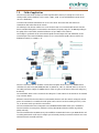
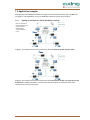
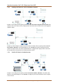
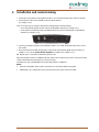
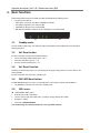
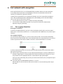
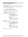
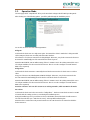
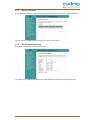
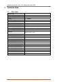
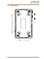
EoC 2-01 Ethernet over Coax | WiFi Operation Instructions Operation Instructions | EoC 2-01 | Ethernet over Coax | WiFi Contents 1. Product description ....................................................................................................................................... 4 1.1. Disposal of wastes ................................................................................................................................ 4 1.2. Scope of delivery................................................................................................................................... 4 1.3. Field of application ............................................................................................................................... 5 1.4. Connections, indications, operating elements ...................................................................................... 6 1.5. Application examples ........................................................................................................................... 7 1.5.1. Feeding in of IP data in a SAT-IF distribution structure: ............................................................... 7 1.5.2. Feeding in of IP data in a CATV distribution structure: ................................................................ 8 1.5.3. Feed in of IP data in a headend system: ....................................................................................... 8 2. Installation and commissioning .................................................................................................................... 9 3. Basic functions ............................................................................................................................................ 10 3.1. Standby mode: .................................................................................................................................... 10 3.2. EoC Reset button: ............................................................................................................................... 10 3.3. EoC Reset Function: ............................................................................................................................ 10 3.4. WiFi WPS/Reset button: ...................................................................................................................... 10 3.5. WiFi access: ........................................................................................................................................ 10 4. EoC network with encryption ...................................................................................................................... 11 4.1. Pair or group formation: ..................................................................................................................... 11 5. Settings for the WiFi network...................................................................................................................... 12 5.1. Accessing the configuration screen..................................................................................................... 12 5.1.1. Login .......................................................................................................................................... 12 5.2. Operation Mode ................................................................................................................................. 13 5.3. Wireless Settings ................................................................................................................................ 14 5.3.1. Wireless Basic Settings ............................................................................................................... 14 5.3.2. Wireless Security Setup .............................................................................................................. 14 5.3.3. Wireless Site Survey.................................................................................................................... 15 5.3.4. Wireless Advanced Settings........................................................................................................ 15 5.4. Wireless Schedule ............................................................................................................................... 16 5.5. TCP/IP Settings ................................................................................................................................... 16 5.5.1. LAN Interface Setup ................................................................................................................... 16 5.6. Management ...................................................................................................................................... 17 5.6.1. Access Point Status .................................................................................................................... 17 5.6.2. Statistics ..................................................................................................................................... 17 5.6.3. Time Zone Setting ...................................................................................................................... 18 5.6.4. System Log ................................................................................................................................. 18 5.6.5. Upgrade Firmware ...................................................................................................................... 19 5.6.6. Save / Reload Settings ................................................................................................................ 19 5.6.7. Password Setup .......................................................................................................................... 20 6. Troubleshooting .......................................................................................................................................... 21 6.1. LEDs .................................................................................................................................................... 21 7. Technical data ............................................................................................................................................. 22 7.1. Data sheet .......................................................................................................................................... 22 7.2. Drilling template ................................................................................................................................. 23 2 2015-01-1916 | © AXING AG Schweiz | Konstrukions -, Typenänderung, Irrtümer und Druckfehler vorbehalten Safety instructions Do NOT use the device near water or in rooms with high humidity such as humid cellars or near swimming pools. Do NOT use the device outdoors. All connections must be located inside a building. Keep the device away from moisture, dust or corrosive liquids. Do NOT install the device, use it or perform maintenance during a thunderstorm. There is a risk of electric shock during thunderstorm. Connect ONLY appropriate accessories to the device. Make sure that all cables are connected to the correct port. Carefully lay the Ethernet, antenna and electric cables to ensure that nobody can step on or stumble over them. Do NOT cover the ventilation slots of the device since insufficient air supply may result in damage to the device. Do NOT place any objects on the device. Position the device in a place where NOBODY can step on it. Prior to maintenance or dismounting work, disconnect the Ethernet and electric cable from the device. In case of damage, interrupt the power supply. Do NOT try to repair the device. Contact your local retailer to order a new device. Do NOT open the device or unit. Opening the device or removing its covers causes risks, for example due to high voltage. This device should ONLY be repaired or uninstalled by qualified service personnel. For more information, contact your retailer. 2015-01-19 | © AXING AG Schweiz | Konstrukions -, Typenänderung, Irrtümer und Druckfehler vorbehalten 3 Operation Instructions | EoC 2-01 | Ethernet over Coax | WiFi 1. Product description 1.1. Disposal of wastes Your device is marked with the WEEE symbol (Waste Electronics and Electrical Equipment). This means that the electrical and electronic components must not be disposed of as residual waste. Used electrical and electronic components must be disposed of separately. 1.2. Scope of delivery EoC 2-01 1 x EoC 2-01 Ethernet over Coax Modem 1 x Network cable 1.5 m (RJ45) 1 x Power cable with euro plug 1 x CFA 8-00 terminating resistor 1 x Quick Start Guide EoC 2-00 2 x EoC 2-01 Ethernet over Coax Modem 2 x Network cable 1.5 m (RJ45) 2 x Power cable with euro plug 2 x CFA 8-00 terminating resistor 2 x Quick Start Guide Lieferbares Zubehör: 4 IEC connecting cable 1.5…10 m Modem connecting cable 1.5…10 m Adapter F/IEC Adapter F/IEC Combiner BAK 150-80 – 999-80 MAK 150-80 – 999-80 CFA 1-00, IEC socket / F plug CFA 10-00, IEC plug / F plug TZU 40-03 2015-01-1916 | © AXING AG Schweiz | Konstrukions -, Typenänderung, Irrtümer und Druckfehler vorbehalten 1.3. Field of application The EoC 2-01 modem allows feeding in of IP data signals from the Internet, for example via a router in an existing coaxial antenna distributor, such as SAT-IF-, DVB-T, CATV- or head end distribution systems (in the star or tree distribution). Several Eoc 2-01 modems communicates in a Peer-to-Peer mode. This means that each modem can communicate with each modem in the network. The advantage of an ethernet solution over a coax solution is that no new network cables must be laid. The data is transmitted through the low-attenuation return channel, frequency range of 2...68 MHz. Depending on the quality of the coaxial cable, transmission distances of up to 700 m can be realized. The feeding in is performed via the return channel capable terrestrial input of the SAT multiswitch, via the terrestrial input of the antenna distributor structure or via a return channel capable antenna socket in the distribution network (see example 1...5). Internet or other fed IP data are available at return channel capable antenna sockets (e.g. AXING antenna socket BSD 4-xx, BSD 21-xx, BSD 960-00, BSD 961-xx, BSD 963-xx, SSD 2-xx, SSD 4-00, SSD 5-xx, SSD 6-xx or SSD 7-00) (connection examples for AXING antenna sockets are given on the Internet under www.axing.com | Download). Two networkable devices can be connected to the LAN ports of a EoC modem. The IP network can be extended to up to 64 EoC devices. All devices connected to the EoC modems can communicate between each other. Data is exchanged, network games are transmitted or a centralized network printer can be accessed. For the monitoring of houses, rooms etc., an IP camera can be operated via a EoC modem. The EoC 2-01 WiFi modem has an integrated router with WLAN function which allows you to establish an internet connection on smart phones, tablet PCs and any other WLAN end devices without any problems, quickly and easily. The EoC 2-01 WiFi modem as WLAN access point establishes communication between your WLAN devices and an existing LAN network. In this way for example you can instantly extend your network to include even rooms which would not be accessible otherwise. 2015-01-19 | © AXING AG Schweiz | Konstrukions -, Typenänderung, Irrtümer und Druckfehler vorbehalten 5 Operation Instructions | EoC 2-01 | Ethernet over Coax | WiFi 1.4. Connections, indications, operating elements 1 2 3 4 5 6 7 8 9 1. Power ON/OFF 2. LAN, RJ 45 socket 3. WiFi ON/OFF 4. EoC F socket 2-862 MHz (data 2-65 MHz) 5. TV F socket 85-862 MHz 6. EoC Reset button 7. WiFi WPS/Reset button 8. LAN, RJ 45 socket 10 11 12 13 9. Mains socket 110-230 V 10. Power LED 11. EoC LED 12. LAN LED 13. WiFi LED A TV or radio device can be connected to the TV-F socket on the rear side of the EoC modem. The integrated distributor is equipped with a highly selective filter so that the TV/radio reception is not interfered with by the data traffic. If the TV F socket ist not used, the socket has to be terminated with an termination resistor CFA 800! 6 2015-01-1916 | © AXING AG Schweiz | Konstrukions -, Typenänderung, Irrtümer und Druckfehler vorbehalten 1.5. Application examples All components in the distribution structure must support the return channel frequency range 2-68 MHz. This also applies to SAT multiswitches, the passive distribution components and for antenna sockets. 1.5.1. Feeding in of IP data in a SAT-IF distribution structure: If the terrestrial input of the SAT multiswitch is not assigned, it must be terminated with a 75 Ohm terminating resistor. Example 1: The feeding of the IP signal is performed via the return channel capable antenna socket. Example 2: The feeding of the IP signal is performed via the return channel capable terrestrial input of the multiswitch. A combiner TZU 40-03 is used. It prevents that the IP signals are transferred via the return channel into the receive antenna system. 2015-01-19 | © AXING AG Schweiz | Konstrukions -, Typenänderung, Irrtümer und Druckfehler vorbehalten 7 Operation Instructions | EoC 2-01 | Ethernet over Coax | WiFi 1.5.2. Feeding in of IP data in a CATV distribution structure: Example 3: The feeding of the IP signal is performed via the return channel capable antenna socket. If the IP-data are fed via the antenna socket, a high-pass filter TZU 19-65 must be installed in the coaxial supply line (amplifier output). Example 4: IP data feeding for exactly one antenna socket: The feeding of the IP signal is performed via the EoC combiner TZU 40-03. The integrated high pass of 85-1006 MHz prevents the transmission of the IP signal in the CATV network. The antenna socket BSD 963-13 is equipped with a high pass filter on the trunk. The IP signal will not be transferred to the following antenna sockets. 1.5.3. Feed in of IP data in a headend system: Example 5: The feeding of the IP signal is performed via the EoC combiner TZU 40-03. The combiner TZU 40-03 has an integrated high pass of 85-1006 MHz. The high pass prevents the transmission of the IP signals to the head end. 8 2015-01-1916 | © AXING AG Schweiz | Konstrukions -, Typenänderung, Irrtümer und Druckfehler vorbehalten 2. Installation and commissioning 1. Connect the router with the enclosed Ethernet cable to one of both RJ-45 LAN sockets of the EoC modem. 1. Connect the EoC socket to the available antenna network structure (see example 1 to 4). There are several ways to feed the IP data into the existing antenna network structure. – via a return channel capable antenna socket in the distribution network (see example 1 or 3) – via the passive terrestrial input of the SAT multiswitch or the passive terrestrial input of a distribution structure (see example 2 or 4). 2. Connect your computer using the enclosed Ethernet cable to one of both RJ-45 LAN sockets of the second EoC modem. 3. Then connect the EoC modem using the EoC-F socket to the return channel capable antenna socket (see example 1 or 3) or to the return channel capable EoC combiner (see example 2 or 4). Repeat step 3 + 4 for further commissioning of EoC 2-01. After all connections have been established, the EoC devices can be switched on by means of the mains switch and the connected devices (PC, laptop etc.) can be booted up. The LEDs Power, EoC, LAN and WiFi are lit and the data transfer is established. Notes: Up to two networkable devices can be connected to one EoC modem without any switch. Additionally, a TV or radio device can be connected to the TV-F socket of the EoC modem. 2015-01-19 | © AXING AG Schweiz | Konstrukions -, Typenänderung, Irrtümer und Druckfehler vorbehalten 9 Operation Instructions | EoC 2-01 | Ethernet over Coax | WiFi 3. Basic functions After having switched on the EoC modem, the LEDs should indicate the following states: The green Power LED is lit. – After approx. 10 seconds, the LEDs are lit/flashing as follows: – EoC LED green (flashes in case of data traffic) – LAN LED green (flashes in case of data traffic) – WiFi LED green (if WiFi is switched on) green (flashing in case of data traffic) 3.1. Standby mode: The EoC modem switches after several minutes without data traffic to the Standby mode. The Power LED is flashing green then. 3.2. EoC Reset button: The EoC reset button is used for the following functions: reset to the factory default setting (press > 10 s). delete the network key (press 5…8 s) generate a private network (press <1 s) 3.3. EoC Reset Function: Hold the reset button depressed for one second using a bent up paper clip, in order to reset the device to the factory defaults. The EoC reset button does not work in standby mode. 3.4. WiFi WPS/Reset button: The WiFi WPS/Reset button is used to reset the WiFi router to the factory IP address 192.168.100.111 The WiFi WPS/reset button does not work in standby mode. 3.5. WiFi access: Switch WiFi ON. WiFi is active: Network name (SSID) = EoCxxxxxx (xxxxxx = last six signs of the MAC adress, you find on the type label of the modem) Encryption = WPA2 Password = 0000000000000000 You should change the default password to secure your WiFi network! 10 2015-01-1916 | © AXING AG Schweiz | Konstrukions -, Typenänderung, Irrtümer und Druckfehler vorbehalten 4. EoC network with encryption An EoC network consists of two or several (maximum 64) EoC modems which use the same network key. In an existing antenna system with several participants, all devices can communicate with each other. Therefore, you should create a private EoC network. Securing your EoC network allows you to protect the information sent via the network from unauthorized access. This is particularly important in multi-family homes, office buildings, schools and other buildings. There are two ways to secure your EoC network. Use the EoC Reset button to generate a random network key automatically. You can use the Security software to specify a key for your EoC network (free download under http://www.axing.com | Download). 4.1. Pair or group formation: Deleting the network key: To generate an invidual network key, you have to delete the default network key first. Press the EoC Reset button on the rear side of the EoC device for 5…8 seconds (until the Power LED flashes). Carry out this step for all devices. Pair and group formation: Press the EoC Reset button briefly (<1 s) on the rear side of the EoC device. The Power LED starts flashing. Now also press the EoC Reset button of the next EoC modem briefly. A new network key between the two EoC modems is generated and the devices establish a connection. The EoC LED will flash for a short time. In order to connect the two devices to each other, press the EoC Reset button on the second device within a time period of two minutes. Check the LEDs on both EoC devices. The Power LEDs must flash during the connection establishment of the devices. Wait for approx. one minute while the EoC devices get connected to each other. As soon as the procedure has been completed, both Power- and EoC LEDs are again permanently lit. If the Power LED is not flashing, after you have pressed the EoC Reset button, then you might have kept it pressed for too long. Try it again and press the WiFi WPS/Reset button for <1 second. If the EoC LEDs are not lit on both EoC devices, the EoC devices are not connected. Repeat the steps in this section. 2015-01-19 | © AXING AG Schweiz | Konstrukions -, Typenänderung, Irrtümer und Druckfehler vorbehalten 11 Operation Instructions | EoC 2-01 | Ethernet over Coax | WiFi 5. Settings for the WiFi network The EoC 2-01 WiFi modem is configured using a web browser. The factory IP address is 192.168.100.111 and the subnet mask is 255.255.255.0. The WiFi WPS/Reset button is used to reset the WiFi router to the factory IP address 192.168.100.111. Press the WiFi WPS/Reset button and keep it pressed for at least 10 seconds. Then switch off the device and switch it on again. The device is now in the delivery state again. 5.1. Accessing the configuration screen Change the IP address of the PC / laptop, for example to 192.168.100.11: Control panel > Network connections > LAN connection >Properties > Internet protocol version 4 TCP/IPv4 > Properties > Use the following IP address: Press OK to save. Connect the EoC 2-01 using a LAN patch cable to the PC / laptop. Now enter the IP address 192.168.100.111 in the web browser. A dialog for user name and password input is displayed. 5.1.1. Login The configuration screen of the EoC 2-01 is protected by a password. Enter the user name admin and then the ex-factory preset password 000000 Click Ok. The Wireless AP router window is opened. 12 2015-01-1916 | © AXING AG Schweiz | Konstrukions -, Typenänderung, Irrtümer und Druckfehler vorbehalten 5.2. Operation Mode The main page, called "Setup Wizard" offers you the most basic settings needed for Wi-Fi operating mode. After selecting one of the following options, you will be guided through the installation process. You are able to choose one of the following functions: Bridge AP In this mode the device acts as a single access point. The network the device is attached to is being extended via the LAN ports (device acts as switch) and via the Wi-Fi interface. If EoC feature is used, the EoC network is also being bridged. This means, every device connected to the EoC 201 network is automatically part of the network the EoC-device is part of. Attention: NAT disabled, same IP-Address-Range, if there is a DHCP-Server in the existing network, this Server also assigns IP-Addresses in the network of the EoC 2-01. There is no need to configure a network-internal DHCP-Server separately. Bridge Client In this mode the device connects to a manually selected wireless Access Point. The device acts as a wireless client. Every port of the EoC 2-01, including LAN and Wi-Fi is bridged. This means, every device connected to the EoC 2-01 network is automatically part of the wireless network the device is connected to. Attention: NAT disabled, same IP-Address-Range, if there is a DHCP-Server in the existing network, this Server also assigns IP-Addresses in the network of the EoC 2-01. There is no need to configure a network-internal DHCP-Server separately. Attention: The EoC 2-01 is not able to connect to existing networks, which use WPA in this mode. AP & Client In this mode the device acts in the same mode as "Bridge Client" - but the EoC 2-01 device creates its own WiFi network with the settings you have to enter during the installation process. During the installation process you will have to select to which Wi-Fi network the device should connect to. The web-front-end offers you a "Wireless Site Survey" at that specific installation point. Attention: Please note that the newly created network uses the same channel as the network to which the device connects to. 2015-01-19 | © AXING AG Schweiz | Konstrukions -, Typenänderung, Irrtümer und Druckfehler vorbehalten 13 Operation Instructions | EoC 2-01 | Ethernet over Coax | WiFi 5.3. Wireless Settings 5.3.1. Wireless Basic Settings On this page the settings for the local Wi-Fi Access Point are set. Attention: Only 2.4 GHz-Mode is supported! In the "Mode" menu you can select whether you want the device to act as "AP" (Access Point), "Client" (of another Wi-Fi-Network) or "AP + WDS". 5.3.2. Wireless Security Setup On this page the settings for Wireless Security are set. Please note that only WPA & WPA2 are secure options (WEP is known to be vulnerable). The use of WPA2-AES (no mixed mode) is recommended. The key has to consist of at least 8 characters. You are free to choose of capital and small letters as well as digits. 14 2015-01-1916 | © AXING AG Schweiz | Konstrukions -, Typenänderung, Irrtümer und Druckfehler vorbehalten 5.3.3. Wireless Site Survey Before applying the settings you have to decide to which Wi-Fi network you want the EoC 2-01 to connect to. You can rescan the available networks using the "Site Survey" button on top. 5.3.4. Wireless Advanced Settings Very specific advanced Wi-Fi settings can be set here. For example you can adjust the RF Output Power, which directly correlates with the Wi-Fi coverage range. 2015-01-19 | © AXING AG Schweiz | Konstrukions -, Typenänderung, Irrtümer und Druckfehler vorbehalten 15 Operation Instructions | EoC 2-01 | Ethernet over Coax | WiFi 5.3.5. Wireless Schedule The Wireless Schedule allows the user to set times at which the Wi-Fi broadcast is being deactivated. You can for instance choose to disable Wi-Fi at night. This feature is disabled by default. 5.4. TCP/IP Settings 5.4.1. LAN Interface Setup On this page the IP Address and Subnet Mask of the local EoC 2-01 device is being set. 16 2015-01-1916 | © AXING AG Schweiz | Konstrukions -, Typenänderung, Irrtümer und Druckfehler vorbehalten 5.5. Management 5.5.1. Access Point Status The status page shows some basically information about the system, Wi-Fi Connection and LAN Connection. 5.5.2. Statistics This page gives you an overview about sent / received packets inside the specific networks. 2015-01-19 | © AXING AG Schweiz | Konstrukions -, Typenänderung, Irrtümer und Druckfehler vorbehalten 17 Operation Instructions | EoC 2-01 | Ethernet over Coax | WiFi 5.5.3. Time Zone Setting Time, Date and Time-zone can be adjusted here. Optionally a NTP (Network Time Protocol) Server can be added here, too. 5.5.4. System Log On this page you can view the current system log. Also you can specify a log server to upload the logs to. 18 2015-01-1916 | © AXING AG Schweiz | Konstrukions -, Typenänderung, Irrtümer und Druckfehler vorbehalten 5.5.5. Upgrade Firmware This page enables you to upload new released firmware versions. In case of an update you receive a document with additional information about how to update the device. In some cases it is necessary to clear your browser-cache after you upgraded your firmware. Updates are published on our website: http://www.axing.com/. 5.5.6. Save / Reload Settings At this page you can export the current configuration into a file to download onto your local computer. Also it is possible to restore these settings or load factory defaults. 2015-01-19 | © AXING AG Schweiz | Konstrukions -, Typenänderung, Irrtümer und Druckfehler vorbehalten 19 Operation Instructions | EoC 2-01 | Ethernet over Coax | WiFi 5.5.7. Password Setup This page allows you to customize the used password for accessing the web-front-end. The default credentials are: User: 'admin' Password: '000000' 20 2015-01-1916 | © AXING AG Schweiz | Konstrukions -, Typenänderung, Irrtümer und Druckfehler vorbehalten 6. Troubleshooting 6.1. LEDs The LEDs indicate an "activity" and are used for troubleshooting. Power LED off Make sure that the network cable is connected correctly. Make sure that the mains switch of the EoC modem is switched on. LAN LED is not flashing No data traffic. Check the following: Are the router and the modem switched on? Is the Ethernet cable connected firmly to the LAN port of the router/modem? Can the PC - connected to the router - establish a connection to the Internet? Press the EoC Reset button on each EoC modem for 10 seconds to restore the factory settings of the EoC modem. If necessary generate a new network key (see chapter 4 on page 12). EoC LED off - is not lit The EoC devices cannot be found. Make sure that the EoC devices are connected to the same antenna network and that they use the same network key. Position the EoC modem closer to the computer or the EoC modem. After having activated the network security, make sure that all EoC modems use the same network key. If the problem occurs, after the network key has been changed, re-establish the factory settings of each device again. Then, you can generate the key again (see chapter 4 on page 12). Check whether your antenna system provides a return channel. EoC-LED is lit in red The line attenuation between the EoC modem is too high. Position the EoC modem closer to the master device. 2015-01-19 | © AXING AG Schweiz | Konstrukions -, Typenänderung, Irrtümer und Druckfehler vorbehalten 21 Operation Instructions | EoC 2-01 | Ethernet over Coax | WiFi 7. Technical data 7.1. Data sheet Frequency range EoC input/output 2…1006 MHz IP signal 2…68 MHz TV output 85…1006 MHz Through loss <0,5 dB Output level min. 1…30 MHz 100 dBμV Output level min. 30…68 MHz 90 dBμV Network Up to 64 EoC modems Gross data rate 500 Mbps Net data rate 230 Mbps Range up to 700 m Modulation 4096/1024/256/64/16/8-QAM, QPSK, BPSK and ROBO modulation scheme Encryption 128 bit AES Ethernet interface 10/100/1000 Mbps Network standards Home Plug AV IEEE1901, IEEE802.3, IEEE802.3u WiFi network standard IEEE 802.11/b/g/n Frequency range 13 channels 2.412GHz~2.472GHz Connections (TV/EoC) 2 F sockets Connections (LAN) 2 RJ 45 LEDs Power /EoC /LAN/WiFi Switching power supply unit 110-230 V~ 50/60 Hz Power consumption max. 5.5 W Operating temperature 0°C ~ 40°C Dimensions 145 (W) x 82.5 (D) x 33 (H) mm Corresponds to the standards EN 50083-2 Class A 22 2015-01-1916 | © AXING AG Schweiz | Konstrukions -, Typenänderung, Irrtümer und Druckfehler vorbehalten 7.2. Drilling template 90 41 2015-01-19 | © AXING AG Schweiz | Konstrukions -, Typenänderung, Irrtümer und Druckfehler vorbehalten 23 Operation Instructions | EoC 2-01 | Ethernet over Coax | WiFi 24 2015-01-1916 | © AXING AG Schweiz | Konstrukions -, Typenänderung, Irrtümer und Druckfehler vorbehalten