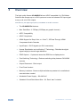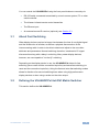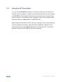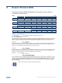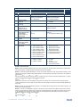
1
K R A ME R E LE CT R O N IC S L TD . USER MANUAL MODEL: VS-66HDCPxl 6x6 DVI Matrix Switcher P/N: 2900-300018 Rev 7 Contents 1 Introduction 1 2 2.1 2.2 2.3 3 3.1 3.2 3.3 4 Getting Started Achieving the Best Performance Safety Instructions Recycling Kramer Products Overview About Fast Switching Defining the VS-66HDCPxl 6x6 DVI Matrix Switcher Using the IR Transmitter Installing in a Rack 2 2 3 3 4 5 5 8 9 5 5.1 5.2 6 6.1 6.2 6.3 6.4 6.5 6.6 6.7 6.8 6.9 6.10 Connecting the VS-66HDCPxl Connecting to the VS-66HDCPxl via RS-232 Connecting via Ethernet Operating the VS-66HDCPxl 6x6 DVI Matrix Switcher Routing Inputs to Outputs Disconnecting the Outputs Storing and Recalling a Setup Changing the Port Switching Speed Setting HDCP to On/Off Acquiring the EDID Locking and Unlocking the Front Panel Resetting the Ethernet Configuration to Default Values Controlling Configuration via the Ethernet Port Firmware Upgrade 10 11 12 13 13 13 14 15 16 16 18 19 19 19 7 Technical Specifications 20 8 Default Communication Parameters 21 9 Kramer Protocol 2000 22 Figures Figure 1: VS-66HDCPxl 6x6 DVI Matrix Switcher Front Panel Figure 2: VS-66HDCPxl 6x6 DVI Matrix Switcher Rear Panel Figure 3: Connecting the VS-66HDCPxl 6x6 DVI Matrix Switcher Figure 4: SELECTOR Buttons 6 7 11 14 VS-66HDCPxl – Contents i 1 Introduction Welcome to Kramer Electronics! Since 1981, Kramer Electronics has been providing a world of unique, creative, and affordable solutions to the vast range of problems that confront the video, audio, presentation, and broadcasting professional on a daily basis. In recent years, we have redesigned and upgraded most of our line, making the best even better! Our 1,000-plus different models now appear in 11 groups that are clearly defined by function: GROUP 1: Distribution Amplifiers; GROUP 2: Switchers and Routers; GROUP 3: Control Systems; GROUP 4: Format/Standards Converters; GROUP 5: Range Extenders and Repeaters; GROUP 6: Specialty AV Products; GROUP 7: Scan Converters and Scalers; GROUP 8: Cables and Connectors; GROUP 9: Room Connectivity; GROUP 10: Accessories and Rack Adapters and GROUP 11: Sierra Products. Congratulations on purchasing your Kramer VS-66HDCPxl 6x6 DVI Matrix Switcher, which is ideal for the following typical applications: Conference room presentations Advertising Rental and staging VS-66HDCPxl - Introduction 1 2 Getting Started We recommend that you: Unpack the equipment carefully and save the original box and packaging materials for possible future shipment i 2.1 Review the contents of this user manual Go to http://www.kramerelectronics.com/support/product_downloads.asp to check for up-to-date user manuals, application programs, and to check if firmware upgrades are available (where appropriate). Achieving the Best Performance To achieve the best performance: Use only good quality connection cables (we recommend Kramer highperformance, high-resolution cables) to avoid interference, deterioration in signal quality due to poor matching, and elevated noise levels (often associated with low quality cables) Do not secure the cables in tight bundles or roll the slack into tight coils Avoid interference from neighboring electrical appliances that may adversely influence signal quality Position your Kramer VS-66HDCPxl away from moisture, excessive sunlight and dust ! 2 This equipment is to be used only inside a building. It may only be connected to other equipment that is installed inside a building. VS-66HDCPxl - Getting Started 2.2 Safety Instructions ! 2.3 Caution: There are no operator serviceable parts inside the unit Warning: Use only the power cord that is supplied with the unit Warning: Do not open the unit. High voltages can cause electrical shock! Servicing by qualified personnel only Warning: Disconnect the power and unplug the unit from the wall before installing Recycling Kramer Products The Waste Electrical and Electronic Equipment (WEEE) Directive 2002/96/EC aims to reduce the amount of WEEE sent for disposal to landfill or incineration by requiring it to be collected and recycled. To comply with the WEEE Directive, Kramer Electronics has made arrangements with the European Advanced Recycling Network (EARN) and will cover any costs of treatment, recycling and recovery of waste Kramer Electronics branded equipment on arrival at the EARN facility. For details of Kramer’s recycling arrangements in your particular country go to our recycling pages at http://www.kramerelectronics.com/support/recycling/. VS-66HDCPxl - Getting Started 3 3 Overview The high quality Kramer VS-66HDCPxl is an HDCP compatible 6 x 6 DVI Matrix Switcher that accepts up to six DVI inputs and routes the selected DVI input signal to any or all of six DVI outputs. Note that only the digital signal (DVI D) is available on the DVI connector. The VS-66HDCPxl features: Max. Data Rate - 6.75Gbps (2.25Gbps per graphic channel) HDTV Compatibility HDCP Compliance HDMI Support for Deep Color, x.v.Color™, 3D Pass-Through, HDMI Compressed Audio Channels Input/Output - DVI-D signals (on DVI-I connectors) Kramer Equalization and re-Klocking™ Technology - Rebuilds the digital signal integrity to travel longer distances EDID Capture - Copies and stores the EDID from a display device Fast Switching Technology - Reduces switching delay between DVI/HDMI sources Output Disconnect - Each output Front Panel Lockout Memory Locations - Stores multiple switches as presets to be recalled and executed when needed 4 Worldwide Power Supply - 100-240V AC Standard 19-inch Rack Mount Size - 2U. Rack “ears” included VS-66HDCPxl - Overview You can control the VS-66HDCPxl using the front panel buttons or remotely via: RS-232 serial commands transmitted by a touch screen system, PC or other serial controller 3.1 The Kramer infrared remote control transmitter The Ethernet port An external remote IR receiver (optional), see Section 3.3 About Fast Switching Older display devices required a longer time between the loss of one digital signal and the introduction of another, as well as a physical disconnection of the interconnecting cable in order to be able to detect and adjust to the new video attributes and parameters. Normal switching, therefore, introduced a 5V signal disconnection along with a delay in switching. Many newer display devices, however, are now capable of “on-the-fly” switching. Depending on the display device in use, the VS-66HDCPxl allows for fast switching (minor reset and the connection kept alive) and extra fast switching (no reset and the connection kept alive). Using the fast and extra fast switching modes allows for fraction-of-a-second switching times when using high performance display devices or when using a scaler on the video output. 3.2 Defining the VS-66HDCPxl 6x6 DVI Matrix Switcher This section defines the VS-66HDCPxl. VS-66HDCPxl - Overview 5 6 Figure 1: VS-66HDCPxl 6x6 DVI Matrix Switcher Front Panel VS-66HDCPxl – Overview # Feature Function 1 IR Receiver and LED IR remote control sensor. LED lights yellow when receiving an IR signal 2 POWER LED Lights green when the unit is turned on 3 ALL Button Press to select all inputs or all outputs (see Section 6.1) 4 OFF Button Press to disconnect one or all outputs (see Section 6.2) 5 SELECT OUT Buttons Press to select an output (from 1 to 6) 6 SELECT IN Buttons Press to select an input (from 1 to 6) 7 STO Button Press to store a switching configuration 8 RCL Button Press to recall a switching configuration 9 LOCK Button Press and hold to lock the front panel buttons and to acquire the EDID (see Section 6.7). Press and hold a second time to unlock the front panel buttons 10 EDID Button Press to acquire the EDID 11 OUTPUT 1 to 6 Indicates the output channels and their respective input selections on the 7-segment display 12 INPUT 7-segment Display Number shown on the display indicates the relevant input channel VS-66HDCPxl – Overview Figure 2: VS-66HDCPxl 6x6 DVI Matrix Switcher Rear Panel # Feature Function 13 INPUT DVI Connectors Connect to the DVI sources (from 1 to 6) 14 OUTPUT DVI Connectors Connect to the DVI acceptors (from 1 to 6) 15 RS-232 9-pin D-sub (F) Connector Connects to a PC or the serial remote controller (see Section 8) 16 ETHERNET RJ-45 Connector Connects to a PC or other Ethernet controller via a LAN (see Section 8) 17 RESET Button Press and hold to reset the Ethernet configuration to its factory default values (see Section 8) 18 REMOTE IR 3.5mm Mini Jack Connects to an external IR receiver unit for controlling the machine via an IR remote controller (instead of using the front panel IR receiver), see Section 3.3 19 Mains Power Connector with Switch and Fuse Connects to the AC mains supply and switches the unit on or off 7 3.3 Using the IR Transmitter You can use the RC-IR3 IR transmitter to control the machine via the built-in IR receiver on the front panel or, instead, via an optional external IR receiver (Model: C-A35M/IRR-50). The external IR receiver can be located up to 15 meters away from the machine. This distance can be extended to up to 60 meters when used with three extension cables (Model: C-A35M/A35F-50). Before using the external IR receiver, be sure to arrange for your Kramer dealer to insert the internal IR connection cable (P/N: 505-70434010-S) with the 3.5mm connector that fits into the REMOTE IR opening on the rear panel. Connect the external IR receiver to the REMOTE IR 3.5mm connector. 8 VS-66HDCPxl - Overview 4 Installing in a Rack This section provides instructions for rack mounting the unit. VS-66HDCPxl - Installing in a Rack 9 5 Connecting the VS-66HDCPxl i Always switch off the power to each device before connecting it to your VS-66HDCPxl. After connecting your VS-66HDCPxl, connect its power and then switch on the power to each device. To connect the VS-66HDCPxl as illustrated in the example in Figure 3: 1. Connect up to six DVI sources (for example, computer graphics sources) to the IN DVI connectors. 2. Connect the OUT DVI connectors to up to six DVI acceptors (for example, DVI displays). 3. If required, connect a PC and/or controller to the RS-232 port (see Section 5.1) and/or the Ethernet port (see Section 5.1). 4. Connect the device to the mains electricity (not shown in Figure 3). 5. Power the device. 6. If required, acquire the EDID (see Section 6.6). 10 VS-66HDCPxl - Connecting the VS-66HDCPxl Figure 3: Connecting the VS-66HDCPxl 6x6 DVI Matrix Switcher 5.1 Connecting to the VS-66HDCPxl via RS-232 You can connect to the VS-66HDCPxl via an RS-232 connection using, for example, a PC. Note that a null-modem adapter/connection is not required. To connect to the VS-66HDCPxl via RS-232: Connect the RS-232 9-pin D-sub rear panel port on the VS-66HDCPxl unit via a 9-wire straight cable (only pin 2 to pin 2, pin 3 to pin 3, and pin 5 to pin 5 need to be connected) to the RS-232 9-pin D-sub port on your PC VS-66HDCPxl - Connecting the VS-66HDCPxl 11 5.2 Connecting via Ethernet You can connect to the VS-66HDCPxl via Ethernet using either of the following methods: Directly to the PC using a crossover cable (see Section 5.2.1) Via a network hub, switch, or router, using a straight-through cable (see Section 5.2.2) After connecting the VS-66HDCPxl to the Ethernet port, configure your local Ethernet port by following the instructions in the Kramer Ethernet Configuration User Guide available from http://www.kramerelectronics.com/support/product_downloads.asp. Note: If you want to connect via a router and your IT system is based on IPv6, speak to your IT department for specific installation instructions. 5.2.1 Connecting the Ethernet Port Directly to a PC You can connect the Ethernet port of the VS-66HDCPxl directly to the Ethernet port on your PC using a crossover cable with RJ-45 connectors. i 5.2.2 This type of connection is recommended for identifying the VS66HDCPxl with the factory configured default IP address. Connecting the Ethernet Port via a Network Hub or Switch You can connect the Ethernet port of the VS-66HDCPxl to the Ethernet port on a network hub or using a straight-through cable with RJ-45 connectors. 12 VS-66HDCPxl - Connecting the VS-66HDCPxl 6 Operating the VS-66HDCPxl 6x6 DVI Matrix Switcher This section describes how to: 6.1 Route inputs to outputs (see Section 6.1) Disconnect outputs (see Section 6.2) Store and recall a setup (see Section 6.3) Change the port switching speed (see Section 6.4) Set HDCP on or off (see Section 6.5) Acquire the EDID (see Section 6.6) Lock and unlock the front panel (see Section 6.7) Reset the Ethernet configuration to default values (see Section 6.8) Control the machine via the Ethernet port (see Section 6.9) Routing Inputs to Outputs To route an input to an output: Press an OUT key, followed by an IN key to route this input to that output To route one input to all outputs: 6.2 Press ALL followed by an IN button. The input is routed to all outputs Disconnecting the Outputs To disconnect one output: Press the OUT button of the output to disconnect and press OFF To disconnect all outputs at once: Press the ALL button and then press OFF. This disconnects all the outputs VS-66HDCPxl - Operating the VS-66HDCPxl 6x6 DVI Matrix Switcher 13 6.3 Storing and Recalling a Setup You can use the STO and RCL buttons to store up to 12 setups and then recall them as illustrated in Figure 4. IN 1 is used for setup number 1 and OUT 1 is used for setup number 7. Figure 4: SELECTOR Buttons i The gray numbers (1 to 12) in Figure 4 that illustrate the corresponding store/recall configuration numbers are for the purpose of illustration only and do not actually appear on the buttons. To store a setup (for example, to preset 10): 1. Configure the switching as required for the preset 2. Press the STO button. The STO button flashes. 3. Select an OUT or IN SELECT button to store the machine setup (for example, OUT 4 for preset 10). 4. Press the STO button to store the current setup. In this example, the OUT 4 button stores the setup. Press the STO button within 10 seconds as the store operation times out automatically after this period. To recall a setup (for example, from preset 10): 1. Press the RCL button. The RCL button flashes. 2. Press the relevant OUT or IN button that stored the setup. In this example, press OUT 4 for preset 10. 3. Press the RCL button to recall the stored setup. 14 VS-66HDCPxl - Operating the VS-66HDCPxl 6x6 DVI Matrix Switcher 6.4 Changing the Port Switching Speed The switching speed can be set per port to any of the following: 3—Normal (default) 2—Fast 1—Extra fast To change the port switching speed: 1. Ensure that the device is in normal switching mode, (that is, not Store, Recall or EDID mode). 2. Press the RCL and EDID buttons at the same time. The RCL and EDID buttons flash, and the display indicates the switching speed mode of each port. IN 1, IN 2 and IN 3 are illuminated (red). 3. Press one or more (or ALL) of the OUT buttons to select the port to change. The selected port setting on the LED display flashes. 4. Press one of the IN 1/IN 2/IN 3 button to toggle the switching speed, (to Extra fast/Fast/Normal, respectively). The switching speed displayed changes for the selected ports. 5. Press the LOCK button to confirm the change. The switching speed for the selected port is changed and the device reverts to the normal switching mode. Note: If the LOCK button is not pressed within about 12 seconds, the device exits the port speed switching mode automatically and all changes are lost. VS-66HDCPxl - Operating the VS-66HDCPxl 6x6 DVI Matrix Switcher 15 6.5 Setting HDCP to On/Off HDCP support can be enabled (On) or disabled (Off) for each of the HDMI inputs, allowing the source to transmit a non-HDCP signal if required (for example, when working with a Mac computer) To set the HDCP: 1. Turn the power off on the machine. 2. Press and hold the IN 1, IN 2 and LOCK buttons simultaneously and turn the power on while pressing these buttons (you will need more than one person to perform this step). The machine is set to the HDCP enable/disable mode. The input front panel buttons’ status indicates the HDCP state of each input: HDCP enabled (ON) on an input – that input button is illuminated HDCP disabled (OFF) on an input – that button is not illuminated 3. Press an input button to change its status. You can press one or more inputs. 4. Once you have changed the status of HDCP on the inputs as desired, press the EDID to save the changes and exit the HDCP enable/disable mode to return to normal operation. Note: If the EDID button is not pressed within about 12 seconds, the device exits the port speed switching mode automatically and all changes are lost. 6.6 Acquiring the EDID You can acquire the EDID from: 16 One output set to one or more of the six inputs (see Section 6.6.1) Different outputs set to different inputs (see Section 6.6.2) The default EDID (see Section 6.6.3) VS-66HDCPxl - Operating the VS-66HDCPxl 6x6 DVI Matrix Switcher 6.6.1 Acquiring an EDID from a Single Connected Output To acquire or change the EDID of a new output display: 1. Connect the required acceptor to the output from which you want to acquire the EDID. 2. Press the EDID and STO buttons simultaneously and hold them for 3 seconds. Both buttons flash. 3. Press the IN SELECT button to which the EDID is to be copied. The selected input number flashes on the display. 4. Select the OUT SELECT button from which the EDID is to be acquired. 5. Press the EDID button. The EDID has been captured when the display returns to normal. 6.6.2 Acquiring an EDID from Several Sets of Inputs and Outputs To acquire the EDID from several sets of inputs and outputs (for example, OUT 1 to IN 1 and OUT 6 to IN 3): 1. Connect the required acceptors to the outputs from which you want to acquire the EDID. 2. Press the EDID and STO buttons simultaneously and hold them for 3 seconds. Both buttons flash. 3. Press the SELECT IN button to which the first EDID is to be copied (for example, IN 1). The selected input number flashes on the display. 4. Press the SELECT OUT button from which the first EDID is to be acquired (for example, OUT 1). 5. Press the SELECT IN 1 button again. The IN 1 button stops flashing. VS-66HDCPxl - Operating the VS-66HDCPxl 6x6 DVI Matrix Switcher 17 6. Press another SELECT IN to which the next EDID is to be copied (for example, IN 3). The selected input number flashes on the display. 7. Press the SELECT OUT button from which the next EDID is to be acquired (for example, OUT 6). 8. Press the SELECT IN 3 button again. The IN 3 button stops flashing. 9. Press the SELECT IN buttons to which you want to copy the EDID (for example, IN 1 and IN 3). 10. Insure that the relevant input numbers flash on the display. 11. Press the EDID button. The process is complete when the display returns to normal. 6.6.3 Acquiring the Default EDID To reset to the default EDID: 1. Press the EDID and STO buttons simultaneously and hold them for 3 seconds. Both buttons flash. 2. Press the SELECT IN button that copies the EDID. The selected input number flashes on the display. 3. Press the OFF button until a "0" (zero) appears on the display. 4. Press the EDID button. The process is complete when the display returns to normal. 6.7 Locking and Unlocking the Front Panel To prevent unintended tampering with the unit via the front panel buttons, lock your VS-66HDCPxl. To lock the VS-66HDCPxl: 18 Press the PANEL LOCK button on the front VS-66HDCPxl - Operating the VS-66HDCPxl 6x6 DVI Matrix Switcher 6.8 Resetting the Ethernet Configuration to Default Values i This procedure resets only the IP related parameters. All switching and preset values remain unchanged. To reset the IP parameters to their default values (see Section 8): Press and hold the ETH Reset button on the rear panel while powering up the device 6.9 Controlling Configuration via the Ethernet Port To control several units via Ethernet, connect the Master unit (Machine # 1) Ethernet port on your PC. Use your PC to configure the initial settings (see Section 5.1). 6.10 Firmware Upgrade Instructions for upgrading the firmware can be found in the STC Firmware Upgrade document. VS-66HDCPxl - Operating the VS-66HDCPxl 6x6 DVI Matrix Switcher 19 7 Technical Specifications INPUTS: 6 DVI connectors OUTPUTS: 6 DVI connectors MAX. DATA RATE: 6.75Gbps (2.25Gbps per graphic channel) COMPLIANCE WITH STANDARDS: Supports DVI and HDCP MAX RESOLUTION: Up to UXGA; 1080p POWER CONSUMPTION: 100240VAC; 50/60Hz, 38VA CONTROLS: Front panel buttons, infrared remote control transmitter, RS-232, Ethernet OPERATING TEMPERATURE: 0° to +40°C (32° to 104°F) STORAGE TEMPERATURE: -40° to +70°C (-40° to 158°F) HUMIDITY: 10% to 90%, RHL non-condensing DIMENSIONS: 19" x 9.3" x 2U W, D, H WEIGHT: 2.5kg (5.5lbs) approx. INCLUDED ACCESSORIES: Power cord, IR transmitter, rack “ears” OPTIONS: External remote IR receiver cable Specifications are subject to change without notice at http://www.kramerelectronics.com 20 VS-66HDCPxl - Technical Specifications 8 Default Communication Parameters RS-232 Protocol 2000 Baud Rate: 9600 Data Bits: 8 Stop Bits: 1 Parity: None Command Format: HEX Example (Output 1 to Input 1): 0x01, 0x81, 0x81, 0x81 Ethernet IP Address: 192.168.1.39 TCP Port: 5000 UDP Port 50000 Subnet Mask: 255.255.255.0 VS-66HDCPxl - Default Communication Parameters 21 9 Kramer Protocol 2000 The Kramer Protocol 2000 RS-232/RS-485 communication uses four bytes of information as defined below. MSB LSB DESTINATION D 6 N5 5 N4 4 1 7 2nd byte I6 6 I5 5 I4 4 1 7 3rd byte O6 6 O5 5 O4 4 1 7 4th byte OVR 6 X 5 M4 4 0 7 1st byte INSTRUCTION N3 3 N2 2 N1 1 N0 0 INPUT I3 3 I2 2 I1 1 I0 0 OUTPUT O3 3 O2 2 O1 1 O0 0 MACHINE NUMBER M2 M1 2 1 M0 0 M3 3 1st BYTE: Bit 7 – Defined as 0. D – “DESTINATION”: 0 - for sending information to the switchers (from the PC); 1 - for sending to the PC (from the switcher). N5…N0 – “INSTRUCTION” The function that is to be performed by the switcher(s) is defined by the INSTRUCTION (6 bits). Similarly, if a function is performed via the machine’s keyboard, then these bits are set with the INSTRUCTION NO., which was performed. The instruction codes are defined according to the table below (INSTRUCTION NO. is the value to be set for N5…N0). Bit 7 – Defined as 1. I6…I0 – “INPUT”. When switching (ie. instruction codes 1 and 2), the INPUT (7 bits) is set as the input number which is to be switched. Similarly, if switching is done via the machine’s front-panel, then these bits are set with the INPUT NUMBER which was switched. For other operations, these bits are defined according to the table. 2nd BYTE: Bit 7 – Defined as 1. O6…O0 – “OUTPUT”. When switching (ie. instruction codes 1 and 2), the OUTPUT (7 bits) is set as the output number which is to be switched. Similarly, if switching is done via the machine’s front-panel, then these bits are set with the OUTPUT NUMBER which was switched. For other operations, these bits are defined according to the table. 3rd BYTE: Bit 7 – Defined as 1. Bit 5 – Don’t care. OVR – Machine number override. M4…M0 – MACHINE NUMBER. Used to address machines in a system via their machine numbers. When several machines are controlled from a single serial port, they are usually configured together with each machine having an individual machine number. If the OVR bit is set, then all machine numbers accept (implement) the command, and the addressed machine replies. For a single machine controlled via the serial port, always set M4…M0 = 1, and make sure that the machine itself is configured as MACHINE NUMBER = 1. 4th BYTE: i 22 All the values in the table are decimal, unless otherwise stated VS-66HDCPxl - Kramer Protocol 2000 Instruction Codes for Protocol 2000 Instruction Definition for Specific Instruction # Description Input Output Notes 0 RESET VIDEO 0 0 1 1 SWITCH VIDEO Set equal to video input which is to be switched (0 = disconnect) Set equal to video output which is to be switched (0 = to all the outputs) 2, 15 3 STORE VIDEO STATUS Set as SETUP # 0 - to store 1 - to delete 2, 3, 15 4 RECALL VIDEO STATUS Set as SETUP # 0 2, 3, 15 5 REQUEST STATUS OF A VIDEO OUTPUT Set as SETUP # Equal to output number whose status is required 4, 3 15 REQUEST WHETHER SETUP IS DEFINED / VALID INPUT IS DETECTED SETUP # or Input # 0 - for checking if setup is defined 1 - for checking if input is valid 8 30 LOCK FRONT PANEL 0 - Panel unlocked 1 - Panel locked 0 2 31 REQUEST WHETHER PANEL IS LOCKED 0 0 16 61 IDENTIFY MACHINE 1 - video machine name 2 - audio machine name 3 - video software version 4 - audio software version 5 - RS422 controller name 6 - RS422 controller version 7 - remote control name 8 - remote software version 9 - Protocol 2000 revision 0 - Request first 4 digits 1 - Request first suffix 2 - Request second suffix 3 - Request third suffix 10 - Request first prefix 11 - Request second prefix 12 - Request third prefix 13 62 DEFINE MACHINE 1 - number of inputs 2 - number of outputs 3 - number of setups 1 - for video 2 - for audio 3 - for SDI 4 - for remote panel 5 - for RS-422 controller 14 NOTES on the above table: NOTE 1 - When the master switcher is reset, (e.g. when it is turned on), the reset code is sent to the PC. If this code is sent to the switchers, it resets according to the present power-down settings. NOTE 2 - These are bi-directional definitions. That is, if the switcher receives the code, it performs the instruction; and if the instruction is performed (due to a keystroke operation on the front panel), then these codes are sent. For example, if the HEX code 01 85 88 83 was sent from the PC, then the switcher (machine 3) switches input 5 to output 8. If the user switched input 1 to output 7 via the front panel keypad, then the switcher sends HEX codes: 41 81 87 83 to the PC. When the PC sends one of the commands in this group to the switcher, then, if the instruction is valid, the switcher replies by sending to the PC the same four bytes that it was sent (except for the first byte, where the DESTINATION bit is set high). NOTE 3 - SETUP # 0 is the present setting. SETUP # 1 and higher are the settings saved in the switcher's memory, (i.e. those used for Store and Recall). NOTE 4 - The reply to a "REQUEST" instruction is as follows: the same instruction and INPUT codes as were sent are returned, and the OUTPUT is assigned the value of the requested parameter. The replies to instructions 10 and 11 are as per the definitions in instructions 7 and 8 respectively. For example, if the present status of machine number 5 is breakaway setting, then the reply to the HEX code 0B 80 80 85 would be HEX codes 4B 80 81 85 VS-66HDCPxl - Kramer Protocol 2000 23 NOTE 8 - The reply is as in TYPE 3 above, except that here the OUTPUT is assigned with the value 0 if the setup is not defined / no valid input is detected; or 1 if it is defined / valid input is detected. NOTE 13 - This is a request to identify the switcher/s in the system. If the OUTPUT is set as 0, and the INPUT is set as 1, 2, 5 or 7, the machine sends its name. The reply is the decimal value of the INPUT and OUTPUT. For example, for a 2216, the reply to the request to send the audio machine name would be (HEX codes): 7D 96 90 81 (i.e. 128dec+ 22dec for 2nd byte, and 128dec+ 16dec for 3rd byte). If the request for identification is sent with the INPUT set as 3 or 4, the appropriate machine sends its software version number. Again, the reply would be the decimal value of the INPUT and OUTPUT - the INPUT representing the number in front of the decimal point, and the OUTPUT representing the number after it. For example, for version 3.5, the reply to the request to send the version number would be (HEX codes): 7D 83 85 81 (i.e. 128dec+ 3dec for 2nd byte, 128dec+ 5dec for 3rd byte). If the OUTPUT is set as 1, then the ASCII coding of the lettering following the machine’s name is sent. For example, for the VS-7588YC, the reply to the request to send the first suffix would be (HEX codes): 7D D9 C3 81 (i.e. 128dec+ ASCII for “Y”; 128dec+ ASCII for “C”). NOTE 14 - The number of inputs and outputs refers to the specific machine which is being addressed, not to the system. For example, if six 16X16 matrices are configured to make a 48X32 system (48 inputs, 32 outputs), the reply to the HEX code 3E 82 81 82 (ie. request the number of outputs) would be HEX codes 7E 82 90 82 ie. 16 outputs NOTE 15 – When the OVR bit (4th byte) is set, then the “video” commands have universal meaning. For example, instruction 1 (SWITCH VIDEO) causes all units (including audio, data, etc.) to switch. Similarly, if a machine is in “FOLLOW” mode, it performs any “video” instruction. NOTE 16 - The reply to the “REQUEST WHETHER PANEL IS LOCKED” is as in NOTE 4 above, except that here the OUTPUT is assigned with the value 0 if the panel is unlocked, or 1 if it is locked. 24 VS-66HDCPxl - Kramer Protocol 2000 For the latest information on our products and a list of Kramer distributors, visit our Web site where updates to this user manual may be found. We welcome your questions, comments, and feedback. Web site: www.kramerelectronics.com E-mail: [email protected] ! SAFETY WARNING Disconnect the unit from the power supply before opening and servicing P/N: 2900- 300018 Rev: 7