1
Installation and Assembly:
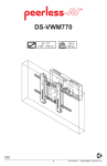
Flat \ Tilt Wall Mount for VESA 400x400
Model: HT642-003
Max Load Capacity: 100 lb (45.4 kg)
3215 W. North Ave. • Melrose Park, IL 60160 • (800) 729-0307 or (708) 865-8870 • Fax: (708) 865-2941 • www.peerlessmounts.com
ISSUED: 07-07-11 SHEET #: 125-9221-1
Note: Read entire instruction sheet before you start installation and assembly.
WARNING
• Do not begin to install your Peerless product until you have read and understood the instructions and warnings
contained in this Installation Sheet. If you have any questions regarding any of the instructions or warnings, please
call Peerless customer service at 1-800-729-0307.
• This product should only be installed by a qualified professional.
• Make sure that the supporting surface will safely support the combined load of the equipment and all attached hardware and components.
• Never exceed the Maximum Load Capacity of 100 lb (45.4 kg).
• If mounting to wood wall studs, make sure that mounting screws are anchored into the center of the studs. Use of
an "edge to edge" stud finder is highly recommended.
• Always use an assistant or mechanical lifting equipment to safely lift and position equipment.
• Tighten screws firmly, but do not overtighten. Overtightening can damage the items, greatly reducing their holding
power.
• This product was designed and intended to be mounted to the following supporting surfaces checked below with
the hardware included in this product as specified in the installation sheet. To mount this product to an alternative
supporting surface, contact Peerless customer care at 1-800-865-2112.
• This product was designed to be installed on the following wall construction only;
WALL CONSTRUCTION
ADDITIONAL HARDWARE REQUIRED
x Wood Stud
None
x Wood Beam
None
x Solid Concrete
None
x Cinder Block
None
x Metal Stud
None
Brick
Contact Customer Service
Other or unsure?
Contact Customer Service
Tools Needed for Assembly
• stud finder ("edge to edge" stud finder is recommended)
• phillips screwdriver
• drill with 1/4" and 5/32" drill bits
• 5/16" socket wrench Table of Contents
Parts List.................................................................................................................................................................................3
Attaching Adapter Bracket to Screen......................................................................................................................................4
Installation to Wood Stud Wall.................................................................................................................................................4
Installation to Solid Concrete and Cinder Block Wall..............................................................................................................5
Installation to Metal Stud.........................................................................................................................................................6
Attaching Mounting Bracket Using Hook On Option...............................................................................................................8
Attaching Mounting Bracket Using Tilt Option.........................................................................................................................9
2 of 8
ISSUED: 07-07-11 SHEET #: 125-9221-1
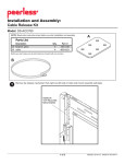
Before you start make sure all parts listed are included with your product.
A
PARTS LIST
Description
A wall plate
B adapter bracket
C 1/4 x 2.5 round phillips screw
D M5 x 12 mm socket pin serrated washer head screw
E #14 x 2.5 wood screw
F 4 mm security allen wrench
G
H
I
J
M8 x 16 mm phillips pan screw
toggler
washer
Alligator® concrete anchor
Qty.
1
1
4
6
6
1
4
4
4
6
Part #
201-1601
201-1931
520-9521
510-1064
5S1-015-C03
560-1129
520-2051
560-9708
540-1008
590-0097
B
Some parts may appear slightly different than illustrated.
C
G
E
D
F
H
I
3 of 8
J
ISSUED: 07-07-11 SHEET #: 125-9221-1
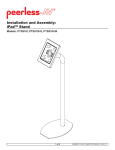
Attaching Adapter Bracket to Screen
1
Attach adapter bracket (B) to back of plasma screen using four M8 x 16 mm phillips screws (G).
Screen
400 mm
400 mm
B
WARNING
• Do not overtighten. Overtightening may cause permanent damage to the screen. Torque to 26-35 in • lb
(30-40 kg • cm).
Installation to Wood Stud Walls
Use a stud finder to locate center of studs.
2 For mounting to 16" centers
Using mounting bracket (A) as a template, drill four 5/32" (4 mm) dia. holes to a minimum depth of 2.5" (64
mm). Attach mounting bracket (A) to centers of wood studs using four #14 x 2.5" wood screws (E) and four
washers (I) as shown below.
A
E
I
4 of 8
ISSUED: 07-07-11 SHEET #: 125-9221-1
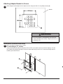
Installation to Solid Concrete and Cinder Block Wall
WARNING
• When installing Peerless wall mounts on cinder block, verify that you have a minimum of 1-3/8" of actual concrete
thickness in the hole to be used for the concrete anchors. Do not drill into mortar joints! Be sure to mount in a solid
part of the block, generally 1" minimum from the side of the block. Cinder block must meet ASTM C-90 specifications. It is suggested that a standard electric drill on slow setting is used to drill the hole instead of a hammer drill to
avoid breaking out the back of the hole when entering a void or cavity.
• Concrete must be 2000 psi density minimum. Lighter density concrete may not hold concrete anchor.
• Make sure that the supporting surface will safely support the combined load of the equipment and all attached hardware and components.
3
Position adapter bracket (A) at desired position on wall.
Use mounting bracket, making sure that it is level, as a
template to mark holes. Drill six 1/4" (6 mm) dia. holes
to a minimum depth of 2-1/2" (64 mm). Concrete must
be 2000 psi density minimum. Insert anchors (J) in holes
flush with wall as shown in figure 5.3. Place wall mount
assembly over anchors and secure with #14 x 2-1/2"
(6 mm x 65 mm) wood screws (E) and washers (I) as
shown in figure 3.4. Make sure wall plate is level and
tighten all fasteners.
WARNING
concrete
surface
1
J
Drill holes and insert anchors (J).
A
2
E
J
I
Place plate (A) over anchors (J) and secure with screws (E) with
washers (I).
• Tighten wood screws firmly, but do not overtighten.
Overtightening can damage the screws, greatly reducing their holding power.
3
• Never tighten in excess of 80 in • lb (9 N.M.).
WARNING
Tighten all fasteners.
• Concrete anchors are not intended for attachment to
concrete wall covered with a layer of plaster, drywall,
or other finishing material as shown below. If mounting to concrete wall covered with plaster/drywall is
unavoidable, plaster/drywall (up to 5/8" thick) must
be counter bored as shown below. Be sure concrete
anchors do not pull away from concrete when tightening screws. If plaster/drywall is thicker than
5/8", custom fasteners must be supplied by installer.
CUTAWAY VIEW
INCORRECT
concrete
wall plate
plaster/
dry wall
SO
LID
CO
NC
RE
J
E
TE
CI
ND
ER
BL
OC
K
I
CORRECT
wall plate
concrete
A
plaster/
dry wall
5 of 8
fig 3.4
ISSUED: 07-07-11 SHEET #: 125-9221-1
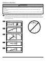
Installation to Metal Stud
WARNING
• Product must be mounted through drywall that has a minimum thickness of 1/2" and into metal studs, 26 gauge or
heavier.
• Make sure that the wall will safely support the combined load of the equipment and all attached hardware and
components.
• Make sure that togglers are anchored into the center of the stud. The use of an "edge to edge" stud finder is highly
recommended.
3
3-1
Using a stud finder, locate and mark the edges of the metal stud used in mounting this product. Use of an edge
to edge stud finder is highly recommended. Use a level to draw a level, vertical line down the center of the stud.
Level wall plate, and mark the center of the four mounting holes. Make sure that the mounting holes are on the stud
center line. Drill four 1/2" holes through drywall and metal studs. Note: It may be necessary to drill 5/32" pilot holes
prior to drilling 1/2" holes.
fig. 1.3
1
drill
1/2"
hole
H
Pivot end of toggler (H).
3-2
2
H
Push into hole.
3-3
3
H
Rotate toggler (H) clockwise to wedge it
against inside walls of metal stud.
3-4
4
H
Slide plastic cap forward while pulling back
firmly on ring.
3-5
5
H
Break off excess.
6 of 8
ISSUED: 07-07-11 SHEET #: 125-9221-1
Attaching Mounting Bracket Using Hook On Option
7
Attach four M5 x 12 mm serrated washer head
socket pin screws (D) to the holes on the sides of
mounting bracket (A) using the 4mm security allen
wrench (F) provided.
7-1 Position slots of adapter brackets (B) onto the
four M5 x 12 mm serrated washer head socket pin
screws (D) attached to mounting bracket (A).
B
D
SLOT
A
D
A
D
7-2 To secure adapter brackets (B) to mounting bracket (A), attach two M5 x 12 mm serrated washer head socket pin
screws (D) into the threaded inserts of adapter brackets (B), and through the slots on the sides of mounting bracket
(A). Tighten with the 4 mm security allen wrench (F).
For tilt option skip to Step 8
D
SLOT
B
D
A
7 of 8
ISSUED: 07-07-11 SHEET #: 125-9221-1
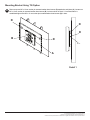
Mounting Bracket Using Tilt Option
8
Remove top two M5 x 12 mm socket pin serrated washer head screws (D) attached to wall plate (A). Loosen two
M5 x 12 mm socket pin serrated washer head screws (D) in slot as shown in Detail 1. Once desired tilt is
established tighten two M5 x 12 mm socket pin serrated washer head screws (D) in slots.
D
D
D
B
D
SLOT
A
Detail 1
8 of 8
ISSUED: 07-07-11 SHEET #: 125-9221-1
© 2010 Peerless Industries, Inc. All rights reserved.
Peerless is a registered trademark of Peerless Industries, Inc.
All other brand and product names are trademarks or registered trademarks of their respective owners.