1
Installation and Assembly:
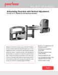
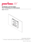
Articulating Swivel Arm for 32" - 60" Large Flat Panel Screens
Model: PLA1-UN7, PLA1-UN7S
Features:
•
•
•
•
•
Universal design supports most 32" to 63" plasma and LCD screens
One-touch adjustable tilt (5° back and 15° forward)
Complete integrated security from the wall to the screen
Up to 6" of horizontal adjustment when the screen is up
Sleek, airy design complements today’s flat panel technologies
R
This product is UL Listed. It must be
installed by a qualified professional
installer.
Max Load Capacity: 150 lb (68 kg)
3215 W. North Ave. • Melrose Park, IL 60160 • (800) 729-0307 or (708) 865-8870 • Fax: (708) 865-2941 • www.peerlessmounts.com
ISSUED: 09-21-04 SHEET #: 201-9269-6 11-29-05
Note: Read entire instruction sheet before you start installation and assembly.
WARNING
• Do not begin to install your Peerless product until you have read and understood the instructions and warnings
contained in this Installation Sheet. If you have any questions regarding any of the instructions or warnings, please
call Peerless customer service at 1-800-729-0307.
• This product should only be installed by a qualified professional.
• Do not attach directly to a metal stud wall. Use of a triple stud WSP wall plate is required for attachment to metal
studs (contact customer care). Metal stud installation is not UL evaluated.
• Make sure that the supporting surface will safely support the combined load of the equipment and all attached hardware and components.
• Never exceed the Maximum UL Load Capacity of 150 lb (68 kg).
• If mounting to wood wall studs, make sure that mounting screws are anchored into the center of the studs. Use of an
"edge to edge" stud finder is highly recommended.
• Always use an assistant or mechanical lifting equipment to safely lift and position equipment.
• Tighten screws firmly, but do not overtighten. Overtightening can damage the items, greatly reducing their holding
power.
Tools Needed for Assembly
•
•
•
•
•
•
•
•
•
Phillips screwdriver
5/32" or 4 mm drill bit (for installation to wood stud wall)
1/4" or 6 mm drill bit (for installation to concrete wall)
10 mm wrench
Hammer
Tape
3/4" open end wrench (optional: for roll adjustment)
6 mm allen wrench (included)
stud finder ("edge to edge" stud finder is recommended)
Table of Contents
Parts List .......................................................................................................................................................................... 3, 4
Installation to Double Wood Stud Wall .................................................................................................................................. 5
Installation to Solid Concrete or Cinder Block ....................................................................................................................... 6
Installing Swing Arm to Wall Bracket and Assembling Components to Arm ......................................................................... 7
Assembling Adapter Bracket ........................................................................................................................................... 8-10
Installing Adapter Bracket to Screen ................................................................................................................................... 11
Installing Pitch Roll Assembly to Adapter Bracket .............................................................................................................. 12
Optional: Placing Screen in Vertical Position ..................................................................................................................... 12
Installing Screen to Articulating Swivel Mount ..................................................................................................................... 13
Final Adjustment to Screen ................................................................................................................................................ 14
For customer care call (800) 729-0307 or (708) 865-8870.
2 of 14
ISSUED: 09-21-04 SHEET #: 201-9269-6 11-29-05
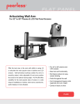
Before you begin, make sure all parts shown are included with your product.
Parts List
PLA1-UN7 PLA1-UN7S
Qty Part #
Part #
2 200-1388 200-4388
A
Description
c-channel spacer
B
vertical bracket
2
200-1446
200-4446
C
adapter plate
1
200-1300
200-4300
D
c-channel
2
200-1331
200-4331
E
.34" x .75" x .25" spacer
4
540-1002
540-1002
F
M4 x 10 mm serrated head socket pin screw
8
520-1156
520-1156
G
10-32 x 1/2" socket pin screw
4
520-1055
520-1055
H
M5 x 12 mm socket pin screw
8
520-1064
520-1064
I
M6 x 12 mm socket pin screw
8
520-1050
520-1050
J
K
L
M
N
O
P
Q
R
S
T
U
V
W
X
Y
Z
AA
M8 x 15 mm socket pin screw
M8 x 25 mm socket pin screw
1/4" SAE washer
10-32 x 3/8" serrated head socket pin screw
.38" x .625" x .5" spacer
#10 SAE washer
M5 x 30 mm socket pin screw
.219" x .5" x .5" nylon spacer
M4 x 30 mm serrated head socket pin screw
.25" x .5" x .625" nylon spacer
M8 x 40 mm socket pin screw
M5 x 8 mm socket pin screw
M5 x 16 mm socket pin screw
.281" x .5" x .375" spacer
M6 x 20 mm serrated head socket pin screw
4 mm security allen wrench
M5 x 40 mm serrated head socket pin screw
.25" x .5" x 1.25" H aluminum spacer
6
4
8
4
6
8
4
4
4
4
6
4
8
4
4
1
6
6
520-1068
520-1101
540-9440
520-1151
540-1015
540-9400
520-1112
590-1096
510-1090
590-1106
520-1152
520-1062
520-1161
540-9416
510-9554
560-9646
510-1001
580-1067
520-1068
520-1101
540-9440
520-1151
540-1015
540-9400
520-1112
590-1096
510-1090
590-1106
520-1152
520-1062
520-1161
540-9416
510-9554
560-9646
510-1001
580-1067
F
G
H
U
I
V
J
M
X
A
C
B
D
K
E
P
R
L
T
N
Y
Z
AA
O
3 of 14
Q
S
W
ISSUED: 09-21-04 SHEET #: 201-9269-6 11-29-05
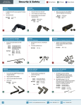
Parts List
BB
CC
DD
EE
FF
GG
HH
II
JJ
KK
LL
MM
NN
OO
PP
QQ
RR
Description
wall bracket
rotation box
wall support arm axle
tilt pivot retainer assembly
swing arm assembly
pitch roll assembly
#14 phillips wood screw
carriage bolt 3/8"-16 x 3"
M10 x 1.5 x 15 mm screw bolt
10-32 x 1/2" phillips screw
knob
cable clips
snap ring
holding pin
3/4" x 3/16" x 14" bumper strip
3/4" x 3/16" x 10" bumper strip
cable ties
Qty.
1
1
1
1
1
1
8
1
8
2
1
4
1
1
1
2
4
PLA1-UN7
Part #
200-1472
200-1434
200-1052
200-1877
200-0878
200-0288
5S1-015-C03
520-1001
520-9262
520-9509
590-1087
590-1166
560-9641
5M9-025-X02
570-1030
570-1029
560-9711
PLA1-UN7S
Part #
200-4472
200-4434
200-1052
200-4877
200-0879
200-0277
5S1-015-C03
520-1001
520-9262
520-9509
590-1087
590-1166
560-9641
5M9-025-X02
570-1030
570-1029
560-9711
BB
CC
RR
GG
MM
DD
FF
EE
PP
QQ
JJ
KK
LL
NN
II
HH
4 of 14
OO
ISSUED: 09-21-04 SHEET #: 201-9269-6 11-29-05
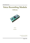
1
Attach adhesive bumper strip (PP) to wall bracket (BB). Next attach one adhesive bumper strip (QQ) to each side of
swing arm (FF).
Note: Be sure swing arm is in correct position as shown with plastic cap at top.
PP
BB
QQ
FF
QQ
WARNING
• Never mount this product to metal studs without the
required accessory.
Installation to Double Wood Stud Wall
2
Using wall bracket (BB) as a template, drill eight
5/32" (4 mm) diameter holes to a minimum depth of
2-1/2" (64 mm) into stud centers. Attach wall
bracket using #14 phillips wood screws (HH) and
phillips screwdriver (not provided).
Skip to step 3, page 7.
HH
WARNING
• Tighten wood screws so that wall bracket is firmly
attached, but do not overtighten. Overtightening can
damage the screws, greatly reducing their holding
power.
BB
• Never tighten in excess of 80 in. • lb (9 N.M.).
• Make sure that mounting screws are anchored into
the center of the studs. The use of an "edge to edge"
stud finder is highly recommended.
5 of 14
ISSUED: 09-21-04 SHEET #: 201-9269-6 11-29-05
Installation to Solid Concrete or Cinder Block
Note: Fasteners for concrete not included, order TWO #ACC 204 accessory kits.
WARNING
• When installing Peerless wall mounts on cinder block, verify that you have a minimum of 1-3/8" of actual concrete
thickness in the hole to be used for the concrete anchors. Do not drill into mortar joints! Be sure to mount in a solid
part of the block, generally 1" minimum from the side of the block. Cinder block must meet ASTM C-90 specifications. It is suggested that a standard electric drill on slow setting is used to drill the hole instead of a hammer drill to
avoid breaking out the back of the hole when entering a void or cavity.
• Concrete must be 2000 psi density minimum. Lighter density concrete may not hold concrete anchor.
• Make sure that the supporting surface will safely support the combined load of the equipment and all attached hardware and components.
2
Use wall bracket (BB), making sure that it is level,
as a template to mark holes. Drill 1/4" (6 mm)
diameter holes to a minimum depth of 2.5" (64 mm).
Insert anchors in holes flush with wall as shown
(right). Place wall bracket over anchors and secure
with #14 x 2.5" (6 mm x 65 mm) wood screws (HH).
Tighten all fasteners.
ACC204
HH
WARNING
• Tighten screws so that wall bracket is firmly attached,
but do not overtighten. Overtightening can damage
the screws, greatly reducing their holding power.
BB
• Never tighten in excess of 80 in. • lb (9 N.M.).
• Make sure that mounting screws are anchored into
the center of the studs. The use of an "edge to edge"
stud finder is highly recommended.
1
CONCRETE
WALL
WARNING
ACC204
• Always attach concrete expansion anchors directly to
load-bearing concrete.
Drill holes and insert anchors.
• Never attach concrete expansion anchors to concrete
covered with plaster, drywall, or other finishing material.
2
BB
ACC204
CUTAWAY VIEW
INCORRECT
Place wall bracket (BB) over anchors and secure with screws.
CORRECT
concrete
BB
plaster/
dry wall
3
concrete
BB
ACC204
plaster/
drywall
Tighten all fasteners.
6 of 14
ISSUED: 09-21-04 SHEET #: 201-9269-6 11-29-05
Installing Swing Arm to Wall Bracket and Assembling Components to Arm
WARNING
• Failure to correctly mount swing arm with plastic cap at top as shown in detail 4 will result in product failure.
• Improperly installed snap ring will result in product failure.
• If you are uncertain that product is properly installed, call customer service.
3
3-1
Note: There are five mounting positions. The center position is shown below.
Insert holding pin (OO) into wall support arm axle (DD). Insert axle through wall bracket (BB) and lower swing arm
(FF). Lock axle in place with holding pin.
3-1 1
Next thread snap ring (NN) into groove at bottom of axle (DD)
protruding wall bracket (BB) as shown.
groove
SNAP RING INSTALLATION: Pull snap ring apart. Wind it around
the tube while feeding it into the groove. Finish by snapping the end
of the snap ring into groove.
OO
DETAIL 4
Note: Fit of axle into
wall bracket and lower
swing arm will be tight.
Gently tap into place
with a hammer if
necessary.
DD
OO
DD
NN
plastic cap
2
FF
BB
groove
FF
NN
NN
4
3
Place rotation box (CC) with threaded holes up over swing arm (FF).
4-1
Insert tilt pivot retainer assembly (EE) through rotation box (CC) and swing arm (FF). Align holes in tilt pivot retainer
assembly with holes in rotation box and secure with two phillips screws (KK) as shown.
4-2
Snap four cable management clips (MM) into swing arms (FF) as shown. Cable ties (RR) are used with clips (MM) for
cord management.
4-1
KK
EE
EE
MM
FF
THREADED
HOLES
FF
RR
FF
CC
Note: Fit of rotation box
into tube will be tight.
Gently tap into place with
a hammer if necessary.
4-2
CC
7 of 14
ISSUED: 09-21-04 SHEET #: 201-9269-6 11-29-05
Use the tables on accompanying screen compatibility chart to assemble the adapter bracket. First, find your screen brand
and model in the tables on accompanying screen compatibility chart. Find the configuration letter which corresponds to
your screen. This letter will be used to determine the proper method of assembly for the adapter bracket. Continue to the
table on the last page of accompanying screen compatibility chart.
Example: For a Sony model KDL-42XBR950 42" screen, use configuration C.
Assembling Adapter Bracket
5
Attach c-channels (D) to adapter plate (C).
Note: Make sure that the holes in the c-channels are facing the proper direction. See figures 1 and 2.
C
D
TOP C-CHANNEL (D) HOLES
FACING UPWARD
fig. 1
D
TOP C-CHANNEL (D) HOLES
FACING DOWNWARD
fig. 2
Fasten c-channels (D) to adapter plate (C) using four 10-32 x 1/2" socket pin screws (G).
G
D
D
C
8 of 14
ISSUED: 09-21-04 SHEET #: 201-9269-6 11-29-05
6
Slide vertical brackets (B) onto c-channels (D) as shown below. Refer to the table on accompanying screen
compatibility chart to determine the proper assembly of the adapter bracket. For standard bracket mounting, see
figure 3. For reverse bracket mounting, see figure 4.
Example: For a Sony model KDL-42XBR950 42" screen, assemble the bracket as shown in figure 4 below (reverse
bracket mounting).
B
D
B
fig. 3
Bracket Mounting: Standard
D
fig. 4
Bracket Mounting: Reverse
9 of 14
ISSUED: 09-21-04 SHEET #: 201-9269-6 11-29-05
7
Place the screen on the floor face down. Set a cloth on the floor to prevent scratching the screen. If the screen
has knobs on the back, remove them. Place adapter bracket on the center of the screen. Slide the vertical
brackets (B) along the c-channels (D) of the adapter bracket until the slots on the back of the vertical brackets
are aligned to the holes on the back of the screen. Fasten vertical brackets to c-channels using four 10-32 x 3/8"
serrated head socket pin screws (M).
Note: Do not fully tighten the screws to allow the adapter bracket to slide along the vertical brackets freely.
B
D
C
M
B
10 of 14
ISSUED: 09-21-04 SHEET #: 201-9269-6 11-29-05
Installing Adapter Bracket to Screen
8
Slide the vertical brackets (B) along the c-channels (D) of the adapter bracket until the slots on the back of the
vertical brackets are aligned to the holes on the back of the screen. Fully tighten the four 10-32 x 3/8" screws (M)
which hold the vertical brackets to the c-channels. Refer to the table on the last page of accompanying screen
compatibility chart to determine the proper fasteners to use. Attach the assembled adapter bracket to the back of
the screen using screws, upper and lower spacers as pictured. Verify that all holes are properly aligned, then use a
phillips screwdriver to tighten the screws.
Note: See figure 5 below for slot sizes.
Example: For a Sony model KDL-42XBR950 42" screen, attach the plate to the screen using screws (F or H) and
upper spacers (O) through the small slots on the vertical brackets. Lower spacers are not required for this
configuration.
M
B
SCREWS
UPPER
SPACERS
D
LOWER
SPACERS
fig. 5
Mounting Slots
SMALL SLOTS ARE USED
FOR M4 AND M5 SCREWS.
LARGE SLOTS ARE USED
FOR M6 AND M8 SCREWS.
MOUNTING SLOTS: SMALL
MOUNTING SLOTS: LARGE
11 of 14
ISSUED: 09-21-04 SHEET #: 201-9269-6 11-29-05
Installing Pitch Roll Assembly to Adapter Bracket
9
Insert and tape carriage bolt (II) into top hole of pitch
roll assembly (GG). Attach pitch roll assembly to
adapter plate (C) with four M10 socket screws (JJ).
Tighten M10 socket screws with 6 mm allen
wrench (Y).
C
II
GG
JJ
OPTIONAL:
Placing Screen in Vertical Position
DO NOT REMOVE M5 SCREWS. For vertical orientation,
unscrew two M5 screws until screw is able to move freely
in slot of tilt bracket as shown in figures 16A & 16B. Hold
adapter bracket stationary and rotate tilt bracket 90° by
hand or using a lever (example: wood 2" x 4"). Align M5
screws with threaded holes on bracket and tighten two M5
screws back into bracket.
TILT BRACKET
M5 SCREWS
CENTER
BOLT
CAUTION
BRACKET
• Do not overtighten screws. Overtightening may
hinder roll option.
ADAPTER
BRACKET
CARRIAGE BOLT
VERTICAL
POSITION
HORIZONTAL
POSITION
GENERIC ADAPTER BRACKET
TILT BRACKET
WASHER
BRACKET
BRACKET
M5 SCREW
SLOT
CENTER
BOLT
RETAINING
SPACER
THREADED
HOLE
M5 SCREW
WASHER
M5 SCREW
RETAINING
SPACER
SLOT
Fig. 16A
12 of 14
Fig. 16B
ISSUED: 09-21-04 SHEET #: 201-9269-6 11-29-05
Installing Screen to Articulating Swivel Mount
WARNING
• Always use an assistant or mechanical lifting equipment to safely lift and position the plasma television.
10
Insert two M10 screws (JJ) into rotation box (CC)
as shown. Leave approximately 1/4" of exposed
thread.
CC
B
.25"
1/4"
10-1 Hook pitch roll assembly (GG) onto M10 screws
(JJ). Insert carriage bolt (II) into slot of tilt pivot
retainer assembly (EE) as shown. Install tilt
adjustment knob (LL).
JJ
EE
LL
GG II
JJ
10-1
10-2 Install remaining two M10 screws (JJ). HAND
TIGHTEN all four M10 screws to allow for tilt
adjustment. Remove tape from carriage bolt (II).
For tilt adjustment, gently push back on the top of
screen to relieve pressure on knob. Adjust tilt to
desired position and tighten tilt adjustment knob
(LL), then securely tighten all four M10 screws
using 6 mm allen wrench (Y).
GG
II
LL
As a final precaution, check all fasteners and
tighten securely.
JJ
10-2
13 of 14
ISSUED: 09-21-04 SHEET #: 201-9269-6 11-29-05
Final Adjustments to Screen
11
Depending on the specific size and weight of the screen, the articulating swing arm may be angled at
different positions, causing the screen to appear to lean sideways at different articulating positions. The
pitch roll assembly (GG) allows the screen to be manually adjusted to appear horizontal at all times. To
adjust, gently rotate the screen by hand to the desired position.
ARTICULATING ARM
SCREEN
Note: Center bolt is factory torqued for optimal performance to adjust for range of screen sizes.
If it is too difficult to adjust roll of screen, torque may be adjusted by following the procedures below.
11-1 Adjust tilt adjustment knob (LL) to allow maximum tilt.
11-2 Insert 3/4" open-end wrench (not provided) into side of pitch roll assembly (GG) and rotate center bolt
counterclockwise to loosen torque.
Note: Do not loosen or tighten more than 1/8 turn.
GG
GG
LL
CC
CENTER
BOLT
CENTER
BOLT
SCREEN
WRENCH
11-1
11-2
14 of 14
© 2005 Peerless Industries, Inc. All rights reserved.
Peerless is a registered trademark of Peerless Industries, Inc.
All other brand and product names are trademarks or registered trademarks of their respective owners.
ISSUED: 09-21-04 SHEET #: 201-9269-6 11-29-05