1
3600
Modem User’s Guide
Trademarks
Any trademarks mentioned in this manual are acknowledged to be the
property of the trademark owners.
ii
Modem 3600
5HJXODWRU\,QIRUPDWLRQ
)&&5HTXLUHPHQWV
7KLVHTXLSPHQWFRPSOLHVZLWK)&&UXOHV3DUW/RFDWHGRQWKH
HTXLSPHQWLVWKH)&&5HJLVWUDWLRQ1XPEHUDQG5LQJHU(TXLYDOHQFH
1XPEHU5(1<RXPXVWSURYLGHWKLVLQIRUPDWLRQWRWKHWHOHSKRQH
FRPSDQ\LIUHTXHVWHG
7KH5HJLVWUDWLRQ1XPEHUDQG5(1LVLQVFULEHGRQWKHSULQWHGFLUFXLW
ERDUGRQLQVHUWFDUGVRURQDODEHODWWDFKHGWRHLWKHUWKHFKDVVLVERWWRP
RUPHWDOHQGSODWHRQVWDQGDORQHRUUDFNPRGHOV7KH)&&UHTXLUHVWKDW
WKHVHQXPEHUVEHSURPLQHQWO\GLVSOD\HGRQDQRXWVLGHVXUIDFHRIWKH
HTXLSPHQW
7KH5(1LVXVHGWRGHWHUPLQHWKHQXPEHURIGHYLFHV\RXPD\OHJDOO\
FRQQHFWWR\RXUWHOHSKRQHOLQH,QPRVWDUHDVWKHVXPRIWKH5(1RIDOO
GHYLFHVFRQQHFWHGWRRQHOLQHPXVWQRWH[FHHGILYH&RQWDFW\RXU
WHOHSKRQHFRPSDQ\WRGHWHUPLQHWKHPD[LPXP5(1IRU\RXUFDOOLQJ
DUHD
$YDULHW\RI8QLYHUVDO6HUYLFH2UGHULQJ&RGH862&WHOHSKRQHZDOO
MDFNVDUHDYDLODEOHIRUGLIIHUHQWW\SHVRIGHYLFHVRUVHUYLFHV7KH862&
MDFNUHTXLUHGIRUWKLVXQLWLV5-5-6-0
7KHWHOHSKRQHFRPSDQ\PD\FKDQJHWHFKQLFDORSHUDWLRQVRUSURFHGXUHV
DIIHFWLQJ\RXUHTXLSPHQW<RXZLOOEHQRWLILHGRIFKDQJHVLQDGYDQFHWR
JLYH\RXDPSOHWLPHWRPDLQWDLQXQLQWHUUXSWHGWHOHSKRQHVHUYLFH
,I\RXH[SHULHQFHWURXEOHZLWKWKLVWHOHSKRQHHTXLSPHQWSOHDVHFRQWDFW
Black Box
at 724-746-5500
IRULQIRUPDWLRQRQREWDLQLQJVHUYLFHRUUHSDLUV7KHWHOHSKRQHFRPSDQ\
PD\DVNWKDW\RXGLVFRQQHFWWKLVHTXLSPHQWIURPWKHQHWZRUNXQWLOWKH
SUREOHPKDVEHHQUHVROYHG,I\RXUHTXLSPHQWFRQWLQXHVWRGLVUXSWWKH
QHWZRUNWKHWHOHSKRQHFRPSDQ\PD\WHPSRUDULO\GLVFRQQHFWVHUYLFH,I
WKLVRFFXUV\RXZLOOEHLQIRUPHGRI\RXUULJKWWRILOHDFRPSODLQWZLWK
WKH)&&
0RGHP
LLL
5HJXODWRU\,QIRUPDWLRQ
7KLVHTXLSPHQWPD\QRWEHXVHGRQFRLQVHUYLFHSURYLGHGE\WKH
WHOHSKRQHFRPSDQ\&RQQHFWLRQWRSDUW\OLQHVLVVXEMHFWWRVWDWHWDULIIV
$Q)&&FRPSOLDQWWHOHSKRQHFRUGDQGPRGXODUSOXJDUHSURYLGHGZLWK
WKLVHTXLSPHQWZKLFKLVGHVLJQHGWRFRQQHFWWRWKHWHOHSKRQHQHWZRUN
RUSUHPLVHVZLULQJXVLQJDFRPSDWLEOHPRGXODUMDFNWKDWLV3DUW
FRPSOLDQW6HHLQVWDOODWLRQLQVWUXFWLRQVLQ&KDSWHU,QVWDOODWLRQIRU
GHWDLOV
)&&)D[%UDQGLQJ5HTXLUHPHQWV
7KH7HOHSKRQH&RQVXPHU3URWHFWLRQ$FWRIPDNHVLWXQODZIXOIRU
DQ\SHUVRQWRXVHDFRPSXWHURURWKHUHOHFWURQLFGHYLFHWRVHQGDQ\
PHVVDJHYLDDWHOHSKRQHID[PDFKLQHRUPRGHPXQOHVVVXFKPHVVDJH
FOHDUO\FRQWDLQVLQDPDUJLQDWWKHWRSRUERWWRPRIHDFKWUDQVPLWWHG
SDJHRURQWKHILUVWSDJHRIWKHWUDQVPLVVLRQWKHGDWHDQGWLPHLWLVVHQW
DQGDQLGHQWLILFDWLRQRIWKHEXVLQHVVRURWKHUHQWLW\RURWKHULQGLYLGXDO
VHQGLQJWKHPHVVDJHDQGWKHWHOHSKRQHQXPEHURIWKHVHQGLQJPDFKLQH
RUVXFKEXVLQHVVRWKHUHQWLW\RULQGLYLGXDO
3URJUDPPLQJRIWKLVLQIRUPDWLRQLVDIXQFWLRQRIWKHID[VRIWZDUHZKLFK
UXQVRQ\RXUFRPSXWHU,QRUGHUWRSURJUDPWKLVLQIRUPDWLRQSOHDVH
FRQVXOWWKHGRFXPHQWDWLRQSURYLGHGZLWK\RXUID[VRIWZDUH
)&&3DUW'HFODUDWLRQ2I&RQIRUPLW\
)25+20(252)),&(86(
0RGHO1DPH0RGHP9$&YHUVLRQRQO\
&DXWLRQ
7KLVHTXLSPHQWXVHVJHQHUDWHVDQGFDQUDGLDWHUDGLR
IUHTXHQF\HQHUJ\LQWHUIHULQJZLWKUDGLRFRPPXQLFDWLRQV
LIQRWLQVWDOOHGDQGXVHGDFFRUGLQJWRWKHLQVWUXFWLRQ
PDQXDO,WKDVEHHQWHVWHGDQGFRPSOLHVZLWKWKHOLPLWV
IRUD&ODVV%FRPSXWLQJGHYLFHDFFRUGLQJWR)&&5XOHV
3DUW2SHUDWLRQRIWKLVHTXLSPHQWLQDUHVLGHQWLDODUHD
PD\FDXVHLQWHUIHUHQFH,ILWGRHV\RXPXVWFRUUHFWWKH
FDXVHRIWKHLQWHUIHUHQFH
&KDQJHVRUPRGLILFDWLRQVWRWKLVXQLWQRWH[SUHVVO\DSSURYHGE\WKH
SDUW\UHVSRQVLEOHIRUFRPSOLDQFHFRXOGYRLGWKHXVHU
VDXWKRULW\WR
RSHUDWHWKHHTXLSPHQW
LY
0RGHP
5HJXODWRU\,QIRUPDWLRQ
6KLHOGHG&DEOHV
7KLVSURGXFWKDVEHHQWHVWHGDQGFRPSOLHVZLWK)&&OLPLWVIRUD&ODVV%
FRPSXWLQJGHYLFH7HVWLQJZDVGRQHZLWKVKLHOGHGFRPSXWHUFDEOHV
8VLQJXQVKLHOGHGFDEOHVFRXOGFDXVH\RXUV\VWHPWRHPLWH[FHVVUDGLR
IUHTXHQF\LQFUHDVLQJWKHFKDQFHRILQWHUIHUHQFH7RFRPSO\ZLWK)&&
UHJXODWLRQVLWLVQHFHVVDU\WRXVHVKLHOGHGFRPSXWHUFDEOHVZLWK\RXU
LQVWDOODWLRQ
)252)),&(86(21/<
0RGHO1DPH0RGHPDOORWKHUYHUVLRQV
&DXWLRQ
7KLVHTXLSPHQWXVHVJHQHUDWHVDQGFDQUDGLDWHUDGLR
IUHTXHQF\HQHUJ\LQWHUIHULQJZLWKUDGLRFRPPXQLFDWLRQV
LIQRWLQVWDOOHGDQGXVHGDFFRUGLQJWRWKHLQVWUXFWLRQ
PDQXDO,WKDVEHHQWHVWHGDQGFRPSOLHVZLWKWKHOLPLWV
IRUD&ODVV$FRPSXWLQJGHYLFHDFFRUGLQJWR)&&5XOHV
3DUW2SHUDWLRQRIWKLVHTXLSPHQWLQDUHVLGHQWLDODUHD
PD\FDXVHLQWHUIHUHQFH,ILWGRHV\RXPXVWFRUUHFWWKH
FDXVHRIWKHLQWHUIHUHQFH
&KDQJHVRUPRGLILFDWLRQVWRWKLVXQLWQRWH[SUHVVO\DSSURYHGE\WKH
SDUW\UHVSRQVLEOHIRUFRPSOLDQFHFRXOGYRLGWKHXVHU
VDXWKRULW\WR
RSHUDWHWKHHTXLSPHQW
6KLHOGHG&DEOHV
7KLVSURGXFWKDVEHHQWHVWHGDQGFRPSOLHVZLWK)&&OLPLWVIRUD&ODVV$
FRPSXWLQJGHYLFH7HVWLQJZDVGRQHZLWKVKLHOGHGFRPSXWHUFDEOHV
8VLQJXQVKLHOGHGFDEOHVFRXOGFDXVH\RXUV\VWHPWRHPLWH[FHVVUDGLR
IUHTXHQF\LQFUHDVLQJWKHFKDQFHRILQWHUIHUHQFH7RFRPSO\ZLWK)&&
UHJXODWLRQVLWLVQHFHVVDU\WRXVHVKLHOGHGFRPSXWHUFDEOHVZLWK\RXU
LQVWDOODWLRQ
0RGHP
Y
5HJXODWRU\,QIRUPDWLRQ
6SHFLDO5HTXLUHPHQWV)RU&DQDGD
&HUWDLQUHTXLUHPHQWVH[LVWIRUGDWDFRPPXQLFDWLRQSURGXFWV
PDQXIDFWXUHGIRUXVHLQ&DQDGD3ULQFLSOHDPRQJWKHVHUHTXLUHPHQWVLV
WKHDSSOLFDWLRQRIWKH,&ODEHODVGHVFULEHGEHORZ+RZHYHUFHUWDLQGDWD
FRPPXQLFDWLRQSURGXFWVGRQRWUHTXLUHWKH,&ODEHOQRUDGKHUHQFHWR,&
UHTXLUHPHQWV,IWKLVLVWKHFDVHWKH,&ODEHOZLOOQRWEHDIIL[HGWRWKH
XQLWV
,QGXVWU\&DQDGD,&5HTXLUHPHQWV
,&ODEHOVDUHDIIL[HGWRHDFKXQLWVROGLQ&DQDGD7KLVODEHOKDVWKH
FHUWLILFDWLRQQXPEHUIRUWKDWSDUWLFXODUXQLW7KHQXPEHUVDUHGLIIHUHQW
IRUHDFKPRGHO
7KH,QGXVWU\&DQDGDODEHOLGHQWLILHVFHUWLILHGHTXLSPHQW7KLV
FHUWLILFDWLRQPHDQVWKDWWKHHTXLSPHQWPHHWVFHUWDLQ
WHOHFRPPXQLFDWLRQVQHWZRUNSURWHFWLYHRSHUDWLRQDODQGVDIHW\
UHTXLUHPHQWV,&GRHVQRWJXDUDQWHHWKHHTXLSPHQWZLOORSHUDWHWRWKH
XVHU
VVDWLVIDFWLRQ
%HIRUHLQVWDOOLQJWKLVHTXLSPHQWXVHUVVKRXOGHQVXUHWKDWLWLV
SHUPLVVLEOHWREHFRQQHFWHGWRWKHIDFLOLWLHVRIWKHORFDO
WHOHFRPPXQLFDWLRQVFRPSDQ\7KHHTXLSPHQWPXVWDOVREHLQVWDOOHG
XVLQJDQDFFHSWDEOHPHWKRGRIFRQQHFWLRQ,QVRPHFDVHVWKHFRPSDQ\
V
LQVLGHZLULQJDVVRFLDWHGZLWKDVLQJOHOLQHLQGLYLGXDOVHUYLFHPD\EH
H[WHQGHGE\PHDQVRIDFHUWLILHGFRQQHFWRUDVVHPEO\WHOHSKRQH
H[WHQVLRQFRUG7KHFXVWRPHUVKRXOGEHDZDUHWKDWFRPSOLDQFHZLWKWKH
DERYHFRQGLWLRQVPD\QRWSUHYHQWGHJUDGDWLRQRIVHUYLFHLQVRPH
VLWXDWLRQV
5HSDLUVWRFHUWLILHGHTXLSPHQWVKRXOGEHPDGHE\DQDXWKRUL]HG
&DQDGLDQPDLQWHQDQFHIDFLOLW\GHVLJQDWHGE\WKHVXSSOLHU$Q\UHSDLUV
RUDOWHUDWLRQVPDGHE\WKHXVHUWRWKLVHTXLSPHQWRUHTXLSPHQW
PDOIXQFWLRQVPD\JLYHWKHWHOHFRPPXQLFDWLRQVFRPSDQ\FDXVHWR
UHTXHVWWKHXVHUWRGLVFRQQHFWWKHHTXLSPHQW)RUWKHLURZQSURWHFWLRQ
XVHUVVKRXOGHQVXUHWKDWWKHHOHFWULFDOJURXQGFRQQHFWLRQVRIWKHSRZHU
XWLOLW\WHOHSKRQHOLQHVDQGLQWHUQDOPHWDOOLFZDWHUSLSHV\VWHPLI
SUHVHQWDUHFRQQHFWHGWRJHWKHU7KLVSUHFDXWLRQPD\EHSDUWLFXODUO\
LPSRUWDQWLQUXUDODUHDV
YL
0RGHP
5HJXODWRU\,QIRUPDWLRQ
&DXWLRQ8VHUVVKRXOGQRWDWWHPSWWRPDNHLQVWDOODWLRQFRQQHFWLRQV
WKHPVHOYHVEXWVKRXOGFRQWDFWWKHDSSURSULDWHHOHFWULFLQVSHFWLRQ
DXWKRULW\RUHOHFWULFLDQ
5LQJHU(TXLYDOHQFH1XPEHU
7KH5LQJHU(TXLYDOHQFH1XPEHU5(1DVVLJQHGWRHDFKWHUPLQDO
GHYLFHSURYLGHVDQLQGLFDWLRQRIWKHPD[LPXPQXPEHURIWHUPLQDOV
DOORZHGWREHFRQQHFWHGWRDWHOHSKRQHLQWHUIDFH7KHWHUPLQDWLRQRQDQ
LQWHUIDFHPD\FRQVLVWRIDQ\FRPELQDWLRQRIGHYLFHVVXEMHFWRQO\WRWKH
UHTXLUHPHQWWKDWWKHVXPRIWKH5LQJHU(TXLYDOHQFH1XPEHUVRIDOOWKH
GHYLFHVGRHVQRWH[FHHGILYH
&$1$',$1(0,66,215(48,5(0(1760RGHP
9DF
7KLV&ODVV%GLJLWDODSSDUDWXVPHHWVDOOUHTXLUHPHQWVRIWKH&DQDGLDQ
,QWHUIHUHQFH&DXVLQJ(TXLSPHQW5HJXODWLRQV
&HWDSSDUHLOQXPpULTXHGHODFODVVH%UHVSHFWHWRXWHVOHVH[LJHQFHVGX
5qJOHPHQWVXUOHPDWpULHOEURXLOOHXUGX&DQDGD
&$1$',$1(0,66,215(48,5(0(1760RGHPRWKHU
YHUVLRQV
7KLV&ODVV$GLJLWDODSSDUDWXVPHHWVDOOUHTXLUHPHQWVRIWKH&DQDGLDQ
,QWHUIHUHQFH&DXVLQJ(TXLSPHQW5HJXODWLRQV
&HWDSSDUHLOQXPpULTXHGHODFODVVH$UHVSHFWHWRXWHVOHVH[LJHQFHVGX
5qJOHPHQWVXUOHPDWpULHOEURXLOOHXUGX&DQDGD
0RGHP
YLL
5HJXODWRU\,QIRUPDWLRQ
1RUPDV1RUPDV2ILFLDOHV0H[LFDQDV120
(OHFWULFDO6DIHW\6WDWHPHQW
,16758&&,21(6'(6(*85,'$'
7RGDVODVLQVWUXFFLRQHVGHVHJXULGDG\RSHUDFLyQGHEHUiQVHU
OHtGDVDQWHVGHTXHHODSDUDWRHOpFWULFRVHDRSHUDGR
/DVLQVWUXFFLRQHVGHVHJXULGDG\RSHUDFLyQGHEHUiQVHU
JXDUGDGDVSDUDUHIHUHQFLDIXWXUD
7RGDVODVDGYHUWHQFLDVHQHODSDUDWRHOpFWULFR\HQVXV
LQVWUXFFLRQHVGHRSHUDFLyQGHEHQVHUUHVSHWDGDV
7RGDVODVLQVWUXFFLRQHVGHRSHUDFLyQ\XVRGHEHQVHUVHJXLGDV
(ODSDUDWRHOpFWULFRQRGHEHUiVHUXVDGRFHUFDGHODJXD±SRU
HMHPSORFHUFDGHODWLQDGHEDxRODYDERVyWDQRPRMDGRRFHUFD
GHXQDDOEHUFDHWF
(ODSDUDWRHOpFWULFRGHEHVHUXVDGR~QLFDPHQWHFRQFDUULWRVR
SHGHVWDOHVTXHVHDQUHFRPHQGDGRVSRUHOIDEULFDQWH
(OSDUDWRHOpFWULFRGHEHVHUPRQWDGRDODSDUHGRDOWHFKRVyOR
FRPRVHDUHFRPHQGDGRSRUHOIDEULFDQWH
6HUYLFLR±(OXVXDULRQRGHEHLQWHQWDUGDUVHUYLFLRDOHTXLSR
HOpFWULFRPiVDOOiDORGHVFULWRHQODVLQVWUXFFLRQHVGHRSHUDFLyQ
7RGRRWURVHUYLFLRGHEHUiVHUUHIHULGRDSHUVRQDOGHVHUYLFLR
FDOLILFDGR
(ODSDUDWRHOpFWULFRGHEHVHUVLWXDGRGHWDOPDQHUDTXHVX
SRVLFLyQQRLQWHUILHUDVXXVR/DFRORFDFLyQGHODSDUDWRHOpFWULFR
VREUHXQDFDPDVRIiDOIRPEUDRVXSHUILFLHVLPLODUSXHGH
EORTXHDODYHQWLODFLyQQRVHGHEHFRORFDUHQOLEUHURVRJDELQHWHV
TXHLPSLGDQHOIOXMRGHDLUHSRUORVRULILFLRVGHYHQWLODFLyQ
(OHTXLSRHOpFWULFRGHEHUVHUVLWXDGRIXHUDGHODOFDQFHGHIXHQWHV
GHFDORUFRPRUDGLDGRUHVUHJLVWURVGHFDORUHVWXIDVXRWURV
DSDUDWRVLQFOX\HQGRDPSOLILFDGRUHVTXHSURGXFHQFDORU
(ODSDUDWRHOpFWULFRGHEHUiVHUFRQQHFWDGRDXQDIXHQWHGHSRGHU
VyORGHOWLSRGHVFULWRHQHOLQVWUXFWLYRGHRSHUDFLyQRFRPRVH
LQGLTXHHQHODSDUDWR
3UHFDXFLyQGHEHVHUWRPDGDGHWDOPDQHUDTXHODWLHUUDILVLFD\OD
SRODUL]DFLyQGHOHTXLSRQRVHDHOLPLQDGD
YLLL
0RGHP
5HJXODWRU\,QIRUPDWLRQ
/RVFDEOHVGHODIXHQWHGHSRGHUGHEHQVHUJXLDGRVGHWDOPDQHUD
TXHQRVHDQSLVDGRVQLSHOOL]FDGRVSRUREMHWRVFRORFDGRVVREUHR
FRQWUDHOORVSRQLHQGRSDUWLFXODUDWHQFLyQDORVFRQWDFWRV\
UHFHSW FXORVGRQGHVDOHQGHODSDUDWR
(OHTXLSRHOpFWULFRGHEHVHUOLPSLDGR~QLFDPHQWHGHDFXHUGRD
ODVUHFRPHQGDFLRQHVGHOIDEULFDQWH
(QFDVRGHH[LVWLUXQDDQWHQDH[WHUQDGHEHUiVHUORFDOL]DGDOHMRV
GHODVOLQHDVGHHQHUJLD
(OFDEOHGHFRUULHQWHGHEHUiVHUGHVFRQHFWDGRGHOFXDQGRHO
HTXLSRQRVHDXVDGRSRUXQODUJRSHULRGRGHWLHPSR
&XLGDGRGHEHVHUWRPDGRGHWDOPDQHUDTXHREMHFWRVOLTXLGRVQR
VHDQGHUUDPDGRVVREUHODFXELHUWDXRULILFLRVGHYHQWLODFLyQ
6HUYLFLRSRUSHUVRQDOFDOLILFDGRGHEHUiVHUSURYLVWRFXDQGR
D (OFDEOHGHSRGHURHOFRQWDFWRKDVLGRGDxDGRX
E 2EMHFWRVKDQFDtGRROtTXLGRKDVLGRGHUUDPDGRGHQWURGHO
DSDUDWRR
F (ODSDUDWRKDVLGRH[SXHVWRDODOOXYLDR
G (ODSDUDWRSDUHFHQRRSHUDUQRUPDOPHQWHRPXHVWUDXQ
FDPELRHQVXGHVHPSHxRR
H (ODSDUDWRKDVLGRWLUDGRRVXFXELHUWDKDVLGRGDxDGD
0RGHP
L[
5HJXODWRU\,QIRUPDWLRQ
[
0RGHP
&RQWHQWV
5HJXODWRU\,QIRUPDWLRQ
&KDSWHU,QWURGXFWLRQ
6KHOI0RXQW8QLWV )HDWXUHV 'DWD0RGH )D[0RGH 6RIWZDUH &RPPXQLFDWLRQV6RIWZDUH &ODVV)D[&RPPXQLFDWLRQV6RIWZDUH ,QWHUQHW%URZVHU 'HVFULSWLRQ )XQFWLRQDO 3K\VLFDO 0RGHP&DUG &KDSWHU,QVWDOODWLRQ
0RXQWLQJ$FFHVVRULHV (OHFWULFDO,QVWDOODWLRQ $&3RZHU&RQQHFWLRQ '&3RZHU&RQQHFWLRQ '7(&RQQHFWLRQ 7HOHSKRQH/LQH&RQQHFWLRQ 'LDO0RGH3671&RQQHFWLRQ',$/MDFN /HDVHG/LQH&RQQHFWLRQ7(/6(7/($6('/,1(-DFN 6KHOI0RXQW0'&,QVWDOODWLRQ &KDSWHU*HWWLQJ6WDUWHG
2SWLRQ6HOHFWLRQ 3RZHU8S 3ODFLQJD&DOO 'LDOLQJZLWKD6WDQGDUG7HOHSKRQH $XWRGLDOLQJIURP)URQW3DQHO $XWRGLDOLQJIURPD7HUPLQDOZLWKWKH$7&RPPDQGV $QVZHULQJD&DOO $XWRDQVZHULQJ 9
[L
7DEOHRI&RQWHQWV
$QVZHULQJ0DQXDOO\ $QVZHULQJIURP7HUPLQDOZLWK$7&RPPDQG6HW (QGLQJD&DOO (QGLQJD&DOO8VLQJWKH)URQW3DQHO (QGLQJD&DOOIURPD7HUPLQDOZLWKWKH$7&RPPDQG6HW 5HDVRQVIRU&DOO7HUPLQDWLRQ &KDSWHU)URQW3DQHO2SHUDWLRQ
/(''HVFULSWLRQV /&'0HQXV /&'0HQX2SHUDWLRQ )URQW3DQHO6HFXULW\ &KDSWHU$7&RPPDQGV
&RPPDQG&DWHJRULHV 2SHUDWLRQ0RGHV 2IIOLQH&RPPDQG0RGH 2QOLQH&RPPDQG0RGH 'DWD0RGH 6HQGLQJ&RPPDQGVWRWKH0RGHP &UHDWLQJD&RPPDQG6WDWHPHQW$7 $XWREDXG *XLGHOLQHVIRU&UHDWLQJ&RPPDQG6WDWHPHQWV 0RQLWRU'LVSOD\ &RPPDQG6WDWHPHQW%XIIHU %DFNVSDFH.H\ 5HSHDWLQJD&RPPDQG$ 1XPEHUHG&RPPDQGV *URXS&RPPDQGV 5HVSRQVH&RPPDQGV 'LJLW:RUG6HOHFWLRQ9 5HVSRQVH'LVSOD\V4 1HJRWLDWLRQ'LVSOD\V: 3URWRFRO5HVXOW&RGHV?9 &DOO3URJUHVV&RQQHFW6SHHG0HVVDJHV; 1XPEHU&RGH$SSOLFDWLRQ5& 5HVSRQVH1XPEHU&RGHV0HVVDJHV 'LDO&RPPDQGV 'LDOLQJ' 7RQH'LDOLQJ7 3XOVH'LDOLQJ3 ,QVHUW/RQJ3DXVH [LL
9
7DEOHRI&RQWHQWV
:DLWIRU6HFRQG'LDO7RQH: +RRN)ODVK 6ZLWFKLQJWR$QVZHU0RGHDIWHU'LDOLQJ5 5HPDLQLQJLQ&RPPDQG0RGH :DLWIRU6HFRQGVRI6LOHQFH# 'LDOLQJD6WRUHG7HOHSKRQH1XPEHU6Q $XWRGLDO1XPEHU/RFDWLRQ$8Q 9RLFH&DOOV 6ZLWFKLQJIURP9RLFHWR'DWD $QVZHULQJ$&DOO 0DQXDO$QVZHU $7&RPPDQG$QVZHU$ $XWRDQVZHU6 &DOOHU,',' 'LVWLQFWLYH5LQJ'5 7HUPLQDO,QWHUIDFH&RPPDQGV 'DWD&DUULHU'HWHFW& 'DWD6HW5HDG\6 'DWD7HUPLQDO5HDG\' 6HULDO3RUW5LQJ,QGLFDWRU3LQ?5 5HTXHVWWR6HQG&OHDUWR6HQG5 '7(&RQWUROOHG)DOOEDFN5DWH3LQ)% *HQHUDO&RPPDQGV &KDQJLQJIURP'DWD0RGHWR&RPPDQG0RGH /RFDO&KDUDFWHU(FKR( 2QOLQH&KDUDFWHU(FKR) +DQJLQJ8S++ )DVW'LVFRQQHFW++ (3520&KHFN, 6SHDNHU9ROXPH/ 6SHDNHU&RQWURO0 5HWXUQ2QOLQH2 /RQJ6SDFH'LVFRQQHFW< 9ELV*XDUG7RQHV* $V\QFKURQRXV6\QFKURQRXV0RGH6HOHFWLRQ0 0DNH%UHDN'LDO3XOVH5DWLR3 6\QFKURQRXV7UDQVPLW&ORFN6RXUFH; 95DWH6HOHFWLRQ7KUHVKROGV7+ 9$V\PPHWULF%LW5DWHV$6 0RGXODWLRQ00 0D[LPXP'&(6SHHG% 0LQLPXP'&(6SHHG/ $XWR5HWUDLQ( $XWRPDWLF5DWH$GDSWLRQ5 9
[LLL
7DEOHRI&RQWHQWV
0DQXDO5DWH$GDSWLRQ55 3URGXFW5HYLVLRQ/HYHO9 2QOLQH4XLFN5HIHUHQFH+ 3URGXFW6HULDO1XPEHU9 7DON'DWD'$ 9)DVW7UDLQ)7 ,QFRPLQJ&DOO,& /LQH&XUUHQW'LVFRQQHFW/& 'LVDEOH$7&RPPDQG6HW17 'LDO/LQH7UDQVPLW/HYHO7'Q 3ULYDWH/LQH2SHUDWLRQ :LUH2SHUDWLRQ :LUH2SHUDWLRQ 'LDO%DFNXS 'LDO/HDVHG/LQH/ 'LDO%DFNXS'% 5HWXUQWR/HDVHG/LQHIURP'LDO%DFNXS/% 0DQXDO'LDO%DFNXS/' $QVZHU2ULJLQDWH25 /HDVHG/LQH7UDQVPLW/HYHO7/Q &RQILJXUDWLRQ&RPPDQGV &RQILJXUDWLRQ3URILOHV $FWLYH3URILOH 6WRUHG3URILOH )DFWRU\3URILOH 6WRULQJD&RQILJXUDWLRQ: 3RZHUXS2SWLRQ6HW< /RDG)DFWRU\2SWLRQV)Q 5HVHWWR6WRUHG&RQILJXUDWLRQ= 9LHZ&RQILJXUDWLRQ3URILOHV5HFHLYHG6LJQDO2SWLRQV9 6WRULQJD7HOHSKRQH&RPPDQG/LQH=[ Q&1[Q1' 5HWDLQLQJ5HVWRULQJ2SWLRQV52 6RIW'RZQORDG3DVVZRUG3< 5HPRWH&RQILJXUDWLRQ 5HPRWH&RQILJXUDWLRQ6HFXULW\ 5HPRWH6HFXULW\&RGH3 (QWHULQJ5HPRWH&RQILJXUDWLRQ7 7 (QDEOLQJ'LVDEOLQJ5HPRWH&RQILJXUDWLRQ5$ 5HPRWH&RQILJXUDWLRQ'7(6SHHG5% 5HPRWH&RQILJXUDWLRQ)RUPDW5) 5HPRWH&RQILJXUDWLRQ6DYLQJRU'LVFDUGLQJ2SWLRQV54 [LY
9
7DEOHRI&RQWHQWV
&KDSWHU3URWRFROV
&&,779ELV(UURU&RQWURO3URWRFRO 5HOLDEOH0RGH $XWR5HOLDEOH0RGH &RQVWDQW6SHHG,QWHUIDFH 'DWD&RPSUHVVLRQ 1RUPDO0RGH 'LUHFW0RGH )ORZ&RQWURO 3URWRFRO&RPPDQGV 'LVFRQQHFW%XIIHU'HOD\' 6HULDO3RUW'7(&RQVWDQW6SHHG?- 92SWLRQDO'HWHFWLRQ3KDVH?0 2SHUDWLQJ0RGH?1 $XWR5HOLDEOH)DOOEDFN&KDUDFWHU$Q 6HULDO3RUW)ORZ&RQWURO?4 ;21;2))3DVV7KURXJK?; 'DWD/LQN)ORZ&RQWURO?* %UHDN&RQWURO?.Q ,QDFWLYLW\7LPHU?7 0D[LPXP5HOLDEOH%ORFN6L]H?$ 7UDQVPLW%UHDN6HW%UHDN/HQJWK?% 6HW$XWR5HOLDEOH%XIIHU?& 9ELV'DWD&RPSUHVVLRQ& &KDSWHU7HVW0RGH2SHUDWLRQ
7HVW&DWHJRULHV 7HUPLQDWLQJD7HVWLQ3URJUHVV7 7HVWLQJWKH/RFDO0RGHP /RFDO$QDORJ/RRSEDFN7 /RFDO$QDORJ/RRSEDFNZLWK6HOI7HVW7 7HVWLQJWKH5HPRWH0RGHP /RFDO'LJLWDO/RRSEDFN7 *UDQW'HQ\5'/5HTXHVW77 5HPRWH'LJLWDO/RRSEDFN7 5HPRWH'LJLWDO/RRSEDFNZLWK6HOI7HVW7 7HVW3DWWHUQ7 %LODWHUDO'LJLWDO7HVW(QDEOH'LVDEOH'* '7(&RQWUROOHG5HPRWH'LJLWDO/RRSEDFN3LQ5' '7(&RQWUROOHG/RFDO$QDORJ/RRSEDFN3LQ/$ 9
[Y
7DEOHRI&RQWHQWV
&KDSWHU6HFXULW\
$XWRFDOOEDFN6HFXULW\ /RZ6HFXULW\2SHUDWLRQ 2SHUDWLQJZLWKRXW/RZ6HFXULW\ 2SHUDWLQJZLWK/RZ6HFXULW\ 5HPRWH2SHUDWLRQ /RFDO2SHUDWLRQ 3DVVZRUGV /&',QGLFDWLRQRI6HFXULW\ 5HVWULFWLRQVLQ6HFXULW\2SHUDWLRQ /RZ6HFXULW\&RPPDQGV 6HW3DVVZRUG6 [ &KDQJLQJD3DVVZRUG& [\ 'HOHWLQJD3DVVZRUG& [ 6HFXULW\5HVHW'5 'LVDEOLQJ6HFXULW\' [ 6HFXULW\6WDWXV'"(" (QDEOLQJ6HFXULW\( [ +LJK6HFXULW\ &RPSDWLELOLW\ &DSDFLW\ 2SHUDWLQJZLWKRXW+LJK6HFXULW\ 2SHUDWLQJZLWK+LJK6HFXULW\ 6HFXULW\/HYHOV /HYHO3DVVZRUG2QO\ /HYHO3DVVZRUGZLWK&DOOEDFN /HYHO3DVVZRUGZLWK&DOOEDFNDQG3DVVZRUG5H(QWU\ 6XSHUXVHU 3DVVZRUGV 'HIDXOW3DVVZRUGV +LJK6HFXULW\&RPPDQGV (QDEOLQJ+LJK6HFXULW\(+ SZ 'LVDEOLQJ+LJK6HFXULW\' 6HWWLQJ3DVVZRUGV3Q SZSZ 6HW6HFXULW\/HYHOV/Q P 6HW8VHU&DOOEDFN1XPEHU&Q P ([WHQGHG)HDWXUHV: 'LVSOD\([WHQGHG)HDWXUH6WDWXV:" 'LVSOD\5HVHW,OOHJDO$FFHVV$WWHPSW&RXQWHUV
00Q0 )DFWRU\5HVHW) SZSZ 5HPRYLQJD8VHU5Q 6HFXULW\6WDWXV(" 'LVSOD\8VHU6WDWXV6" [YL
9
7DEOHRI&RQWHQWV
9HULI\8VHU,QIRUPDWLRQ,Q,%Q 5HTXHVW6XSHUXVHU3ULYLOHJH6 SZ /RFDO/RJRQ&RPPDQGQ SZ /RFDO/RJRII&RPPDQG 5HPRWH/RJRQ3URFHGXUHQ SZ &KDSWHU)D[2SHUDWLRQ
)D[2SHUDWLRQ 0RGHP,QLWLDOL]DWLRQ )D['HIDXOWV )D[$XWRDQVZHU )D[$VVRFLDWHG2SWLRQV 6WRUHG)D[3URILOH &ODVV'HWDLOV &ODVV&RPPDQGV 'LDO&RPPDQG' $QVZHU&RPPDQG$ 2Q+RRN+ 2II+RRN+ &ODVV2SHUDWLRQ)&/$66 &ODVV2SHUDWLRQ)&/$66 6HUYLFH&ODVV,QGLFDWLRQ)&/$66" 6HUYLFH&ODVV&DSDELOLWLHV)&/$66 " 7UDQVPLW6LOHQFH)76 7LPH 5HFHLYH6LOHQFH)56 7LPH )D[7UDQVPLWDQG5HFHLYH0RGHV )DFVLPLOH7UDQVPLW)70 0RG )DFVLPLOH5HFHLYH)50 0RG +'/&7UDQVPLW)7+ 0RG +'/&5HFHLYH)5+ 0RG 7HVW6XSSRUWHG5DQJHRI9DOXHV)7[ ")5[ " &ODVV5HVXOW&RGH)&(5525 )D[$XWRDQVZHU)$$ '7($XWREDXGIRU)D[$XWRDQVZHU)5 %LQDU\)LOH7UDQVIHU &KDSWHU6WDWXV5HJLVWHUV
65HJLVWHUV 65HJLVWHU2SHUDWLRQ6Q"6Q"A &KDQJLQJ5HJLVWHU9DOXHV6Q Y6Q AY ,QGLYLGXDO%LW&RPPDQG6Q Y $XWRDQVZHU6 9
[YLL
7DEOHRI&RQWHQWV
5LQJ&RXQW6 (VFDSH&KDUDFWHU6 (QGRI/LQH&KDUDFWHU6 /LQH)HHG&KDUDFWHU6 %DFNVSDFH&KDUDFWHU6 3DXVH%HIRUH'LDOLQJ6 3DXVHIRU5LQJEDFNDQG&DUULHU'HWHFWLRQ
:DLWIRUQG'LDO7RQH6 3DXVH,QWHUYDOIRU&RPPD6 &DUULHU'HWHFW7LPH6 /RVW&DUULHU'HWHFW7LPH6 '70)7RQH'XUDWLRQ6 (VFDSH6HTXHQFH3DXVH6 6 %LW0DSSHG6 6 6\VWHP7HVWV6 6 7HVW7LPHRXW6 6 %LW0DSSHG6 %LW0DSSHG6 %LW0DSSHG6 6 '756WDWH5HFRJQLWLRQ6 576&76'HOD\6 %LW0DSSHG6 /RRNEDFN7LPHU6 %LW0DSSHG6 %LW0DSSHG6 6 %LW0DSSHG6 6 %LW0DSSHG6 '75'LDO%DFNXS1XPEHUWR'LDO6 66 5HPRWH&RQILJXUDWLRQ(VFDSH&KDUDFWHU6 5HPRWH&RQILJXUDWLRQ*XDUG7LPH6 6 ;21&KDUDFWHUIURP'7(6 ;2))&KDUDFWHUIURP'7(6 6 ;21&KDUDFWHUWR'7(6 ;2))&KDUDFWHUWR'7(6 [YLLL
9
7DEOHRI&RQWHQWV
'LDO/LQH7UDQVPLW/HYHO6 /HDVHG/LQH7UDQVPLW/HYHO6 $XWRPDWLF5DWH$GDSWLRQ7KUHVKROG6 )ORZ&RQWURO6 6 9&RPSUHVVLRQ&RQWURO6 %LW0DSSHG6 ,QDFWLYLW\7LPHU6 %UHDN&RQWURO6 %LW0DSSHG6 '7(2SWLRQV6 'LVFRQQHFW%XIIHU'HOD\6 0D[LPXP7UDQVPLW%ORFN6L]H6 $XWR5HOLDEOH)DOOEDFN&KDUDFWHU6 6 /LQN6SHHG6WDWXV6 6 '&(,QGHSHQGHQW6SHHG6 2SHUDWLQJ0RGH6 2SHUDWLQJ0RGH6WDWXV6 %LW0DSSHG6 3DVVZRUG7LPHRXW6 &DOOEDFN'HOD\6 &DOOEDFN5HWU\6 &DOOEDFN5HWU\'HOD\6 /RFNRXW7KUHVKROG6 $XWRFDOOEDFN7LPHU6 %UHDN/HQJWK6 6HULDO3RUWRU'7(6SHHG6 0LQLPXP'&(6SHHG6 1HJRWLDWLRQ6WDWXV6 6 %LW0DSSHG6 66 0RGXODWLRQ7\SH6 66 &XUUHQW0RGXODWLRQ6 66 96HWWLQJV6 9$V\PPHWULF6HWWLQJV6 %LW0DSSHG6 66 9
[L[
7DEOHRI&RQWHQWV
&KDSWHU9ELV$XWRGLDOHU
$XWRGLDOHU&RPPDQG6WULQJVDQG3DUDPHWHUV 6RIWZDUH*XLGHOLQHV ,QYDOLG5HVSRQVHV 'LDO3DUDPHWHUV 9ELV&RPPDQGVDQG5HVSRQVHV 'LDO&RPPDQG&51QQQ 3URJUDP1XPEHU&RPPDQG351DQQQ ,QWHUPHGLDWH&DOO3URJUHVV5HVSRQVH 'LDO6WRUHG1XPEHU&56D 5HTXHVW/LVWRI6WRUHG1XPEHUV5/1 'LVUHJDUG,QFRPLQJ&DOO',& &RQQHFW,QFRPLQJ&DOO&,& 5HGLDO/DVW1XPEHU&55Q /LQN1XPEHUE\$GGUHVV35/DE 5HTXHVW/LVWRI/LQNHG1XPEHUV5// 5HTXHVW/LVWRI9HUVLRQ5/9 02'(0237,216&200$1'352[[[\\ 6DYH&XUUHQW6HWWLQJV35. 5HVWRUH)DFWRU\6HWWLQJV353Q 5HTXHVW/LVWRI6WRUHG2SWLRQV5/2[[[\\ 2SWLRQV &KDSWHU0DLQWHQDQFH
*HQHUDO )XVH5HSODFHPHQW 0DLQWHQDQFH &DOOLQJ7HFKQLFDO6XSSRUW $SSHQGL[$6SHFLILFDWLRQV
6L]H $
(QYLURQPHQWDO&RQGLWLRQV $
3RZHU5HTXLUHPHQWV $
7HOHSKRQH/LQH $
'LJLWDO,QWHUIDFH $
0RGHP'DWD5DWHV $
)D[5DWHV $
0RGXODWLRQV $
)D[0RGXODWLRQ $
,QWHUQDO7UDQVPLW&ORFN)UHTXHQF\ $
([WHUQDO7UDQVPLW&ORFN)UHTXHQF\ $
7UDQVPLW2XWSXW/HYHO $
[[
9
7DEOHRI&RQWHQWV
2SHUDWLRQ $
&DUULHU'HWHFW/HYHO $
7HOFR&RQQHFWLRQ $
7HVWLQJ $
/LQH(TXDOL]DWLRQ $
576&76'HOD\ $
/LQN/D\HU3URWRFROV $
$SSHQGL[%3KRQH-DFN'HVFULSWLRQV
',$/3LQ)XQFWLRQV %
7(/6(7/($6('/,1(3LQ)XQFWLRQV %
$SSHQGL[&+DUGZDUH2SWLRQV
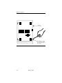
-XPSHU2SWLRQ6HOHFWLRQ &
5HPRYLQJWKH&RYHU &
*URXQG2SWLRQ-XPSHU &
5HSODFLQJWKH&RYHU &
$SSHQGL[')DXOW,VRODWLRQ3URFHGXUH
)DXOW,VRODWLRQ3URFHGXUH '
7HOHSKRQH,QWHUIDFH '
6WDQGDUG3KRQH '
0RGHPDQG7HOHSKRQH/LQH&KHFN '
$SSHQGL[(&RPPDQG,QGH[DQG'HIDXOWV
*HQHUDO (
&DOOHU,'&RPPDQGV(
'LVWLQFWLYH5LQJ&RPPDQGV(
)D[&RPPDQGV(
&ODVV&RPPDQGV9DOLGLQ2QO\)D[0RGH (
6HFXULW\&RPPDQGV(
5HPRWH&RQILJXUDWLRQ&RPPDQGV (
6WDWXV5HJLVWHUV (
9ELV'LDOHU&RPPDQGV(
95HVSRQVH0HVVDJHV(
)DFWRU\2SWLRQ6HWV(
)DFWRU\2SWLRQ6HW(
)DFWRU\2SWLRQ6HW(
)DFWRU\2SWLRQ6HW6\QFKURQRXV'LDOXS$7) (
)DFWRU\2SWLRQ6HW(
9
[[L
7DEOHRI&RQWHQWV
)DFWRU\2SWLRQ6HW$V\QFKURQRXVZLUH/HDVHG/LQH
ZLWK9ELV3URWRFRO$7) (
)DFWRU\2SWLRQ6HW$V\QFKURQRXVZLUH/HDVHG/LQH
ZLWKRXW9ELV3URWRFRO$7) (
)DFWRU\2SWLRQ6HW6\QFKURQRXVZLUH/HDVHG/LQH
1RUPDO2ULJLQDWH$7)(
)DFWRU\2SWLRQ6HW6\QFKURQRXVZLUH/HDVHG/LQH
)RUFHG$QVZHU$7)(
)DFWRU\2SWLRQ6HW6\QFKURQRXV9ELV'LDOHU$7) (
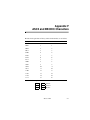
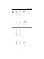
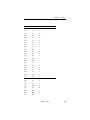
$SSHQGL[)$6&,,DQG(%&',&&KDUDFWHUV
$SSHQGL[*$EEUHYLDWLRQVDQG$FURQ\PV
$SSHQGL[+)ODVK8SJUDGH
:KDW<RX1HHG +
6WHSV)RU'RZQORDGLQJ +
7URXEOHVKRRWLQJ +
6HUYLFHDQG6XSSRUW
,QGH[
[[LL
9
Chapter 1
Introduction
The Modem 3600 provides synchronous, asynchronous, and fax
capabilities for data communications or facsimile links between a local
computer and a remote computer, fax, or data terminal equipment (DTE)
located anywhere a standard or cellular telephone can reach. Data can be
transmitted over standard dial-up lines, private leased telephone lines, or
wireless communication.
The Modem 3600 communicates at standard data rates up to 33,600 bps
with compatible modems connected to similarly equipped computers,
computer services, and data bases. Advanced error control and data
compression ensure data integrity and increase data throughput.
When used with a Class 1 Fax software package, the modem can exchange
fax documents at data rates up to 14,400 bps with any Group 3 fax
machine or PC with a fax modem.
A high-level security feature allows secure operation of the modem, both
locally and remotely.
Shelf-Mount Units
This User’s Guide supports the desktop and shelf-mount versions of the
Modem 3600. Operation and function are generally the same for both, but
when there is a difference, the information primarily supports the desktop
unit. Installation for each version is described in Chapter 2.
Modem 3600
1-1
Introduction
Features
The Modem 3600 is a flexible telecommunications tool that offers the
following standard features.
Data Mode
• Full-duplex operation on two-wire public connections or two-wire
or four-wire private telephone connections with two-wire public
automatic or manual backup
• 300, 1200, 2400, 4800, 7200, 9600, 12000, 14400, 16800, 19200,
21600, 24000, 26400, 28800, 31200, 33600 bps DCE data rates
• Compatible with these standards:
CCITT V.34
CCITT V.33
CCITT V.32 bis
CCITT V.32
CCITT V.29
CCITT V.27
CCITT V.22 bis
CCITT V.22
CCITT V.21
CCITT V.13
Bell 212A
Bell 103
• Compatible with a variety of software packages
• Synchronous operation at all DCE data rates except Bell 103 300
and V.23
• Asynchronous operation at all DTE data rates up to 230.4 kbps
• CCITT V.42 bis and MNP level 5 data compression
• CCITT V.42 and MNP 4 error control protocol
• LCD configuration and status for easy operation
• Front panel lockout
• Autodial and Autoanswer capability
• Autobaud DTE rate and character format selection
• AT command set
• V.25 bis autodialer
• Configuration memory
• Phone number storage
1-2
Modem 3600
Introduction
• Caller ID
• Distinctive ring
• Multiple levels of security with auto callback and password
protection and up to 50 users
• Automatic speed matching to originating modem
• Remote configuration using command mode or LCD
• Built-in standard diagnostics for testing phone line quality and
modems at each end
• Flash upgrades
Fax Mode
•
•
•
•
Fax speeds to 14.4 kbps
HDLC framing to allow T.30 Error Correction Mode
Standard Class 1 interface conforms to EIA-578
Group 3 compatibility: CCITT V.21 Channel 2, V.27 ter, V.29,
V.17
• Autoanswer under software control
• Automatic fax/data detection
Software
Software operates the features of the Modem 3600.
Communications Software
You must have communications software to transfer data. After
installing the modem, consult your communications software user's
manual for information on the software, commands, and features.
Class 1 Fax Communications Software
For sending faxes, a Class 1 fax software package is required.
Internet Browser
To connect to the Internet, Internet browser software is required.
Modem 3600
1-3
Introduction
Description
Functional
The Modem 3600 processes serial asynchronous data from a DTE at all
standard rates from 300 bps to 230.4 kbps*, and serial synchronous data
at rates from 300 to 33.6 kbps. Transmission can be over either dial-up
lines or either two- or four-wire leased lines. The maximum line speed is
33.6 kbps. Built-in test features can determine system performance and
isolate faults in the data link. Operation and configuration are controlled
by the front panel LCD, the AT command set, or the V.25 bis command
set.
*The 230.4 kbps DTE speed is available, but the Modem 3600 will not
autobaud to 230.4 kbps. With the modem set for 115.2 kbps, enter
AT\J2 to enable the speed and enter AT\J3 to disable it.
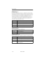
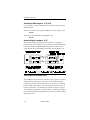
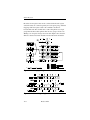
Physical
The Modem 3600 has a 32 character LCD front panel with three
pushbuttons for option selection (Figure 1-1).
Modem 3600
Figure 1-1. Typical Front Panel
1-4
Modem 3600
Introduction
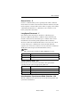
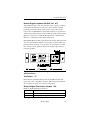
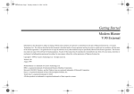
The Modem 3600 rear panel has an EIA-232 DTE connector, an 8-pin
TELSET/LEASED LINE jack, an 8-pin DIAL jack, the power switch,
fuse, and cord (Figure 1-2).
TELSET
LEASED LINE
DIAL
Figure 1-2. Rear Panel (115 Vac Model)
Modem 3600
1-5
Introduction
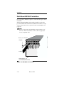
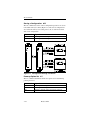
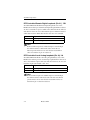
Modem 3600 Card
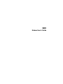
The shelf-mount Modem 3600 unit (Figur e1-3) has edge connectors
that insert into the shelf backplane. The shelf backplane performs the
same functions as the standalone rear panel. Refer to the “Shelf-Mount
MD1000C Installation” on page 10.
Figure 1-3. Card Version of the Modem 3600
1-6
Modem 3600
Chapter 2
Installation
This chapter provides information on mechanical and electrical
installation of the modem.
Mounting Accessories
We have included both self-adhesive feet and an adhesive-backed hook
and loop fastener. The feet are for use when the module will be resting on
a surface; the hook and loop is useful when mounting the modem to a PC
or monitor housing or other flat surface.
To install the feet, peel them from the paper backing and place one foot at
each corner of the bottom of the module. To use the hook and loop
fastener, peel the plastic backing from one side and stick to the bottom of
the module; peel the backing from the remaining piece and press the
module firmly to the mounting surface.Once installed using the hook and
loop fastener, the module may be removed from the mounting surface by
grasping the unit and pulling firmly away from the mounting surface. To
re-mount, align the hook and loop halves and press firmly together.
Modem 3600
2-1
Installation
Electrical Installation
The rear panel (Figure 2-1) includes DTE cable and telephone line
connectors.
TELSET
LEASED LINE
DIAL
Figure 2-1. Rear Panel Connections (115 Vac Model)
AC Power Connection
Power is supplied through a 6-foot line cord with a grounded 3-wire
plug.
DC Power Connection
Caution
To protect the DC-to-DC converter from damage,
ensure the positive and negative leads are properly
connected.
If the modem is equipped for 12-60 VDC power input, connect the
power to the terminal block attached to the modem back panel. A
chassis ground connection is also supplied on the terminal block.
If the modem is equipped for +/- 12/+5 VDC power input, connect the
VDC power to the amp connector. A chassis ground connection is also
supplied on the terminal block.
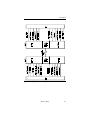
DTE Connection
The DTE connector is a 25-pin D-series type conforming to EIA-232
specifications. You must use a shielded DTE cable to comply with EMC
requirements. Pin signals are shown in Figure 2-2 and are described in
Table 2-1.
2-2
Modem 3600
Installation
Figure 2-2. Digital Interface Signals
Modem 3600
2-3
Installation
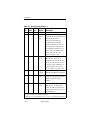
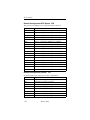
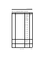
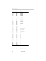
Table 2-1. Pin Signal Description s
Pin
1
EIA- CCITT
232D V.24
Signal
101 Shield
Description
No connection
2
BA
103
Transmitted
Data
Serial digital data (to be
modulated) from a data terminal or
other digital data source:
Synchronous data must be
accompanied by the modem
transmit clock (pin 15) or by an
external data rate clock (pin 24).
Data transitions should occur on
positive-going clock transitions;
asynchronous data does not
require a transmit clock.
3
BB
104
Receive
d Data
Serial digital data output to the
DTE interface: Sync data is
accompanied by an internal data
rate (receive) clock (pin 17) that
has positive-going transitions on
the data transition. Async data
does not require a receive clock.
4
CA
105
Request
to Send
A positive level to the modem
when data transmission is desired
5
CB
106
Clear to
Send
A positive level from the modem
in response to Request to Send and
when the modem is ready to
transmit. *
6
CC
107
Data Set A positive level from the modem
Ready
when power is on and ready to
operate: In dial-up operation, the
modem must be off hook to give a
high DSR signal.*
** Modem options may force these signals on or cause them to be ignored.
*** Refer to Appendix C, Hardware Options.
*† This function can be disabled or its logic sense reversed by hardware straps.
2-4
Modem 3600
Installation
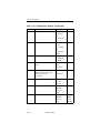
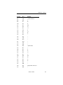
Table 2-1. Pin Signal Descriptions (Continued)
Pin
EIA- CCITT
232D V.24
Signal
Description
7
AB
102
Signal
Ground
Signal or common signal and dc
power ground. **
8
CF
109
Receive A positive level from the modem
d Line
indicating the presence of a
Signal
received signal (carrier detect). *
Detector
9
--
+12
Volts
10
--
-12 Volts -12 voltage reference
11
--
Signal
This circuit indicates probability
Quality of errors in the received data: a
Indicator positive level indicates poor signal
quality while a negative level
indicates good signal quality. †
15
DB
114
Transmit
Clock
(DCE)
A transmit data rate clock output
for use by an external data source:
Positive clock transitions
correspond to data transitions.
17
DD
115
Receive
Clock
A receive data rate clock output
for use by an external data sink:
Positive clock transitions
correspond to data transitions.
18
--
141
Local
Loopback
A positive level causes the modem
to enter the local analog loopback
test mode.*
+12 voltage reference
** Modem options may force these signals on or cause them to be ignored.
*** Refer to Appendix C, Hardware Options.
*† This function can be disabled or its logic sense reversed by hardware straps.
Modem 3600
2-5
Installation
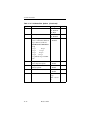
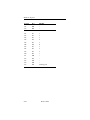
Table 2-1. Pin Signal Descriptions (Continued)
Pin
EIA- CCITT
232D V.24
Signal
Description
20
CD
108.2
Data
Terminal
Ready
This circuit is positive when the
DTE is ready to originate or
answer a call in dial-up operation.
DTR must always be active (high)
in 2-wire private line operation.
Cycling DTR causes retraining.*
21
--
140
Remote
Digital
Loopback
A positive level causes a digital
loopback test mode at the remote
modem.*
22
CE
125
Ring
In direct dial operation this circuit
Indicator is positive in response to an
incoming ring signal.*
23
CH
111
Data
Rate
Select
Supplies a data rate control input
to select primary or fallback data
rate: Negative voltage selects
primary data rate and positive
voltage selects fallback data rate.*
24
DA
113
External
Transmit
Clock
A serial data rate clock input from
the data source. Positive clock
transitions correspond to data
transitions.
25
--
142
Test
Mode
Indicates the modem is in a test
mode.
** Modem options may force these signals on or cause them to be ignored.
*** Refer to Appendix C, Hardware Options.
*† This function can be disabled or its logic sense reversed by hardware straps.
Telephone Line Connection
The modem operates in these line-related modes:
• Dial
• Leased
2-6
Modem 3600
Installation
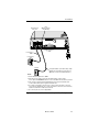
Dial Mode: PSTN Connection (DIAL jack)
The public switched telephone network (PSTN) is a two-wire dial
network. Modems are registered with the Federal Communications
Commission (FCC) for direct connection to the PSTN. The label on the
chassis bottom gives the FCC registration number and other information
required for network operation.
Direct connection to the PSTN is shown in Figure 2-3.
8-pin
Connectors
TELSET
LEASED LINE
DTE Connector
Screws
DIAL
DTE
Cable supplied
with telephone
EIA-232
25-Pin Connector
to DTE
Shielded DTE Cable
RJ11C jack installed
by telephone company
Use 8-pin Modular (at modem end) to 6-pin
Modular (at RJ11 wall jack end) connector.
Notes:
1. The TELSET jack is provided on the back of the modem for use with a
standard rotary or tone dial telephone regardless of the telephone
jack arrangement ordered from the telephone company.
2. This standard rotary or tone dial telephone set can be used for
originating a call or for voice communication. For sites requiring
only auto answer capability, a phone is not needed.
3. For connector pin-outs, refer to Appendix B.
Figure 2-3. Dial-up Connection (115 Vac Model)
Modem 3600
2-7
Installation
Leased Line Connection (TELSET/LEASED LINE Jack)
Private or leased lines use four-wire or two-wire lines. In this mode, the
user configures the unit for four-wire or two-wire operation, depending
on the private line service used.
The telephone company will install the leased line and wall jack at your
site. The line connects to the modem at the 8-position TELSET/
LEASED LINE jack.
Figure 2-4 shows a typical modem hookup for operation over private
leased lines with dial backup.
2-8
Modem 3600
Installation
Dial
(May be used for
Dial Backup)
Telset Leased
Line Jack
TELSET
LEASED LINE
DIAL
DTE
EIA-232
25-Pin Connector
to DTE
Leased Line
Cable
Leased Line
Jack
RJ11C
Use 8-pin Modular (at modem end) to 6-pin
Modular (at RJ11 wall jack end) connector.
(Optional connection for dial backup use.)
Notes:
1. Set the transmit output level to 0dBm.
2. DTR, which is the signal on pin 20 of the DTE interface, must be active
or the option DTE IGNORED must be set for 2-wire OR 4-wire leased line operation.
3. The connection shown includes dial backup. Connect only the leased-line jack
to the modem's Telset jack for regular Leased-line use.
4. For a 2-wire Leased-line connection, Pins 1 and 2 of the Leased-line connection
are used for Tx and Rx data. For a 4-wire Leased-line connection, Pins 1 and 2 are
used for Tx, and Pins 7 and 8 are used for Rx.
5. For connector pin-outs, refer to Appendix B.
Figure 2-4. Leased Line Connection (115 Vac Model)
Modem 3600
2-9
Installation
Shelf-Mount MD1000C Installation
Go to Appendix C, Hardware Options to check the board options before
installation.
Shelf-mount Modem 3600 cards should be installed or replaced by
personnel familiar with shelf-mount installation. The unit has an edge
connector that inserts into a receptacle located on the backplane and
power bus.
Note
Figure 2-5 represents a typical dialup connection using one of
the most common rack shelves. Connect cables as appropriate
for any compatible shelf.
RJ11C, RJ45S or
RJ11C
jack,installed
installed
RJ41S jack
by telephone
company
To DTE
Shelf backplane
(with
MD1000C
installed)
(with RM16M
V.3600
installed)
Figure 2-5. MD1000C Connections
2-10
Modem 3600
Chapter 3
Getting Started
Option Selection
There are six ways to change or select options:
• LCD - Using the front panel LCD and pushbuttons is simple,
straightforward, and requires the least amount of technical
background. Chapter 4 explains LCD operation.
• AT Commands - The AT command set can be used to select modem
options. Chapter 5 describes AT commands.
• Status Registers - A series of special ATS commands allows the
operator to change the decimal or hexadecimal value of a memory
byte to change one or more options in that byte. Chapter 10
describes S-registers.
• Single Bit Status Registers - A second series of special ATS
commands allows the user to change single bits within a byte to
change an option. Chapte r10 also explains single bit control.
• Software Program - A wide variety of software programs is
available, or advanced computer users can write their own software
programs to interact with the modem. This manual does not discuss
software programs.
• V.25 bis Commands - An extended set ofV.25 commands allows
selection of modem options during synchronous operation. Refer to
Chapter 11.
Power-Up
A power-up procedure is not required. Turn on the modem using the ON/
OFF power switch on the rear panel. The modem is factory configured to
operate in most public switched telephone applications. If you have stored
a desired option set it will automatically be restored at power-up.
Modem 3600
3-1
Getting Started
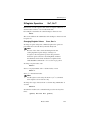
Placing a Call
There are three methods for placing a call:
Dialing with a Standard Telephone
1) Lift the telephone receiver. Wait for the dial tone.
2) Dial the number of the remote site.
3) When the answer back tone is heard, immediately press the
TALK/DATA button and hang up the telephone. The modems go
through a connection sequence and establish a data link. If a data
link is not established, return to Step 1.
4) After the link is established, hang up the telephone.
Autodialing from Front Panel
1) If the number to be dialed has not been stored, advance to Main
Menu #6, CHANGE PHONE NUMBER.
2) Enter the number by using the NO pushbutton to scroll the menu
and YES to select.
3) After the number is entered, press YES to store the number.
4) Advance the LCD to Main Menu #2, DIAL STORED
NUMBER.
5) Select the number to dial and press YES. The number is dialed,
and the modems follow the same process as two telephones.
Autodialing from a Terminal with the AT Commands
To dial a number, for example 555-1212, type AT D 555-1212 and
press Enter, or enter ATDSn where n equals one of the stored telephone
number locations 1-9.
The modem dials the number--either pulse or tone, whichever is
currently in effect--and takes the role of the originate modem.
Refer to the “Dial Commands” section on p age5-13 for additional
dialing commands.
3-2
Modem 3600
Getting Started
Answering a Call
There are three ways to answer a call:
Autoanswering
Normally the modem is configured to autoanswer on the first ring. If a
telephone is plugged into the TELSET/LEASED LINE jack, it will also
ring.
Answering Manually
When detecting a ring, the modem LCD displays ringing status.
Press TALK/DATA to answer the call and place the modem in the data
mode.
Answering from Terminal with AT Command Set
The modem displays the ring response.
To answer a call, type ATA. The modem sends an answer-back tone and
attempts to connect to the remote modem.
Ending a Call
There are two ways to complete a call:
Ending a Call Using the Front Panel
1) Press the TALK/DATA pushbutton. DO YOU WANT TO
DISCONNECT will be displayed.
2) Answer YES.
Ending a Call from a Terminal with the AT Command
Set
1) Enter +++ and the modem will enter command mode.
2) Enter ATH and the modem will terminate the call.
Modem 3600
3-3
Getting Started
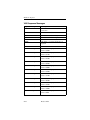
Reasons for Call Termination
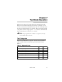
The conditions described in Table 3-1 cause call termination.
Table 3-1. Reasons for Call Terminatio n
Condition
Abort Disconnect
(No answer, busy signal, no modem, etc.)
Description
ATH
Disconnect command.
Loss of Carrier
Disconnect
Select 100 ms to 25.5 sec (S-register 10).
Receive Long Space
Disconnect
Disabled or select 2 sec.
DTR Disconnect
Disabled or select 10 ms to 2.55 sec
(S-register 25).
Default 30 sec; select 1 to 255 sec
(S-register 7).
Loss of Line Current
Cleardown
A disconnect method used inV.32 andV.34
mode.
LCD Display
When TALK/DATA is pressed, the LCD
displays DO YOU WANT TO GO TO
TALK? When YES is pressed modem hangs
up, if no telephone is connected or if the
connected telephone is not off hook. Pressing
NO displays DO YOU WANT TO
DISCONNECT? Press YES to disconnect.
Train Timeout
Modem fails to establish communication
with remote site. Default is 30 seconds
(S-register 7).
Protocol Link
Establishment Failure
Reliable mode only; failure to establish
reliable link.
Inactivity Timeout
Default is 0 or disabled; select for disabled or
1 to 255 minutes (S-register 8).
Protocol Retry Limit
Exceeded
12 retransmissions of the frame.
3-4
Modem 3600
Getting Started
Table 3-1. Reasons for Call Termination (Continued)
Condition
Description
Minimum DCE Speed A connection occurred at a rate less than
minimum.
Security Password
Failure
Maximum password entry attempts
exceeded.
Security Callback
Security callback is enabled and a new
remote connection is established. The modem
disconnects and places a call to the
programmed number.
Signal Quality
Leased line operation with dial backup
enabled; extended loss of carrier or 4
unsuccessful retrains in 3 minutes causes dial
backup.
Test Mode entered
Certain test modes require call termination.
Modem power is
turned off.
Modem 3600
3-5
Chapter 4
Front Panel Operation
The liquid-crystal display (LCD) front panel provides easy real-time
access to modem configuration and status. You can use the LCD at any
time to modify modem options or to get information about modem
operation and status. All of the major modem options can be controlled
through the LCD interface without an external terminal or phone line
connection. Operation of the LCD can be secured using a password
protection feature. A remote modem can even be configured using the
local LCD, through the use of the front panel remote configuration feature.
LED Descriptions
The Modem 3600 LED indicator functions are as follows:
• TR (Terminal Ready). TR lights when the DTE asserts Data
Terminal Ready. This signal is input on pin 20 (CCITT V.24/108.2).
• CS (Clear to Send). CS lights when the modem is ready to send data
to the DTE. This signal is output on pin 5 (CCITT V.24/106).
• RS (Request to Send). RS lights when the DTE is ready to send data
to the modem. This signal is input on pin 4 (CCITT V.24/105).
• CD (Carrier Detect). CD lights when the received audio carrier
signal is detected or, if enabled, when error control protocol
negotiation is complete. This signal is output on pin 8
(CCITT V.24/109).
• RD (Received Data). RD lights for a data space condition at the
receive data output, indicating receive data output activity. This
signal is output on pin 3 (CCITT V.24/104).
• TD (Transmit Data) TD lights for a data space condition at the
transmit data input, indicating transmit data input activity. This
signal is input on pin 2 (CCITTV.24/103).
Modem 3600
4-1
Front Panel Operation
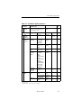
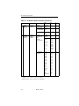
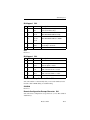
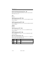
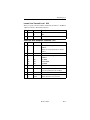
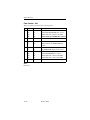
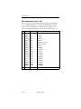
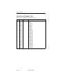
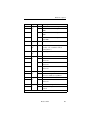
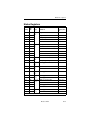
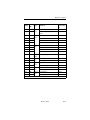
LCD Menus
The Modem 3600 has seven main LCD menus that support modem
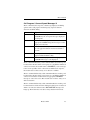
operations. Table 4-1 lists them, in the following sequence:
• MODEM STATUS
• DIAL STORED NUMBER
• DISPLAY STATUS
• SELECT TEST
• MODIFY CONFIGURATION
• CHANGE PHONE NUMBERS
• FRONT PANEL FEATURES
LCD Menu Operation
The LCD menu is shown in Tabl e4-1, as follows:
• The first column lists the seven main menu categories.
• The second column is the submenus, listing functions for each
category in the main menu.
• The third column lists specific items for submenu functions.
• The fourth column lists option choices or status for the specific
items in the third column.
• The fifth and sixth columns in the table show associated AT
commands and S-registers as a cross reference.
Each column item has a corresponding header in the previous column. If
an option setting is selected or if all settings have been scrolled through,
the display returns to the header.
Because of the menu structure and option choices, not all main menus
use all four columns in Tabl e4-1. However, option selection and
sequence are the same.
While operating in the option menu, pressing NO scrolls vertically
down the columns; pressing YES advances horizontally across the
columns. However, responding to the LCD prompt is the best way to
reach an option. If NO is pressed and held, the LCD scrolls through the
menus. Press the TALK/DATA button to return to the previous menu.
4-2
Modem 3600
Front Panel Operation
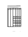
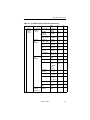
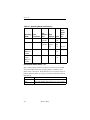
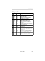
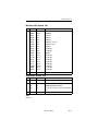
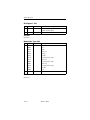
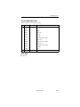
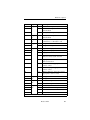
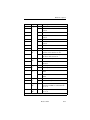
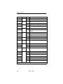
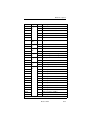
Table 4-1. LCD Menu Option Selectio n
SReg
Main Menu
LCD Messages
1
V.34 33600 IDLE
Shows the current modulation, bit
rate, and modem status.
(Press NO to advance to
MAIN 2)
S91
S67
Submenu
Submenu Item
Item Option
AT Com.
SReg
DIAL #1-9
YES, NO
DSn
(n=1-9)
---
DTE
SIGNALS
QM ON/OFF
DSR ON/OFF
OH ON/OFF
RI ON/OFF
DISPLAY
STATUS
---
---
PROTOCOL*
NONE
MNP 2, 3, 4, 5
LAPM
DISPLAY
STATUS
---
---
COMPRESSOR*
NONE
MNP 5, V.42b
DISPLAY
STATUS
---
---
CARRIER
DESCRIPTIONS*
RECEIVE LEVEL
NEAR END
ECHO
LEVEL
FAR END ECHO
LEVEL
FAR END ECHO
DELAY
FREQUENCY
TRANSLATION
BAUD RATE
RX BIT RATE
TX BIT RATE
DISPLAY
STATUS
---
---
LAST DISCONNECT
REASON
DISPLAY
STATUS
(Offline test
only)
LOCAL ANALOG
LOOP
INITIATE,
EXIT
&T1
S16
LOCAL ANALOG
LOOP WITH TP
INITIATE,
EXIT
&T8
S16
LOCAL DIGITAL
LOOP †
INITIATE,
EXIT
&T3
S16
MODEMSTATUS
Main Menu
2
DIAL
STOREDNUMBER?
3
DISPLAY
STATUS?
(status only)
4
SELECT
TEST?
(Online test)
I5
* When modem is not online, the display flashes and shows the status from the
last connection.
† Modem must be online with protocols disabled.
Modem 3600
4-3
Front Panel Operation
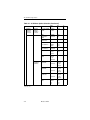
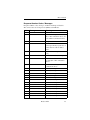
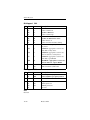
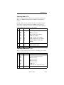
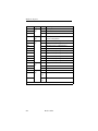
Table 4-1. LCD Menu Option Selection (Continued)
Main Menu
Submenu
Submenu Item
Item
Option
AT
Com.
SReg
4,
(Online test
continued)
REMOTE
DIGITAL LOOP †
INITIATE,
EXIT
&T6
S16
REMOTE DIGI
TAL LOOP WITH
TP †
INITIATE,
EXIT
&T7
S16
TEST PATTERN†
INITIATE,
EXIT
%T
---
CHANGE
LEASED/ DIAL
LINE?
2 WIRE/
4 WIRE
&L1,
&L
S27
AUTOMODE
V.21
BELL 103
B212A
V.22 bis
V.27 ter *
V.29 *
V.33 *
V.32bis
V.34
*MM
*MM1
*MM2
*MM4
*MM5
*MM6
*MM8
*MM10
*MM11
*MM12
S88
33600
31200
28800
26400
24000
21600
19200
16800
600
14400
12000
7200
9600
9600U **
4800
2400
1200
300
DTE SPEED
%B18
%B17
%B16
%B15
%B14
%B13
%B12
%B11
%B10
%B9
%B8
%B7
%B6
%B5
%B4
%B3
%B2
%B1
%B
S69
c
o
n
t.
5
SELECT
TEST?
(continued)
MODIFY
CONFIGURATION?
CHANGE
MODEM
OPTIONS?
CHANGE
MODULATION?
CHANGE MAX
DCE RATE?
*Lease line only.
** 9600U is only valid for V.32 bis modulation.
† Modem must be online with protocols disabled.
4-4
Modem 3600
Front Panel Operation
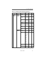
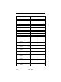
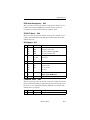
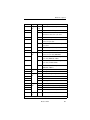
Table 4-1. LCD Menu Option Selection (Continued)
Main Menu
5
c
o
n
t.
MODIFY
CONFIGURATION?
(continued)
Submenu
CHANGE
MODEM
OPTIONS?
(continued)
Submenu
Item
Item
Option
AT
Com.
SReg
CHANGE MIN
DCE RATE?
33600
31200
28800
26400
24000
21600
19200
16800
600
14400
12000
7200
9600
9600U **
4800
2400
1200
300
DTE SPEED
%L18
%L17
%L16
%L15
%L14
%L13
%L12
%L11
%L10
%L9
%L8
%L7
%L6
%L5
%L4
%L3
%L2
%L1
%L
S69
CHANGE V.34
RATE THRESHOLD?
LOW BER
MED BER
HIGH BER
*TH
*TH1
*TH2
---
V.34 ASYM
RATES
ENABLE
DISABLE
*AS1
*AS
S96
NORMAL
ORIGINATE
FORCED
ANSWER*
NORMAL
ORIG.
FORCED
ANS.
*OR
S14
V.22 GUARD
TONE
DISABLE
550 Hz
1800 Hz
&G
&G1
&G2
S23
V.32 FAST TRAIN
ENABLE
DISABLE
*FT1
*FT
S29
AUTO RETRAIN
ENABLE
DISABLE
%E1
%E
S60
SQ AUTO RATE
HIGH BER
MED BER
LOW BER
DISABLED
%R3
%R2
%R1
%R
S53
TRANSMIT
CLOCK
SELECT
INTERNAL
EXTERNAL
RECEIVE
&X
&X1
&X2
S27
*OR1
*Lease line only.
** 9600U is only valid for V.32 bis modulation.
Modem 3600
4-5
Front Panel Operation
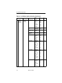
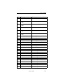
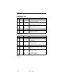
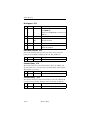
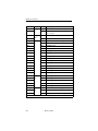
Table 4-1. LCD Menu Option Selection (Continued)
Main Menu
Submenu
Submenu Item
Item
Option
AT
Com.
SReg
5
CHANGE
MODEM
OPTIONS?
(continued)
DIAL TRANSMIT
LEVEL
-9 dBm to
-21 dBm
*TDn
S51
RING
FREQUENCY
LIMIT
ENABLE
*RL1
*RL
--
DISABLE
LEASE TRANSMIT LEVEL*
0 to -21 dBm
*TLn
S52
LINE CURRENT
DISCONNECT†
OFF
SHORT
LONG
*LC,
*LC1,
*LC2
S32
LONG SPACE
DISCONNECT†
ENABLE
DISABLE
Y1
Y
S21
DIAL BACKUP*
MANUAL
AUTOMATIC
*DB
*DB1
S32
LOOKBACK
TIME*
0 DISABLED
to 255
MINUTES
---
S28
LAPM
PROTOCOL
ENABLE
\N4, \N5,
\N6, \N7
\N, \N1,
\N2, \N3
S70
\N2, \N3,
\N6, \N7
\N, \N1,
\N4, \N5
S70
\N3, \N5,
\N6, \N7
\N, \N1,
\N2, \N4
S70
%C
%C1
%C2
%C3
S56
c
o
n
t.
MODIFY
CONFIGURATION?
(continued)
CHANGE
PROTOCOL
OPTIONS?
DISABLE
MNP
PROTOCOL
ENABLE
DISABLE
PROTOCOL
FALLBACK
ENABLE
DISABLE
DATA COMPRESSION
* Lease line only.
† Dial line only.
4-6
Modem 3600
DISABLE
NORM
TX
RX
Front Panel Operation
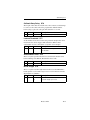
Table 4-1. LCD Menu Option Selection (Continued)
Item
Option
AT
Com.
SReg
DTE SPEED
DTE=DCE
CONSTANT
DTE
\J1
\J
S70
DTE FLOW
CONTROL
DISABLE
XON/XOFF
CTS
RTS/CTS
\Q
\Q1
\Q2
\Q3
S54
DCE FLOW CONTROL
DISABLE
XON/XOFF
CTS
\Q4
\Q5
\Q6, \Q7
S54
XON/XOFF PASS
THROUGH
ENABLE
DISABLE
\X1
\X
S54
INACTIVITY
TIMER
OFF, 15, 30,
45, 60, 75, 90
MIN
\TLn
S58
BREAK
OPTION
0, 1, 2, 3, 4, 5
\K, \K1,
\K2, \K3,
\K4, \K5
S59
V.42 FAST
DETECT
ENABLE
DISABLE
\M1
\M
S70
SYNC
&M1, 2, 3,
4, 5, 6
&M
S27
Main Menu
Submenu
Submenu Item
5
CHANGE
PROTOCOL
OPTIONS?
(continued)
c
o
n
t.
MODIFY
CONFIGURATION?
(continued)
CHANGE DTE DATA
OPTIONS?
OPERATION
ASYNC
S30
DTE RATE
(Async)
300,
600,1200,
2400, 4800,
7200, 9600,
12000,
14400,
16800,
19200,
21600,
24000,
26400,
28800,
31200
33600
38400
57600,
115200
---
S80
CHAR SIZE
(Async)
7 BIT
8 BIT
---
S61
PARITY (Async)
NO, EVEN,
ODD
---
S61
Modem 3600
4-7
Front Panel Operation
Table 4-1. LCD Menu Option Selection (Continued)
Item
Option
AT
Com.
SReg
ASYNC
DTR,
MANUAL,
V.25
BISYNC,
V.25 SDLC
V.25 bis
ASYNC
&M1,
&M2
&M3
&M4
S27
S30
AT COMMAND
SET
ENABLE
DISABLE
*NT1
*NT
S29
CHARACTER
TYPE (V.25 only)
ASCII,
EBCDIC
---
S30
SDLC DATA
FORMAT
NRZ, NRZI
---
S30
DTR STATE
IGNORE
RECALL
CMD
DISCONNECT
RESET
&D
&D1
S21
NORMAL
FORCED
HIGH
OFF 5 SEC
ON
DISCONNECT
FOLLOWS
OH
&S1
&S
NORMAL
FORCED
HIGH
OFF 5 SEC
ON
DISCONNECT
FOLLOWS
REMOTE
RTS
&C1
&C
NORMAL
FORCED
HIGH
CTS
FOLLOWS
DCD
CTS=RTS
&R
&R1
&R2
Main Menu
Submenu
5
CHANGE DTE DIAL METHOD
OPTIONS?
(continued)
c
o
n
t.
MODIFY
CONFIGURATION?
(continued)
Submenu Item
DSR STATE
DCD STATE
CTS STATE
4-8
Modem 3600
&M5
&M6
&D2
&D3
S21
&S2
&S3
S21
&C2
&C3
&R9
S21
S72
Front Panel Operation
Table 4-1. LCD Menu Option Selection (Continued)
Item
Option
AT
Com.
SReg
0 to 150 ms
(10 ms)
---
S26
ENABLE
DISABLE
*FB1
*FB
S53
OPTIONS RES/
RETND AT DISC
RESTORED
RETAINED
*RO1
*RO
S29
BILATERAL
DIGITAL LOOP
ENABLE
DISABLE
*DG1
*DG
S34
DTE LOCAL
TEST
ENABLE
DISABLE
*LA1
*LA
S34
DTE REMOTE
TEST
ENABLE
DISABLE
*RD1,
*RD
S34
REMOTE COMMANDED
ENABLE
DISABLE
&T4
&T5
S23
TEST TIMEOUT
OFF, 60, 120,
180. 240 SEC
---
S18
DIAL TYPE
PULSE,
TONE
P, T
S14
AUTODIAL #
OFF, 1 - 9
*AUn
(n=1-9)
---
DIAL TONE
BLIND
DIAL
WAIT FOR
DIAL
TONE
X, X1, X3
X2, X4
S22
WAIT DELAY
(Blind Dial)
1, 2, 3, 4, 8,
16, 32 SEC
---
S6
PAUSE DELAY
1, 2, 3, 4, 8,
16, 32 SEC
---
S8
CALL TIMEOUT
15, 30, 45,
60, 75, 90,
105, 120 SEC
---
S7
ANSWER RING
#X
1, 2, 4, 8, 16
---
S0
AUTOCALLBACK
ENABLE,
DISABLE
---
S72
VOLUME
CONTROL
LOW
HIGH
L1, L2
L3
S22
Main Menu
Submenu
5
CHANGE DTE RTS/CTS DELAY
OPTIONS?
(continued)
DTE COMMANDED
FALLBACK
c
o
n
t.
MODIFY
CONFIGURATION?
(continued)
CHANGE
TEST
OPTIONS?
CHANGE
DIAL
OPTIONS?
CHANGE
SPEAKER
OPERATION?
Submenu Item
Modem 3600
4-9
Front Panel Operation
Table 4-1. LCD Menu Option Selection (Continued)
Item
Option
AT
Com.
SReg
ON UNTIL
CARR
DETECT
ALWAYS
ON
OFF WHILE
DIALING
ALWAYS
OFF
M1
S22
LOAD
FACTORY
OPTION
NO, 1-9
&Fn
(n=1-9)
---
LOAD USER
OPTION SET
1
2
Z0
Z1
---
STORE PRESENT
OPTIONS
1
2
&W
&W1
---
USER OPTION
AT RESET
1
2
&Y
&Y1
---
Main Menu
Submenu
Submenu Item
5
CHANGE
SPEAKER
OPERATION?
(continued)
SPEAKER
CONTROL
c
o
n
t.
MODIFY
CONFIGURATION?
(continued)
LOAD/STORE
OPTION SET?
M2
M3
M4
6
CHANGE
PHONE
NUMBERS?
PHONE
NUMBER
ENTER
NUMBER
32 digits
&Zx=n
(n=phone #
and modifiers)
*CNx,n
---
7
FRONT
PANEL
FEATURES?
CHANGE RMT
PASSWORD?
ENTER
PASSWORD
%P
---
ENTER REMOTE
CONFIGURATION
ENTER
REM CFG
PASSWORD
%T
---
EXIT REMOTE
CONFIGURATION
EXIT
&T
---
CHANGE FRONT
PANEL PASSWORD
ENTER
PASSWORD
*
---
---
ACTIVATE
SECURITY
---
---
*Password of 0000 disables front panel security.
4-10
Modem 3600
Front Panel Operation
Front Panel Security
The Front Panel Security feature provides password protection for front
panel menu access. The modem is shipped from the factory with this
feature disabled.
The Front Panel Security password is a 4-digit string that can be set to
any combination of digits from “0000” to “9999”. Selecting a password
of “0000” disables Front Panel Security; any other password enables it.
IMPORTANT: Without your password, you cannot access front panel
configuration. Keep your password in a safe place. If you forget your
Front Panel Security password, contact Technical Support. Refer to
“Calling Technical Support” section on page 12-2.
When this feature is enabled, it can be activated in these ways:
• Explicitly, by a front panel screen under Main Menu #7
• By the modem, when no front panel buttons have been pressed for
3 minutes
When Front Panel Security is activated, the front panel menu returns to
Main Menu #1 and the front panel is secured.
In secured state, the Main Menu #1 screen continues to maintain modem
status, but a password must be entered before other front panel screens
may be accessed. Pressing any front panel button causes the modem to
prompt for the front panel password. After the password has been
entered, a message briefly displays the result of the password validation
process and, depending on the result, Front Panel Security either
becomes inactive or returns to its active state.
Modem 3600
4-11
Front Panel Operation
During password entry, the front panel buttons operate as follows:
• Pressing NO makes the character at the cursor change to the next
valid password character.
• Pressing YES while the cursor is on any of the first three
password characters makes the cursor advance to the next
password character. When the cursor is on the last password
character, pressing YES makes the modem accept the displayed
password.
• Pressing TALK/DATA while the cursor is on the first password
character aborts password entry. When the cursor is on any other
character, this button makes the cursor move to the first character.
4-12
Modem 3600
Chapter 5
AT Commands
This chapter describes commands used to select options and operate the
modem. Some options depend on, or are restricted by, the mode of
operation. Appendix E provides a quick reference list.
Command Categories
The modem offers these major categories of command statements:
• Response (page 5-5)
• Dial (page 5-13)
• Answer (page 5-16)
• Terminal Interface (page 5-19)
• General (page 5-22)
• Private Line (page 5-33)
• Configuration (page 5-37)
• Remote Configuration (page 5-41)
Other AT command groups are discussed in these chapters:
• Protocol (Chapter 6)
• Test (Chapter 7)
• Security (Chapter 8)
• Fax (Chapter 9)
• S-registers (Chapter 10)
Operation Modes
In asynchronous operation, the modem functions in one of these modes:
• Offline Command Mode
• Online Command Mode
• Data Mode
Modem 3600
5-1
AT Commands
Offline Command Mode
In offline command mode (generally referred to as command mode), the
modem communicates with the computer or terminal. Commands can
be entered separately or in strings. There is no data communication link
established in this mode.
Online Command Mode
This mode is entered from the data mode after the escape command has
been entered. The escape command is performed by entering the escape
character (+ is the default) three times. The data communication link
remains established but data transmission is suspended. The modem
then accepts commands as it does in offline command mode.
Data Mode
The modem goes to data mode (online) after it acknowledges the proper
signal and successfully connects with a compatible modem. In data
mode, the modem sends and receives data, but does not accept or
execute command instructions.
Example: The modem is in the command state. The D command and
phone number are used to dial a remote modem. The local modem waits
to receive an answer back tone from the remote modem. When the local
modem receives the carrier, it leaves the command state and goes online
in the data mode. At this time, both modems are using the telephone line
and a communication link is established.
Sending Commands to the Modem
When the computer, modem, and monitor are on, an instruction can be
sent to the modem telling it what function or activity to perform. The
instruction, called a command statement, command string, or command,
is typed using the computer/terminal keyboard. The command statement
temporarily resides in a section of memory called the command buffer.
Each command statement is made up of characters, numbers, and
keyboard symbols such as the & and % signs. Commands must be
written in a specific form so the modem recognizes and follows the
instruction.
5-2
Modem 3600
AT Commands
Creating a Command Statement
AT
To create a command statement use the following steps:
1) Type AT. This is the Attention Code telling the unit a command
statement follows.
2) Type the command.
3) Press the Enter key to send the command statement to the
modem.
An example of a command statement using the dial command (D)
follows.
ATD554-1212
This statement can be read as “Attention: Dial 554-1212.”
Another AT command statement example is:
ATZ
This statement can be read as “Attention: execute the Z command.”
After entering a command line the modem returns a response message
indicating whether or not the command was accepted or giving the data
requested by the command line.
To clear command statements from the buffer you can:
• Turn the modem off,
• Enter AT, or
• Use the DTR reset feature (“Data Terminal Ready &D” section on
page 5-20).
Autobaud
The attention code (AT) is analyzed by the modem to determine the
transmission speed, parity, and bits per character used by the DTE. This
autobaud process is repeated each time the AT command prefix is sent.
Guidelines for Creating Command Statements
The attention code (AT) may be upper or lower case but not a
combination like aT.
• Press the Enter key to execute a command.
• The command buffer can hold 80 characters.
• Use the backspace or delete key to erase the last character.
Even though the initial AT code must be all upper or lower case,
characters that follow can be any mix of upper and lower case.
Modem 3600
5-3
AT Commands
Monitor Display
As commands are typed they appear on the monitor so the operator can
verify the input. This is called local character echo. The echo may be
turned on or off using AT commands. Refer to the “Local Character
Echo E” section on page 5-22 for details.
Command Statement Buffer
The modem temporarily stores up to 80 characters in the command
buffer. If this limit is exceeded, the modem does not accept the
command and sends an ERROR message. To correct this condition,
retype the command using 80 characters or less.
The AT characters and punctuation used in telephone numbers do not
take up space in the buffer. Blank characters used as spaces to help
increase readability are not counted. For example, the modem reads the
commands:
ATD (212) 554-1212
ATD2125551212
ATD 212 555 1212
as having 11 characters each. Commands can be typed in any of these
forms.
Backspace Key
Use the backspace key to change the command statement or correct
errors. The backspace key allows the cursor to be moved back to the
character(s) in error. The command can then be retyped from that point.
Example: ATD5551211 has been typed. To change the last 1 to 2,
press the backspace key once, type 2, and press Enter to execute the
command.
Repeating a Command
A/
This command tells the computer to repeat the last command stored in
its buffer. It automatically reexecutes the command without retyping.
The return key does not need to be pressed.
Example: The ATD5551212 command has been executed, and the
phone is busy. To repeat the instruction type A/. Do not use AT before
this command: AT empties the buffer.
5-4
Modem 3600
AT Commands
Numbered Commands
Commands that start with the same letter are distinguished by a number
following the letter.
For example, the M0 command selects speaker always off, M1 speaker
on until carrier detected, and M2 selects speaker always on.
Note
The zero (0) may be omitted; the commands M and M0 are
identical. This manual uses the nonzero form. The modem
treats both the same, but zeros count against the buffer total.
Group Commands
A group of commands can be typed in a single command statement.
Pressing the Enter key sends the entire command string to the modem,
which executes each command individually in the order it appears in the
command statement reading from left to right.
For example, the command statement ATQ0V0L3DT5551212 means
• AT Attention.
• Q Allow response messages to be sent.
• V Select digit code responses.
• L3 Select high volume.
• DT Tone dial 555-1212.
The modem executes the AT command followed by the Q, V, L, D, and T
commands. ATQ0V0L3DT5551212 can be read as
ATQVL3DT5551212. Eliminating zeros reduces the number of
characters, allowing more room in the buffer.
The dial D command initiates the dial process so no other commands,
only dial modifiers, can follow it.
Note
Bold text indicates command parameter defaults.
Response Commands
The modem communicates with the operator through response
messages. These appear on the monitor or a computer printout to show
the result of the command or action executed. Response messages can
appear as words or numbers.
Modem 3600
5-5
AT Commands
Digit / Word Selection V
The V command tells the modem which type of response message to
show on the monitor. Some software requires digit response messages
but words are easier to remember.
Command
Operation
V
Enables digit response messages
V1
Enables word response messages
Response Displays Q
The Q command enables or disables response messages. The modem
still responds to commands when the response display is inhibited.
Command
Operation
Q
Response display on
Q1
Response display off
Q2
Response display on in originate mode only
Negotiation Displays W
The W command enables or disables negotiation response messages.
These messages are verbose negotiation status displays to alert the user
to the link rate, protocol, and DTE rate.
Command
Operation
W
Disables negotiation displays
W1
Enables negotiation displays
W2
Displays DCE link rate only
Protocol Result Codes \V
Enable or disable protocol result codes. Table 5-1 lists these codes.
Command
\V
Disable protocol result codes
\V1
Enable protocol result codes
5-6
Operation
Modem 3600
AT Commands
Call Progress / Connect Speed Messages X
The X command selects response code/message displays and dialing
options such as call progress monitoring, busy signal or dial tone
detection and blind dialing.
Command
Operation
X
Dial tone and busy signal detection not selected;
CONNECT (code 1) response messages displayed
for all speeds
X1
Dial tone and busy signal detection not selected;
appropriate CONNECT response messages or codes
displayed for data rate
X2
Dial tone detection only; NO DIAL TONE message
or code appears if dial tone not detected within 5
seconds
X3
Busy signal detection only; BUSY message or code
appears if dialed number is busy
X4
Dial tone and busy signal detection; appropriate
CONNECT message or code displayed
The X command followed by a dial command makes the modem go off
hook, wait the amount of time set in register S6, and dial the number. If
connection is made, the modem returns a CONNECT (code 1) message
to the screen regardless of the connection rate. With a basic response,
the modem does not detect a busy or no dial tone condition.
The X1 command followed by a dial command makes the modem go off
hook, wait the amount of time set in register S6, and dial the number. If
connection is made the modem returns an appropriate CONNECT
message or code to the screen. The modem does not detect a busy or no
dial tone situation.
The X2 command followed by a dial command makes the modem go off
hook and wait for a dial tone before dialing. If a dial tone is not detected
within 5 seconds, the modem sends a NO DIALTONE message and
hangs up. The modem does not detect a busy situation in this mode.
Modem 3600
5-7
AT Commands
The X3 command followed by a dial command makes the modem go off
hook, wait the amount of time set in register S6 and dial the number. If
a busy signal is detected, the modem sends a BUSY message and hangs
up. If the call is completed, the appropriate CONNECT message similar
to X1 is displayed. The modem does not detect a no dial tone situation.
The X4 command followed by a dial command makes the modem go off
hook and wait for a dial tone before dialing. If a dial tone is not detected
within 5 seconds, the modem returns a NO DIALTONE message and
hangs up. If a busy signal is detected, the modem returns a BUSY
message and hangs up. If the call is completed, the appropriate
CONNECT message similar to X1 is displayed.
The X4 command combines the features of X1, X2, and X3. The factory
setting is X4.
Note
When an X2, X3, or X4 command is in effect, an appropriate
CONNECT data rate message or code is displayed as for X1.
When a blind dial command (X, X1, X3) is in effect, the
modem waits 2 seconds or the time set in S6 and then dials.
Number Code Application *RC
Some communications software packages use different number codes to
indicate the data rate of the serial port. This option selects either of two
commonly used number code sets.
Command
*RC
Code Set
Standard
Number
15
18
Operation
4800 bps
9600 bps
*RC1
Alternate
11
12
4800 b p s
9600 bps
Note
Asterisks in AT commands are part of the command and do
not indicate footnotes.
5-8
Modem 3600
AT Commands
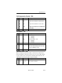
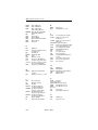
Response Number Codes / Messages
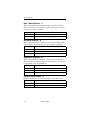
Response number codes, messages, and their meanings are listed in .
The connect rates are serial port rates (DTE), not DCE rates.
Code
Message
Meaning
0
OK
Command received
1
CONNECT
Connect at 300 bps while X1, X2,
X3, or X4 command in effect; all
rates while X command in effect
2
RING
Ring detected
3
NO CARRIER
Valid carrier not detected within
period specified by register S7, or
carrier lost for value of S10 or
more
4
ERROR
Command not recognized or too
long
5
CONNECT 1200
Connection made at 1200 bps
6
NO DIAL TONE
No dial tone detected for 5
seconds (X2 or X4 command in
effect)
7
BUSY
Dialed number busy (X3 or X4
command in effect)
10
CONNECT 2400
DTE rate 2400 bps
11, 15
CONNECT 4800
DTE rate 4800 bps
12, 18
CONNECT 9600
DTE rate 9600 bps
20
CONNECT 300
DTE rate 300 bps
22
CONNECT 7200
DTE rate 7200 bps
23
CONNECT 12000
DTE rate 12000 bps
24
CONNECT 14400
DTE rate 14400 bps
25
CONNECT 16800
DTE rate 16800 bps
26
CONNECT 19200
DTE rate 19200 bps
27
CONNECT 21600
DTE rate 21600 bps
28
CONNECT 24000
DTE rate 24000 bps
29
CONNECT 26400
DTE rate 26400 bps
30
CONNECT 28800
DTE rate 28800 bps
Modem 3600
5-9
AT Commands
Code
Message
Meaning
31
CONNECT 31200
DTE rate 31200 bps
32
CONNECT 32000
DTE rate 32000 bps
33
CONNECT 33600
DTE rate 33600 bps
34
CONNECT 38400
DTE rate 38400 bps
35
CONNECT 57600
DTE rate 57600 bps
36
CONNECT 115200
DTE rate 115200 bps
37
CONNECT 230400
DTE rate 230400 bps
38
CONNECT 300/V42bis
V.42 bis 300 bps connection
39
CONNECT 600/V42bis
V.42 bis 600 bps connection
40
CONNECT 1200/V42bis
V.42 bis 1200 bps connection
41
CONNECT 2400/V42bis
V.42 bis 2400 bps connection
42
CONNECT 4800/V42bis
V.42 bis 4800 bps connection
43
CONNECT 7200/V42bis
V.42 bis 7200 bps connection
44
CONNECT 9600/V42bis
V.42 bis 9600 bps connection
45
CONNECT 12000/
V42bis
V.42 bis 12000 bps connection
46
CONNECT 14400/
V42bis
V.42 bis 14400 bps connection
47
CONNECT 16800/
V42bis
V.42 bis 16800 bps connection
48
CONNECT 19200/
V42bis
V.42 bis 19200 bps connection
49
CONNECT 21600/
V42bis
V.42 bis 21600 bps connection
50
CONNECT 24000/
V42bis
V.42 bis 24000 bps connection
51
CONNECT 26400/
V42bis
V.42 bis 26400 bps connection
52
CONNECT 28800/
V42bis
V.42 bis 28800 bps connection
53
CONNECT 31200/
V42bis
V.42 bis 31200 bps connection
5-10
Modem 3600
AT Commands
Code
Message
Meaning
54
CONNECT 32000/
V42bis
V.42 bis 32000 bps connection
55
CONNECT 33600/
V42bis
V.42 bis 33600 bps connection
56
CONNECT 38400/
V42bis
V.42 bis 38400 bps connection
57
CONNECT 57600/
V42bis
V.42 bis 57600 bps connection
58
CONNECT 115200/
V42bis
V.42 bis 115200 bps connection
59
CONNECT 230400/
V42bis
V.42 bis 230400 bps connection
60
CONNECT 300/V42
V.42 300 bps connection
61
CONNECT 600/V42
V.42 600 bps connection
62
CONNECT 1200/V42
V.42 1200 bps connection
63
CONNECT 2400/V42
V.42 2400 bps connection
64
CONNECT 4800/V42
V.42 4800 bps connection
65
CONNECT 7200/V42
V.42 7200 bps connection
66
CONNECT 9600/V42
V.42 9600 bps connection
67
CONNECT 12000/V42
V.42 12000 bps connection
68
CONNECT 14400/V42
V.42 14400 bps connection
69
CONNECT 16800/V42
V.42 16800 bps connection
70
CONNECT 19200/V42
V.42 19200 bps connection
71
CONNECT 21600/V42
V.42 21600 bps connection
72
CONNECT 24000/V42
V.42 24000 bps connection
73
CONNECT 26400/V42
V.42 26400 bps connection
74
CONNECT 28800/V42
V.42 28800 bps connection
75
CONNECT 31200/V42
V.42 31200 bps connection
76
CONNECT 32000/V42
V.42 32000 bps connection
77
CONNECT 33600/V42
V.42 33600 bps connection
78
CONNECT 38400/V42
V.42 38400 bps connection
79
CONNECT 57600/V42
V.42 57600 bps connection
Modem 3600
5-11
AT Commands
Code
Message
Meaning
80
CONNECT 115200/V42
V.42 115200 bps connection
81
CONNECT 230400/V42
V.42 230400 bps connection
82
CONNECT 300/MNP5
MNP5 300 bps connection
83
CONNECT 600/MNP5
MNP5 600 bps connection
84
CONNECT 1200/MNP5
MNP5 1200 bps connection
85
CONNECT 2400/MNP5
MNP5 2400 bps connection
86
CONNECT 4800/MNP5
MNP5 4800 bps connection
87
CONNECT 7200/MNP5
MNP5 7200 bps connection
88
CONNECT 9600/MNP5
MNP5 9600 bps connection
89
CONNECT 12000/MNP5 MNP5 12000 bps connection
90
CONNECT 14400/MNP5 MNP5 14400 bps connection
91
CONNECT 16800/MNP5 MNP5 16800 bps connection
92
CONNECT 19200/MNP5 MNP5 19200 bps connection
93
CONNECT 21600/MNP5 MNP5 21600 bps connection
94
CONNECT 24000/MNP5 MNP5 24000 bps connection
95
CONNECT 26400/MNP5 MNP5 26400 bps connection
96
CONNECT 28800/MNP5 MNP5 28800 bps connection
97
CONNECT 31200/MNP5 MNP5 31200 bps connection
98
CONNECT 32000/MNP5 MNP5 32000 bps connection
99
CONNECT 33600/MNP5 MNP5 33600 bps connection
100
CONNECT 38400/MNP5 MNP5 38400 bps connection
101
CONNECT 57600/MNP5 MNP5 57600 bps connection
102
CONNECT 115200/
MNP5
MNP5 115200 bps connection
103
CONNECT 230400/
MNP5
MNP5 230400 bps connection
104
CONNECT 300/MNP
MNP 300 bps connection
105
CONNECT 600/MNP
MNP 600 bps connection
106
CONNECT 1200/MNP
MNP 12000 bps connection
107
CONNECT 2400/MNP
MNP 24000 bps connection
108
CONNECT 4800/MNP
MNP 4800 bps connection
109
CONNECT 7200/MNP
MNP 7200 bps connection
5-12
Modem 3600
AT Commands
Code
Message
Meaning
110
CONNECT 9600/MNP
MNP 9600 bps connection
111
CONNECT 12000/MNP
MNP 12000 bps connection
112
CONNECT 14400/MNP
MNP 14400 bps connection
113
CONNECT 16800/MNP
MNP 16800 bps connection
114
CONNECT 19200/MNP
MNP 19200 bps connection
115
CONNECT 21600/MNP
MNP 21600 bps connection
116
CONNECT 24000/MNP
MNP 24000 bps connection
117
CONNECT 26400/MNP
MNP 26400 bps connection
118
CONNECT 28800/MNP
MNP 28800 bps connection
119
CONNECT 31200/MNP
MNP 31200 bps connection
120
CONNECT 32000/MNP
MNP 32000 bps connection
121
CONNECT 33600/MNP
MNP 33600 bps connection
122
CONNECT 38400/MNP
MNP 38400 bps connection
123
CONNECT 57600/MNP
MNP 57600 bps connection
124
CONNECT 115200/MNP MNP 115200 bps connection
125
CONNECT 230400/MNP MNP 230400 bps connection
Dial Commands
Dial commands let the modem originate a call to another modem. These
commands can be used with either tone or pulse dial telephone systems.
Dialing D
To dial a number, for example 555-1212, insert the D command in
the dialing sequence.
AT D 555-1212
The modem dials the number, either pulse or tone, whichever is in
effect, and takes the role of the originate modem.
Use spaces, hyphens, parentheses, or other punctuation, except dial
modifiers, to make the command line easier to read and enter. For
example, these are all treated the same:
AT D 1-800-555-1212
AT D 1 (800) 555-1212
ATD18005551212
Modem 3600
5-13
AT Commands
Dial modifiers are as follows.
Command
Operation
T
Tone dialing
P
Pulse dialing
,
Insert a long pause (2 sec or value in S8)
W
Wait for 2nd dial tone
!
Flash (1/2 sec)
R
Switch to answer mode after dialing
;
Return to command mode after dialing
@
Wait for silence
S
Dial stored command line or number
Tone Dialing T
To tone dial a number sequence, insert a T in the dial sequence.
AT D T 323-1111
In this example, the modem tone dials the telephone number. The
dialing method selected remains in effect until changed.
Pulse Dialing P
To pulse dial a number sequence, insert a P in the dial sequence.
AT D P 554-9902
Insert Long Pause ,
To insert a long pause in the dialing sequence, use a comma. This inserts
a 2 second delay (or the value in register S8).
AT D P 9, 1-800-554-1000
Here the modem pulse dials a 9, pauses for the telephone system to
switch to an outside line, then dials the phone number. Comma pauses
may be inserted consecutively if desired.
Wait for Second Dial Tone
W
To wait for second dial tone insert a W in the dialing sequence.
AT D 9 W 323-8000
Instead of using a comma pause for an outside line, wait up to 30
seconds (time specified by S7) for a second dial tone.
5-14
Modem 3600
AT Commands
Hook Flash !
To flash the switchboard, insert an exclamation mark in the dialing
sequence.
AT D T 9W 323-8000 ,!, #7 377
This inserts a 0.5 second on hook condition, usually for transferring a
call or similar use.
In this example, the modem tone dials a 9, waits for the second dial
tone, dials the phone number, pauses, flashes to start the transfer, pauses
a second time, then uses #7 to transfer the call to extension 377.
Switching to Answer Mode after Dialing R
To switch to answer mode after dialing, use an R at the end of the dial
sequence.
AT D 554-2345 R
Use this command suffix to call an originate-only modem.
Remaining in Command Mode ;
To remain in command mode after dialing, place a semicolon at the end
of the dial sequence.
AT D 234-5678;
The modem will dial the telephone number entered but will not attempt
to train when the remote service answers the call.
This is used to retain control so that further dialing tones may be entered
with the following:
AT DTn;
where n= additional tones to be sent.
Wait for 5 Seconds of Silence
@
To wait for 5 seconds of silence (no answer back tone) after accessing
an electronic service, use the @ command in the dialing sequence.
AT D 399-4700 @ 2251 ;
In this example the modem dials the number and, after the connection,
waits for 5 consecutive seconds of silence. The modem then sends
service code 2251 and returns to command mode for further input.
Modem 3600
5-15
AT Commands
For example, you might enter a dollar amount for a banking transaction
by entering
AT D 1400 ;
This sends the sequence 1400 and then returns to the command mode
for further entries, according to the requirements of the banking service.
Dialing a Stored Telephone Number
Sn
To dial one of the previously stored numbers, enter Sn where n
represents a stored telephone number location between 1 and 9.
AT D S9
In this example, the number stored in location 9 is dialed.
Note
DS and DS1 are the same location.
Autodial Number Location
*AUn
The *AUn command selects stored number n (n=1 to 9) to be
autodialed. This is the autodial number, which is used for any autodial
application.
Voice Calls
To make a voice call, dial the number with the telephone. To use the dial
command for the call, enter the following dialing sequence:
AT D (number);
The ; modifier recalls the command mode and prevents the modem from
training. The remote site must be answered by the telephone for the
voice call to be successful.
Switching from Voice to Data
After dialing, place the modems at both ends in data mode by pressing
the TALK/DATA button. The *DA1 command can also be used to
change from talk mode to data mode.
Answering A Call
There are three ways to answer a call for a data connection:
• Manually
• AT Command
• Autoanswer
5-16
Modem 3600
AT Commands
Manual Answer
When the phone rings, answer by pressing the TALK/DATA button.
AT Command Answer A
The modem can be made to answer a call by entering ATA when the
phone rings.
Autoanswer S0
Autoanswer is controlled by register S0. S0 determines which ring the
modem answers on. S0 can be loaded with a value between 1 and 255
for autoanswer. Entering ATS0=0 disables autoanswer. Decide which
ring the modem is to answer on and set S0 to that decimal value.When
S0 is one or greater, the modem automatically answers on the selected
ring and connects with the calling modem.
Note
If the modem is set to respond to DTR the DTR signal must
be on for autoanswer to work.
Caller ID
*ID
If the telephone company is providing Caller ID services to the local
phone line, the Modem 3600 can report Caller ID to the DTE. *
Note
The communications software package may need
reconfiguring to look for the “Caller Number:” message
prefix so that it knows when to look for a phone number.
Command
Operation
*ID
Disable Caller ID
*ID1
Enable Caller ID
Modem 3600
5-17
AT Commands
When Caller ID is enabled, one of the messages in Table 5-2 appears on
the computer screen after the first RING message:
Table 5-2. Caller ID Message s
The modem sends this message... If:
CALLER<sp>NUMBER:
(505)555-1313
The number was delivered
by the phone company
CALLER<sp>NUMBER:OUT<sp> OF
<sp>AREA
The number was not
available from the phone
company
CALLER<sp>NUMBER:PRIVATE
Delivery was blocked by
the caller
CALL FAILURE<sp>NUMBER:
ERROR
The number was received
in error
If the telephone company provides Enhanced Caller ID, the caller's
name appears after the caller phone number.
Distinctive Ring
*DR
If the telephone company is providing distinctive ring service to the
local phone line, the Modem 3600 can report the type of ring to the
DTE.* The data communications software package must allow
distinctive ring.
*Caller ID and Distinctive Ring are compatible only with USA
standards.
Command
Operation
*DR=0
Disable Distinctive Ring
*DR=1
Enable Distinctive Ring
5-18
Modem 3600
AT Commands
When distinctive ring is enabled, one of the messages in Table 5-3
appears on the DTE instead of the regular RING message:
Table 5-3. Distinctive Ring Message s
The modem sends this
message...
If the Ring Was a:
RING A
Single ring (1 ring burst)
RING B
Double ring (2 ring bursts)
RING C
Triple ring (3 ring bursts)
Terminal Interface Commands
The EIA-232 interface connects the modem and DTE. Terminal
interface commands control the action of the modem and the terminal in
response to the signals being exchanged on the interface pins. Refer to
Table 2-1.
Data Carrier Detect &C
When using DCD to indicate a valid carrier, use the &C1 command.
Some terminals and other devices require DCD on in order to
communicate with the modem; if so, use the &C command.
Command
&C
Operation
DCD always on
&C1
DCD on when modem recognizes remote modem
carrier or, if enabled, when protocol negotiation is
complete.
&C2
DCD on except for 5 seconds after disconnect
&C3
DCD follows RTS on remote modem (simulated
switched carrier V.13).
Note
AT&C3 is used to simulate switched carrier operation.
Note
For simulated switched carrier operation &C3 must be
selected on both modems. Not available in the B103 and V.21
modulation modes.
Modem 3600
5-19
AT Commands
Data Set Ready &S
These commands control the DSR signal generated by the modem to
indicate that the modem is ready for operation. DSR must be on for
some terminals and devices to communicate with the modem.
Command
Operation
&S
DSR always on
&S1
DSR on when off hook in data mode
&S2
DSR off for 5 seconds after disconnect then returns
to on
&S3
DSR follows off hook (OH) signal
Data Terminal Ready &D
In data mode DTR may be used for modem control.
Command
Operation
&D
The modem ignores DTR.
&D1
The modem goes to command mode from data
mode when DTR goes from on to off.
&D2
Disconnects when DTR goes from on to off;
disables autoanswer while DTR is off.
&D3
Disconnects, recalls command mode, and resets the
modem to a stored configuration when DTR goes
from on to off.
In dial line mode the modem disconnects; in leased
line, the modem retrains.
Note
If DTR controls dialer is selected, selecting DTR active will
cause an autodial after an off-to-on transition of DTR.
5-20
Modem 3600
AT Commands
Serial Port Ring Indicator (Pin 22) \R
The \R commands determine how the ring indicate signal operates on
pin 22 of the EIA-232 DTE connector.
Command
Operation
\R
Causes ring indicate signal on pin 22 to turn on
(high) during each ring and remain on during the
call
\R1
Causes ring indicate signal on pin 22 to turn on
(high) during each ring and turn off (low) when the
call is answered
Request to Send / Clear to Send &R
When the modem is operating in nonbuffered mode (direct mode) or in
synchronous mode, &R enables the RTS-to-CTS delay determined by
the value in S26. &R1 forces CTS high and the modem ignores RTS
(default). With &R2 selected, CTS goes high when carrier is detected.
&R9 forces CTS to follow the state of RTS without delay.
Command
Operation
&R
Enables RTS-to-CTS delay
&R1
CTS forced on
&R2
CTS follows DCD
&R9
CTS equals RTS
Note
RTS/CTS delay is not valid in buffered mode or with error
control enabled.
Note
With &R2 selected, XON/XOFF is the only valid method of
flow control and &C and &C1 are the only valid carrier detect
options.
Modem 3600
5-21
AT Commands
DTE Controlled Fallback Rate (Pin 23) *FB
Pin 23 of the EIA-232 DTE connector provides signal input to the
modem for DTE fallback. If the modem is not using DTE fallback, set
this option to ignore pin 23. To cause the modem to act on high/low
levels of pin 23, enable this option. Negative level forces a higher rate
for primary data rate; positive forces a lower rate providing a fallback
rate.
Command
*FB
Operation
Ignore pin 23
*FB1
Transition on pin 23 changes speed
General Commands
This series of commands controls various standard options that in most
cases apply to any mode of operation.
Changing from Data Mode to Command Mode +++
To exit data mode and go to online command mode, press the escape
character three times (+ is the default). Pause for the length of time set
by register S12 (1 second is the default) before and after the +++ to
ensure the modem recognizes the escape command.
This sequence temporarily suspends data mode transmissions and
allows command mode operations without breaking or otherwise
disturbing the telephone line connection. The modem responds with OK
when it detects the escape code. Return to data mode by entering the O
command.
Note
The AT command set must be enabled.
Local Character Echo E
Type AT without a carriage return. If the screen shows AT character,
echo is correct. Proceed with other commands as desired.
If the screen shows AATT, enter the E command to correct the double
characters or disable character echo by the modem.
5-22
Modem 3600
AT Commands
If the screen shows no characters, enter the E1 command to turn modem
echo on or enable local echo on the terminal.
Command
E
Operation
Echo off
E1
Echo on
Online Character Echo F
In some lower speed modems the F command determines if characters
are echoed to the DTE from the modem when online. This function is
generally controlled by the communications software. The modem does
not support online character echo.
Hanging Up H, H1
To end a call, enter the H command. This tells the modem to disconnect
and go on hook. The modem must be in command mode to use this
command.
Enter the H1 command to take the modem off hook. The modem
automatically goes off hook when a dial command is keyed in.
Fast Disconnect H2, H3
The results of the H command can be modified by the H2 and H3
commands. H2 or H3 will not cause a hang up but will affect the method
of hanging up the next time the H command is issued. If H2 is entered,
the H command will hang up according to CCITTV.32 standards. If
operating in V.32 bis mode the H2 command could take several seconds.
If H3 (the fast command) is entered, the H command will hang up much
more rapidly at those speeds.
Command
Operation
H
The modem hangs up.
H1
Forces modem off hook
H2
Sets H command to normal hangup procedure (long
space, cleardown, protocol)
H3
Sets H command to fast hang up
Modem 3600
5-23
AT Commands
EPROM Check I
PC software packages may issue the I command to verify the modem
will support all commands needed by the software package. The modem
returns ASCII characters representing the model and revision level. To
request the checksum to be calculated on the EPROM, enter the I1
command. The modem returns four ASCII characters representing the
cyclic redundancy check (CRC) in hexadecimal form. Enter the I3
command to request the product version.
Command
I
Operation
Request product code
I1
Request EPROM checksum value
I3
Request product version
I4
Returns Motorola V.3600
I5
Last disconnect reason
Speaker Volume L
The L commands offer three volume levels.
Command
Operation
L, L1, L2
Speaker volume low
L3
Speaker volume high
Speaker Control M
The M commands enable or disable the speaker for monitoring purposes.
Command
Operation
M
Disables the speaker
M1
Disables the speaker while receiving a carrier signal
M2
Speaker always on
M3
Disables the speaker while dialing and after a
carrier is detected
5-24
Modem 3600
AT Commands
Return Online O
Use the O command when you are operating in the online command
mode and need to return to data mode. It returns the modem to the same
mode (originate or answer) that it was in before escaping to the (online)
command mode. Enter the O1 command to cause a retrain to occur
before going back to data mode.
Long Space Disconnect Y
One method of disconnecting two modems is called long space
disconnect. When any disconnect condition is detected by the local
modem, it will send 4 seconds of data space condition to the remote
modem before disconnecting. This signals the remote modem to
disconnect. The local modem will disconnect if it receives 1.6 or more
seconds of data space condition from a remote modem. If break
sequences of 1.6 or more seconds are to be sent, enter the Y command to
disable this feature and prevent unintentional disconnects.
Note
This option must be disabled if SDLC NRZI data is used.
Command
Operation
Y
Long space disconnect off
Y1
Long space disconnect on
V.22 bis Guard Tones &G
Guard tones are not used in the United States. If required where
operating the unit, select the appropriate guard tone.
Command
&G
No guard tone
Operation
&G1
550 Hz guard tone
&G2
1800 Hz guard tone
Asynchronous / Synchronous Mode Selection &M
The &M commands select synchronous or asynchronous operation and
synchronous dial method.
Modem 3600
5-25
AT Commands
Use register S30 to select NRZ/NRZI for data format if using SDLC.
Command Operation
&M
Async data/dialer mode (V.25 bis disabled)
&M1
Sync data mode / async dialer
&M2
Sync data mode / DTR dials if active
&M3
Sync data mode / manual dial
&M4
Sync data mode (ASCII) with V.25 bis BISYNC dialer
&M5
Sync data mode (NRZ) with V.25 bis SDLC dialer
&M6
Sync data mode with V.25 bis async dialer
&M7
Async data mode with V.25 bis async dialer
&M8
Sync data mode (EBCDIC) with V.25 bis BISYNC dialer
&M9
Sync data mode (EBCDIC, NRZ) with V.25 bis async
dialer
&M10
Sync data mode (ASCII, NRZI) with V.25 bis SDLC
dialer
&M11
Sync data mode (EBCDIC, NRZI) with V.25 bis SDLC
dialer
IMPORTANT: Synchronous DTE must be available to communicate
with the modem if the V.25 bis dialer is enabled.
Make / Break Dial Pulse Ratio &P
Use the &P command for the dial pulse to be on for 39% and off for
61% of one cycle. Use the &P1 command for the dial pulse to be on for
33% and off for 67% of one cycle.
Command
&P
Operation
39% : 61% US and Canada
&P1
33% : 67%
5-26
Modem 3600
AT Commands
Synchronous Transmit Clock Source &X
The &X commands select internal, external, or receive clock as the
transmit clock source.
Command
Operation
&X
Internal clock
&X1
External clock
&X2
Receive clock
V.34 Rate Selection Thresholds *TH
The *TH commands sets theV.34 rate selection thresholds. TheV.34
modulation dynamically selects the optimum bit rate to run, based on
line quality.
Command
*TH
Operation
Low V.34 threshold (10 - 6 BER)
*TH1
Medium V.34 threshold (10- 4 BER)
*TH2
High V.34 threshold (10- 2 BER)
V.34 Asymmetric Bit Rates *AS
The *AS command enables or disables the V.34 asymmetric bit rate
capability. This feature allows the modem to run different bit rates on
the receiver and transmitter.
Command
*AS
Operation
Disable V.34 asymmetric bit rates
*AS1
Enable V.34 asymmetric bit rates
Modulation *MM
The *MM command sets the current modulation type to use when
attempting to make a connection. Using this command automatically
selects the maximum DCE speed (%B) for the selected modulation.
Command
Operation
*MM
Automode (typically used on dial line)
*MM1
V.21
*MM2
B103
*MM3
Reserved
*MM4
B212A
Modem 3600
5-27
AT Commands
Command
Operation
*MM5
V.22 bis
*MM6
V.27 bis 4-wire leased only
*MM7
Reserved
*MM8
V.29 4-wire leased only
*MM9
Reserved
*MM10
V.33 4-wire leased only
*MM11
V.32 bis
*MM12
V.34
Maximum DCE Speed %B
The %B commands set the originating DCE speed to follow the DTE
speed. When originating a call the two modems will not connect at a
speed faster than the lower DCE speed setting of the two modems. To
allow the modem to transmit data at a speed different from DTE speed,
enter the %Bn command where n=1 to 18.
Command
Operation
%B
Use DTE speed
%B1
300 bps
%B2
1200 bps
%B3
2400 bps
%B4
4800 bps
%B5
9600 uncoded bps *
%B6
9600 bps
%B7
7200 bps
%B8
12000 bps
%B9
14400 bps
%B10
600 bps
%B11
16800 bps
%B12
19200 bps
%B13
21600 bps
%B14
24000 bps
%B15
26400 bps
5-28
Modem 3600
AT Commands
Command
Operation
%B16
28800 bps
%B17
31200 bps
%B18
33600 bps
*Valid for V.32 bis modulation only
Note
Use the %B command after the *MM command when specific
modulations are required.
Minimum DCE Speed %L
If the modem connects at a rate lower than the minimum DCE speed, it
disconnects the link automatically.
Command
Operation
%L
Disabled
%L1
Disabled
%L2
1200 bps
%L3
2400 bps
%L4
4800 bps
%L5
9600 uncoded bps *
%L6
9600 bps
%L7
7200 bps
%L8
12000bps
%L9
14400 bps
%L10
600 bps
%L11
16800 bps
%L12
19200 bps
%L13
21600 bps
%L14
24000 bps
%L15
26400 bps
%L16
28800 bps
%L17
31200 bps
%L18
33600 bps
*Valid for V.32 bis modulation only
Modem 3600
5-29
AT Commands
Auto Retrain %E
This option allows the modem to automatically retrain in response to
poor received signal quality without reconnecting. The modem always
responds to a retrain request from the remote modem.
Command
Operation
%E
Disable auto retrain
%E1
Enable auto retrain
Automatic Rate Adaption
%R
Automatic rate adaption (ARA) allows the modem to automatically
decrease the DCE rate when the allowable bit error rate is exceeded. If
the line condition improves the modem automatically increases the rate.
Select this feature by front panel operation orAT command. Options
include: disabled (factory default), low (BER= 1 in 105 ), medium
(BER= 1 in 10 4), high (BER= 1 in 103).
The following guidelines apply to automatic rate adaption:
• Automatic rate adaption is disabled during direct mode.
• Manual rate adaption is disabled from the front panel when
automatic rate adaption is enabled.
• Only one increment or decrement in the DTE rate is allowed at a
time during rate adaption from the initiating modem.
• When online, initiator rate adaption occurs a maximum of every
12 to 14 seconds from the last occurrence of a rate adaption.
• After the modem drops data rate because of poor signal quality,
the line must improve by approximately 2.5 dB before an increase
in rate can occur.
5-30
Modem 3600
AT Commands
Command Operation
%R
Disable automatic rate adaption
%R1
Enable automatic rate adaption using low BER: 1 in 105
%R2
Enable automatic rate adaption using medium BER: 1 in
104
%R3
Enable automatic rate adaption using high BER: 1 in 103
Manual Rate Adaption *RR
The *RR command forces the modem to re-adapt the DCE rate of the
remote modem.
Command
Operation
*RR
Rate adaption to 2400
*RR1
Rate adaption to 4800
*RR2
Rate adaption to 7200
*RR3
Rate adaption to 9600
*RR4
Rate adaption to 12000
*RR5
Rate adaption to 14400
*RR6
Rate adaption to 16800
*RR7
Rate adaption to 19200
*RR8
Rate adaption to 21600
*RR9
Rate adaption to 24000
*RR10
Rate adaption to 26400
*RR11
Rate adaption to 28800
*RR12
Rate adaption to 31200
*RR13
Rate adaption to 33600
Product Revision Level %V
The %V command displays the product revision level.
Modem 3600
5-31
AT Commands
Online Quick Reference
$H
The $H command displays anAT command set quick reference. The
Enter key terminates the page displays and any other key scrolls
through the pages.
Command
Operation
$H
Displays online quick reference
$H=<string>
Search online quick reference for string.
Product Serial Number $V
The $V command displays the product serial number.
Talk / Data *DA
The *DA commands select talk or data mode.
Command
Operation
*DA
Switches modem to talk
*DA1
Switches modem to data
V.32 Fast Train *FT
The V.32 fast train option is used to reduce training time when operating
over high quality, limited distance dial, or 2-wire leased lines.
Command
Operation
*FT
Disable fast train
*FT1
Enable fast train
Incoming Call *IC
The *IC command makes the modem disregard an incoming call.
Line Current Disconnect *LC
Dial line operation only. The modem can be configured to disconnect
upon loss or interruption of telephone line current.
Command
*LC
Operation
Line current disconnect off
*LC1
Line current disconnect short (8 ms)
*LC2
Line current disconnect long (90 ms)
5-32
Modem 3600
AT Commands
Disable AT Command Set *NT
The *NT command disables theAT command set.
The *NT1 command allows the user at a remote modem to enable AT
command operation of another modem via remote configuration.
Command
*NT
Operation
Disable AT command set
*NT1
Enable AT command set at remote site
If the AT command set of a local modem is accidentally disabled and
must be recovered locally, reset the options through the front panel
LCD, Main Menu #5, submenu CHANGE DTE OPTIONS?, “AT COMMAND SET” section on page 4-8.
Dial Line Transmit Level *TDn
Command
Operation
*TDn
Sets dial line TX level to n where n is a number 9
through 30 corresponding to a TX level of -9 to -30
dBm
Private Line Operation
Note
For a 2- or 4-wire leased line connection to succeed, one
modem must be configured as forced answer and the other
modem as normal originate. Both modems should have only
one protocol, MNP or LAPM, enabled and Protocol Fallback
must be disabled. DCE line speed must be the same for both
modems.
4-Wire Operation
In 4-wire operation, the modem is a full-duplex, leased-line modem
requiring a dedicated 4-wire leased line. Only point-to-point dedicated
leased lines are supported. The 4-wire leased line connects to the
TELSET/LEASED LINE jack on the modem rear panel. Dialing is not
necessary. When connected via leased line the modems will train and
begin communicating with each other. The DIAL jack can be used to
connect a 2-wire dial-up line for dial backup.
Modem 3600
5-33
AT Commands
Note
For operation with modems that use V.33 as the modulation
type, the Modem 3600 must be set up to V.33.
2-Wire Operation
In 2-wire operation, the modem is a full-duplex modem able to operate
over 2-wire leased or PSTN lines.
2-Wire Leased Line Operation
The 2-wire leased line is connected to the TELSET/LEASED LINE
jack; the DIAL jack connects to a 2-wire dial-up line for dial backup.
The leased line connects the local and remote modems directly and
dialing is not necessary. One of the modems must be configured for
forced answer and the other for normal originate. When connected via
leased line the modems will connect and begin communicating with
each other.
The &L command is used to select private line (leased line) operating
mode. The *OR commands select the origination or answer mode when
operating in the leased line configuration.
Note
DTR must be held high in 2-wire or 4-wire leased line
operation. This is accomplished by DTE control, wiring pin
20 of the digital interface cable high, or by selecting the
option IGNORES DTR. If DTR is terminal controlled, loss of
synchronization can be corrected by cycling DTR. This
makes the modem initiate the 2-wire training sequence. DSR
goes off during the training procedure.
2-Wire Dial-up Operation:
Connection to the telephone network is through the DIAL jack. A
standard telephone can be connected to the TELSET/LEASED
LINE jack for manual dialing.
5-34
Modem 3600
AT Commands
Dial Backup
Dial backup allows the modem to switch to a dial backup mode if the
data connection on the leased line is unacceptable for communications.
This can be accomplished in two ways:
• Automatic - backup due to extended loss of carrier or 4
unsuccessful retrains in 3 minutes
• Manual - user determined using front panel controls orAT
commands
In leased line operation, if both units have autodial backup enabled, one
must be configured for forced answer. This prevents both units from
dialing if the leased line fails.
IMPORTANT: Both methods will cause the modem to dial the
prestored autodial number. The originate modem will wait for five
seconds and then initiate the call. The answer modem will wait for a
ring. The modems then train and begin communicating over the dial-up
line. If the dial connection is unsuccessful after three attempts, a retrain
on the leased line will be initiated.
In manual mode, the return to leased line is only done when
commanded. In automatic mode the return to leased line is initiated after
the lookback time in register S28 has elapsed. To prevent unnecessary
termination of the dial line connection, a leased line lookback test is
performed. If the leased line is not acceptable, the dial connection is
resumed with a retrain. If the leased line is acceptable, the dial
connection is dropped and normal leased line mode is resumed.
When the unit attempts to return to leased line, the LCD displays
LEASE LOOKBACK. If the leased line has been restored to service,
data can be passed approximately 10 seconds after LEASE
LOOKBACK was initiated. The LCD will continue to display LEASE
LOOKBACK for slightly more than a minute. During this time the dial
line connection is maintained if a return to dial line operation is
required. When the LCD displays ON LINE again the dial line is
disconnected.
Note
A diagnostic test initiated during dial backup mode
terminates when the modem performs a leased line lookback.
Modem 3600
5-35
AT Commands
Dial / Leased Line &L
&L selects line operation as required:
Command
&L
Operation
Dial (switched)
&L1
Leased (private) 2-wire
&L2
Leased (private) 4-wire
Dial Backup *DB
Command
Operation
*DB
Manual dial backup operation
*DB1
Automatic dial backup operation
Return to Leased Line from Dial Backup
*LB
During dial backup operation, *LB makes the modem return to leased
line operation.
During leased line operation with forced answer enabled, *LB makes
the modem wait for a dial backup call.
Manual Dial Backup *LD
*LD dials the autodial number if the modem is in originate mode with
manual dial backup selected. Available in leased line operation only.
Answer / Originate *OR
*OR forces the modem to answer or originate mode. This option is used
during 2- and 4-wire leased line operation with error correction and/or
dial backup.
Command
Operation
*OR
Force originate
*OR1
Force answer
Leased Line Transmit Level *TLn
Command
*TLn
5-36
Operation
Sets leased line TX level to n where n is a number 0
through 30 corresponding to a TX level of 0 to -30
dBm
Modem 3600
AT Commands
Configuration Commands
These commands recall various profiles for insertion into the active
profile, store the active profile and telephone numbers in nonvolatile
memory, and designate the powerup profile. Remote configuration is
discussed on page 5-41.
Configuration Profiles
Modem operations are controlled by option settings selected from
factory defaults stored in ROM, active settings stored in RAM, and
custom settings stored in nonvolatile memory. These three code storage
locations are called profiles.
Active Profile
The active profile holds the current option settings and is used by the
modem for all operations and functions. Any active profile option can
be changed to meet an immediate requirement. The active profile is
maintained in volatile memory referred to as S-registers.
Stored Profile
When an active configuration is established that meets all operating
requirements, it can be transferred to one of the stored profiles. Two
stored profiles are available for greater versatility.
If the active profile has been temporarily changed it can be reset to
either of the stored profiles with the Z command. The &Y command
selects one of the two stored profiles to be the powerup profile.
Factory Profile
The factory configurations are stored in ROM and cannot be changed by
the user; they can be transferred to the active profile and then modified
to fit a specific application if needed. The &F command recalls one of
the nine factory configurations.
Modem 3600
5-37
AT Commands
Storing a Configuration &W
The &W commands store the current configuration options in one of two
nonvolatile memory locations (Figure 5-1). The stored configurations
are retained in memory even when power is off, or until &W is issued
with a new configuration.
Command
Operation
&W
Store options to user option set 1
&W1
Store options to user option set 2
Figure 5-1. Configuration Storage and Recall
Powerup Option Set &Y
The &Y command determines which user option set is loaded during
powerup and reset.
Command
Operation
&Y
Powerup with user option set 1
&Y1
Powerup with user option set 2
&Y?
Displays currently selected powerup option set
5-38
Modem 3600
AT Commands
Load Factory Options &Fn
The &Fn command loads one of the existing configuration sets,
providing a complete configuration for a compatible system/network
environment. Refer to the Appendix H for a complete list of the options
in each set.
Command Operation
&F, &F1
Load factory option set 1 (async dial-up withV.42 bis)
&F2
Load factory option set 2 (async dial-up withoutV.42
bis)
&F3
Load factory option set 3 (sync dial-up without V.42 bis)
&F4
Load factory option set 4 (sync 4-wire leased line
without V.42 bis)
&F5
Load factory option set 5 (async 4-wire leased line with
V.42 bis)
&F6
Load factory option set 6 (async 4-wire leased line
without V.42 bis)
&F7
Load factory option set 7 (sync 2-wire leased line
normal originate)
&F8
Load factory option set 8 (sync 2-wire leased line forced
answer)
&F9
Load factory option set 9 (syncV.25 bis dialer)
Reset to Stored Configuration Z
The Z commands reset the modem and immediately load either user
option set 1 or 2 as the current configuration. This command saves time
once a proven configuration is established.
Command
Operation
Z
Resets the modem and immediately loads user option
set 1
Z1
Resets the modem and immediately loads user option
set 2
Modem 3600
5-39
AT Commands
View Configuration Profiles/Received Signal Options
&V
This command lets the user view the current configuration profile in the
form of S-register values. &V1 displays the received signal options.
Command
&V
Operation
Displays configuration profiles
&V1
Displays received signal options
&V2
Displays active profile
Storing a Telephone Command Line &Zx=n, *CNx,n,
*ND
Nine stored phone number locations of up to 31 characters each are
available in nonvolatile memory. Normally, one phone number per
location is accommodated. However, a phone number longer than 31
characters can overflow into the next location. Any spaces remaining in
the overflowed location cannot be used for another number. The stored
phone number is retained until replaced by another number. Modem
power can be turned off without affecting stored information.
To store a telephone command line in a location, enter the &Zx=n
command where x = the location and n = the number:
AT &Z 8 = 554-1212
In this example the command sequence to dial the indicated number is
stored at location 8 for later dialing.
Note
Neither the AT prefix nor the D command should follow the
&Zx=n.
• &Zx=n - Stores telephone number n, including dial modifiers, at
location x (0-9, up to 31 digits).
• *CNx,n - Stores telephone number n, including dial modifiers, at
location x (0-9, up to 31 digits).
• *CNx,- Clears telephone number location x
• *ND - Displays the stored numbers (1-9).
5-40
Modem 3600
AT Commands
Retaining / Restoring Options *RO
This option is used when the modem is shared by two or more DTEs.
When options are retained, the current configuration is not altered at
disconnect. With options restored, the modem returns to the previously
stored configuration on disconnect.
When options are restored at disconnect, the following commands
return OK but are not executed:
• *CNStore telephone number
• &ZStore telephone number
• &FRecall factory configuration
• &WStore current configuration
Command
*RO
Operation
Retain options at disconnect
*RO1
Restore options at disconnect
Soft Download Password %P1, $Y
Select a numeric password to permit/inhibit software downloading via
flash memory if desired. The process is detailed in Appendix H.
Command
Operation
%P1=pw
Set software download password to 0-99999999
%P1=D
Disable software download
%P1?
Display software download password
$Y
Enable soft download flash
Remote Configuration
This mode of operation allows viewing or modifying the options of a
remote modem that supports remote configuration. Remote
configuration is performed using the front panel LCD or, more
commonly, AT commands from the local terminal. Remote
configuration is initiated by the local (master) modem through a
proprietary protocol, a security code, and an acknowledgment from the
remote (slave) unit to be modified. The security code is inserted and
provides protection from unauthorized entry. The modems are shipped
from the factory without a security code.
Modem 3600
5-41
AT Commands
Note
Remote configuration is supported at all rates except 300 bps.
Remote Configuration Security
The correct security code must be received by the remote modem before
remote configuration can be established. Once established, the local
DTE becomes a virtual terminal and can serve both local and remote
modems. After starting remote configuration, the local DTE serves the
remote modem.
To return DTE service to the local modem while in remote
configuration, issue the +++ escape sequence.
Return DTE service again to the remote modem by issuing the O
command. Switching DTE service between local and remote modems
may be performed as needed.
To exit remote configuration, return DTE service to the local modem.
The &T command will exit remote configuration mode.
Remote configuration may be entered immediately after dialing by
placing the remote configuration command (%T=), without the = sign
and followed by the security code, at the end of the dial string.
Remote Security Code
%P=
A security code prevents unauthorized access to remote configuration
mode. This code is separate from low and high security passwords,
which are discussed in Chapter 8. The security code is user
programmable and can be set to any value from a single 0 to any
combination up to 99999999 using the %P=(desired code)
command.
Example: If the remote modem security code is 12345, the local
modem must include this code in the initialization string before the
remote modem responds.
5-42
Modem 3600
AT Commands
Command
Operation
%P=
Sets security code to a value 0 to 99999999
entered after the equal sign
%P?
Requests local security code to be displayed
%P=D
Access for remote configuration is not possible
when security code is disabled
%P=(blank)
Clears security code
The %P=D command disables remote configuration. To enable remote
configuration, insert another security code.
IMPORTANT: Do not forget your remote security code. Keep your
code in a safe place. If you do forget your code, contact Technical
Support. Refer to the “Calling Technical Support” section on page 12-2.
Entering Remote Configuration
%T=, &T
This mode of operation allows you to view or modify the option set of a
compatible remote modem. Enter the %T= (security code of
remote) command to initiate remote configuration.
The modem is shipped from the factory with security code (blank).
This allows remote configuration by using (blank) as the security
code.
Command
Operation
%T=
This command followed by the correct security
code establishes remote configuration
&T
Exits remote configuration
Remote Configuration can also be specified by the dial command by
placing %T (password) after the dial digits (the equal sign is left
off). For example,
ATD 555-1212%T01234
Enabling/Disabling Remote Configuration *RA
The *RA commands enable and disable remote configuration.
Command
Operation
*RA
Disable remote configuration
*RA1
Enable remote configuration
Modem 3600
5-43
AT Commands
Remote Configuration DTE Speed *RB
This option forces DTE speed to a particular setting, if desired.
Command
Operation
*RB
Remote configuration DTE speed = 300 bps
*RB1
Remote configuration DTE speed = 600 bps
*RB2
Remote configuration DTE speed = 1200 bps
*RB3
Remote configuration DTE speed = 2400 bps
*RB4
Remote configuration DTE speed = 4800 bps
*RB5
Remote configuration DTE speed = 7200 bps
*RB6
Remote configuration DTE speed = 9600 bps
*RB7
Remote configuration DTE speed = 12000 bps
*RB8
Remote configuration DTE speed = 14400 bps
*RB9
Remote configuration DTE speed = 16800 bps
*RB10
Remote configuration DTE speed = 19200 bps
*RB11
Remote configuration DTE speed = 21600 bps
*RB12
Remote configuration DTE speed = 24000 bps
*RB13
Remote configuration DTE speed = 26400 bps
*RB14
Remote configuration DTE speed = 28800 bps
*RB15
Remote configuration DTE speed = 28400 bps
*RB16
Remote configuration DTE speed = 57600 bps
*RB17
Remote configuration DTE speed = 115200 bps
Remote Configuration Format *RF
Set word length, parity, and stops for remote configuration.
Command
*RF
Operation
7 data bits, mark parity, 1 stop bit
*RF1
7 data bits, no parity, 2 stop bits
*RF2
7 data bits, odd parity, 1 stop bit
*RF3
7 data bits, even parity, 1 stop bit
*RF4
8 data bits, mark parity, 1 stop bit
*RF5
8 data bits, no parity, 1 stop bit
*RF6
8 data bits, odd parity, 1 stop bit
*RF7
8 data bits, even parity, 1 stop bit
5-44
Modem 3600
AT Commands
Remote Configuration Saving or Discarding Options
*RQ
This option allows the opportunity to discard an undesirable option.
Command
*RQ
Operation
Save remote configuration option selection and exit
*RQ1
Discard remote configuration option selection and
exit
Modem 3600
5-45
Chapter 6
Protocols
CCITT V.42 bis Error Control Protocol
V.42 bis is an industry standard for error control adopted by the
Consultative Committee for International Telephone and Telegraph
(CCITT). The CCITT V.42 bis protocol incorporates two error control
algorithms, LAPM and MNP. LAPM is a CCITT Link Access Protocol
family member related to LAPB and LAPD, currently in use in other
communications applications. MNP is Microcom Networking Protocol,
which has become an industry standard by the large number of its users.
The use of V.42 bis requires both local and remote modems to beV.42 bis
compatible. Error control protocol is transparent to the user and requires
no special hardware or software. Data to be transmitted is put in a buffer
so the modem can retransmit it if an error occurs. The modem also buffers
data received from the remote modem in case an error occurs and the data
is retransmitted. To avoid overfilling the buffer, flow control is used to
control data between the modem and the terminal. V.42 bis protocol
options can be set by AT commands.
Note
Error control protocols are only valid when using asynchronous
DTE options.
Reliable Mode
When an LAPM or MNP link is established, the modem is in reliable
mode. V.42 bis allows negotiation with a remote modem to the highest
level of protocol common to both units. Both LAPM and MNP control
data errors by retransmitting any block of data that was corrupted in
transit. LAPM is assigned highest priority, and, if not supported, then an
MNP connection is attempted.
Modem 3600
6-1
Protocols
Auto-Reliable Mode
In auto-reliable mode the modem negotiates to the highest protocol
(LAPM or MNP) common to both modems. However, if a reliable
connection cannot be established, auto-reliable allows the protocol to
fallback to normal mode.
Constant Speed Interface
The modem serial port adapts to the data rate of the DTE and does not
change speed if the DCE-to-DCE data link connects at another speed.
Therefore, the DTE-to-DCE interface speed is constant.
Data Compression
Using MNP Class 5 data compression, the modem can achieve data
throughput approaching 33600 bps. With LAPM data compression, the
modem can achieve data throughput approaching 115200 bps. This
increase in speed is achieved by automatically analyzing the data stream
and reducing the number of bits required to represent the characters.
100% error-free transmission is assured by the application of the MNP
or LAPM error control protocol on the compressed data.
Compression takes place only if the modem detects that the remote
modem supports compression. If not, a reliable connection is made
without compression.
Although data compression is compatible with any type of data, it is
most efficient for ASCII text files. For maximum throughput when
using data compression, the terminal should be set to a higher speed
than the connect speed with the constant speed interface on and flow
control enabled. When transmitting or receiving data files in one
direction, the throughput can be increased forV.42 bis by having extra
buffer and more processor time with the %C2 and %C3 data compression
commands.
Normal Mode
No error control, with or without constant speed DTE interface. Data is
buffered.
6-2
Modem 3600
Protocols
Direct Mode
The DTE speed and DCE speed are forced to be the same. No error
control or buffering.
Note
In direct mode, with the DCE link established at a rate other
than the original DTE speed, the modem issues the connect
message for the new DTE speed at the original rate. All
subsequent data will be sent to the DTE at the new DCE
speed.
Flow Control
If the serial port speed exceeds that of the modem connection,
characters may be sent by the DTE to the modem faster than it can send
them to the remote modem. The modem holds characters in an internal
buffer until they can be transmitted. When this buffer is full, the modem
uses flow control to cause the DTE to stop sending characters. As the
modem continues to transmit data and the buffer empties, flow control is
again used to cause the DTE to resume sending data. The modem can
use hardware flow control (RTS/CTS) or in-band flow control (XON/
XOFF).
Protocol Commands
These commands enable or control the various data compression, flow
control, and error correction options of the modem. Tabl e6-1 lists the
features associated with each mode.
Note
Bold text indicates command parameter defaults.
Modem 3600
6-3
Protocols
Table 6-1. Operating Modes and Features
Constant
Speed
Data
InterOperating Error
Compres Flow
Mode
Correction -sion
Control Data face
Normal
Disabled
Not
Allowed Buff- On or off
applicable
ered
Direct
Disabled
Not
applicable
Not
applicable
Not
buffered
DTE=DC
E
(slaved)
Reliable
(MNP and
LAPM)
Enabled
On or off
Allowed
Buffered
On
Autoreliable
(MNP and
LAPM)
Enabled
On or off
Allowed
Buffered
On
Disconnect Buffer Delay %D
Select a delay during which the modem processes data in its transmit
and receive buffers before disconnecting. When a condition exists
which causes a disconnect, the modem tries for n seconds to empty its
buffers. When the buffers are empty or if n=0, the modem disconnects
immediately.
Command
%D
Operation
Disconnect buffer delay disabled
%Dn
Disconnect buffer delay value (n = 1-255 seconds)
6-4
Modem 3600
Protocols
Serial Port (DTE) Constant Speed \J
The \J command allows DCE and DTE to operate at different speeds.
The \J1 command forces serial port (DTE) speed to follow data link
speed in any mode.
If the modem is in direct mode (\J1) and a DCE link is established at a
speed other than that of the original DTE autobaud speed, the modem
will issue the CONNECT message for the new DTE speed at the
original rate. All subsequent data will be sent to the DTE at the new
DCE speed.
Command
\J
Disable slaved DTE/DCE (constant speed DTE on)
Operation
\J1
Enable slaved DTE/DCE (constant speed DTE off)
\J2
Enable 230.4 kbps as DTE speed
\J3
Disable 230.4 kbps as DTE speed
Note
The 230.4 kbps DTE speed is available, but the DTE will not
autobaud to 230.4 kbps. With the modem set for 115.2 kbps,
enter AT\J2 to enable the speed, and reset the DTE for 230.4
kbps. When the modem is set for 230.4 kbps, enter AT\J3 to
disable it if needed. Reset the DTE for 115.2 kbps.
V.42 Optional Detection Phase \M
This is a data sequence that speeds up the LAPM link negotiation time if
V.42 LAPM is supported by the remote modem.
Command
\M
Operation
V.42 fast detect data sequence disabled
\M1
V.42 fast detect data sequence enabled
Modem 3600
6-5
Protocols
Operating Mode \N
Select theV.42 bis mode to be used in data mode. An \Nn command
issued during command mode while a connection is in progress will not
affect the current connection but will be acted on for subsequent
connections. LAPM or MNP protocol operation is referred to as
MNP-only mode, and the auto-reliable modes allow protocol fallback.
Command
\N
Operation
Normal mode — no error control; data buffered
\N1
Direct mode — no error control; data not buffered
\N2
MNP only — try MNP; disconnect if not successful
\N3
MNP or normal — try MNP; fallback to normal async
\N4
LAPM only — try LAPM; disconnect if not successful
\N5
LAPM or normal — try LAPM; fallback to normal
\N6
LAPM or MNP — try both protocols; disconnect if not
successful
\N7
LAPM, MNP, or normal — try both protocols; fallback
to normal if not successful
Auto-Reliable Fallback Character %An
Select the ASCII character to be recognized as the auto-reliable fallback
character by the answering modem. During negotiation of protocol in
auto-reliable mode, the answering modem switches from reliable to
normal mode when receiving the auto-reliable fallback character from
the calling modem and passes the character to the serial port.
Enter the %An command to set the auto-reliable fallback character
(n=1-27 decimal representing an ASCII character).
Command
Operation
%A0
Disable auto-reliable fallback character
%An
Sets ASCII character to be recognized as the
auto-reliable fallback character
Note
The modem must be set for auto-reliable mode (AT\N3,
\N5, \N6, \N7).
6-6
Modem 3600
Protocols
Serial Port Flow Control \Q
The \Q commands set the type of flow control used by the serial port. If
the serial port speed exceeds that of the modem connection, characters
may be sent by the DTE to the modem faster than it can send them to the
remote modem. The modem holds characters in an internal buffer until
they can be transmitted. When this buffer is full, the modem uses flow
control to stop data from the DTE. As the modem continues to transmit
data and the buffer empties, flow control is again used to cause the DTE
to resume sending data.
• The \Q - \Q3 commands affect both DTE and DCE flow control.
• The \Q4 - \Q7 commands affect only flow control by the DCE.
• The \Q command disables flow control bilaterally.
When the \Q1 command is used, the modem generates and accepts
XON/XOFF characters to start and stop the data flow. These characters
have the same parity as the DTE setup taken from the last AT command.
When the \Q2 command is used, the modem uses CTS off to stop the
data from the DTE and CTS on to restart it.
When the \Q3 command is used, the modem uses CTS off to stop the
data from the DTE and CTS on to restart it. The DTE uses RTS off to
stop data from the modem and RTS on to restart it.
The \Q4 command disables flow control by the DCE.
The \Q5 command enables XON/XOFF flow control by the DCE only.
The \Q6 and \Q7 commands force the modem to use RTS off to stop
data from the modem and RTS on to restart it. This does not affect DTE
flow control.
Command
\Q
Disable bilateral flow control
Operation
\Q1
Enable bilateral XON/XOFF flow control
\Q2
Enable DTE CTS flow control, disable DCE flow
control
\Q3
Enable CTS/RTS bilateral flow control
\Q4
Disable DCE flow control
Modem 3600
6-7
Protocols
\Q5
Enable DCE XON/XOFF flow control
\Q6
Enable DCE RTS flow control
\Q7
Enable DCE RTS flow control
XON/XOFF Pass Through \X
This option is active when flow control of the modem by the DTE has
been selected for XON/XOFF and the connect mode is MNP-only or
normal. It enables or disables sending local flow control characters
(XON/XOFF) to the remote modem as well as being acted on in the
local modem. In MNP-only mode the modem treats incoming XON/
XOFF characters from the remote modem as data characters. In normal
mode the modem will look at the \G command and act accordingly.
IMPORTANT: With \X1 in effect, local flow control characters are
sent to the remote system. These characters may turn on the data flow
from the remote system before the modem is ready to receive more data,
possibly resulting in data loss.
Command
Operation
\X
Process but do not pass XON/XOFF characters to
remote DCE
\X1
Process and pass XON/XOFF characters to remote
DCE
Data Link Flow Control \G
This flow control paces data from the remote modem to the local
modem during a normal connection. When the \G1 command is sent,
the modem uses XON/XOFF to start/stop data transmission from the
remote modem. This command is ignored during an MNP connection.
Command
\G
Operation
Disable data link flow control
\G1
Enable data link flow control
6-8
Modem 3600
Protocols
Note
The Modem 3600 will transmit the XON/XOFF characters to
start/stop data transmission from the remote modem. The
Modem 3600 will not respond to the XON/XOFF characters.
This activity ensures that a false XON/XOFF is not detected
resulting in data loss.
Break Control \Kn
Use \Kn (n = 0-5) to indicate the action taken by the modem when a
break is encountered.
Command
Operation
\K
Break option 0
\K1
Break option 1
\K2
Break option 2
\K3
Break option 3
\K4
Break option 4
\K5
Break option 5
Conditions under which breaks may occur are explained below with
descriptions of the modem's response under the different \K command
break options.
A break is sent to the serial port while the modem is in connect state
during a reliable or normal connection (no protocol, data buffered).
Command
\K, \K2, \K4
Operation
Enter command mode but do not send break to the
remote modem
\K1
Empty the data buffers and send break to the remote
modem
\K3
Immediately send break to the remote modem
\K5
Send break to the remote modem in sequence with any
data received from the serial port
Modem 3600
6-9
Protocols
A break is sent to the serial port while the modem is in connect state
during a direct connection (no protocol, data not buffered).
Command
\K, \K2, \K4
Operation
Immediately send break to the remote modem and
enter command mode when break is through
\K1, \K3, \K5
Immediately send break to the remote modem
A break is received from the remote modem while the modem is in
connect state during a normal connection (no protocol, data buffered).
Command
Operation
\K, \K1
Empty the data buffers and send break to the serial
port
\K2, \K3
Immediately send break to the serial port
\K4, \K5
Send break to the serial port in sequence with any
data received from the remote modem
A transmit break command is issued while the modem is in command
state during a reliable (protocol) or normal connection (no protocol,
data buffered).
Command
Operation
\K, \K1
Empty data buffers and send break to the remote
modem
\K2, \K3
Immediately send break to the remote modem
\K4, \K5
Send break to the remote modem in sequence with
any data received from the serial port
Inactivity Timer \T
The \T command specifies the number of minutes the modem will stay
online without transmitting or receiving data before hanging up. When
the value is set to 0, the timer is disabled.
Command
\T
Operation
Disable inactivity timer
\Tn
Set inactivity to n (n=1-255) minutes
6-10
Modem 3600
Protocols
Maximum Reliable Block Size \A
The \A command sets the maximum transmit block size for MNP
connections. Use this command to force the modem to transmit smaller
blocks in an MNP connection. A smaller block size maximizes
throughput when marginal line conditions are causing errors. The
modem sends a block up to the size specified by the \A command.
Command
\A
Operation
Maximum transmit block size = 64 characters
\A1
Maximum transmit block size = 128 characters
\A2
Maximum transmit block size = 192 characters
\A3
Maximum transmit block size = 256 characters
Transmit Break / Set Break Length \B
The \B commands tell the local modem to send a break signal to the
remote modem. In all modes except direct, S79 determines the length
of the break sent to the DTE by the modem receiving a break signal over
the link. S79 may be set directly or via \Bn where n=1-255 in 20 ms
increments. The default is 35 (700 ms).
Command
Operation
\B
Sends a break signal to the remote modem (does not
modify S79)
\Bn
Sets S79 to length of break desired; n=1-255 in 20
ms increments; default= 35 (700 ms)
Set Auto-Reliable Buffer \C
This determines whether or not a modem in reliable mode will buffer
data received from a modem that is not in reliable mode during the 4
seconds in which the modems try to establish a reliable link. Use these
commands when the modem is in the auto-reliable mode and is expected
to process a call from a modem not in a reliable mode.
Command
Operation
\C
Disable auto reliable data buffer
\C1
Buffer data for 4 seconds or 200 characters
Modem 3600
6-11
Protocols
V.42bis Data Compression %C
The %C command determines application of data compression while
running LAPM protocol.
Command
Operation
%C
Data compression disabled
%C1
Enabled on transmit and receive data
%C2
Enabled on transmit data only (enhanced
compression)
%C3
Enabled on receive data only (enhanced
compression)
6-12
Modem 3600
Chapter 7
Test Mode Operation
Diagnostic tests are used to isolate faults in the communications path.
Diagnostic tests terminate after the period of time specified by S18. If
S18 is set to 0, the timer is disabled and tests will run continuously. Tests
may also be terminated by the &T command. When in test modes without
a test pattern, issue the escape sequence +++ to return to command mode
before terminating the test with the &T command.
Note
Local analog loopback with or without a test pattern is the only
test available in protocol mode.
Test Categories
Diagnostic tests fall into two categories: those that can be performed
online or offline and those that must be performed online. Refer to
Table 7-1.
Table 7-1. Diagnostic Test s
Test
Offline
Online
Local Analog Loopback (LAL)
X
X
Local Analog Loopback with Self Test (LAL/TP )
X
X
Local Digital Loopback (LDL)
X
Remote Digital Loopback (RDL)
X
Remote Digital Loopback with Self Test (RDL/
TP)
X
Test Pattern (TP)
X
Modem 3600
7-1
Test Mode Operation
Note
These tests do not apply to fax mode and should only be
performed when the modem is configured for data operation.
LDL, RDL, and RDL/TP tests are initiated after making an online data
connection in normal or direct mode only. LAL and LAL/TP are
initiated while in offline command mode. These tests can be initiated by
AT commands or by using the LCD front panel SELECT TEST menus.
Refer to Table 7-2.
Note
Bold text indicates command parameter defaults.
Table 7-2. Test Commands
Command
Operation
&T
Terminate any test
&T1
Initiate local analog loopback test
&T3
Initiate local digital loopback test
&T4
Grant remote requested digital loopback
&T5
Deny remote requested digital loopback
&T6
Initiate remote digital loopback test
&T7
Initiate remote digital loopback with test pattern
&T8
Initiate local analog loopback test with test pattern
%T
Transmit test pattern
Terminating a Test in Progress &T
Tests can be terminated manually or automatically. The &T command
terminates a test manually. The modem automatically goes to command
mode during LDL, LAL/TP, and RDL/TP tests. Enter the &T command
to terminate the tests. For LAL and RDL, enter the escape sequence
(+++) before the &T command to go to the command mode.
By preloading register S18 with 1 to 255, each test mode automatically
times out after the specified number of seconds and exits back to the
command mode. Loading S18 with 0 disables the auto timeout feature
and the test will run continuously until manually terminated.
7-2
Modem 3600
Test Mode Operation
For example, to run the self test analog loopback test for 30 seconds,
enter
ATS18=30&T8
The modem should respond with 000 after 30 seconds.
Testing the Local Modem
Test local operation with the modem offline in command mode. Use
LAL and LAL/TP to test the local modem and the communications to
the local DTE.
Note
Figures 7-1 through 7-5 include LED test indications. These
indications are valid when DTE options are set by factory
option set #1 and RTS is active from the DTE. Where
indicated, RD and/or TD may be on, off, or flashing
depending on the type of DTE and its operating state.
Local Analog Loopback &T1
In Local Analog Loopback the modem transmitter connects to its
receiver so the analog signal normally sent over the telephone line is
received locally.
If operating on leased lines, the lines are terminated into 600 ohms
(Figure 7-1). If off hook on a dial-up line, the modem is forced on hook.
Figure 7-1. Local Analog Loopback
(4-Wire Operation and 2-Wire Operation)
Modem 3600
7-3
Test Mode Operation
For 2-wire operation, Analog Bilateral Loopback is invalid. In 4-wire
operation, Analog Bilateral Loopback connects the receive line to the
transmit line through a buffer amplifier.
Test the local DTE and cable by entering the &T1 command. Enter a test
message and verify it is echoed on the screen. If it is not returned
exactly as entered, the terminal equipment or data cable is at fault.
To determine if the data cable is defective replace it with a properly
configured cable with electrical continuity. If the cable checks out but
the problem remains, the DTE is defective.
If all local equipment checks out, proceed to the“Testing the Remote
Modem” section on page 7-5.
Issue an escape sequence followed by &T1 to exit analog loopback.
Local Analog Loopback with Self Test &T8
When the modem is offline in command mode, enter the &T8 command
to put the modem in Self Test Local Analog Loopback (Figure 7-2).
The modem transmits a test pattern. The test pattern is looped back to
the receiver and checked for errors. Entering the &T command causes
the modem to exit Self Test Analog Loopback. The modem responds
with a three digit value between 0 and 255 representing the number of
errors during test pattern detection. If errors occur, repeat the test to
verify the consistency of the problem.
Figure 7-2. Local Analog with Test Pattern
7-4
Modem 3600
Test Mode Operation
Testing the Remote Modem
Use LDL, RDL, and RDL/TP in the online data mode to test the remote
modem and phone line. Enter the escape sequence after making a
connection to return to command mode. The appropriate test command,
&T3, &T6, or &T7, can then be entered to initiate an online test.
Local Digital Loopback &T3
After making the data connection, enter the escape sequence to return to
command mode. Entering &T3 puts the local modem in digital
loopback. The remote operator can now send a test message which is
looped back to the remote terminal screen.
If the test timer (S18) was loaded before issuing the &T3 command the
local modem exits the test after the specified number of seconds and
returns to command mode. If not, enter &T to exit the test. Enter the
command to return to online data mode.
The local modem receiver connects to its transmitter so received data is
retransmitted to the remote site.
If Digital Bilateral Loopback is enabled locally, the local DTE is looped
back to itself (Figure 7-3). If disabled, the local DTE receives a constant
mark.
Figure 7-3. Local Digital Loopback with Bilateral Loopback
Enabled
Modem 3600
7-5
Test Mode Operation
Grant/Deny RDL Request &T4, &T5
Local operators can deny a request from the remote modem for remote
digital loopback.
To allow your modem to be placed in RDL by a remote operator, enter
AT&T4
To prevent your modem from entering RDL, enter
AT&T5
Remote Digital Loopback &T6
The initiating modem signals the remote modem to go to Digital
Loopback. The remote modem receives and then retransmits data back
to the local modem. If Digital Bilateral Loopback is enabled on the
remote modem, the remote DTE is looped back to itself (Figure 7-4).
Figure 7-4. Remote Digital Loopback with Digital Bilateral
Loop Enabled at the Remote Site
After making the data connection, enter the escape sequence to return to
command mode. Entering &T6 places the remote modem in digital
loopback provided the remote operator has entered the &T4 command
to allow an RL request. Enter a test message and verify the message is
being looped back to your terminal screen. If the message is incorrect,
use the analog loopback tests on both modems to isolate the problem. If
both modems run analog loopback without errors, the problem could be
with the phone line.
7-6
Modem 3600
Test Mode Operation
Remote Digital Loopback with Self Test &T7
After making the data connection, enter the escape sequence to return to
command mode. Entering &T7 places the remote modem in digital
loopback provided the remote operator enters &T4 to allow an RL
request. Once in RDL/TP, the local modem transmits a test pattern and
automatically verifies that the remote modem is looping the pattern back
(Figure 7-5). Enter &T to exit RDL/TP and return to command mode.
Enter the O command to return online in data mode.
Exiting RDL/TP the modem responds with a three digit value between 0
and 255 representing the number of errors which occurred during test
pattern detection. If errors occur, repeat the test several times to verify
the consistency of the problem, then use the analog loopback tests to
isolate the problem.
Figure 7-5. Local Modem Initiating Remote Digital Loopback
with Test Pattern
Test Pattern %T
In Test Pattern, transmitted data from the local DTE is blocked and
replaced by a V.52 compatible test pattern. When the modem transmits
the test pattern, it expects to receive the same pattern.
Bilateral Digital Test Enable / Disable *DG
Enable or disable bilateral test functions.
Command
Operation
*DG
Bilateral digital loop disabled
*DG1
Bilateral digital loop enabled
Modem 3600
7-7
Test Mode Operation
DTE Controlled Remote Digital Loopback (Pin 21) *RD
To enable DTE Controlled Remote Digital Loopback, enter *RD1.
Enabled, the modem goes into Remote Digital Loopback when it detects
an off-to-on transition of pin 21 while in the online data mode. The test
ends when it detects an on-to-off transition of pin 21 and then returns to
online data mode. To disable this function enter the *RD command.
Command
*RD
Operation
Ignore pin 21
*RD1
RDL enabled (pin 21)
Note
If the test timeout option is enabled and pin 21 remains high,
the modem returns to online mode at the end of the test
timeout period and does not re-enter the test mode until an
off-to-on transition of pin 21 is detected.
DTE Controlled Local Analog Loopback (Pin 18) *LA
To enable DTE Controlled Local Analog Loopback Test, enter *LA1.
Enabled, the modem goes into local analog loopback when it detects an
off-to-on transition of pin 18. The test ends when it detects an on-to-off
transition of pin 18. To disable, enter *LA.
Command
*LA
Operation
Ignore pin 18
*LA1
LAL enabled (pin 18)
Note
If the test timeout option is enabled and pin 18 remains high,
the modem returns to idle mode at the end of the test timeout
period and does not re-enter the test mode until an off-to-on
transition of pin 18 has been detected.
7-8
Modem 3600
Chapter 8
Security
The Modem 3600 series provides three features to assure secure operation
of the modem. These features are front panel password protection, auto
callback, and secure mode of operation. Front panel password protection is
discussed in Chapter 4.
Two levels of major security operation are available: high and low. The AT
commands for each level are explained below.
IMPORTANT: Security requires that you have available your “superuser”
password, explained in the “Superuser” section on page 8-6 and in the
“Setting Passwords $Pn=pw$pw” section on pa ge8-8. Systems administrator functions cannot be accessed without this password. If you forget
the superuser password, contact Technical Support. Refer to “Calling
Technical Support” section on pa ge12-2.
Autocallback Security
Autocallback is an additional security feature that is separate from Low
and High Security. Autocallback forces an answering modem to dial the
selected autodial (*AUn) telephone number after answering a call, holding
the line for one second, and then disconnecting. When autocallback is
enabled the modem will not train on a direct call. Access autocallback via
Main Menu #5 on the LCD. Refer to Chapter 4 for further information.
S72 enables/disables autocallback. S78 determines the delay in seconds
before autocallback is initiated.
Modem 3600
8-1
Security
Low Security Operation
Low security operation provides password protection against
unauthorized dial-up access. High security is another feature which is
discussed later in the “High Security” section on pa ge8-4. The security
feature can be enabled/disabled with AT commands when operating on a
dial-up system.
Transmitted data and received data lines are suppressed to the host DTE
during security validation; all other signals (CTS, DSR, RI, etc.) operate
as selected. After the password has been validated, the modem operates
normally.
Operating without Low Security
The modem is not factory set for security and operates like a standard
V.34, except for additional AT commands which allow access to
security. With these commands a user can set passwords and turn
security on. When security is enabled, a password must be used to
change security options.
Operating with Low Security
A secure modem will not allow data transfer between its host and a
remote host until a correct password is received from the calling party.
If an incorrect password is received the secure modem disconnects. The
front panel is not locked out because this type of security prevents
unauthorized dial-up access.
Remote Operation
The originating modem must transmit the correct security code before
the secure modem will allow data transfer. If accessing a secure remote
modem, the local modem prompts the user with
PLEASE ENTER YOUR PASSWORD ?
To respond to the password prompt, enter
AT$
followed by the password.
8-2
Modem 3600
Security
After receiving the $, the secure remote modem accepts the security
code and waits for a carriage return. Entering more than ten characters is
invalid and causes the secure modem to disconnect. Entering a valid
password causes the calling party's DTE to display PASSWORD
ACCEPTED.
Local Operation
When accessing the local modem, the password is not required except
when the user wants to change a security option. To change a password
or to turn security on or off, the user must enter a password when
entering the appropriate AT commands. EIA-232 signals to the DTE are
not affected by security in command mode.
Passwords
Two passwords of up to ten characters each can be stored in the
modem's nonvolatile memory. AT commands change the passwords.
Backspace and escape keys are not supported for password entry. The
passwords can consist of any printable characters except a dollar sign,
comma, or space. Passwords are case sensitive.
The passwords have the same priority level and are interchangeable
with each other. This can be helpful in situations such as when the user
forgets one of the passwords.
LCD Indication of Security
The front panel LCD indicates whether security is on or off. If disabled,
the LCD appears as if the security does not exist. If enabled, Main Menu
#1 consists of the following display:
SECURE 33600
XXXX
Restrictions in Security Operation
If the caller gives the wrong password, while security is enabled, the
modem will disconnect.
Low Security Commands
The following AT commands operate low security:
Modem 3600
8-3
Security
Set Password $S=x
The $S=x command sets an empty password location to x. This
command only applies when no password or only one is stored in
memory. It cannot be used to change a password.
Changing a Password $C=x, y
The $C=x,y command changes either password where x represents the
old password and y is new one.
Deleting a Password $C=x, The $C=x,- command deletes password x from memory. Security is
automatically disabled if the last password is deleted.
Security Reset $DR
This command resets security to its initial state (off with no passwords
stored). The option is not available in remote configuration.
Disabling Security $D=x
The $D=x command disables security where x is either password.
Security Status $D?, $E?
The $D? or $E? command displays the current status of security
(on or off).
Enabling Security $E=x
The $E=x command enables security where x is either password.
High Security
Compatibility
An originating modem does not require security capabilities to connect
with a secured Modem 3600. Access to the Modem 3600 host is gained
by following the appropriate logon procedure as described in following
text. All security operations are controlled by the secured Modem 3600.
Capacity
The modem stores in nonvolatile memory the password, security level,
callback phone number, and status information for 50 users.
8-4
Modem 3600
Security
Operating without High Security
The modem is factory set with security disabled. In this mode the local
DTE is connected to the local modem as usual, but the command to
enable or view the status of the security feature will be accepted and
processed.
Operating with High Security
With high security enabled, each user must follow the appropriate logon
procedure. The procedure for remote users is determined by their
assigned security level. Upon termination of the connection, the secured
modem waits for the next call and password sequence. A local user must
logon to the secured Modem 3600 to use the unit.
If a power outage occurs, the logged -on user must logon again when the
power is restored. For optimum security operation a reliable connection
should be used.
Security Levels
The Modem 3600 provides three levels of security to prevent
unauthorized access by a remote user.
Level 1: Password Only
This is the lowest level of dial-up security. The user dialing in is
prompted for an ID and password; if invalid, the modem hangs up.
Level 2: Password with Callback
This security level also accepts only calls from preset telephone
numbers. After the user enters a correct ID and password, the modem
looks up the telephone number and calls the user back at that number.
Level 3: Password with Callback and Password ReEntry
This is the highest level of security and is similar to Password with
Callback except that after the user answers the callback call, the modem
prompts again for the password.
Modem 3600
8-5
Security
Superuser
The superuser has access to all user information for administrative
purposes and can change user logon requirements and privileges.
Superuser status can be gained at the local modem or from a remote
modem via remote configuration, if the “Remote Superuser” option is
enabled.
The superuser must first logon as a regular user, then request the
superuser privilege.
Incorrect attempts to gain superuser privilege are logged in the user’s
status information field in nonvolatile memory. After seven invalid
attempts, the user is suspended from access to the Modem 3600 until
cleared by the superuser.
To reinstate a suspended user, logon as a different regular user, then
request superuser privilege in order to clear the illegal attempts count.
If the local superuser disables security, the only security commands
available are those used to enable security or to check security status.
Passwords
Passwords can be changed or deleted by the superuser. The regular user
can change his password only if the “user changes” option has been
enabled by the superuser. Refer to the “Extended Features $W” section
on page 8-9 for more details.
When calling from a remote location, the user is prompted for a
password. After the password is entered, the user is either allowed direct
access or disconnected and called back depending on the assigned
security level.
During password entry or logon, each password character is displayed
as an X on the DTE screen. The backspace key can be used for editing.
For remote logon, press the Esc key at any time before pressing Enter
to clear the password entry.
Incorrect password attempts exceeding the threshold set in S77 for a
specific user will cause the modem to disconnect. Each call exceeding
the threshold increments the ILLEGAL ATTEMPTS counter by one.
8-6
Modem 3600
Security
After seven calls (the default in remote configuration), the ILLEGAL
ATTEMPTS counter will have reached maximum and the user will be
suspended.
Default Passwords
The modem is shipped from the factory with a default password for the
superuser and for one regular user. They are
• SUPERUSER (System administrator)
• USER 1
(User number 1)
Passwords for users 2 through 50 are left blank.
It is recommended that the superuser change the default SUPERUSER
and USER 1 passwords as soon as possible.
High Security Commands
These commands are only available to a local superuser.
Enabling High Security $EH=pw
The $EH=pw command enables high security, where pw is the
superuser’s password.
To initialize high security for the first time enter
AT$EH=SUPERUSER
To enable security, enter
AT$1=USER1
followed by
AT$S=SUPERUSER
to gain superuser status. Passwords, security levels, and callback
numbers can now be entered or modified.
When superuser activities are completed, return to regular user status by
entering AT$$. In regular user status, AT$$ is the final local logoff
command.
Disabling High Security $D
Enter the $D command to disable security. The modem will operate as a
nonsecure unit except that it will respond to enable and check security
status commands.
Modem 3600
8-7
Security
Setting Passwords $Pn=pw$pw
Select a password between 4 and 34 printable ASCII characters.
To store the password enter
AT$Pn=pw$pw
where n is the user number (0-50) and pw is the new password which is
entered twice to ensure that is has been entered correctly.
The $ character is used as the marker between the dual password entries
and cannot be used as part of the password.
Passwords cannot be recalled from nonvolatile memory.
Note
The superuser password is critical because the security
feature cannot be configured without it.
After logon as USER 1 and gaining superuser privileges, enter the $Pn
command to modify passwords.
For the superuser enter
AT$P0=pw$pw
For user 1 enter:
AT$P1=pw$pw
Record the passwords in your personal records.
IMPORTANT: Systems administrator functions cannot be accessed
without it. If you forget the superuser password, contact Technical
Support. Refer to the “Calling Technical Support” section on page 12-2.
Set Security Levels $Ln=m
The System Administrator (superuser) assigns each user with a security
level by entering the $Ln=m command where n is the user number and
m is the security level.
Set User Callback Number $Cn=m
The callback number, used with level 2 or 3 security, is dialed by the
modem after a user has successfully called in from a remote location
and entered his password.
8-8
Modem 3600
Security
Level 1 security does not require a callback number; however, if the
security level is changed to level 2 or 3 a callback number will be
required.
The callback number should be programmed initially using the $Cn=m
command. Where n is the user number and m is the callback number.
Extended Features $W
$W1
A regular user can change his password and callback number if the local
superuser has enabled the $W1 option.
$W2
A remote regular user can gain superuser privilege once the local
superuser has enabled the $W2 command.
$W0
The extended feature options can be cleared by a local superuser by
entering the $W0 command.
Display Extended Feature Status $W?
Enter the $W? command to display the status of the user changes and
remote superuser options.
Display / Reset Illegal Access Attempt Counters $M,
$Mn, $M*
These commands inform the superuser of any illegal attempts to gain
superuser status and the users current status. The status will either be
"normal," indicating the user is still able to logon to the secure Modem
3600, or "suspended," indicating that the user made more than seven
illegal attempts to gain superuser status and has been automatically
suspended.
When the superuser logs on, the secure Modem 3600 automatically
displays any illegal attempts since the last superuser logon. If it is not
reset, the illegal attempt count will remain and the superuser will not be
reminded unless more illegal attempts occur. To manually request this
same information enter
AT$M
Modem 3600
8-9
Security
The Modem 3600 responds by scrolling any illegal attempt information
onto the screen as in the following example:
USER NUMBER: 01, ILLEGAL
ATTEMPTS: 1,
STATUS: NORMAL
USER NUMBER: 14, ILLEGAL
ATTEMPTS: 7,
STATUS: SUSPENDED
OK
Enter the $Mn command (where n equals user number) to reset a
specific user's illegal attempt count.
Enter the $M* command to reset all of the user’s illegal attempt counts.
Factory Reset $F=pw$pw
To reinitialize the security feature enter the $F=pw$pw command
(where pw is the "current" superuser password). This command deletes
all user information and reinstates factory default passwords. User
information cannot be recalled.
Removing a User $Rn
This superuser command removes a user from active status without
deleting all of the user’s information. The user can be restored to active
status by setting the password with the corresponding user number as
previously mentioned. To remove a user, enter
AT$Rn
where n is the user numbers 2-50.
The superuser or user with ID #1 cannot be deleted from the user list.
Security Status $E?
System security status can be verified using the $E? command.
Display User Status $S?
Enter the $S? command to indicate whether or not the current user has
superuser status.
The Modem 3600 responds with one of the following responses:
SUPERUSER STATUS
NORMAL STATUS
8-10
Modem 3600
Security
Verify User Information $In, $IBn
Security level and callback number can be displayed using either the
$In or $IBn command. To display the assigned security level and
callback number for a single user enter
AT$In
where n is the user number. A regular user can only check his own
information. A user with superuser privileges can check any user's
information.
A user with superuser privileges can also display the assigned security
level and callback number for each valid user within a block of ten
consecutive user numbers by entering:
AT$IBn
where n is the first user number.
Request Superuser Privilege $S=pw
Once logged on as a user, superuser privilege can be requested by
entering the $S=pw command, where pw is the superuser password.
When the correct password has been entered, the Modem 3600 responds
with
SUPERUSER STATUS
OK
Local Logon Command $n=pw
Enter the $n=pw command to logon locally to the secure Modem 3600
where n is the user number and pw is the password.
Local Logoff Command $$
To logoff after a local session enter
AT$$
Remote Logon Procedure $n=pw
The remote logon procedure is required to access a secure Modem 3600.
When calling into the secure Modem 3600 from a remote location the
user is prompted to enter a password. The password must be entered as
$n=pw
where n is the user number and pw is the user’s password.
Modem 3600
8-11
Security
If the password entry is incorrect, the password entry field will be
cleared and the remote user will be allowed further entries until the
number of invalid attempts matches the lockout threshold stored in S77.
At this point the secure Modem 3600 drops the call.
If the password entry is correct the secure modem sends the
PASSWORD ACCEPTED message to the remote site. Depending on
the assigned security level, the user is given
• Immediate access to the DTE connected to the secure modem,
• A callback sequence, or
• A callback with password reentry.
When the call is terminated from either end the secure Modem 3600
automatically resets itself to the secure mode for the next remote or
local user.
While a remote caller is initiating a call to the secure Modem 3600, all
status messages and control leads which would notify the local DTE of
the incoming call are suppressed. The secure Modem 3600 uses the
value stored in S0 to determine the number of rings on which to
autoanswer. If S0 is set to 0 incoming calls will not be answered.
If a local user is logged on during an incoming call, a RING message is
displayed but the call will not be answered until the local user logs off,
issues an A command, or presses the TALK/DATA button.
If the local user logs off, the call will be answered and the remote user
must follow the normal password procedure. If the local user enters A or
presses TALK/DATA the call to the remote user connects normally.
8-12
Modem 3600
Chapter 9
Fax Operation
The Modem 3600 can send and receive fax documents at speeds up to
14,400 bps, with the appropriate software. As a fax modem, the modem
conforms to EIA-578, which defines a standard interface between a PC
with fax software and the DCE as a fax modem.
When used with a Class 1 fax software package, Modem 3600 is CCITT
Group 3 compatible and can send and receive documents at 2400, 4800,
7200, 9600, 12,000, or 14,400 bps with any Group 3 fax machine or PC
with a fax modem.
Service Class selection configures the modem for Class 0 data mode or
Class 1 fax mode. The LCD display indicates when fax mode is enabled.
The Modem 3600 default configuration is for data mode; Service Class is
normally only changed by the software as necessary.
Previous chapters in this manual contain information about the modem
that should be understood prior to fax operation.
Read the fax software manual before attempting fax communications.
Fax Operation
The user's manual for the Class 1 fax software package should provide
most information necessary to configure the software and send and receive
faxes.
The information in Chapter 2 of this manual should be considered as well,
and the “Modem Initialization” section on page9-2 provides important
information for proper fax communications.
Modem 3600
9-1
Fax Operation
Modem Initialization
For fax operation, most fax software packages are equipped with a fax
initialization command string. Entering this command sets the active
profile for fax operation. In some cases certain options should be
modified for particular requirements. The fax software manual provides
information about requirements.
Fax Defaults
Factory defaults, along with the initialization command, support fax
operation. Some initialization commands include the default command
&F and will reissue it for each fax operation. Some fax software
packages do not include the default command, or only issue the default
command when the fax software is first loaded. Subsequent fax
operations may not reset the fax profile and, if a fax required option has
been changed, fax operation will not work.
An example of a fax initialization command is
AT&F V E S0=0
This can be interpreted as:
AT&FReset the active profile to the factory default.
V Set response messages to digit code.
E Disable local echo (off).
S0=0 Disable autoanswer (off).
Fax Autoanswer
Some fax software takes control of autoanswer, disables autoanswer for
the modem, and answers the phone as internally programmed. Other
programs do not control autoanswer at all and require the modem to
have autoanswer enabled. You must check the software manual for the
particular requirements and refer to Chapte r4 for manual/autoanswer
and TALK/DATA selection. Select the necessary options for fax
operation.
9-2
Modem 3600
Fax Operation
Fax Associated Options
A number of options can be changed without any effect on fax
operation. These include items like speaker volume and pause for
carrier. Appendix E lists the AT commands. These commands can be
incorporated by personal preference into the initialization command.
Compare fax operation requirements with Appendi xA and if necessary
generate an initialization command string compatible with the software
and the modem.
Stored Fax Profile
Another alternative is to develop a fax initialization command and store
it in one of the user defined profiles. Fax initialization would include the
command that recalls that profile for fax operation. Keep track of option
changes between fax transmissions and if required reset the fax profile
for the next fax transmission.
Class 1 Details
Operation as a fax modem complies with EIA-578; details of Class 1
operation and compatibility are found in that standard. There is no need
to be familiar with these details since they are handled by the Class 1
software package, but this section briefly summarizes some of them.
As a Service Class 1 facsimile DCE, the Modem 3600 provides the
basic services required to support Group 3 facsimile operation. Support
from a Class 1 facsimile DTE is required to implement the CCITT T.30
recommendations for fax document transmission and the CCITT T.4
recommendations for encoding fax images. Using software control, the
modem can:
• Connect calls
• Generate messages
• Detect waiting and silence
• Transmit and receive data
• Provide HDLC data framing, transparency, and error detection
The modem also filters data streams to and from the DTE in accordance
with the Class 1 specification.
Modem 3600
9-3
Fax Operation
The Class 1 standard assumes a serial asynchronous DTE-DCE
connection using EIA-232D (or CCITT V.24) circuits. EIA-232D
circuits AB (signal ground), BA (transmitted data), and BB (received
data) are required for fax operation, while additional circuits are
optional. Refer to Chapter 2 for hardware installation and EIA-232D
data interface information.
The modem uses inband unidirectional DC1/DC3 (XON/XOFF) flow
control to match the DTE-DCE data rate to the line signaling rate
(hardware RTS/CTS is optional). Since 1200 bps is the minimum rate
needed to support T.30 Phase C data transfer using V.29 9600 bps, a
serial port data rate of at least 19,200 bps should be used with the
modem. Since flow control is used, this rate should not be changed
during fax operation. The modem detects the DTE-DCE data rate from
the AT command prefix as described in Chapte r5.
Class 1 Commands
The commands in this section are normally issued by the fax software
and not by the user. They are provided here for reference. While only
the lower order 7 bits of each character are used for commands and
parameters, T.30 Phase C data transmission or reception requires all 8
data bits. Therefore, a data format which uses 8 data bits should be used
for fax mode.
Dial Command D
The dial command D, described in Chapter 5, tells the modem to go off
hook, dial, and begin call origination. For fax operation, set the modem
for Service Class 1 operation before the dial command is issued; use the
+FCLASS=1 command.
The dial modifiers, except R, can also be used in fax mode. Depending
on the X option selected, the modem will return the BUSY and NO
DIALTONE result codes as appropriate. If the modem is in the online
command state when a dial command is issued (e.g., a connection has
already been established), the modem returns an ERROR result code.
The NO CARRIER result code indicates that a connection could not be
established (no carrier detected) within the number of seconds specified
in status register S7, or the dial command has been aborted due to a
character sent from the DTE.
9-4
Modem 3600
Fax Operation
After dialing the specified number in fax mode, the modem generates
1100 Hz CNG tones in accordance with T.30 while trying to detect
either CED (answer back tone) or the HDLC preamble of the first T.30
frame. The CNG tones cease after detecting either of these two signals.
To allow proper interaction with manually answered fax stations,
detection of CED is not required. After detecting 1650 Hz (i.e., the
HDLC preamble of the first frame), the modem enters V.21 Channel 2
receive state with HDLC framing and returns a CONNECT result code.
This is because dialing in fax mode (+FCLASS=1) implies an initial
+FRH=3 command described in the “Fax Transmit and Receive Modes”
section on pa ge9-7.
Answer Command A
The A command instructs the modem to answer the call. For fax
operation, set the modem for Service Class 1 operation before the A
command is issued; use the +FCLASS=1 command.
If the modem is in the online command state when an answer command
is issued (e.g., a connection is already established), the modem returns
an ERROR result code. Otherwise, it answers the call and generates a
2100 Hz CED (answer back) tone in accordance with T.30. The modem
then enters V.21 Channel 2 transmit state with HDLC framing and
returns a CONNECT result code. This is because answering a call in
fax mode (+FCLASS=1) implies an initial +FTH=3 command
described in the “Fax Transmit and Receive Modes” section on
page 9-7. To allow proper interaction with a manually originated fax
call (in accordance with T.30), the modem does not require detection of
CNG before generating CED or entering HDLC transmit mode.
If the DTE sends a character while executing the answer command and
before CED is completed, the call is released and the modem will send
the NO CARRIER result code.
On Hook H
In fax mode, the H command instructs the modem to stop any
transmission and terminate the call by going on hook.
Modem 3600
9-5
Fax Operation
Off Hook H1
The H1 command instructs the modem to go off hook. In fax mode, this
might be used when the user has used manual dialing to place a fax call.
In this case, no CNG tones are generated and the initial +FRH=3 is not
implied; it must be explicitly issued by the software.
Class 0 Operation +FCLASS=0
Setting the Service Class to 0 with the +FCLASS=0 command sets the
modem in data mode. This default setting is normally only changed by
software if needed.
Class 1 Operation +FCLASS=1
Setting the Service Class to 1 with the +FCLASS=1 command
configures the modem as a Class 1 fax modem. This command is
normally only issued by the fax software if needed. When set, the LCD
displays FAX CLASS 1 MODE.
Service Class Indication +FCLASS?
The current Service Class setting can be determined with the
+FCLASS? command. A 0 response indicates the modem is configured
for data mode while a 1 indicates it is set for fax mode. This information
text is preceded and followed by <CR><LF> in addition to being
followed by an appropriate result code response.
Service Class Capabilities +FCLASS=?
The available Service Classes can be revealed by the +FCLASS=?
command. The modem responds with the information text 0, 1
(preceded and followed by <CR><LF>), indicating that the modem
supports both data communication and Class 1 fax operation.
Transmit Silence +FTS=(Time)
The command +FTS=(Time) causes the modem to wait in silence for
the specified amount of time and then send the OK result code to the
DTE. The (Time) value is in 10 ms increments from 0 to 2.55
seconds. The modem aborts the command and sends an OK result code
if the DTE sends an additional character, which is discarded, during the
command execution. This command returns an ERROR result code if
issued while the modem is on hook.
9-6
Modem 3600
Fax Operation
Receive Silence +FRS=(Time)
The command +FRS= causes the modem to listen for silence and report
back an OK result code when the line has been silent for the specified
amount of time. The (Time) value is in 10 ms increments from 0 to
2.55 seconds.
The modem aborts the command and sends an OK result code if the
DTE sends an additional character, which is discarded, during the
command execution. This command returns an ERROR result code if
issued while the modem is on hook.
Fax Transmit and Receive Modes
The following commands instruct the modem to transmit or receive
facsimile data with the designated modulation. Flow control, data
buffering, and data filtering are used as appropriate, in accordance with
the Class 1 specification. Each of these commands must be the last
command on the command line.
Command
Operation
+FTM=(MOD)
Transmit data with (MOD) carrier
+FRM=(MOD) Receive data with (MOD) carrier
+FTH=(MOD)
Transmit HDLC data with (MOD) carrier
+FRH=(MOD)
Receive HDLC data with (MOD) carrier
The modem accepts one of the values listed in Table 9-1.
Table 9-1. Values for Fax Modulatio n
Value
Modulation
Speed
3
V.21 channel 2
300 bps
24
V.27 ter
2400 bps
48
V.27 ter
4800 bps
72
V.29
7200 bps
73
V.17
7200 bps
74
V.17
7200 bps *
96
V.29
9600 bps
97
V.17
9600 bps
*with short train
Modem 3600
9-7
Fax Operation
Table 9-1. Values for Fax Modulation (Continued)
Value
Modulation
Speed
98
V.17
9600 bps *
121
V.17
12000 bps
122
V.17
12000 bps *
145
V.17
14400 bps
146
V.17
14400 bps*
*with short train
The Modem 3600 returns an ERROR result code if any of the above
commands are issued while the modem is on hook.
Facsimile Transmit +FTM=(Mod)
+FTM=(Mod) causes the modem to transmit data using the modulation
and speed selected with the (Mod) parameter. For V.27 ter, V.29, and
V.17 modulations, the modem first transmits the required training
sequence (with echo protector tone). After it is appropriately configured
for transmission, the modem returns the CONNECT result code and
transmits constant 1 bits until data is received from the DTE. For
additional information, consult the Class 1 specification.
Facsimile Receive +FRM=(Mod)
+FRM=(Mod) causes the modem to receive data using the modulation
and speed selected with the (Mod) parameter. If the selected carrier is
detected, a CONNECT result code is sent to the DTE; if a different
signal is detected, the modem sends a +FCERROR (CONNECT
ERROR) result code and returns to command mode. This command is
aborted if the DTE sends any character to the modem other than DC1 or
DC3 during this mode. For additional information, consult the Class 1
specification.
9-8
Modem 3600
Fax Operation
HDLC Transmit +FTH=(Mod)
+FTH=(Mod) causes the modem to transmit HDLC framed data using
the modulation and speed selected with the (Mod) parameter. For V.27
ter, V.29, and V.17 modulations, the modem will first transmit the
required training sequence (with echo protector tone). Configured for
HDLC transmission, the modem transmits HDLC flags and returns the
CONNECT result code. HDLC flags will continue to be sent until the
first byte of data is received from the DTE or until 5 seconds elapses
with no data. For more information, refer to the Class 1 specification.
HDLC Receive +FRH=(Mod)
The command +FRH=(Mod) causes the modem to receive HDLC
framed data using the modulation and speed selected with the (Mod)
parameter. If the selected carrier is detected, a CONNECT result code is
sent to the DTE; if a different signal is detected, the modem sends a
+FCERROR (CONNECT ERROR) result code and returns to
command mode. This command will be aborted if the DTE sends any
character to the modem other than DC1 or DC3 during this mode. For
additional information, consult the Class 1 specification.
Test Supported Range of Values +FTx=?, +FRx=?
The supported range of values for any of the fax transmit or receive
commands can be determined with the +FTx=? or +FRx=? command
where x is M, H, or S. The normal transmit and receive capabilities are
interrogated with +FTM=? and +FRM=?, while the HDLC transmit and
receive capabilities are interrogated with +FTH=? and +FRH=?. Since
the modem can send and receive normal data or HDLC data at all valid
speeds up to 14,400 bps, the modem returns the information text 3, 24,
48, 72, 73, 74, 96, 97, 98, 121, 122, 145, 146 for any of these four
commands if x is M or H. For the commands +FTS=? or +FRS=? the
modem returns the information text 0-255, indicating an allowed time
interval from 0 to 2.55 seconds. The appropriate information text is
always preceded and followed by <CR><LF> and followed by an
appropriate result code response.
Modem 3600
9-9
Fax Operation
Class 1 Result Code +FCERROR
If the modem detects any carrier or tone that differs from that specified
in a +FRM or +FRH command, it sends the +FCERROR result code
and returns to command state, allowing the DTE to attempt a recovery.
The numeric form of this response is +F4.
Fax Autoanswer +FAA=
The modem can be set up to automatically detect if a fax or data call is
being answered. The command +FAA=1 enables this function and
+FAA=0 disables it. This feature requires special support by the fax
software package.
Command
+FAA=0
Description
Disable fax autoanswer
+FAA=1
Enable fax autoanswer
DTE Autobaud for Fax Autoanswer *FR
Set the fax autoanswer feature to autobaud at 19.2 kbps or greater, if
desired.
Command
Description
*FR
Forced to > = 19,200 bps
*FR1
Forced to = 19,200 bps
*FR?
Display this option’s current status
Binary File Transfer
Some Class 1 software packages may provide an option for transferring
files between computers with fax modems, using a Binary File Transfer
(BFT) standard. Although the received file is not a fax image,
transmitting the file is similar to sending a fax. Since the modem allows
T.30 error correction mode (with HDLC framing up to 9600 bps), fax
mode can also be used for BFT if supported by the Class 1 software
package. The Binary File Transfer is an option in the fax software
package, not a separate mode of operation.
9-10
Modem 3600
Chapter 10
Status Registers
S-Registers
Most modem configuration information is stored in a part of memory
called status (S) registers. During operation this information is used to
determine modem functions.
Information stored in S-registers can be changed by the AT or V.25
command sets and by pushbuttons in response to the LCD prompt. These
are the preferred methods. Some software programs also access
S-registers by the AT command set, but this action is transparent to the
user. The command indicates which memory bit(s) to alter to select an
option or to perform a function. The S-register values comprise the
configuration profile.
Generally, the user should not directly alter S-register values. However,
the user has the option of entering S-registers via ATS commands and
directly altering the register value. This is called "writing" to an S-register.
Note
Writing to an S-register is not a preferred method and should
only be used by programmers who need to manipulate
S-registers so they can interact with a software program under
development or a similar activity.
Some S-registers cannot be altered by the ATS command series. These are
called “read only” S-registers. In addition to the definitions in this chapter,
Appendix E contains a quick list of S-registers and indicates if they are
read only or read and write.
Figure 10-1 shows how the inputs to an S-register (S22 in this example)
are used to select a particular option. Bits 3 and 2 of S22 control speaker
options. Some communication software packages may use theAT
command set. For example purposes, bit values are arbitrary.
Modem 3600
10-1
Status Registers
Bit values for S-registers must not be confused with the total register
value. Bit values are counted separately for each option group, called bit
mapping, while the register value is the cumulative decimal or
hexadecimal total. The decimal value counts all eight bits as a single
group. Hexadecimal values split the bits into two groups of four each.
Writing to an S-register changes the total value. Figure 10-2 shows the
difference between decimal calculation and hexadecimal calculation.
Figure 10-1. Changing S-Register Values
Figure 10-2. Calculating S-Register Values
10-2
Modem 3600
Status Registers
S-Register Operation
Sn?, Sn?^
Enter ATSn? to read a register value, where n=register number for a
decimal value or ATSn?^ for a hexadecimal value.
For example, to determine the current backspace character enter
ATS5?
The screen will show the ASCII value of the backspace character stored
in register S5.
Changing Register Values
Sn=v, Sn=^v
To change an option using ATS commands requires the operator to
precalculate the revised decimal (or hexadecimal) total.
Note
Because of the chance of miscalculating the bit sum,
causing unplanned option changes, writing to an
S-register is discouraged. For operators who prefer this
method of option selection a much simplified command
that eliminates the decimal calculation is explained in the
“Individual Bit Command Sn . # =v” section on pa ge10-4.
To change a register value, enter
ATSn=v
where n = register number and v = decimal value, or enter
ATSn=^v
where ^v = hexadecimal value.
Note
Not all registers can be set by the ATSn=v (or ^v) command.
Some registers are for reference only.
To change the escape character from + to the Esc key (ASCII value of
27) enter
ATS2=27
To return the modem to the command mode press the Esc key three
times:
(pause) Esc Esc Esc (pause)
Modem 3600
10-3
Status Registers
Individual Bit Command
Sn . # =v
Some operators use AT commands as the primary method of changing
S-register options. However, some options stored in registers do not
have an associated AT command. For these options, the individual bit
AT command can be used to change the setting of the bit controlling the
option.
To change a single bit value within a register, enter
ATSn.#=v
where n = register number, # = bit position 0 through 7, and v = bit
value 1 or 0.
For example, S-register 27, bit 2, selects between dial-up or leased line
operation:
AT command method:
AT&L selects dial-up operation (sets S27 bit 2 to 0).
AT&L1 selects leased line operation (sets S27 bit 2 to 1).
Individual bit method:
ATS27.2=0 selects dial-up operation (sets S27 bit 2 to 0)
ATS27.2=1 selects leased line operation (sets S27 bit 2 to 1)
Note
This way of selecting options can be used on all S-registers
except read only registers.
Autoanswer S0
This register turns the autoanswer option on or off. Set the register to 0
to turn autoanswer off.
Set the register to any value other than zero (1-255) to turn autoanswer
on. The number selected is the ring count the modem answers on. For
example, if S0 equals 4, the modem answers the call on the fourth ring.
The default value is 1.
Ring Count S1
This register contains the ring count for a current incoming call and
should not be changed. If you are developing communications software,
the program can read the register to determine the ring total.
10-4
Modem 3600
Status Registers
Escape Character S2
The standard escape character is a + sign (ASCII value of 43). To
change the character, set S2 to the desired ASCII value (0-127). To
disable the escape command, set S2 to any value greater than 127
(128-255).
End-of-Line Character S3
The standard end-of-line character is the carriage return (ASCII value of
13). This character ends each command as it is sent to the modem. It is
also sent by the modem after each status message or number code. To
change the character, set S3 to the desired ASCII value (0-127).
Line-Feed Character S4
The standard character is the line feed (ASCII value of 10). This
character is sent by the modem after each status message. To change it,
set S4 as desired (0-127).
Backspace Character S5
The standard character is the backspace (ASCII value of 8). To change
it, set S5 to the desired value (0-127).
Pause Before Dialing S6
When dial tone detection is disabled (command X, X1, or X3 in effect),
the modem waits the number of seconds (0-255) stored in this register
before dialing. The default value is 2 (seconds).
Pause for Ringback and Carrier Detection /
Wait for 2nd Dial Tone S7
If ringback is not detected in the number of seconds in S7 (1-255), the
modem disconnects and sends the NO CARRIER message or code. If
ringback is detected, the modem begins to look for a carrier.
If carrier is not detected within the number of seconds in S7, the modem
hangs up and sends the NO CARRIER message or code.
Values between 1 and 255 may be used. The default value is 30
(seconds).
Modem 3600
10-5
Status Registers
Pause Interval for Comma S8
When a dial command contains a comma, the modem pauses the
number of seconds in S8. Change S8 to change the basic pause interval
(0-255), or use several commas in a row for greater delay during dialing.
The default value is 2 (seconds).
Carrier Detect Time S9
S9 contains the amount of time (0-255) in 0.1 second increments that
the carrier must be present to be recognized. The default value is 6
(0.6 second). This timer can be extended to lessen the likelihood of false
detection of carrier.
Lost Carrier Detect Time
S10
S10 contains the amount of time (0-255) in 0.1 second increments that
the carrier must be absent to be recognized as a loss of carrier. The
default value is 14 (1.4 seconds).
DTMF Tone Duration S11
S11 determines the length of DTMF tones. The period of silence is
equal to the duration of the tone. The value of this register must be
entered in multiples of 10. Default value is 80 (80 ms).
Escape Sequence Pause S12
The escape sequence to return to command mode from data mode
requires two pauses, one before and one after the escape characters.
The pauses prevent the modem from responding to a character sequence
which might contain the escape sequence as part of its normal data
transmission.
S12 contains the pause interval in 0.02 second increments. The factory
setting is 50, equivalent to 1 second (50 x 0.02 sec). When S12 is 0,
timing is not a factor.
The timing between the 3 escape characters must be less than the pause
interval or the escape sequence will not be detected. The data rate also
affects the timing and must be taken into account when changing the
pause interval.
To disable the escape command, set S2 to a value greater than 127
instead of changing S12. Values between 15 and 255 may be used for
S12.
10-6
Modem 3600
Status Registers
S13
Not used
Bit Mapped
S14
Note
In the tables for bit mapped S-registers, bold text indicates
bit value defaults.
Note
When bit-mapped S-registers have parallel AT commands,
the commands are listed in the register tables as a cross
reference. If a command does not exist for the option, the
column is left blank.
Bit
0
Value Command Description
--Reserved
1
0
1
E
E1
Local character echo off
Local character echo on
2
0
1
Q
Q1
Response messages on
Response messages off
3
0
1
V
V1
Response messages as digit codes
Response messages as words
4
0
1
Q2
Ignore
Response messages in originate mode
only
5
0
1
T
P
Tone dial
Pulse dial
6
0
1
H2
H3
Allow cleardown
Disallow cleardown
7
0
1
*OR1
*OR
Forced answer
Normal originate
S15
Reserved
Modem 3600
10-7
Status Registers
System Tests
S16
This register contains the status of system test options.
Bit
0
1
Value Command Description
0
-Analog loopback inactive
1
Analog loopback in progress
--Reserved
2
0
1
--
Digital loopback inactive
Digital loopback in progress
3
0
--
Remote digital loopback requested by
other modem inactive
Remote digital loopback requested by
other modem in progress
1
4
0
1
--
Remote digital loopback inactive
Remote digital loopback in progress
5
0
1
--
Self test remote digital loopback inactive
Self test remote digital loopback in
progress
6
0
1
--
Self test analog loopback inactive
Self test analog loopback in progress
7
--
--
Reserved
S17
Not used
Test Timeout S18
Test timeout is the amount of time, in 1 second increments, that a
diagnostic test will run and is determined by the value assigned to S18
(0-255). A value of 0 disables the timer allowing a test to run
indefinitely. The default value is 0.
S19, 20
Not used
10-8
Modem 3600
Status Registers
Bit Mapped S21
Bit
Comman
Value d
Description
6, 0 00
10
01
11
&S
&S1
&S2
&S3
DSR forced on
DSR on when online
DSR off 5 seconds after disconnect
DSR follows off hook (OH)
5, 1 00
10
01
&C
&C1
&C2
11
&C3
DCD always on
DCD on while carrier present
DCD on except for 5 seconds after
disconnect
DCD follows RTS on remote modem; not
valid in reliable mode
0
1
&R
&R1
CTS follows RTS by S26 delay
CTS always on
4, 3 00
01
&D
&D1
10
11
&D2
&D3
Modem ignores DTR
Modem assumes command mode when
DTR turns off
Modem hangs up when DTR turns off
Modem resets when DTR turns off
0
1
Y
Y1
Long space disconnect disabled
Long space disconnect enabled
2
7
Modem 3600
10-9
Status Registers
Bit Mapped
S22
Bit Value Command
1, 0 00
L
01
L1
10
L2
11
L3
3, 2 00
M
01
M1
10
M2
11
M3
X
6-4 000
7
001
X1
010
X2
011
X3
100
X4
0
1
&P
&P1
Bit Mapped
Description
Speaker volume low
Speaker volume low
Speaker volume low
Speaker volume high
Speaker off
Speaker on until carrier detect
Speaker always on
Speaker off when modem is dialing
CONNECT message only, blind dials, no
busy detect
CONNECT / appropriate code for rate,
blind dials, no busy detect
CONNECT / appropriate code for rate,
waits for dial tone, no busy detect
CONNECT / appropriate code for rate,
blind dials, reports BUSY
CONNECT / appropriate code for rate,
waits for dial tone, reports BUSY
Make / break ratio (US) 39/61
Make / break ratio (UK) 33/67
S23
Bit
Value Command Description
0
0
1
&T5
&T4
Remote digital loop request denied
Remote digital loop request granted
5-1
---
---
Reserved
&G
&G1
&G2
--
No guard tones
550 Hz guard tone
1800 Hz guard tone
Not used
7, 6 00
01
10
11
S24
Not used
10-10
Modem 3600
Status Registers
DTR State Recognition
S25
The S25 register specifies the amount of time (0-255) in 0.01 second
(10 ms) increments that DTR must stay high or low in order to be
recognized as such. The default value is 5 (0.05 second).
RTS/CTS Delay
S26
The S26 register specifies the amount of time (0-255) in 0.01 second
(10 ms) increments between the RTS signal and the CTS signal. The
default value is 0.
Bit Mapped S27
Bit
Value Command Description
1, 0 00
01
10
11
&M
&M1
&M2
&M3
Async
Sync data / async dial
Sync data / dial through DTR
Sync data / manual dial
2
0
1
&L
&L1 and
&L2
Dial-up line
Leased line
3
--
--
Reserved
5, 4 00
01
10
11
&X
&X1
&X2
--
Internal clock
External clock
Receive clock
Not used
6
1
0
--
Enable async DTR dialer
Disable async DTR dialer
7
--
--
Reserved
Lookback Timer
S28
The S28 register specifies the amount of time in 1.0 minute increments
that the modem will remain in dial backup mode before retrying leased
line mode. A zero will disable automatic lookback to leased line. The
default value is 15 minutes.
Bit Value Command Description
7- 0 0-255 -Time in 1 minute increments (0=disabled)
Modem 3600
10-11
Status Registers
Bit Mapped S29
Bit
0
Value Command Description
0
*NT1
Enable AT command set
1
*NT
Disable AT command set
1
0
1
*RO
*RO1
Options retained at disconnect
Options restored at disconnect
2
0
1
*FT
*FT1
Disable V.32 fast train
Enable V.32 fast train
6, 3 --
--
Reserved
7
*FB
*FB1
DTE fallback disabled
DTE fallback enabled
0
1
Bit Mapped S30
Bit
0
Value Command Description
--Reserved
1
0
1
--
V.25 ASCII
V.25 EBCDIC
2
0
1
--
V.25 VAL enabled
V.25 VAL disabled
4, 3 --
--
Reserved
5
--
NRZ V.25
NRZI V.25
&M
&M4
&M5
&M6
V.25 disabled
V.25 bisync enabled
V.25 SDLC enabled
V.25 Async enabled
0
1
7, 6 00
01
10
11
S31
Reserved
10-12
Modem 3600
Status Registers
Bit Mapped
S32
Bit
0
Value Command Description
0
&L1
2-wire (leased line only)
1
&L2
4-wire (leased line only)
1
0
1
*LC1
*LC2
Line current disconnect = short
Line current disconnect = long
2
0
1
*LC
*LC1 or
*LC2
Line current disconnect = disable
Line current disconnect = enable
3
0
1
*DB
*DB1
Dial backup = manual
Dial backup = automatic
7-4
--
--
Reserved
S33
Reserved
Bit Mapped
S34
Bit
Value Command Description
0
--
--
Reserved
1
0
1
*DG
*DG1
Bilateral digital = disable
Bilateral digital = enable
2
0
1
*LA
*LA1
DTE commanded LAL = disable
DTE commanded LAL = enable
3
0
1
*RD
*RD1
DTE commanded RDL = disable
DTE commanded RDL = enable
7-4
--
--
Reserved
DTR / Dial Backup Number to Dial S35
Select the number to automatically dial (1-9 of stored numbers) for the
modem to dial in DTR dialing or autodial backup.
S36-S40
Reserved
Remote Configuration Escape Character S41
Select the remote configuration escape character (1-255). The default is
ASCII 61 (=).
Modem 3600
10-13
Status Registers
Remote Configuration Guard Time S42
Select the remote configuration guard time (0-255) in 20 ms intervals.
The default is 50 (1 sec).
S43
Reserved
XON Character from DTE S44
Select the XON character (0-127) to be sent from the DTE. The default
value is ASCII 17.
XOFF Character from DTE S45
Select the XOFF character (0-127) to be sent from the DTE. The default
value is ASCII 19.
S46-48
Reserved
XON Character to DTE S49
Select the XON character (0-127) to be sent to the DTE. The default
value is ASCII 17.
XOFF Character to DTE S50
Select the XOFF character (0-127) to be sent to the DTE. The default
value is ASCII 19.
Dial Line Transmit Level S51
The S51 register selects dial line transmit level from -9 to -30 dBm in 1
dBm increments. The default value is 10.
Bit
4-0
7-5
10-14
Value Command Description
0 to 30 *TDn (n=9 Transmit level in dBm (-9 through -30
to 30)
dBm)
--Reserved
Modem 3600
Status Registers
Leased Line Transmit Level S52
The S52 register selects leased line transmit level from 0 to -30 dBm in
1 dBm increments. The default value is 0.
Bit
Value Command Description
4-0
0 to 30 *TLn (n=0- Transmit level in dBm (0 through -30
30)
dBm)
7-5
--
--
Reserved
Automatic Rate Adaption Threshold S53
Bit
0
1
Value Command Description
0
-Disable rate renegotiation above initial
connect
1
Enable rate renegotiation above initial
connect
--Reserved
3, 2 00
%R
Automatic rate adaption threshold
disabled
Low BER
Medium BER
High BER
01
10
11
%R1
%R2
%R3
4
--
--
5
0
1
6
--
--
Reserved
7
0
1
*DR
*DR=1
Disable distinctive ring detection
Enable distinctive ring detection
Reserved
Protocol negotiation status disabled
Protocol negotiation status enabled
Modem 3600
10-15
Status Registers
Flow Control S54
The S54 register selects the flow control options.
Bit Value Command
1, 0 00
\Q
01
\Q1
10
\Q2
11
\Q3
2
---
Description
Disable DTE flow control
Enable DTE XON/XOFF flow control
Enable CTS flow control to the DTE
Enable bilateral CTS/RTS flow control
Reserved
3
0
1
\G
\G1
Disable modem port flow control
Enable modem port XON/XOFF flow
control
4
0
1
\X
\X1
No XON/XOFF characters to remote
Pass XON/XOFF characters to remote
6, 5 00
01
10
11
\Q4
\Q5
\Q6
\Q7
Disable flow control from DCE
Enable XON/XOFF flow control
Enable CTS flow control to the DTE
Enable CTS flow control to the DTE
7
--
Reserved
--
S55
Reserved
10-16
Modem 3600
Status Registers
V.42 Compression Control S56
Bit Value Command Description
1, 0 00
%C
Compression disabled
01
%C2
Compression enabled on transmit data
only
10
%C3
Compression enabled on receive data
only
11
%C1
Compression enabled on transmit and
receive data
7-2
--
--
Bit Mapped
Reserved
S57
Bit
0
Value Command Description
0
*RC
Standard number codes
15 - 4800 bps
18 - 9600 bps
1
*RC1
Alternate number codes
11 - 4800 bps
12 - 9600 bps
4-1
--
5
0
1
7, 6 --
--
Reserved
Busy out disabled
Busy out enabled during LAL test mode
(for private PBX use only)
--
Inactivity Timer
Reserved
S58
The S58 register specifies the number of minutes the modem waits
before terminating a call when no data is sent or received. This register
is active when in error control mode. 0 disables timer. Issue the \Tn
command to load inactivity timer, n=0-255 minutes.
Bit
7-0
Value Command Description
0
\T
Disable
1-255 \Tn (n=1Timer value in minutes
255)
Modem 3600
10-17
Status Registers
Break Control
S59
The S59 register determines the action taken when a break is
encountered. Refer to the “Break Control \Kn” section on page6-9 for
further information.
Bit
Value Command Description
2-0
000
001
010
011
100
101
\K
\K1
\K2
\K3
\K4
\K5
Break option 0
Break option 1
Break option 2
Break option 3
Break option 4
Break option 5
7-3
--
--
Reserved
10-18
Modem 3600
Status Registers
Bit Mapped
S60
Bit
0
Value Command Description
0
%E
Disable auto retrain
1
%E1
Enable auto retrain
1
0
1
2
0
1
MNP compression disabled
MNP compression enabled
\C
\C1
Disable auto-reliable data buffer
Buffer data for 4 seconds or 200
characters
5- 3 --
--
Reserved
6
0
\R
1
\R1
RI blinks for ring and remains on for
duration of call
RI blinks for ring and turns off when
call is answered
0
1
\V
\V1
7
DTE Options
Disable protocol response messages
Enable protocol response messages
S61
The S61 register indicates the character size and parity. This register is
for reference only.
Bit
2-0
Value Command Description
--Reserved
3
0
1
--
7 bit word length
8 bit word length
5, 4
00
01
10
11
--
Mark parity
No parity
Odd parity
Even parity
7, 6
--
--
Reserved
Modem 3600
10-19
Status Registers
Disconnect Buffer Delay
S62
The S62 register determines the delay before disconnect, to allow buffers to empty, when disconnect conditions exist.
Bit
Value Command Description
7-0
0
1-255
%D
%Dn
Buffer disabled
Disconnect buffer delay value (seconds)
Maximum Transmit Block Size
S63
The S63 register sets the maximum transmit block size.
Bit
7-0
Value
63
127
191
255
Command
\A
\A1
\A2
\A3
Description
Maximum block size = 64
Maximum block size = 128
Maximum block size = 192
Maximum block size = 256
Auto-Reliable Fallback Character S64
The S64 register stores the selected ASCII value of the auto-reliable
fallback character.
Bit
7-0
Value Command Description
0
%A
Disable auto-reliable fallback
character
1-127 %An
ASCII value 1-127
S65-66
Reserved
10-20
Modem 3600
Status Registers
Link Speed Status
S67
The S67 register indicates the true data link (DCE) speed. This register
is for reference only.
Bit
Value
Command Description
4-0
00000
00001
00010
00011
00100
00101
00110
00111
01000
01001
01010
01011
01100
01101
01110
01111
10000
10001
10010
--
N/A
300 bps
Reserved
1200 bps
2400 bps
4800 bps
7200 bps
9600 bps uncoded
9600 bps trellis
12000 bps
14400 bps
16800 bps
19200 bps
21600 bps
24000 bps
26400 bps
28800 bps
31200 bps
33600 bps
7-5
--
--
Reserved
S68
Reserved
Modem 3600
10-21
Status Registers
DCE Independent Speed S69
The S69 register selects the DCE independent rate operation. When
S69 is 0, DTE and DCE rates are equal and the maximum originate
connect rate up to 14,400 bps is determined by S80. When S69 is
non-zero, the maximum originate connect rate is determined by S69.
Bit
Value
Command Description
4-0
00000
00001
00011
00100
00101
00111
01000
00110
01001
01010
00010
01011
01100
01101
01110
01111
10000
10001
10010
%B
%B1
%B2
%B3
%B4
%B5
%B6
%B7
%B8
%B9
%B10
%B11
%B12
%B13
%B14
%B15
%B16
%B17
%B18
Use rate indicated by S80
300 bps
1200 bps
2400 bps
4800 bps
9600 bps uncoded
9600 bps trellis
7200 bps
12,000 bps
14,400 bps
Reserved
16,800 bps
19,200 bps
21,600 bps
24,000 bps
26,400 bps
28,800 bps
31,200 bps
33,600 bps
7-5
--
--
Reserved
10-22
Modem 3600
Status Registers
Operating Mode S70
The S70 register determines the protocol operating mode and action
taken on an MNP link attempt failure. LAPM is assigned highest
priority.
Example: With \N7 selected the modem tries an LAPM connection
first; if unsuccessful the modem tries an MNP connection; if also
unsuccessful, the modem connects in normal mode. Modes allowing
protocol fallback are referred to as auto-reliable.
Bit
2-0
Value
000
001
010
011
100
101
110
111
Command
\N
\N1
\N2
\N3
\N4
\N5
\N6
\N7
Description
Normal
Direct
MNP only (reliable)
MNP or normal (auto-reliable)
LAPM only (reliable)
LAPM or normal (auto-reliable)
LAPM or MNP only (auto-reliable)
LAPM or MNP or native (autoreliable)
3
0
1
\M
\M1
Disable V.42 fast detect
Enable V.42 fast detect
7-4
--
--
Reserved
Operating Mode Status S71
The S71 register indicates the level of error controlling protocol. This
register is for reference only.
Bit
2-0
Value Command Description
000
-Protocol not active
001
Protocol negotiation in progress
010
MNP level 2 active
011
MNP level 3 active
100
MNP level 4 active
101
MNP level 5 active
110
LAPM active
111
LAPM with data compression active
7-3
--
--
Reserved
Modem 3600
10-23
Status Registers
Bit Mapped S72
Bit
0
Value Command Description
0
\J
Disable slaved DTE/DCE (constant
speed DTE on)
1
\J1
Disable slaved DTE/DCE (constant speed
DTE on)
2, 1 --Reserved
3
0
1
&R9
&R2
CTS does not follow DCD
CTS follows DCD
6-4
--
--
Reserved
7
0
1
--
Disable autocallback
Enable autocallback
Password Timeout S73
S73 sets the length of time the remote user has to enter a password
before the secure Modem 3600 drops the call. The default is 0.
Bit
7-0
Value Command Description
0-255 -Time in seconds (0 = disable)
Callback Delay S74
The length of time the secure modem waits to place the callback call
after the remote user correctly enters a password and the call is dropped.
The default is 15 seconds.
Bit
Value Command Description
7-0
0-255
--
Callback Retry
Time in seconds (0 = disable)
S75
The number of times the modem will attempt to place the callback call
to a remote user if the first attempt is unsuccessful. The default is 0.
Bit
Value Command Description
7-0
0-255
10-24
--
Number of attempts to place the call
Modem 3600
Status Registers
Callback Retry Delay S76
The length of time that the modem waits, after an unsuccessful attempt
to connect to the remote unit at the programmed callback number,
before trying to place the call again. The default is 15 seconds.
Bit
Value Command Description
7-0
0-255
--
Time in seconds (0 = disable)
Lockout Threshold S77
Set the number of incorrect remote user password attempts that can be
made before the call is dropped. The default is 0. When remote
configuration is active, the lockout occurs after seven attempts.
Bit
Value Command Description
7-0
0-255
--
Number of incorrect password attempts
(0 = disable)
Autocallback Timer S78
The S78 register specifies the time in seconds that the modem waits
before initiating autocallback. The default is 30 seconds.
Bit
7-0
Value Command Description
0-255 -Time in seconds before autocallback
Break Length S79
The S79 register sets the length of the break sent to the DTE when a
break signal is received. The range is from 1-255 in 20 ms increments.
The default is 35 (700 ms).
Bit
7-0
Value Command Description
0-255 \B
Send break
\Bn
Set break length (n=1-255)
Modem 3600
10-25
Status Registers
Serial Port or DTE Speed
S80
The S80 register indicates the serial port speed.
Bit
4-0
10-26
Value
00001
00010
00011
00100
00101
00110
00111
01000
01001
01010
01011
01100
01101
01110
01111
10000
10001
10010
10011
10100
Command Description
-300 bps
600 bps
1200 bps
2400 bps
4800 bps
7200 bps
9600 bps
12,000 bps
14,400 bps
16,800 bps
19,200 bps
21,600 bps
24,000 bps
26,400 bps
28,800 bps
31,200 bps
33,600 bps
38,400 bps
57,600 bps
11,5200 bps
Modem 3600
Status Registers
Minimum DCE Speed S81
Bit
4-0
Value
00000
00001
00011
00100
00101
00111
01000
00110
01001
01010
00010
01011
01100
01101
01110
01111
10000
10001
10010
Command
%L
%L1
%L2
%L3
%L4
%L5
%L6
%L7
%L8
%L9
%L10
%L11
%L12
%L13
%L14
%L15
%L16
%L17
%L18
Description
Disabled
Disabled
1200 bps
2400 bps
4800 bps
9600 bps uncoded
9600 bps trellis
7200 bps
12,000 bps
14,400 bps
600 bps
16,800 bps
19,200 bps
21,600 bps
24,000 bps
26,400 bps
28,800 bps
31,200 bps
33,600 bps
7-3
--
--
Reserved
Negotiation Status S82
Bit
Value
Command
1-0
--
--
Reserved
3-2
00
01
10
W
W1
W2
Disable negotiation status
Enable negotiation status
No negotiation status; indicates DCE link
rates
--
--
Reserved
7-4
Description
S83
Reserved
Modem 3600
10-27
Status Registers
Bit Mapped S84
Bit
Value
Command
Description
0
0
1
--
Enable any key abort
Disable any key abort
7-1
--
--
Reserved
S85-S87
Reserved
Modulation Type S88
Bit
3-0
Value Command Description
0000
-Auto mode
0001
V.21
0010
B103
0011
Reserved
0100
B212A
0101
V.22 bis
0110
V.27 (lease line only)
0111
Reserved
1000
V.29 (lease line only)
1001
Reserved
1010
V.33 (lease line only)
1011
V.32 bis
1100
V.34
7-4
Reserved
S89-S90
Reserved
10-28
Modem 3600
Status Registers
Current Modulation S91
The S91 register is for reference only.
Bit
3-0
Value Command Description
0000
-Auto mode
0001
V.21
0010
B103
0011
Reserved
0100
B212A
0101
V.22 bis
0110
V.27 (lease line only)
0111
Reserved
1000
V.29 (lease line only)
1001
Reserved
1010
V.33 (lease line only)
1011
V.32 bis
1100
V.34
7-4
--
--
Reserved
S92 - S94
Reserved
Modem 3600
10-29
Status Registers
V.34 Settings
S95
Bit
Value
Command
Description
0
0
1
--
Disable V.8 for non-V.34 answer
Enable V.8 for non-V.34 answer
3-1
--
--
Reserved
4
0
1
--
Disable non-linear encoding
Enable non-linear encoding
5
0
1
--
Disable pre-emphasis
Enable pre-emphasis
6
0
1
--
Disable constellation shaping
Enable constellation shaping
7
0
1
--
Precoding disabled
Precoding enabled
V.34 Asymmetric Settings
Bit
Value
S96
Command
Description
4-0
--
--
Reserved
5
0
1
--
Disable asymmetric bit rates
Enable asymmetric bit rates
6
--
--
Reserved
7
0
1
--
Disable TX power control
Enable TX power control
Bit Mapped S97
Bit
Value
Command
1-0
00
01
10
*TH
*TH1
*TH2
V.34 rate threshold low (10- 6 BER)
Medium V.34 threshold (10- 4 BER)
High V.34 threshold (10- 2 BER)
Description
7-2
--
--
Reserved
S98- S100
Reserved
10-30
Modem 3600
Chapter 11
V.25 bis Autodialer
V.25 bis is an option that allows dialing functions to be controlled using
synchronous data.
Select V.25 bis through the appropriate &M command in the AT
command set (refer to the “Asynchronous / Synchronous Mode
Selection &M” section on pa ge5-25).
If using the LCD,
1) Scroll through the menu to Main Menu 5, MODIFY
CONFIGURATION.
2) Advance to and enter the DTE PARAMETERS submenu.
3) Select SYNC DATA.
4) Advance to DIAL METHOD.
5) Select one of V.25 BISYNC DIALER, V.25 SDLC DIALER,
or V.25 ASYNC DIALER, and then select either ASCII or
EBCDIC character format.
Note
The modem must be configured asV.25 SDLC ASCII NRZ for
use with an AS400 IBM computer.
Modem 3600
11-1
V.25 bis Autodialer
Autodialer Command Strings and Parameters
Most command strings for the autodialer include two parts: the
command itself and the parameters that follow. For the purposes of this
chapter, parameters can be telephone numbers or anything appropriate
to V.25 bis as described in the following text. Parameters are separated
by semicolons.
For example:
PRN a; nnn . . . n
where a= the phone number address in memory and nnn...n= the
phone number. The a and the nnn...n are both parameters. Not all
commands have parameters. For example the CIC command has no
parameter.
Software Guidelines
• An indicator enclosed in less than/greater than signs represents a
specific character in the appropriate character set, ASCII or
EBCDIC.
<sp> - space
• Each response below is considered an individual message by V.25
bis conventions. For example, a dial command with intermediate
call progress enabled (BISYNC mode ASCII/EBCDIC character
set) is:
From computer To computer
<sy><sy><stx>CRN<sp>(205)555-0124<etx> <sy><sy><stx>VAL<etb>
• V.25 bis commands can be in one of these data formats:
ASYNC
BISYNC
SDLC NRZ
SDLC NRZI
in ASCII or EBCDIC
Access these formats using:
&MAsynchronous dial/asynchronous data
&M1Asynchronous dial/synchronous data
&M2Dials stored number when DTR off/on transition is detected/sync data
11-2
Modem 3600
V.25 bis Autodialer
&M3Manual dial/sync data
&M4V.25 bis dialer/BISYNC protocol/sync data (ASCII)
&M5V.25 bis dialer/SDLC protocol/sync data (NRZ)
&M6V.25 bis async dial/sync data
&M7V.25 bis async dial/async data
&M8V.25 bis dialer w/BISYNC protocol/sync data (EBCDIC)
&M9V.25 bis dialer w/SDLC protocol/sync data (EBCDIC) (NRZ)
&M10V.25 bis dialer w/SDLC protocol/sync data (ASCII) (NRZI)
&M11V.25 bis dialer w/SDLC protocol/sync data (EBCDIC) (NRZI)
• Separator fields depend on the data format.
for ASYNC {sep} = command <CR>
BISYNC {sep} = <sy><sy><stx> command <etx>
SDLC {sep} = <Flags><Addr><ctl> command
<FCS> where:
<sy> = 16 hexadecimal
<stx> = 02 hex
<etx> = 03 hex
<etb> = 17 hex
<Flag> = 7E hex
<Addr> = FF hex
<ctl> = 13 hex (last frame), 03 hex (not last frame)
<FCS> = Frame Check Sequence
<CR> = Carriage Return
Invalid Responses
Except when stated otherwise, the following explanations for invalid
INV responses apply:
INVCUAny transmission error (parity, framing, etc.).
INVMSThis message has one of three possible meanings:
1) Receiving too many characters for any command.
2) Any command followed by a semicolon ;
INVPSThis message has one of three possible meanings:
1) Any parameter set ending with a semicolon ;
2) Any parameter set containing too many or not enough
parameters; this includes
- any command entered without parameters that
requires parameters
- any command entered with parameters that
does not require parameters.
Modem 3600
11-3
V.25 bis Autodialer
3) Any parameter containing too many characters.
INVPVThis message has one of three possible meanings:
1) Any parameter set containing invalid characters
2) Any parameter or parameter set containing no valid (only
ignored) characters
3) Any parameter set containing an out-of-range parameter
Dial Parameters
Table 11-1 lists and describes the parameters used in autodialing. The
memory available for dialing can hold up to 40 characters. Parameters
inserted for readability are not counted.
Parameters
0 thru 9
Function
DTMF and pulse digit
* and #
DTMF digit
W
Wait for 2nd type of dial tone
>
Pause for 1 second
=
Pause for 3 seconds
<
Pause for programmed delay time
P
Pulse dialing
T
Tone dialing
&
Flash (go on hook) for ½ second
;
PARM separator
Space, dash,
parenthesis, period
Parameters inserted for readability
V.25 bis Commands and Responses
The following sections describe the commands used with the V.25 bis
autodialer and explain the responses received when each command is
executed.
11-4
Modem 3600
V.25 bis Autodialer
Dial Command CRN nn...n
The dial command is a CRN followed by the number to be dialed
nn...n. The modem accepts up to 40 dial parameters, excluding the
CRN command and any leading spaces.
Responses:
VALValid command received. Transmitted on receiving an errorfree command with no transmission error such as a parity error.
This confirmation is sent before the command is executed.
INVCUInvalid command - command unknown.
Example: TRN (205)-555-0124
INVMSInvalid command - message syntax error.
Examples: CRN;(205)-555-0124
CRN; (semicolon invalid)
INVPSInvalid command - parameter syntax error.
Examples: CRN (205)-555-0124
CRN (205)-555;0124
CRN
INVPV Invalid command - parameter value error.
Examples: CRN (205)-555-012Q
CRN
CFIETCall failure - reorder or busy.
CFIRT Call failure - timeout occurred.
CFINTCall failure - no answer back tone.
CFIDTCall failure - no dial tone.
CFIAB Call failure - ABT detected but no carrier.
INCIncoming ring detected.
Program Number Command PRN a;nn...n
The program number command is PRN followed by the one digit decimal
address a and the number to be stored nn . . . n. Each address can
store up to 31 dial parameters. Ignored characters in the dial number are
not stored. Nine stored numbers are available at addresses 1-9.
Responses:
Same as for the CRN command except for call progress responses.
Modem 3600
11-5
V.25 bis Autodialer
Intermediate Call Progress Response
The following response is given only if enabled. See Option Definition
002 below.
CNX@nnnnnBPS
where nnnnn is the line speed. This connect response appears after
handshake completed, but before DSR is activated. This response is
required if the intermediate call progress option is enabled.
Dial Stored Number CRS a
The command for dialing a stored number is CRS followed by the one
digit address a for the stored number to be dialed.
Responses:
Same as for the CRN command plus
CFINSCall failure - number not stored.
If the number is linked with other numbers via a PRL command, failure
responses are returned as
{sep}a;{call progress messages} . . .
where a is the address dialed, followed by the separator field and call
progress messages (CFI, etc.).
If the call fails to connect and the number is linked with other numbers,
the autodialer tries to call the next number in the list of linked numbers.
11-6
Modem 3600
V.25 bis Autodialer
Request List of Stored Numbers RLN
The request list of stored numbers command is an RLN.
Responses:
INVCUInvalid command - command unknown.
Example:TLN
INVMSInvalid command - message syntax error.
Example:RLN;
If no number is stored at the specified address nothing is returned for
that address. The separator {sep} is a
<etb><sy><sy><stx>LSN<sp>
sequence for BISYNC format (the last LSN string terminates with
<etx> per V.25 bis). For synchronous bit-oriented operation, each LSN
string is treated as an individual message per V.25 bis.
All stored numbers are sent to the DTE as
LSNa;nn...n{sep}a;nn...n...
where a is the stored number address and nn....n is the number stored.
Disregard Incoming Call DIC
The command for disregarding an incoming call does not require
parameters. If no call is incoming, the command is ignored.
Responses:
VALValid command received. Transmitted on receiving an errorfree command with no transmission error such as a parity
error. This confirmation is sent before the command is executed.
INVCUInvalid command - command unknown.
Example:TIC
INVMS Invalid command - message syntax error.
Example:SIC;
Modem 3600
11-7
V.25 bis Autodialer
Connect Incoming Call CIC
No parameters are required. If there is an incoming call, the modem
immediately answers the call. If no call is incoming, the command is
ignored.
Responses:
Same as for the DIC commandI
Redial Last Number CRR n
The CRR n command redials the last number a maximum of n times. If
no parameters are present, the modem redials once. Also, the maximum
number of redials, the amount of time between redials, and other
parameters may vary depending on application and national
requirements if outside the U. S.
Responses:
Same as for the CRS command.
Failure response is
{sep}r;{call progress messages}...
where r is the recall count (1 ≤ r ≤ n; 1,2...,etc.), followed by a
separator field and call progress messages (CFI XX, etc.). If the call
fails to connect, this is repeated for the specified number of times.
Link Number by Address PRL a;b
This command links the number at address a with the number at address
b. The addresses are one digit decimal values. Linking numbers enables
different numbers to be dialed if a call failure occurs.
Only forward linking to one other number is allowed, so address 1 can
be linked to 4 to 8 to 9 etc.; however (using this example), if address 4 is
dialed by a CRS command without connection it links forward to 8 then
to 9.
If all these fail to connect, the autodialer will not back-link to address 1
unless circular linking is used. Numbers may be linked as 4 to 5 to 3;
however, if address 3 is dialed, back-linking to 5 is not allowed.
11-8
Modem 3600
V.25 bis Autodialer
If circular linking (1 to 8 to 7 to 1) is used, dialing is discontinued after
the addressed number in the dial command has been dialed twice. If
only one parameter follows the PRL command, the number at address a
is unlinked from its forward link.
For example, if the link list 4 to 8 to 3 to 7 to 9 to 1 exists andPRL 7 is
received, 7 would be unlinked from 9, but not from 3. This would result
in two link lists: 4 to 8 to 3 to 7 and 9 to 1.
Responses:
VALValid command received. Transmitted on receiving an errorfree command with no transmission error such as a parity
error. This confirmation is sent before the command is executed.
INVCUInvalid command - command unknown.
Example:TRL 1;5
INVMSInvalid command - message syntax error.
Examples:PRL;1;5
PRL;
INVPS Invalid command - parameter syntax error.
Examples:PRL 1;5;
PRL 1;0;0
PRL 1;
PRL
PRL 001;5
INVPVInvalid command - parameter value error.
Examples:PRL 1;Q
PRL Q;1
PRL 1;45 where addresses 01-09 are defined
CFILDCall failure - no connection from link list.
Request List of Linked Numbers RLL
The request list of linked numbers command is an RLL with no
parameters.
Responses:
INVCUInvalid command - command unknown.
Example:TLL
Modem 3600
11-9
V.25 bis Autodialer
INVMSInvalid command - message syntax error.
Example:RLL;
LSLList linked numbers.
In all LSL examples, if no number is stored at the specified address no
response is sent. The separator field for BISYNC is an
<etb><sp><sp><stx>LSL<sp>
The last LSL string ends with <etx> per V.25 bis. For synchronous bit
oriented operation, each LSL string is treated as an individual message
per V.25 bis. All linked numbers are sent to the DTE as
LSLa;l{sep}a;l
where a = stored address and l = link address.
Request List of Version RLV
The request list of version information command is an RLV with no
parameters.
Responses:
INVCUInvalid command - command unknown.
Example:TLV
INVMSInvalid command - message syntax error.
Example: RLV;
LSVList version
The version information is sent to the DTE as
LSV<sp>Sbbbbbbb00sccppddr /
comment field
where bbbbbbb is the board number, s is the series number, cc is the
controller code revision, pp is the data pump code revision, dd is the
board dash number, and r is the printed circuit board revision followed
by a comment field.
MODEM OPTIONS COMMAND PRO xxx;yy;0;0...
The program options command is PRO followed by the starting register
address (1 to 3 decimal digits), option count (1 or 2 decimal digits) and
the data for each option (1 to 3 decimal digits per option). The
“Options” section on pa ge11-14 lists all available options with
definitions, possible settings, and default values.
11-10
Modem 3600
V.25 bis Autodialer
The modem must be able to accept 40 non-ignored characters besides
the PRO command (leading zeros and semicolons are not considered
ignored characters).
Responses:
VALValid command received. Transmitted on receiving an errorfree command with no transmission error such as a parity
error. This confirmation is sent before the command is executed.
INVCUInvalid command - command unknown.
Example: TRO 0;1;1
INVMS Invalid command - message syntax error.
Examples:PRO;0;1;1
PRO;
INVPSInvalid command - parameter syntax error.
Examples:PRO 0;1;0;
PRO 0;1;1;1
PRO
PRO 0;001;1
INVPVInvalid command - parameter value error.
Examples:PRO 0;1;Q
PRO Q;1;1
PRO 0;0;0
PRO 68;1;0
when option 68 is undefined for the modem.
INVPV<sp>xxxInvalid command - parameter value error.
Example: PRO 10;5;0;0;0;2;1
This invalid message can be returned when a block of options is being
changed. The conditions for this invalid response are as follows:
• An undefined option number is specified. In the above example, if
option 12 is undefined for a certain modem (and no other error
conditions apply) options 10 and 11 would be changed as
specified in the command message. The next option to be changed
would be option 12. The modem would detect that this is an
undefined option, stop execution of the command, and return an
INVPV012 message. Options 10 and 11 would still be changed as
commanded; options 13 and 14 would be unchanged.
Modem 3600
11-11
V.25 bis Autodialer
• An out-of-range value for a particular option is specified In the
above example, if the fourth value in the option string is
undefined or out-of-range for option 13 in a certain modem (and
no other error conditions apply), options 10 through 12 would be
changed as specified in the command message. The next option to
be changed would be option 13. The modem would then detect
that the value is undefined or out-of-range for that option, stop
execution of the command, and return an INVPV013 message
Options 10 through 12 would still be changed as commanded;
options 13 and 14 would be unchanged.
Save Current Settings PRK
PRK saves the current option settings.
Responses:
VALValid command received. Transmitted on receiving an errorfree command with no transmission error such as a parity
error. Confirmation is sent before the command is executed.
INVCUInvalid command - command unknown.
Example: TRK
INVMSInvalid command - message syntax error.
Examples:PRK;0
PRK Q
Restore Factory Settings PRP n
PRP n restores current option settings to factory option set n where n is
a 1 digit decimal number.
Note
Restoring a factory option set other than factory option 9
disables the V.25 synchronous dialer.
If no parameter follows the command, the modem automatically selects
factory option set 1.
Responses:
VALValid command received. Transmitted on receiving an errorfree command with no transmission error such as a parity
error. This confirmation is sent before the command is executed.
11-12
Modem 3600
V.25 bis Autodialer
INVCUInvalid command - command unknown.
Example:TRP
INVMSInvalid command - message syntax error.
Examples:PRP;1
PRP Q
INVPS Invalid command - parameter syntax error.
Examples:PRP 1;
PRP 1;1
PRP 001
INVPV Invalid command - parameter value error.
Example:PRP 5
where factory default 5 is not defined for the modem. Current modem
factory options are 1-9.
Request List of Stored Options RLO xxx; yy
The request list of stored options command is RLO followed by an
optional 1 to 3 digit decimal address and a 1 or 2 digit decimal count.
The “Options” section on page 11-14 lists all available options with
definitions, possible settings, and default values.
Responses:
INVCUInvalid command - command unknown.
Example:TLO 0;1
INVMS Invalid command - message syntax error.
Examples:RLO;0;1
RLO Q;1
INVPSInvalid command - parameter syntax error.
Examples:RLO 0;1;
RLO 0;1;4
RLO 0;001
INVPV Invalid command - parameter value error.
Examples:RLO 0;Q
RLO 0;0
RLO999;45
LSOList stored options.
Modem 3600
11-13
V.25 bis Autodialer
The separator {sep} for BISYNC is an
<etb><sp><sp><stx>LSO<sp>
sequence for the sync format (the last LSO string terminates with <etx>
per V.25 bis). For synchronous bit oriented operation, each LSO string
is treated as an individual message per V.25 bis.
If no parameters follow, all stored options are sent to the DTE as
LSOxxx;ooo{sep}xxx;ooo...
Each value must be padded with leading zeros so that each field has
three characters. Option zero would be sent as
LSO000;000
If only an address follows the command, the single requested option is
sent to the DTE as
LSOxxx;ooo
If address and count follow the command, the requested count of
options starting with the specified address are sent to the DTE as
LSOxxx;ooo{sep}xxx;ooo...
Options
You can change the options for the V.25 bis autodialer using the PRO
command or list them using the RLO command. Options are listed in
Table 11-2.
Table 11-2. V.25 Autodialer Options
Option
002:
Definition
Intermediate call progress
messages
Settings
0 - Disable
1 - Enable
Default
0
003:
Blind dial
0 - Disable
1 - Enable
0
007:
Long space disconnect
0 - Disable
1 - Enable
1
11-14
Modem 3600
V.25 bis Autodialer
Table 11-2. V.25 Autodialer Options (Continued)
Option
Definition
Settings
Default
051:
Primary transmit / receive
rate
007: 1200 bps
008: 2400 bps
034: 4800 bps
035: 9600 bps
uncoded
036: 9600 bps
046: 7200 bps
047: 12,000
bps
048: 14,400
bps
049: 16,800
bps
050: 19,200
bps
051: 21,600
bps
052: 24,000
bps
053: 26,400
bps
054: 28,800
bps
055: 31,200
bps
056: 33,600
bps
54
(28800
bps)
055:
Transmit clock
0 - Internal
1 - External
2 - Receive
(slave)
0
063:
Autoanswer
0 - Disable
0
1 - Enable
(answer after
1 to 255 rings)
Modem 3600
11-15
V.25 bis Autodialer
Table 11-2. V.25 Autodialer Options (Continued)
Option
Definition
Settings
Default
064:
Line current disconnect
0 - Off
1 - Short (8
ms)
2 - Long (90
ms)
2
076:
Speaker control
0 - Off
1 - On
4 - On until
CD
6 - Off when
dialing
4
077:
Speaker volume
0 - Low
1 - Medium
2 - High
1
085:
Constant carrier RTS/CTS
delay
0 to 250 ms
10 ms
increments
0
087:
DTR dropout timer
DTR must turn off for this
length of time to be
recognized.
0 to 255 in 10
ms
increments
5 (50 ms)
089:
Pause in dial string
0 - Invalid
1 to 255
seconds
2
090:
Carriage return character
ASCII or
EBCDIC
character
range
13 dec
091:
Line feed character
ASCII or
EBCDIC
character
range
10 dec
ASCII;
37 dec
EBCDIC
11-16
Modem 3600
V.25 bis Autodialer
Table 11-2. V.25 Autodialer Options (Continued)
Option
Definition
Settings
Default
092:
Guard tone
0 = None
1 = 550 Hz
2 = 1800 Hz
0
093:
Carrier detect delay
0 - Off; 1 to
255
10 ms
increments
6
(60 ms)
094:
Loss of carrier disconnect
0 - Off 1 to
255
100 ms
increments
14
(1.4 sec)
095:
DTR dial address - Stored
telephone number address to
dial on DTR off-to-on
transition
096:
DTR dial
0 - Disable
1 - Enable
0
098:
Call timeout
0 - Off
1-255 sec
30 sec
103:
Signal quality retrain
0 - Disable
1 - Send
training
sequence on
poor quality
1
111:
Modulation mode
000: Automode
001: V.21
002: B103
005: V.22
006: V.22 bis
007: V.27 ter
009: V.29
012: V.32 bis
013: V.34
Modem 3600
1
11-17
V.25 bis Autodialer
Table 11-2. V.25 Autodialer Options (Continued)
Option
Definition
Settings
112
V.34 Select Threshold
000: Low
001: Medium
002: High
113
V.34 Asymmetric bit rates
000: Disabled
001: Enabled
903:
Bilateral loop - If enabled and 0 - Disabled
a test is commanded, bilateral 1 - Enabled
loop is defined as follows:
Test Bilateral Commanded
Loop
Loop 1
Loop 2
Loop 2
Loop 1
Loop 3
Loop 4
Loop 4
Loop 3
Default
0
Loop definitions per CCITT
V.54.
904:
Computer commanded
remote digital loopback
0 - Disable
1 - Enable
0
905:
Computer commanded local
analog loopback
0 - Disable
1 - Enable
0
906:
Remote commanded test
0 - Disable
1 - Enable
1
907:
Test timer
0 - Until DTR 0
drops
TTT - 1 to 255
sec
11-18
Modem 3600
Chapter 12
Maintenance
Warning
Disconnect power before performing maintenance.
Although dangerous voltage levels are not exposed,
disconnecting power ensures that no electric shock hazard
is present.
General
The modem contains no internal electronic components that can be
serviced or replaced by the user. Repairs should not be attempted by the
user.
Fuse Replacement
If a fuse fails, replace it with one of equal rating. Repeated failure
indicates a more serious problem.
Maintenance
The modem provides maintenance-free service. Periodically it is advisable
to remove dust that has collected on internal components. If attempting to
clean the modem, remove dust with a soft bristle brush and low pressure
air or vacuum.
Before attempting diagnostic tests, verify that all connectors and plugs are
firmly inserted. The test procedures identify the faulty component in a bad
communications link.
Modem 3600
12-1
Maintenance
Calling Technical Support
The Service and Support page at the back of this User’s Guide contains
several phone and faxback numbers and the Web address. If calling
Technical Support, please call from a location near the computer with
the modem. It helps expedite the call to have the following information
available:
• Type of modem -- Modem 3600
• Modem serial number
• Date code
• Purchase date
• Type and version of software, including data communications,
fax, and browser/reader software
• Type and version of other software running at the same time
Note
Do not return the modem to the manufacturer without prior
authorization.
If the unit appears faulty, contact Black Box Technical Support at
724-746-5500 (USA) for service and assistance.
12-2
Modem 3600
Appendix A
Specifications
Size
Width7.0 inches (17.78 cm)
Depth10.5 inches (26.67 cm)
Height2.25 inches (5.72 cm)
Weight2 lbs. 13 oz. (1.28 kg)
Front Panel32 ASCII character LCD
Environmental Conditions
Temperature:
Operation +32° F to +122° F
(0° C to +50° C)
Storage -40° F to +158° F
(-40° C to +70° C)
Humidity:0 to 95% relative humidity, noncondensing
Power Requirements
Voltage:115 Vac ±10%; 50-60 Hz,
or
12 to 60 Vdc
Power consumption: 14 watts
Telephone Line
Balanced 600 ohm type 3002 or equivalent 16 dB nominal loss, frequency
translation up to ±10 Hz
Digital Interface
Conforms to EIA-232D and CCITT V.24
V.3600
A-1
Specifications
Modem Data Rates
300, 1200, 2400, 4800, 7200, 9600, 12000, 14400, 16800, 19200,
21600, 24000, 26400, 28800, 31200, 33600 bps.
Fax Rates
14400, 12000, 9600, 7200, 4800, and 2400
Modulations
V.34, V.32, V.22, V.21, V.27 bis, V.29, Bell 103, Bell 1200, V.17, V.33,
V.22 bis, V.32 bis
Fax Modulation
Modulation Speed
V.21 channel 2300 bps
V.27 ter 2400 bps
V.27 ter 4800 bps
V.297200 bps
V.177200 bps
V.177200 bps with short train
V.299600 bps
V.179600 bps
V.179600 bps with short train
V.1712000 bps
V.1712000 bps with short train
V.1714400 bps
V.1714400 bps with short train
Internal Transmit Clock Frequency
Selected bit rate ± 0.01%
External Transmit Clock Frequency
Selected bit rate ± 0.01%
Transmit Output Level
0 to -30 dBm, selectable.
Operation
4-wire, full-duplex, leased (private) line
2-wire, full-duplex, leased (private) line or PSTN
A-2
V.3600
Specifications
Carrier Detect Level
Dynamic to -43 dBm
Telco Connection
8-pin modular jack, dial and private lines
Testing
511 PN pattern (per V.52) V.54 remote loopback control
Line Equalization
Automatic adaptive
RTS/CTS Delay
From 0 ± 2 ms to 90 ± 2 ms, user selectable in 10 ms increments
(The default is 0 ms.)
Link Layer Protocols
V.42/V.42 bis error correction and compression protocol
MNP levels 2-5 error correction and compression protocol
V.3600
A-3
Appendix B
Phone Jack Descriptions
DIAL Pin Functions
The DIAL jack connects to the PSTN dial-up lines. Pin functions are as
follows:
Pin
Function
1, 2, 3
Not used
4R
Ring side of telephone line
5T
Tip side of telephone line
6, 7, 8
Not used
TELSET/LEASED LINE Pin Functions
The 8-pin TELSET/LEASED LINE jack allows a standard telephone or a
leased line to be connected to the modem. Pin functions are as follows:
Pin
Function
1, 2
Transmit pair - 4-wire leased line or Tx and Rx for 2-wire
leased line
4, 5
Ring and tip (respectively) of telephone line for a telephone
7, 8
Receive pair - 4-wire leased line
V.3600
B-1
Appendix C
Hardware Options
Jumper Option Selection
Modem configuration is controlled by front panel pushbuttons and the
LCD, AT or V.25 bis commands, and one hardware option jumper located
on the PC board. Normally, jumpers do not have to be changed. If a
change is required, remove the modem cover. The jumper diagrams on the
following pages indicate the factory settings.
Removing the Cover
Warning
Disconnect power before removing the cover. Although
dangerous voltage levels are not exposed, disconnecting
power ensures an electrical shock hazard is not present.
1) Place the unit on its side on a flat surface.
2) To disengage the cover’s locks from the the base of the modem,
insert a medium size flat screwdriver blade in one of the slots as
illustrated in Figure C-1. DO NOT PUSH the screwdriver, but pry
the lock open by applying pressure toward the unit.
3) Assist removal by pushing the cover from the base.
4) Repeat this procedure with the remaining three slots.
Modem 3600
C-1
Hardware Options
Bottom of
the modem
Slots - Open the two slots
on one side of the modem
first. Then open the two on
the other side.
Figure C-1. Cover Removal
C-2
Modem 3600
Hardware Options
Figure C-2 shows a typical jumper configuration.
Figure C-2. Jumper Location for Ground Option
Modem 3600
C-3
Hardware Options
Figure C-3 shows a typical jumper configuration.
Figure C-3. Typical Jumper Configuration
Ground Option Jumper
Signal ground is normally connected to chassis ground. If interference
exists, isolate signal ground from chassis ground.
* factory setting
Replacing the Cover
To replace the cover, align the lock clips, rear guide grooves, and front
lock tabs. Press the cover in place until the lock clips engage the lock
prongs.
C-4
Modem 3600
Appendix D
Fault Isolation Procedure
Fault Isolation Procedure
This diagnostic test procedure and the indicator lights built into the
modem allow a rapid check of the terminals, modems, and telephone line
interface. This procedure can be used to verify normal system operation
and to isolate faulty equipment in case of failure.
Ensure the units are turned on and remote loops are enabled at both sites
before starting the fault isolation procedure.
Note
In some cases the observer must distinguish between rapid LED
blinking and steady on in tests.
Telephone Interface
1) Connect the modem to the dial-in line by the LINE jack on the back
panel.
2) If the dial line is installed with a standard data jack, connect a
standard telephone to the TELSET/LEASED LINE jack on the
back panel of the modem and use the standard telephone procedure.
Standard Phone
1) Configure the modem to V.34 33600 IDLE mode by pressing the
TALK/ DATA button, and then lift the receiver. No dial tone is
heard. Press the TALK/DATA button to display V.34 IDLE and
wait for dial tone.
2) Dial out; the phone should operate normally.
Modem 3600
D-1
Hardware Options
Modem and Telephone Line Check
Part I
1) Configure the modem for LOCAL ANALOG LOOP WITH
TEST PATTERN. This terminates the local modem telephone
lines into 600 ohms and connects the local modem transmit
output amplifier back to its own receiver through the AGC.
Transmit input data from the terminal is inhibited and is
substituted with a V.52 test pattern.
2) This test checks operation of the local modem modulator and
demodulator circuitry and should be attempted at both local and
remote sites if operators are available.
3) When random errors are present, the TEST PATTERN ERRORS
display counts receive errors.
4) If the circuitry is working properly, the front panel indicators
show the following:
5) Configure the modem for LOCAL ANALOG LOOP to switch
the transmitter back to its normal data input.
6) If the transmit data input is in a mark hold condition, both the TD
and RD indicators should remain off.
7) If the transmit data input is in a space hold condition, both the
TD and RD indicators should come on. All other indicators
should remain the same.
8) If the indicators are correct, the modem is probably operating
correctly.
9) If the preceding tests were not successful, call Technical
Services. Refer to the “Calling Technical Support” section on
page 12-2.
D-2
Modem 3600
Hardware Options
Part II
This part determines the performance of the local and remote modems
and the telephone circuits. It also determines each modem's ability to
receive a transmitted signal from the other site, properly equalize and
decode the signal and then loop this regenerated signal into the
transmitter for transmission back to the other modem. This test applies
to both leased line and dial line operation.
1) Configure the local modem for REMOTE DIGITAL LOOP
WITH TEST PATTERN. This signals the remote modem to go
into digital loop. The remote modem receives and then
retransmits the data back to the local mode. If the digital bilateral
loop is enabled at the remote, the remote DTE is looped back to
itself.
2) An alternative to the above procedure is to request the operator at
the remote modem to configure his modem for LOCAL
DIGITAL LOOP. Configure the local modem for TEST
PATTERN. The remote modem receives and retransmits the data
back to the local modem.
3) The TEST PATTERN ERRORS display will count received
errors.
4) At the local modem, the indicators should be as follows:
5) To further test the modem and communications link, reverse the
system loopback. First exit the existing loopback test. Reverse
the roles of the local and remote modems and repeat step two.
Note
If the bilateral digital loop is enabled at the local modem, the
DTE interface is looped to itself and permits the DTE to
check the interface circuitry as well as itself.
Modem 3600
D-3
Appendix E
Command Index and Defaults
General
This reference guide provides asynchronous command characters and
their descriptions. The pages listed provide initial information on the
commands. The S-registers listed are cross references (see the“Status
Registers” section on page -21).
Note
Bold text indicates command parameter defaults.
Command Page
S-Reg
Description
AT
page 5- -3
Attention code - command prefix
A/
page 5- -4
Repeat last command
+++
page 5- S2,
22
S12
Escape sequence (pause, + + +, pause)
A
page 5- -17
Answer
D
page 5- -13,
page 94
Dial
Dial Modifiers:
T
P
,
page 5- S14
14
S14
S8
Tone dial
Pulse dial
Long pause (2 sec or S8 value)
† cannot be executed from remote configuration mode
Modem 3600
E-1
Hardware Options
Command Page
W
!
S-Reg
page 5- S7
14
--
Description
Wait for 2nd dial tone (S7 value)
Flash switchboard
R
--
Switch to answer mode after dialing
;
--
Return to command mode after dialing
@
Sn
E
E1
H
H1
page 5- -15
--
Wait for 5 seconds of silence
page 5- S14
22
S14
Local character echo off
page 5- -23
--
Hang up †
Dial stored command line
Local character echo on
Forces modem off hook †
H2
S14
Set H command to V.32 †
H3
S14
Set H command to fast †
I
I1
page 5- -24
--
I3
--
Request product version
I4
--
Returns Modem 3600
I5
L, L1, L2
--
Request product code
Request EPROM CRC value
Disconnect reason
page 5- S22
24
S22
Speaker volume low
Speaker off
M1
page 5- S22
24
S22
M2
S22
Speaker always on
M3
S22
Speaker off when dialing and carrier is
present
L3
M
O
O1
Q
page 5- -25
--
Q1
page 5- S14
6
S14
Q2
S14
Speaker volume high
Speaker off when carrier is present
Restore data mode (after escape) †
Retrain and restores data mode (after
escape) †
Response displays on
Response displays off
Response displays on in originate mode
only
† cannot be executed from remote configuration mode
E-2
Modem 3600
Hardware Options
Command Page
Sn?
S-Reg
Sn?^
page 10 --3
--
Sn=v
--
Description
Read value in register n (decimal)
Read value in register n
(hexadecimal)
Set v (value) in register n (decimal)
Sn=v^
page 10 --3
Set v (value) in register n
(hexadecimal)
Sn.#=v
page 10 --4
Set single bit value in register n,#= bit
position 0-7, v = bit value 1 or 0
V
page 5- S14
6
S14
Response codes
page 5- S82
6
S82
Negotiation display disabled
W1
W2
S82
Displays DCE link rate
X
S22
CONNECT (code 1), for all speeds, no
dial tone or busy signal detection
X1
S22
Appropriate connect codes for rate, no
dial tone detection
X2
S22
Wait for dial tone (appropriate
connect codes)
X3
S22
Detect busy signal (appropriate
connect codes)
X4
S22
Wait for dial tone, detect busy signal
(appropriate connect codes)
V1
W
Y
Y1
Z
Z1
&C
Response messages
Negotiation display enabled
page 5- S21
25
S21
Long space disconnect disabled
page 5- -39
--
Reset to user option set #1 †
Long space disconnect enabled
Reset to user option set #2 †
&C1
page 5- S21
19
S21
DCD always on
&C2
S21
DCD off 5 seconds after disconnect
&C3
S21
DCD follows remote RTS
DCD on while carrier is present
† cannot be executed from remote configuration mode
Modem 3600
E-3
Hardware Options
Command Page
&D
S-Reg
&D1
page 5- S21
20
S21
&D2
S21
&D3
page 5- S21
20
Description
DTR ignored
DTR recalls command mode
DTR disconnects
DTR disconnects and resets modem to
stored configuration
&F or &F1 page 5- -39
&F2
--
Restore factory configuration 2 †
&F3
--
Restore factory configuration 3 †
&F4
--
Restore factory configuration 4 †
&F5
--
Restore factory configuration 5 †
&F6
--
Restore factory configuration 6 †
&F7
--
Restore factory configuration 7 †
&F8
--
Restore factory configuration 8 †
&F9
--
Restore factory configuration 9 †
&G
&G1
page 5- S23
25
S23
&G2
S23
&L
&L1
&L2
page 5- S27
36
S27,
S32
S27,
S32
Restore factory configuration 1 †
No guard tone
550 Hz tone
1800 Hz tone
Dial line †
Leased line 2-wire †
Leased line 4-wire †
† cannot be executed from remote configuration mode
E-4
Modem 3600
Hardware Options
Command Page
&M
S-Reg
page 5- S27,
25
S30
Description
Asynchronous dial / asynchronous data
&M1
S27
Asynchronous dial / synchronous data
&M2
S27
Dials stored number when DTR off / on
transition is detected / sync data
&M3
S27
Manual dial / sync data
&M4
S30
V.25 bis autodialer with BISYNC
protocol / sync data
&M5
S30
V.25 bis autodialer with SDLC protocol
/sync data
&M6
S30
V.25 bis async dialer / sync data
&M7
--
V.25 bis async dialer / async data
&M8
page 5- -25
&M9
--
V.25 bis async dialer / SDLC protocol/
sync data (EBCDIC, NRZ)
&M10
--
V.25 bis async dialer / SDLC protocol/
sync data (ASCII, NRZ1)
&M11
--
V.25 bis async dialer / sync data
(EBCDIC, NRZ1)
&P
&P1
&R
&R1
V.25 bis async dialer / BISYNC
protocol / sync data (EBCDIC)
page 5- S22
26
S22
39/61 pulse make / break ratio
page 5- S21
21
S21
CTS normal operating state
33/67 pulse make / break ratio
CTS forced on
&R2
S72
CTS follows DCD
&R9
S72
CTS equals RTS
&S
&S1
page 5- S21
20
S21
DSR always on
DSR on when ready to accept data
&S2
S21
DSR off for 5 seconds after disconnect
&S3
S21
DSR follows off hook (OH)
&T
page 7- -2
Terminate current test †
† cannot be executed from remote configuration mode
Modem 3600
E-5
Hardware Options
Command Page
S-Reg
Description
&T1
page 7- -3
Initiate analog loopback †
&T3
page 7- -5
Initiate digital loopback †
&T4
page 7- S23
6
Grant remote commanded digital
loopback †
&T5
S23
Denies remote commanded digital
loopback †
&T6
--
Initiate remote digital loopback †
&T7
page 7- -7
&T8
page 7- -4
Initiate self test analog loopback †
&V
page 5- -40
View configuration profiles
&V1
page 5- -40
--
Display received signal status
page 5- -38
Store current configuration to user
option set #1
--
Store current configuration to user
option set #2
&V2
&W
&W1
&X
Initiate self test remote digital loopback
†
Display active profile
Internal clock
&X1
page 5- S27
27
S27
&X2
S27
Receive clock
&Y
&Y1
&Y?
&Zn=x
page 5- -38
--page 5- -40
External clock
Powerup with user option set #1
Powerup with user option set #2
Display powerup option set
Store dial string x to location n
(n=0-9)
† cannot be executed from remote configuration mode
E-6
Modem 3600
Hardware Options
Command Page
%A
%An
%B
S-Reg
page 6- S64
6
S64
Description
Disable auto-reliable fallback
character
Set auto-reliable fallback character to n
(n = ASCII 1-127) †
%B1
page 5- S69
28
S69
Use DTE speed/maximum DCE speed
%B2
S69
1200 bps max
%B3
S69
2400 bps max
%B4
S69
4800 bps max
%B5
S69
9600 bps uncoded max
%B6
S69
9600 bps max
%B7
S69
7200 bps max
%B8
S69
12000 bps max
%B9
S69
14400 bps max
%B10
S69
600 bps
%B11
S69
16800 bps max
300 bps max
%B12
S69
19200 bps max
%B13
21600 bps max
%B14
page 5- S69
28
S69
%B15
S69
26400 bps max
%B16
S69
28800 bps max
%B17
S69
31200 bps max
%B18
S69
33600 bps max
%C
24000 bps max
%C1
page 6- S56
12
S56
Compression disabled
%C2
S56
Compression enabled on transmit data
only
%C3
S56
Compression enabled on receive data
only
Compression enabled on transmit and
receive data
† cannot be executed from remote configuration mode
Modem 3600
E-7
Hardware Options
Command Page
%D
S-Reg
Description
page 6- S62
4
S62
Disable disconnect buffer delay
page 5- S60
30
S60
Disable auto retrain
Disabled minimum DCE speed
%L1
page 5- S81
29
S81
%L2
S81
1200 bps min
%L3
S81
2400 bps min
%L4
S81
4800 bps min
%L5
S81
9600 bps uncoded min
%L6
S81
9600 bps min
%L7
S81
7200 bps min
%L8
S81
12000 bps min
%L9
S81
14400 bps min
%L10
S81
600 bps
%L11
S81
16800 bps min
%L12
S81
19200 bps min
%Dn
%E
%E1
%L
Set disconnect buffer delay in seconds n
(n = 1-255)
Enable auto retrain
Disabled
%L13
S81
21600 bps min
%L14
24000 bps min
%L15
page 5- S81
29
S81
%L16
S81
28800 bps min
%L17
S81
31200 bps min
%L18
S81
33600 bps min
%P1=pw
%P1=D
%P1?
page 5- -41
---
26400 bps min
Set software download password
Disable software download
Display software download password
† cannot be executed from remote configuration mode
E-8
Modem 3600
Hardware Options
Command Page
%R
S-Reg
Description
%R1
page 5- S53
30
S53
Disable automatic rate adaption
%R2
S53
Enable automatic rate adaption medium
BER
%R3
S53
Enable automatic rate adaption using
high BER
Enable automatic rate adaption low
BER
%T
page 7- -7
Transmit test pattern †
%T=
page 5- -43
Followed by a remote configuration
security code, establishes remote
configuration †
%V
page 5- -31
Display product revision level
\A
\A1
page 6- S63
11
S63
\A2
S63
Maximum block size of 192
characters
\A3
S63
Maximum block size of 256
characters
\B
\Bn
\C
\C1
\G
\G1
Maximum block size of 64 characters
Maximum block size of 128
characters
page 6- S79
11
S79
Transmit a break signal
page 6- S60
11
S60
Disable auto-reliable buffer
page 6- S54
8
S54
Sets break length in 20 ms increments,
n=1-255, default is 35 (700 ms)
Buffer data for 4 seconds or 200
characters
Disable modem port flow control
Enable modem port XON/XOFF flow
control
† cannot be executed from remote configuration mode
Modem 3600
E-9
Hardware Options
Command Page
\J
S-Reg
page 6- S72
5
Description
Disable slaved DTE/DCE speed
(constant speed DTE on)
\J1
S72
Enable slaved DTE/DCE speed
(constant speed DTE off)
\J2
--
Enable 230.4 kbps DTE speed
\J3
--
Disable 230.4 kbps DTE speed
Note
The 230.4 kbps DTE speed is available, but the DTE will not
autobaud to 230.4 kbps. With the modem set for 115.2 kbps,
enter AT\J2 to enable the speed, and reset the DTE for 230.4
kbps. When the modem is set for 230.4 kbps, enter AT\J3 to
disable it if needed. Reset the DTE for 115.2 kbps.
\Kn
page 6- S59
9
Selects action when encountering a
break
\K
S59
Break option 0
\K1
S59
Break option 1
\K2
S59
Break option 2
\K3
S59
Break option 3
\K4
S59
Break option 4
\K5
S59
Break option 5
\M
\M1
\N
\N1
\N2
page 6- S70
5
S70
V.42 fast detect data sequence disabled
V.42 fast detect data sequence enabled
page 6- S70
6
S70
Direct mode
Normal mode
\N3
page 6- S70
6
S70
MNP only
\N4
S70
LAPM only
\N5
S70
LAPM with normal fallback
\N6
S70
LAPM with MNP fallback
\N7
S70
LAPM with MNP and normal fallback
MNP or normal
† cannot be executed from remote configuration mode
E-10
Modem 3600
Hardware Options
Command Page
\Q
S-Reg
Description
\Q1
page 6- S54
7
S54
\Q2
S54
Enable CTS flow control to the DTE
\Q3
S54
Enables bilateral CTS/RTS flow
control
\Q4
S54
Disable DCE flow control
\Q5
S54
Enable DCE XON/XOFF flow
control
\Q6
S54
Enable CTS flow control to the DTE
\Q7
\R
\R1
\T
\Tn
\V
\V1
\X
\X1
*AS
S54
page 5- S60
21
S60
Disable DTE flow control
Enable DTE XON/XOFF flow
control
Enable CTS flow control to the DTE
Ring indicate, blinks for ring and
remains on for duration of call
Ring indicate, blinks for ring and turns
off when call is answered
page 6- S58
10
S58
Disable inactivity timer
page 5- S60
6
S60
Disable protocol result codes
page 6- S54
8
No XON/XOFF characters to remote
DCE
S54
Set inactivity timer to n (n = 1-255
minutes)
Enable protocol result codes
Pass XON/XOFF characters to remote
DCE
page 5- -27
--
Disable V.34 asymmetric bit rate
*AUn
page 5- -16
Dial number stored at location n upon
transition of DTR in command mode
(n = 1-9)
*CNx,n
page 5- -40
Store phone number n in location x
(x = 1-9)
*AS1
Enable V.34 asymmetric bit rate
† cannot be executed from remote configuration mode
Modem 3600
E-11
Hardware Options
Command Page
*DA
*DA1
*DB
*DB1
*DG
*DG1
*FB
*FB1
*FT
*FT1
*IC
*LA
S-Reg
page 5- -32
--
Description
Switches modem to talk mode †
Switches modem to data mode †
page 5- S32
36
S32
Manual dial backup operation
page 7- S34
7
S34
Disables bilateral digital loop
page 5- S29
22
S29
Ignore pin 23
page 5- S29
32
S29
--
Automatic dial backup operation
Enables bilateral digital loop
Pin 23 transition causes DTE speed
fallback
Disable fast train
Enable fast train
Disregard incoming call
page 7- S34
8
S34
Ignore pin 18
*LB
page 5- -36
Return to leased line from dial backup†
*LC
page 5- S32
32
S32
Line current disconnect disabled
*LC1
*LC2
S32
*LA1
DTE commanded LAL enabled
Short (8 ms) line current disconnect
Long (90 ms) line current disconnect
*LD
page 5- -36
Manual dial backup
*MM
Automode (modulation)
*MM1
page 5- -27
--
*MM2
--
Bell 103J
*MM3
--
Reserved
*MM4
--
Bell 212A
V.21
*MM5
--
V.22 bis
*MM6
--
V.27 bis 4-wire leased only
† cannot be executed from remote configuration mode
E-12
Modem 3600
Hardware Options
Command Page
*MM7
S-Reg
Description
*MM8
page 5- -27
--
Reserved
*MM9
--
Reserved
*MM10
--
V.33 4-wire leased only
*MM11
--
V.32 bis
*MM12
--
V.34
V.29 4-wire leased only
*ND
page 5- -40
Displays the nine stored numbers
*NT
page 5- S29
33
S29
AT command set disabled
*NT1
*OR
*OR1
*RC
*RC1
*RD
*RD1
*RO
*RO1
*RR
AT command set enabled
page 5- S14
36
S14
Originate
page 5- S57
8
S57
15 - 4800 bps, 18 - 9600 bps
11 - 4800 bps, 12 - 9600 bps
page 7- S34
8
S34
DTE commanded RDL enabled
page 5- S29
41
S29
Forced answer
Ignore pin 21
Retain options at disconnect
Restore options at disconnect
*RR1
page 5- -31
--
Rate negotiate to 4800 †
Rate negotiate to 2400 †
*RR2
--
Rate negotiate to 7200 †
*RR3
--
Rate negotiate to 9600 †
*RR4
--
Rate negotiate to 12000 †
*RR5
--
Rate negotiate to 14400 †
*RR6
--
Rate negotiate to 16800 †
*RR7
--
Rate negotiate to 19200 †
*RR8
--
Rate negotiate to 21600 †
*RR9
--
Rate negotiate to 24000 †
*RR10
--
Rate negotiate to 26400 †
*RR11
--
Rate negotiate to 28800 †
*RR12
--
Rate negotiate to 31200 †
† cannot be executed from remote configuration mode
Modem 3600
E-13
Hardware Options
Command Page
S-Reg
Description
*RR13
page 5- -31
Rate negotiate to 33600 †
*TDn
page 5- S51
33
Sets dial transmit level -10 to -30 dBm
*TH
page 5- S97
27
Low V.34 rate selection threshold
(10-6 BER)
*TH1
S97
Medium V.34 rate selection threshold
(10-4 BER)
*TH2
S97
High rate selection threshold
(10-2 BER)
*TLn
page 5- S52
36
Sets leased line transmit level to n
where n is a number between 0 and 30
corresponding to 0 to -30 db †
$H
page 5- -32
--
Online quick reference
$H=
string
$V
--
$Y
page 5- -41
Online quick reference for string
Display product serial number
Enable soft download flash
† cannot be executed from remote configuration mode
E-14
Modem 3600
Hardware Options
Caller ID Commands
Command Page
*ID
*ID1
S-Reg
page 5- -17
--
Description
Disable Caller ID
Enable Caller ID
Distinctive Ring Commands
Command Page
*DR
*DR=1
S-Reg
page 5- S53
18
S53
Description
Disable Distinctive Ring
Enable Distinctive Ring
Fax Commands
Fax Command
Page
+FCLASS=0
page 9- Service Class 0 (data modem) †
6
Service Class 1 (fax modem) †
+FCLASS=1
+FCLASS?
Display current Service Class settin g †
+FCLASS=?
+FAA=
*FR
Description
Display available Service Class settings †
page 9- Enables fax auto answer function
10
Fax auto answer DTE autobaud forced to
>=19200
*FR1
Fax auto answer DTE autobaud forced to
=19200
*FR?
Display option status
* Cannot executed from remote configuration
Class 1 Commands Valid in Only Fax Mode
Command
Page Description
+FTH=(MOD)
page
9-9
Transmit HDLC data with (MOD) carrier *
+FRH=(MOD)
page
9-9
Receive HDLC data with (MOD) carrier *
+FRM=(MOD)
page
9-8
Receive data with (MOD) carrier *
+FRS=(Time)
page
9-7
Waits for silence (10 ms intervals, 0-255) *
Modem 3600
E-15
Hardware Options
Command
Page Description
+FTM=(MOD)
page
9-8
Transmit data with (MOD) carrier *
+FTS=(Time)
page
9-6
Stop transmission and pause (10 ms
intervals, 0-255) *
* cannot be executed from remote configuration
NOTE: The (MOD) parameter can be one of the following values: 0 or
ValueModulationSpeed
3V.21 channel 300 bps
24V.27 ter2400 bps
38V.27 ter4800 bps
72V.297200 bps
73V.177200 bps
74V.177200 bps with short train
96V.299600 bps
97V.179600 bps
98V.179600 bps with short train
121V.1712000 bps
122V.1712000 bps with short train
145V.1714400 bps
146V.1714400 bps with short train
+FTx=?
+FRx=?
+FCERROR
E-16
page
9-9
Check range for values supported where x
may be M, S, or H. If x is M or H, the modem
returns 3, 24, 48, 72, 73, 96, 97, 98, 121,
122, 145, 146. If x is S, the modem returns
0-255.
Carrier different from specified in +FRM or
+FRH
Modem 3600
Hardware Options
Security Commands
Command Page
Description
Low Security
$S=x
$C=x,y
page 8- Sets an empty password location to x
4
Changes either password where x represents the
old password and y is the new one
$C=x,-
Deletes password x from memory
$DR
Reset security
$D=x
Disables security where x is either password
$D? or $E?
Displays the current status of security
$E=x
Enables security where x is either password
High Security
$Cn=m
page 8- Set user callback number. n = user number and
8
m = the callback number
$D
page 8- Disable security
7
$E? or $D? page 8- Display current security status
10
$EH=pw
page 8- Enable security (pw = superuser password) †
7
$F=
pw$pw
page 8- Reinitialize security
10
$IBn
page 8- Display user information for a block of up to
11
ten valid users (n = first user number)
$In
$Ln=m
Display user information (n = user number)
page 8- Set security level for the user specified by n (m
8
= security level)
$M
Display illegal attempts information
$M*
Reset illegal attempts registers/restore
suspended users to normal status
$Mn
Reset illegal attempts registers and restore
suspended user n to normal status
†cannot be executed from remote configuration mode
Modem 3600
E-17
Hardware Options
$Pn=
pw$pw
page 8- Set user password; n = user number and new
8
password (n = 0 for superuser pw = password)
$Rn
page 8- Remove a user (n = user number)
10
$S?
page 8- Display current user status (superuser / user)
10
$W0
page 8- Disable user changes (password and callback
9
number) †
$W1
Enable user changes (password and callback
number) †
$W2
Enable remote superuser †
$W?
Display user changes remote superuser option
status
$$
page 8- Local logoff
11
$n=pw
page 8- Local logon (n = user number and pw =
11
password)
page 811
$S=pw
page 8- Request to enter superuser status (pw =
11
password)
†cannot be executed from remote configuration mode
E-18
Modem 3600
Hardware Options
Remote Configuration Commands
Command
Page
Description
%P=n
page
5-42
Set remote configuration security code to value
n (0 to 99999999)
%P?
Display local modem remote configuration
security code
%P=
(blank)
Clear security code
*RA
*RA1
page
5-44
Disable remote configuration
Enable remote configuration
*RB
Remote configuration DTE speed = 300 bps
*RB1
Remote configuration DTE speed = 600 bps
*RB2
Remote configuration DTE speed = 1200 bps
*RB3
Remote configuration DTE speed = 2400 bps
*RB4
Remote configuration DTE speed = 4800 bps
*RB5
Remote configuration DTE speed = 7200 bps
*RB6
Remote configuration DTE speed = 9600 bps
*RB7
*RB8
page
5-44
Remote configuration DTE speed = 12000 bps
Remote configuration DTE speed = 14400 bps
*RB9
Remote configuration DTE speed = 16800 bps
*RB10
Remote configuration DTE speed = 19200 bps
*RB11
Remote configuration DTE speed = 21600 bps
*RB12
Remote configuration DTE speed = 24000 bps
*RB13
Remote configuration DTE speed = 26400 bps
*RB14
Remote configuration DTE speed = 28800 bps
*RB15
Remote configuration DTE speed = 28400 bps
*RB16
Remote configuration DTE speed = 57600 bps
*RB17
Remote configuration DTE speed = 115200 bps
Modem 3600
E-19
Hardware Options
Command
Page
Description
*RF
page
5-44
7 data bits, no parity, 2 stop bits
*RF1
7 data bits, mark parity, 1 stop bit
*RF2
7 data bits, odd parity, 1 stop bit
*RF3
7 data bits, even parity, 1 stop bit
*RF4
8 data bits, mark parity, 1 stop bit
*RF5
8 data bits, no parity, 1 stop bit
*RF6
8 data bits, odd parity, 1 stop bit
*RF7
8 data bits, even parity, 1 stop bit
*RQ
*RQ1
E-20
page
5-45
Exit remote configuration, save new
configuration
Exit remote configuration, discard new
configuration
Modem 3600
Hardware Options
Status Registers
Default
Factory Set
#1
S-Reg
RO/
RW
S0
RW
S1
RO
S2
RW
Escape sequence character
S3
RW
End-of-line character
13 (CR)
S4
RW
Line-feed character
10 (LF)
S5
RW
S6
RW
Page
Function
page 1 Ring to answer
0-4
Ring count
page 1 Backspace character
0-5
Pause before blind dialing
1
0
43 (+)
8 (BS)
2 (2 sec)
S7
RW
Pause for carrier
30 (30 sec)
S8
RW
Pause for comma
2 (2 sec)
S9
RW
Carrier validation
6 (0.6 sec)
S10
RW
Loss carrier delay time
14 (1.4 sec)
S11
RO
S12
RW
page 1 DTMF tone duration
0-6
Escape sequence pause
S14
RW
page 1 Bit mapped
0-7
8A hex
S16
RO
0
S18
RW
page 1 System tests
0-8
Test timer
S21
RW
page 1 Bit mapped
0-9
B4 hex
S22
RW
RW
page 1 Bit mapped
0-10
Bit mapped
46 hex
S23
S25
RW
5 (0.5 sec)
S26
RW
page 1 DTR recognition time
0-11
RTS/CTS delay
S27
RW
Bit mapped
0
S28
RW
Lookback timer
15 min
S29
RW
S30
RW
page 1 Bit mapped
0-12
V.25 mode selection
80 ms
50 (1 sec)
0
01 hex
0
0
0
RO=Read only RW=Read or write
Modem 3600
E-21
Hardware Options
Default
Factory Set
#1
S-Reg
RO/
RW
S32
RW
S34
RW
S35
RW
Default dial number
S41
RW
page 1 Remote configuration escape
0-13
character
S42
RW
Remote configuration guard
time
32 hex
S44
RW
DTE XON character
11 hex
S45
RW
DTE XOFF character
13 hex
S49
RW
DCE XON character
11 hex
S50
RW
DCE XOFF character
13 hex
S51
RW
Dial transmit level
10
S52
RW
S53
RW
S54
Page
Function
page 1 Bit mapped
0-13
Bit mapped
06 hex
60 hex
1
3d hex
page 1 Lease transmit level
0-15
Bit mapped
0
RW
page 1 Bit mapped
0-16
63 hex
S56
RW
03 hex
S57
RW
page 1 V.42 compression
0-17
Bit mapped
S58
RW
S59
RW
S60
RW
S61
RO
S62
RW
S63
RW
S64
RW
S67
RO
S69
RW
Inactivity timer
page 1 MNP break control
0-18
Bit mapped
page 1 DTE word length, parity
0-19
Disconnect buffer delay
0
0
5
5b hex
18 hex
0
Maximum protocol block size 255
page 1 Auto-reliable character
0-20
Link speed status
0
page 1 Maximum DCE speed
0-22
18
RO=Read only RW=Read or write
E-22
0
Modem 3600
0
Hardware Options
S-Reg
RO/
RW
Page
Function
Default
Factory Set
#1
S70
RW
S71
RO
S72
RW
S73
RW
S74
RW
S75
RW
S76
RW
S77
RW
S78
RW
S79
RW
S80
RO
page 1 Serial port speed
0-26
20
S81
RW
1
S82
RW
page 1 Minimum DCE rate
0-27
Bit mapped
S84
RO
page 1 Negotiation status
0-28
Modulation type
0
page 1 Current modulation
0-29
V.34 settings
0
S88
RW
S91
RW
S95
RW
S96
RW
S97
RW
page 1 Protocol operating mode
0-23
Protocol operating mode
status
0f hex
page 1 Bit mapped
0-24
Password timeout security
0
Callback delay
Callback retry
page 1 Callback retry delay
0-25
Lockout threshold
Autocallback timer
Break length
page 1 V.34 settings
0-30
Bit mapped
0
0
15
0
15
0
30
35
0 hex
0
f3 hex
a0 hex
06 hex
RO=Read only RW=Read or write
Modem 3600
E-23
Hardware Options
V.25 bis Dialer Commands
Synchronous
Command
Page
Description
CIC
page
11-8
Connect incoming call command
CRN nn...n
page
11-5
Dial command (nn...n = number to be dialed)
0-9
DTMF and pulse digit
*#
DTMF digit
W
Wait for second type of dial tone
>
Pause for 1 second
=
Pause for 3 seconds
<
Pause for programmed delay time
P
Pulse dial
T
Tone dial
&
Flash (go on hook) for 1/2 second
;
Parameter separator
Space, dash,
parenthesis,
period
page
11-4
Clarity characters
CRRn
page
11-8
Redial the last number a maximum of n times
CRSa
page
11-6
Dial stored number command (a = address)
DIC
page
11-7
Disregard incoming call command
PRK
page Save current option settings
11-12
PRLa;b
page
11-8
Link number at address a with number at
address b
PRNa; nn...n
page
11-5
Program number command (nn...n = number
to be dialed, a = address)
PROxxx;yy;0;
0...
page Program options command (xxx = register
11-10 address, yy = option count)
E-24
Modem 3600
Hardware Options
Synchronous
Command
Page
Description
PRPn
page Restores current option settings to the factory
11-12 defaults in default bank n (1-9)
RLL
page
11-9
Request list of linked numbers command
RLN
page
11-7
Request list of stored numbers command
RLOxxx;yy
page Request list of stored options command
11-13 (xxx = register address, yy = option count)
RLV
page Request list of version information command
11-10
Modem 3600
E-25
Hardware Options
V.25 Response Messages
Response Message
Meaning
CFIAB
Call failure - answer back tone but no
connection
CFIDT
Call failure - no dial tone
CFIET
Call failure - reorder or busy
CFILD
Call failure - link list complete
CFINS
Call failure - number not stored
CFINT
Call failure - no answer back tone, no
ringback
CFIRT
Call failure - timeout occurred
CNX @ 33600 bps
Intermediate call progress - connection
made at 33600
CNX @ 31200 bps
Intermediate call progress - connection
made at 31200
CNX @ 28800 bps
Intermediate call progress - connection
made at 28800
CNX @ 26400 bps
Intermediate call progress - connection
made at 26400
CNX @ 24000 bps
Intermediate call progress - connection
made at 24000
CNX @ 21600 bps
Intermediate call progress - connection
made at 21600
CNX @ 19200 bps
Intermediate call progress - connection
made at 19200
CNX @ 16800 bps
Intermediate call progress - connection
made at 16800
CNX @ 14400 bps
Intermediate call progress - connection
made at 14400
CNX @ 12000 bps
Intermediate call progress - connection
made at 12000
CNX @ 9600 bps
Intermediate call progress - connection
made at 9600
E-26
Modem 3600
Hardware Options
Response Message
Meaning
CNX @ 7200 bps
Intermediate call progress - connection
made at 7200
CNX @ 4800 bps
Intermediate call progress - connection
made at 4800
CNX @ 2400 bps
Intermediate call progress - connection
made at 2400
CNX @ 1200 bps
Intermediate call progress - connection
made at 1200
INC
Incoming ring detected
INVCU
Invalid command - command unknown
INVMS
Invalid command - message syntax error
INVPS
Invalid command - parameter syntax
error
INVPV
Invalid command - parameter value error
VAL
Valid command received
Modem 3600
E-27
Hardware Options
Factory Option Sets
Factory Option Set #1
(Asynchronous Dial-up with V.42 bis Protocol)
(AT&F or AT&F1)
MODEM OPTIONS
DCE rate - 33600
Modulation automode
V.34 rate threshold high
V.34 asymmetric rate enabled
Normal originate
Fast train disabled
Auto retrain enabled
SQ auto rate disabled
Transmit clock internal
Dial line
Jack type RJ11
Line current disconnect long
Long space disconnect enabled
V.22 guard tone disabled
PROTOCOL OPTIONS
LAPM protocol enabled
MNP protocol enabled
Protocol fallback enabled
Data compression normal
Constant DTE speed
DTE flow control RTS
DCE flow control CTS
XON/XOFF pass through disabled
Inactivity timer off
Break control 5
V.42 fast detect enabled
TEST OPTIONS
Bilateral digital loop disabled
DTE local test disabled
DTE remote test disabled
Remote commanded test enabled
Test timeout off
DIAL LINE OPTIONS
Tone dial
Auto dial #1
Wait for dial tone
Wait delay 2 seconds
Pause delay 2 seconds
Call timeout 30 seconds
Answer on 1 ring
Autocallback disabled
DTE OPTIONS
Async data
DTE rate - 115200
8 bit, no parity
Async controlled dialer
AT command set enabled
DTR disconnects
DSR forced high
DCD normal
CTS forced high
DTE fallback disabled
Options retained at disconnect
SPEAKER OPTIONS
Volume low
On until carrier detect
E-28
Modem 3600
Hardware Options
Factory Option Set # 2
(Asynchronous Dial-up without V.42 bis Protocol)
(AT&F2)
MODEM OPTIONS
DCE rate - 33600
Modulation automode
V.34 rate threshold low *
V.34 asymmetric rate enabled
Normal originate
Fast train disabled
Auto retrain enabled
SQ auto rate disabled
Transmit clock internal
Dial line
Jack type RJ11
Line current disconnect long
Long space disconnect enabled
V.22 guard tone disabled
TEST OPTIONS
Bilateral digital loop disabled
DTE local test disabled
DTE remote test disabled
Remote commanded test enabled
Test timeout off
DIAL LINE OPTIONS
Tone dial
Auto dial #1
Wait for dial tone
Wait delay 2 seconds
Pause delay 2 seconds
Call timeout 30 seconds
Answer on 1 ring
Autocallback disabled
PROTOCOL OPTIONS
DTE OPTIONS
LAPM protocol disabled *
Async data
MNP protocol disabled *
DTE rate - 115200
Normal buffer mode *
8 bit, no parity
Constant DTE speed
Async controlled dialer
DTE flow control disabled *
AT command set enabled
DCE flow control disabled *
DTR disconnects
XON/XOFF pass through disabled *DSR forced high
Inactivity timer off
DCD normal
Break control 0 *
CTS forced high
V.42 fast detect disabled *
DTE fallback disabled
Options retained at disconnect
SPEAKER OPTIONS
Volume low
On until carrier detect
*Indicates variation from factory option set #1
Modem 3600
E-29
Hardware Options
Factory Option Set #3
(Synchronous Dial-up)
(AT&F3)
MODEM OPTIONS
DCE rate - 33600
Modulation automode
V.34 rate threshold low *
V.34 asymmetric rate disabled *
Normal originate
Fast train disabled
Auto retrain enabled
SQ auto rate disabled
Transmit clock internal
Dial line
Jack type RJ11
Line current disconnect long
Long space disconnect disabled *
V.22 guard tone disabled
PROTOCOL OPTIONS
LAPM protocol disabled *
MNP protocol disabled *
Direct buffer mode *
DTE flow control disabled *
DCE flow control disabled *
XON/XOFF pass through disabled
Inactivity timer off
Break control 0 *
V.42 fast detect disabled *
TEST OPTIONS
Bilateral digital loop disabled
DTE local test disabled
DTE remote test disabled
Remote commanded test enabled
Test timeout off
DIAL LINE OPTIONS
Tone dial
Auto dial #1
Wait for dial tone
Wait delay 2 seconds
Pause delay 2 seconds
Call timeout 30 seconds
Answer on 1 ring
Autocallback disabled
DTE OPTIONS
Sync data *
Dial method manual *
AT command set disabled *
DTR disconnects *
DSR normal *
DCD normal
CTS follows RTS *
RTS/CTS delay 0 ms *
DTE fallback disabled
Options retained at disconnect
SPEAKER OPTIONS
Volume low
On until carrier detect
*Indicates variation from factory option set #1
E-30
Modem 3600
Hardware Options
Factory Option Set # 4
(Synchronous 4-wire Leased Line)
(AT&F4)
MODEM OPTIONS
DCE rate - 33600
V.34 modulation *
V.34 rate threshold low *
V.34 asymmetric rate disabled *
Normal originate
Fast train disabled
Auto retrain enabled
SQ auto rate disabled
Transmit clock internal
Leased line *
4-wire *
Transmit level - 0 dBm *
Dial backup manual *
Lookback timer - 15 min *
Jack type RJ11
Line current disconnect long
Long space disconnect enabled
V.22 guard tone disabled
TEST OPTIONS
Bilateral digital loop enabled *
DTE local test disabled
DTE remote test disabled
Remote commanded test enabled
Test timeout off
DIAL LINE OPTIONS
Tone dial
Auto dial #1
Wait for dial tone
Wait delay 2 seconds
Pause delay 2 seconds
Call timeout 60 seconds *
Answer on 1 ring
Autocallback disabled
DTE OPTIONS
Sync data *
AT command set disabled *
PROTOCOL OPTIONS
Ignores DTR *
LAPM protocol disabled *
DSR normal *
MNP protocol disabled *
DCD normal
Direct buffer mode *
CTS follows RTS *
DTE flow control disabled *
RTS/CTS delay 0 ms *
DCE flow control disabled *
DTE fallback disabled
XON/XOFF pass through disabled Options retained at disconnect
Inactivity timer off
Break control 0 *
V.42 fast detect disabled *
SPEAKER OPTIONS
Volume low
On until carrier detect
*Indicates variation from factory option set #1
Modem 3600
E-31
Hardware Options
Factory Option Set #5
(Asynchronous 4-wire Leased Line withV.42bis Protocol)
(AT&F5)
MODEM OPTIONS
DCE rate - 33600
V.34 modulation *
V.34 rate threshold high
V.34 asymmetric rate enabled
Normal originate
Fast train disabled
Auto retrain enabled
SQ auto rate disabled
Transmit clock internal
Leased line, 4-wire *
Transmit level - 0 dBm *
Dial backup manual *
Lookback timer - 15 min *
Jack type RJ11
Line current disconnect long
Long space disconnect enabled
V.22 guard tone disabled
TEST OPTIONS
Bilateral digital loop disabled
DTE local test disabled
DTE remote test disabled
Remote commanded test enabled
Test timeout off
DIAL LINE OPTIONS
Tone dial
Auto dial #1
Wait for dial tone
Wait delay 2 seconds
Pause delay 2 seconds
Call timeout 30 seconds
Answer on 1 ring
Autocallback disabled
DTE OPTIONS
Async data
PROTOCOL OPTIONS
DTE rate - 115200
LAPM protocol enabled
8 bit, no parity
MNP protocol disabled *
AT command set enabled
Protocol fallback disabled *
Ignores DTR *
Data compression normal
DSR forced high
Constant DTE speed
DCD normal
DTE flow control RTS
CTS forced high
DCE flow control CTS
DTE fallback disabled
XON/XOFF pass through disabled Options retained at disconnect
Inactivity timer off
Break control 5
V.42 fast detect enabled
SPEAKER OPTIONS
Volume low
On until carrier detect
*Indicates variation from factory option set #1
E-32
Modem 3600
Hardware Options
Factory Option Set # 6
(Asynchronous 4-wire Leased Line withoutV.42bis Protocol)
(AT&F6)
MODEM OPTIONS
DCE rate - 33600
V.34 modulation *
V.34 rate threshold low *
V.34 asymmetric rate enabled
Normal originate
Fast train disabled
Auto retrain enabled
SQ auto rate disabled
Transmit clock internal
Leased line, 4-wire *
Transmit level - 0 dBm *
Dial backup manual *
Lookback timer - 15 min *
Jack type RJ11
Line current disconnect long
Long space disconnect enabled
V.22 guard tone disabled
TEST OPTIONS
Bilateral digital loop disabled
DTE local test disabled
DTE remote test disabled
Remote commanded test enabled
Test timeout off
DIAL LINE OPTIONS
Tone dial
Auto dial #1
Wait for dial tone
Wait delay 2 seconds
Pause delay 2 seconds
Call timeout 30 seconds
Answer on 1 ring
Autocallback disabled
DTE OPTIONS
Async data
PROTOCOL OPTIONS
DTE rate - 115200
LAPM protocol disabled *
8 bit, no parity
MNP protocol disabled *
AT command set enabled
Normal buffer mode
Ignores DTR *
Constant DTE speed
DSR forced high
DTE flow control disabled *
DCD normal
DCE flow control disabled *
CTS forced high
XON/XOFF pass through disabled DTE fallback disabled
Inactivity timer off
Options retained at disconnect
Break control 0 *
V.42 fast detect disabled *
SPEAKER OPTIONS
Volume low
On until carrier detect
*Indicates variation from factory option set #1
Modem 3600
E-33
Hardware Options
Factory Option Set # 7
(Synchronous 2-wire Leased Line Normal Originate)
(AT&F7)
MODEM OPTIONS
DCE rate - 33600
V.34 modulation *
V.34 rate threshold low *
V.34 asymmetric rate disabled *
Normal originate
Fast train disabled
Auto retrain enabled
SQ auto rate disabled
Transmit clock internal
Leased line, 2-wire *
Transmit level - 0 dBm *
Dial backup manual *
Lookback timer - 15 min *
Jack type RJ11
Line current disconnect long
Long space disconnect disabled *
V.22 guard tone disabled
TEST OPTIONS
Bilateral digital loop enabled
DTE local test disabled
DTE remote test disabled
Remote commanded test enabled
Test timeout off
DIAL LINE OPTIONS
Tone dial
Auto dial #1
Wait for dial tone
Wait delay 2 seconds
Pause delay 2 seconds
Call timeout 30 seconds
Answer on 1 ring
Autocallback disabled
DTE OPTIONS
Sync data *
PROTOCOL OPTIONS
AT command set disabled *
LAPM protocol disabled *
Ignores DTR *
MNP protocol disabled *
DSR normal *
Direct buffer mode *
DCD normal
DTE flow control disabled *
CTS follows RTS *
DCE flow control disabled *
RTS/CTS delay 0 ms *
XON/XOFF pass through disabled DTE fallback disabled
Inactivity timer off
Options retained at disconnect
Break control 0 *
V.42 fast detect disabled *
SPEAKER OPTIONS
Volume low
On until carrier detect
*Indicates variation from factory option set #1
E-34
Modem 3600
Hardware Options
Factory Option Set # 8
(Synchronous 2-wire Leased Line Forced Answer) (AT&F8)
MODEM OPTIONS
DCE rate - 33600
V.34 modulation *
V.34 rate threshold low *
V.34 asymmetric rate disabled *
Forced answer *
Fast train disabled
Auto retrain enabled
SQ auto rate disabled
Transmit clock internal
Leased line, 2-wire *
Transmit level - 0 dBm*
Dial backup manual *
Lookback timer - 15 min *
Jack type RJ11
Line current disconnect long
Long space disconnect enabled
V.22 guard tone disabled
TEST OPTIONS
Bilateral digital loop enabled *
DTE local test disabled
DTE remote test disabled
Remote commanded test enabled
Test timeout off
DIAL LINE OPTIONS
Tone dial
Auto dial #1
Wait for dial tone
Wait delay 2 seconds
Pause delay 2 seconds
Call timeout 30 seconds *
Answer on 1 ring
Autocallback disabled
DTE OPTIONS
Sync data *
PROTOCOL OPTIONS
AT command set disabled *
LAPM protocol disabled *
Ignores DTR *
MNP protocol disabled *
DSR normal *
Direct mode *
DCD normal
DTE flow control disabled *
CTS follows RTS *
DCE flow control disabled *
RTS/CST delay 0 ms *
XON/XOFF pass through disabled DTE fallback disabled
Inactivity timer off
Options retained at disconnect
Break control 0 *
V.42 fast detect disabled *
SPEAKER OPTIONS
Volume low
On until carrier detect
*Indicates variation from factory option set #1
Modem 3600
E-35
Hardware Options
Factory Option Set #9
(Synchronous V.25bis Dialer) (AT&F9)
MODEM OPTIONS
DCE rate - 33600
Modulation automode
V.34 rate threshold low *
V.34 asymmetric rate disabled *
Normal originate
Fast train disabled
Auto retrain enabled
SQ auto rate disabled
Transmit clock internal
Dial line
Jack type RJ11
Line current disconnect long
Long space disconnect disabled
V.22 guard tone disabled
PROTOCOL OPTIONS
LAPM protocol disabled *
MNP protocol disabled *
Direct mode *
DTE flow control disabled *
DCE flow control disabled *
XON/XOFF pass through disabled
Inactivity timer off
Break control 0 *
V.42 fast detect disabled *
SPEAKER OPTIONS
Volume low
On until carrier detect
TEST OPTIONS
Bilateral digital loop disabled
DTE local test disabled
DTE remote test disabled
Remote commanded test enabled
Test timeout off
DIAL LINE OPTIONS
Tone dial
Auto dial #1
Wait for dial tone
Wait delay 2 seconds
Pause delay 2 seconds
Call timeout 30 seconds
Answer on 1 ring
Autocallback disabled
DTE OPTIONS
Sync data *
V.25 SDLC dialer *
Character type ASCII
SDLC data format NRZ *
DTR disconnect *
DSR normal *
DCD normal *
CTS follows RTS *
RTS/CTS delay 0 ms *
DTE fallback disabled
Options retained at disconnect
*Indicates variation from factory option set #1
E-36
Modem 3600
Appendix F
ASCII and EBCDIC Characters
Hexadecimal equivalents of binary and decimal numbers are as follows.
Binary
Decimal
Hexadecimal
0000
0
0
0001
1
1
0010
2
2
0011
3
3
0100
4
4
0101
5
5
0110
6
6
0111
7
7
1000
8
8
1001
9
9
1010
10
A
1011
11
B
1100
12
C
1101
13
D
1110
14
E
1111
15
F
Hexadecimal Examples:
0101
1001
1110
1011 =5B hex
1101 =9D hex
0010 =E2 hex
Modem 3600
F-1
Hardware Options
The following table lists ASCII decimal, hexadecimal, and equivalent
character values, and EBCDIC characters. The table shows only
available keyboard symbols. Control keys are shown in the right column
of the first table.
ASCII
Symbol
Decimal
Hex
EBCDIC
Control
Key
(NUL)
0
00
NU (null)
@
(SOH)
1
01
SH (start of header)
A
(STX)
2
02
SX (start of text)
B
(ETX)
3
03
EX (end of text)
C
(EOT)
4
04
PF
D
(ENQ)
5
05
HT (horizontal tab)
E
(ACK)
6
06
LC (lower case)
F
(BEL)
7
07
delete
G
(BS)
8
08
--
H
(HT)
9
09
--
I
(LF)
10
0A
(SMM)
J
(VT)
11
0B
VT (vertical tab)
K
(FF)
12
0C
FF (form feed)
L
(CR)
13
0D
CR (carriage return)
M
(SO)
14
0E
SO (shift out)
N
(SI)
15
0F
SI (shift in)
O
(DLE)
16
10
DL (data link escape)
P
(DC1)
17
11
D1 (device control 1)
Q
(DC2)
18
12
D2 (device control 2)
R
(DC3)
19
13
D3 (device control 3)
S
(DC4)
20
14
RE (restore)
T
(NAK)
21
15
NL (new line)
U
(SYN)
22
16
BS (back space)
V
(ETB)
23
17
IL (light)
W
(CAN)
24
18
CN (cancel)
X
(EM)
25
29
EM (end of message)
Y
(SUB)
26
1A
CC
Z
F-2
Modem 3600
Hardware Options
ASCII
Symbol
Decimal
Hex
EBCDIC
Control
Key
(ESC)
27
1B
C1 (CU1)
[
(FS)
28
1C
FS (form separator)
\
(GS)
29
1D
GS (group separator)
]
(RS)
30
1E
RS (record separator)
^
(US)
31
1F
US (unit separator)
DEL
(SP)
32
20
DS
--
!
33
21
SS (SOS)
--
"
34
22
--
--
#
35
23
--
--
ASCII
Symbol
Decimal
Hex
EBCDIC
$
36
24
CP (bypass)
%
37
25
LF (line feed)
&
38
26
EB (end of block)
'
39
27
EC (escape)
(
40
28
--
)
41
29
--
*
42
2A
SM
+
43
2B
C2 (CU2)
,
44
2C
--
-
45
2D
EQ (enquiry)
.
46
2E
AK (acknowledgment)
/
47
2F
BL (bell)
0
48
30
--
1
49
31
--
2
50
32
SY (sync)
3
51
33
--
4
52
34
PN
5
53
35
--
6
54
36
UC (uppercase)
Modem 3600
F-3
Hardware Options
ASCII
Symbol
Decimal
Hex
EBCDIC
7
55
37
ET (end of transmission)
8
56
38
--
9
57
39
--
:
58
3A
--
;
59
3B
C3 (CU3)
<
60
3C
D4 (device control 4)
=
61
3D
NK (no acknowledgment)
>
62
3E
--
?
63
3F
SB (substitute)
@
64
40
space
A
65
41
--
B
66
42
--
C
67
43
--
D
68
44
--
E
69
45
--
F
70
46
--
G
71
47
--
H
72
48
--
I
73
49
¢ (cent)
J
74
4A
. (period)
K
75
4B
< (less than)
L
76
4C
( (open parenthesis)
M
77
4D
+ (plus)
N
78
4E
--
O
79
4F
& (ampersand)
P
80
50
--
Q
81
51
--
R
82
52
--
S
83
53
--
T
84
54
(leading pad)
U
85
55
--
F-4
Modem 3600
Hardware Options
ASCII
Symbol
Decimal
Hex
EBCDIC
V
86
56
--
W
87
57
--
X
88
58
--
Y
89
59
! (exclamation)
Z
90
5A
$ (dollar sign)
[
91
5B
* (asterisk)
\
92
5C
) (close parenthesis)
]
93
5D
; (semicolon)
^
94
5E
^ (caret or ¬)
_
95
5F
--
`
96
60
/ (ACK1)
a
97
61
--
b
98
62
--
c
99
63
--
d
100
64
--
e
101
65
--
f
102
66
--
g
103
67
--
h
104
68
--
i
105
69
--
j
106
6A
|
k
107
6B
,
l
108
6C
%
m
109
6D
_
n
110
6E
>
o
111
6F
?
p
112
70
ACK0
q
113
71
--
r
114
72
--
s
115
73
--
t
116
74
--
Modem 3600
F-5
Hardware Options
ASCII
Symbol
Decimal
Hex
EBCDIC
u
117
75
--
v
118
76
--
w
119
77
--
x
120
78
--
y
121
79
` (single quote)
z
122
7A
: (colon)
{
123
7B
# (pound)
|
124
7C
@ (at)
}
125
7D
' (apostrophe)
~
126
7E
= (equal)
DEL
127
7F
" (double quote)
--
128
80
--
--
129
81
a
--
130
82
b
--
131
83
c
--
132
84
d
--
133
85
e
--
134
86
f
--
135
87
g
--
136
88
h
--
137
89
i
--
138
8A
--
--
139
8B
--
--
140
8C
≤ (less than or equal)
--
141
8D
(
--
142
8E
+
--
143
8F
--
--
144
90
--
--
145
91
j
F-6
Modem 3600
Hardware Options
Decimal
Hex
EBCDIC
147
93
l
148
94
m
149
95
n
150
96
o
151
97
p
152
98
q
153
99
r
154
9A
--
155
9B
--
156
9C
x
157
9D
)
158
9E
±
159
9F
--
160
A0
--
161
A1
~
162
A2
s
163
A3
t
164
A4
u
165
A5
v
166
A6
w
167
A7
x
168
A8
y
169
A9
z
170
AA
--
171
AB
Î
172
AC
È
173
AD
[
174
AE
Š
175
AF
•
146
Modem 3600
F-7
Hardware Options
Decimal
Hex
EBCDIC
176
B0
S0 (SM0)
177
B1
S1 (SM1)
178
B2
S2 (SM2)
179
B3
S3 (SM3)
180
B4
S4 (SM4)
181
B5
S5 (SM5)
182
B6
S6 (SM6)
183
B7
S7 (SM7)
184
B8
185
B9
S9 (SM9)
186
BA
--
187
BB
°
188
BC
189
BD
] (close bracket)
190
BE
≠ (not equal)
191
BF
--
192
C0
{ (open brace)
193
C1
A
194
C2
B
195
C3
C
196
C4
D
197
C5
E
198
C6
F
199
C7
G
200
C8
H
201
C9
I
202
CA
--
203
CB
--
204
CC
(unprintable character)
205
CD
--
206
CE
(unprintable character)
F-8
Modem 3600
Hardware Options
Decimal
Hex
EBCDIC
207
CF
} (close bracket)
208
D0
J
209
D1
K
210
D2
L
211
D3
M
212
D4
N
213
D5
O
214
D6
P
215
D7
Q
216
D8
R
217
D9
--
218
DA
--
219
DB
--
220
DC
--
221
DD
--
222
DE
--
223
DF
--
224
E0
\ (back slash)
225
E1
--
226
E2
S
227
E3
T
228
E4
U
229
E5
V
230
E6
W
231
E7
X
232
E8
Y
233
E9
Z
234
EA
--
235
EB
--
236
EC
(unprintable character)
237
ED
--
Modem 3600
F-9
Hardware Options
Decimal
Hex
EBCDIC
238
EE
--
239
EF
--
240
F0
0
241
F1
1
242
F2
2
243
F3
3
244
F4
4
245
F5
5
246
F6
6
247
F7
7
248
F8
8
249
F9
9
250
FA
|
251
FB
--
252
FC
--
253
FD
--
254
FE
--
255
FF
(trailing pad)
F-10
Modem 3600
Appendix G
Abbreviations and Acronyms
A
ABT
ac
ACK
ACR
ACU
ADD
ADDR
ASCII
AT&T
Abort Timer OR Answer
Back Tone
Alternating Current
Acknowledgment, positive
Abort Call, Retry
Automatic Call Unit
Address Field
Address
American Standard Code
for Information
Interchange (7 level)
American Telephone and
Telegraph
B
BER
BERT
BIL LB
Bit
bps
BSC
Bit Error Rate
Bit-Error-Rate-Test (set)
Bilateral Loopback
Binary Digit
Bits Per Second
Binary Synchronous
Communications
C
C
CA
CC
CCITT
Celsius
Circuit Assurance
Carrier Control
International Consultative
Committee for Telegraph
and Telephone
CD
Carrier Detect
CFICB Call Failure Indication Local DCE Busy
CFIDT Call Failure Indication No Dial Tone
CFINT Call Failure Indication No Answer Back Tone
CFIRT Call Failure Indication Ringback Detected
Ch Gnd Chassis Ground
CIC
Connect Incoming Call
CO
Central Office
COS
CR
CRC
CRQ
CTRL
CTS, CS
Call Originate Status
Carriage Return
Cyclic Redundancy Check
Call Request
Control Field
Clear to Send
D
DAA
Data Access Arrangement
(AT&T)
dB, db
Decibel
dc
Direct Current
DCE
Data Communications
Equipment (modem)
DCD
Data Carrier Detect
DCPSK Differentially Coherent
Phase-Shift Keying
DIC
Disregard Incoming Call
DIS, DS Disable
DLE
Data Link Escape
DLO
Data Line Occupied
DMS
Digital Multiplexer System
DOS
Disk Operating System
DPR
Digit Present
DSR
Data Set Ready
DTE
Data Terminal Equipment
DTMF Dual Tone Multi
Frequency
DTR
Data Terminal Ready
E
EBCDIC Extended Binary Coded
Decimal Interchange Code
(8 level)
EIA
Electronic Industries
Association
EIA-232C,Interface between DTE
EIA-232Dand Data Interchange
Communication
Equipment employing
serial binary data
EN
Enabled
ENQ
Enquiry
EOA
End of Address
Modem 3600
G-1
Abbreviations and Acronyms
EOM
EON
EOT
End of Message
End of Number
End of Text OR
End of Transmission
EPROM Erasable Programmable
Read Only Memory
ER
Error
ESC
Escape Key
ETB
End of Block
ETC
External Transmit Clock
ETX
End of Text
EXT
External
F
FB
FCC
Fallback
Federal Communications
Commission
FF
Form Feed
FGND Frame Ground
FL
Flag
FLL
Fixed loss loop
FM
Frequency Modulation
Fox
Test message (The quick
message brown fox jumps over the
lazy dog) 0123456789
FSK
Frequency-Shift Keying
H
HDLC
Hz
I
INC
IC
INV
INVCU
High Level Data Link
Control
Hertz (cycles per second)
Incoming Call
Industry Canada
Invalid
Invalid Command Command Unknown
INVMS Invalid Command Message Syntax Error
INVPS Invalid Command Parameter Syntax Error
INVPV Invalid Command Parameter Value Error
I/O
Input / Output
IS
International Standard
G-2
K
KBD
kbps
Keyboard
Kilobits Per Second
L
LAL
LAPD
Local Analog Loopback
Link Access Protocol D Channel
LAPM Link Access Protocol for
Modems
LB OPTS Loopback Options
LCD
Liquid Crystal Display OR
Line Current Disconnect
LDL
Local Digital Loopback
LED
Light Emitting Diode
LF
Line Feed
LL
Local Loopback
LO
Line Occupancy
LRC
Longitudinal Redundancy
Check
LSD
Long Space Disconnect
LSO
List of Stored Options
LSV
List Version
M
mA
MHz
Modem
MR
ms
Milliamps
MegaHertz
Modulator / Demodulator
Modem Ready
Millisecond
N
NAK
Negative
Acknowledgment
NET STAT Network Status
NRZ
Non Return to Zero
NRZI
Non Return to Zero
Inverted
NS
No Signal
NT
Network Termination
O
OH
OS
Modem 3600
Off Hook
Out-of-Service
Abbreviations and Acronyms
P
PBX
PC
pc
PIW
PN
PND
POTS
PRI
PRO
PROG,
PR
PROM
PSK
PSTN
PWI
Q
QAM
R
RAD
RAL
RAM
RC
RCD
RCV,
RCVR
RD
RDL
RI
RL
RLO
Private Branch Exchange
Personal Computer
Printed circuit (board)
Power Indication
Pseudo random
Present Next Digit
Plain Old Telephone
Service
Primary
Program Option
Programmable
Programmable Read Only Memory
Phase Shift Keying
Public Service Telephone
Network
Power Indication
Quadrature Amplitude
Modulation
Random Access Method
Remote Analog Loopback
Random Access Memory
Receive Clock
Receiver-Carrier Detector
Receiver
Receive Data
Remote Digital Loopback
Ring Indication
Remote Loopback
Request List of Stored
Options
RLSD
Received Line Signal
Detector
RLV
Request List of Version
rms
Root-Mean-Square
RMT LB Remote Loopback
RNG
Ringback Detection
RO
Receive Only
ROM
Read Only Memory
RT
Remote Terminal
RTS, RS Request to Send
RX
Receive
S
SD
SDLC
SGND,
SG
SH
SNR
SPID
SQ
SQM
SS
STX
SYN
Send Data
Synchronous Data Link
Control (IBM)
Signal Ground
Switch Hook
Signal / Noise Ratio
Service Profile Identifier
Signal Quality
Signal Quality Monitor
Systems Status
Start of Text
Synchronization Character
T
TC
TD
TE
TEI
Transmit Clock
Transmit Data
Terminal Equipment
Terminal Endpoint
Identifier
TELCO Telephone Company
TELSET Telephone Set
TM
Test Mode
TP
Test Pattern
TR
Terminal Ready
TST
Test
TX
Transmit
U
UART
USOC
V
V.
V.24
Vac
VAL
Vdc
Modem 3600
Universal Asynchronous
Receiver / Transmitter
Universal Service
Ordering Code
CCITT Code Designation
List of definitions for
interchange circuits
between data terminal
equipment and data
circuit-terminating
equipment (and
provisional
amendments, May 1977)
Volts Alternating Current
Valid
Volts Direct Current
G-3
Abbreviations and Acronyms
X
X.
XMIT
XOFF
XON
G-4
CCITT Recommendation
Designation
Transmit
Transmitter Off
Transmitter On
Modem 3600
Appendix H
Flash Upgrade
Upgrade your modem easily using this flash update procedure.
What You Need
• A data communications software package that supports a 57.6 kbps
DTE rate and “X modem CRC” protocol
• Flash upgrade file
Look for modem software upgrades on the Web at this address:
http://www.mot.com/MIMS/ISG/Service_Support/software.html
Steps For Downloading
IMPORTANT: Do not abort this process, once started!
1) Activate your data communications software package, and set up
your DTE for 57.6 kbps.
2) Enter AT.
You should receive an OK response message.
3) Enter AT%P1=password (8 digits)
For example: AT%P1=12345678
This entry sets a soft download password. (See theAT command
set for further information on the %P commands if needed.)
You should receive an OK response message.
4) Enter
AT$Y=password (8 digits)
For example:
AT$Y=123456768
You should receive this response message:
SOFTLOAD XM86-1
READY
This means that your modem is ready to be upgraded.
Modem 3600
H-1
Flash Upgrade
5) From your terminal software package, send the “flash upgrade
file” to the modem. You know the download is working because
the LCD displays:
FLASH UPGRADE
IN PROGRESS
Note
Be sure you use the “X modem CRC” protocol.
The modem automatically resets after the upgrade is complete. The
process can take several minutes.
One of two messages returns.
DOWNLOAD OK
indicates a successful upgrade.
DOWNLOAD ERROR
indicates a problem with the download.
Enter ATI3 if you want to verify the latest software update.
Troubleshooting
1) You did not choose the correct download protocol.
Response: Repeat the process.
2) The upgrade flash file is corrupted.
Response: Get a clean file and redo the steps.
3) If all else fails:
Response: See the “Calling Technical Support” section on
page 12-2
H-2
Modem 3600
Service and Support
Introduction
U.S.A. customers who have questions about products or services should refer to
the following sections. Non-U.S.A. customers should contact their local
distributor.
Questions About Product Shipment or Technical Assistance
Please call Black Box at 724-746-5500.
To Access the Black Box Internet Web Pages
Additional company and product information can be found on our Internet Web
site: http://www.blackbox.com/
Sales-Related Issues
Call Black Box at 724-746-5500.
Questions About Billing
Call Black Box at 724-746-5500.
Modem 3600
Service - 1
Index
A
$S=x 8-4
$S? 8-10
$V 5-32
$W 8-9
$W? 8-9
%A 10-20
%An 6-6
%B 5-28, 10-22
%C 6-12, 10-17
%D 6-4, 10-20
%E 5-30, 10-19
%L 5-29, 10-27
%P 5-42
%R 5-30, 10-15
%T 5-43
%V 5-31
&D 5-20, 10-9
&F 5-39
&G 5-25, 10-10
&L 5-36, 10-11, 10-13
&M 5-25, 10-11, 10-12
&P 5-26, 10-10
&R 5-21, 10-9, 10-24
&S 5-20, 10-9
&T 5-43, 10-10
&V 5-40
&W 5-38
&X 5-27, 10-11
&Y 5-38
&Z 5-40
*CNx,n 5-40
*DA 5-32
*DB 5-36, 10-13
*DG 10-13
*FB 5-22, 10-12
*FT 5-32, 10-12
*IC 5-32
*LA 10-13
*LC 5-32, 10-13
*MM 5-27
Analog loopback 10-8
Answer / originate 10-7
Answer mode
switching to after dialing 5-15
Answering a call 3-3
ASCII
character table F-1
Async DTR dialer
DTR async dialer 10-11
Async/sync mode
s-register settings 10-11
AT command
answer 5-17
AT command set
disable 5-33
S-register enable/disabling 10-12
AT command statement 5-3
AT commands
$$ 8-11
$C=x, - 8-4
$C=x, y 8-4
$Cn=m 8-8
$D 8-7
$D=x 8-4
$D? 8-4
$DR 8-4
$E=x 8-4
$E? 8-4, 8-10
$EH=pw 8-7
$F=pw$pw 8-10
$IBn 8-11
$In 8-11
$Ln=m 8-8
$M 8-9
$n=pw 8-11
$Pn=pw$pw 8-8
$Rn 8-10
$S=pw 8-11
V.3600
Index-1
Index
*ND 5-40
*NT 5-33, 10-12
*OR 5-36, 10-7
*RC 5-8, 10-17
*RD 10-13
*RO 5-41, 10-12
*RR 5-31
*TDn 5-33
*TLn 5-36, 10-14, 10-15
+++ 5-22
+FCLASS 9-4
` 10-16
A 5-17, 6-11, 10-20
A/ 5-4
AT 5-3
B 6-11, 10-25
C 6-11, 10-19
categories 5-1
D 5-13
E 5-22, 10-7
F 5-23
G 6-8, 10-16
H 5-23, 10-7
I 5-24
J 6-5, 10-24
K 10-18
Kn 6-9
L 5-24, 10-10
M 5-24, 6-5, 10-10, 10-23
N 6-6, 10-23
O 5-25, 10-19
P 10-7
Q 5-6, 6-7, 10-7
R 5-21, 10-19
response commands 5-5
T 6-10, 10-7, 10-17
V 5-6, 10-7, 10-19
W 5-6
X 6-8, 10-10, 10-16
Y 5-25, 10-9
Z 5-39
Attention code (AT) 5-3
Auto reliable data buffer
s-register settings 10-19
Index-2
Auto retrain
s-register settings 10-19
Autobaud 5-3
Autocallback
s-register settings 10-24
Autodial backup number to dial
DTR number to dial 10-13
Autodialing from front panel 3-2
Auto-reliable fallback character 6-6
Auto-reliable mode 6-2
B
BER
s-register settings 10-15
Binary File Transfer (BFT) standard
9-10
Block size
maximum reliable 6-11
s-register settings controlling size
10-20
Break control 6-9
Buffer
disconnect delay 6-4
set auto-reliable 6-11
C
Call termination conditions 3-4
Caller ID 5-17
Carrier detect level A-3
CCITT 9-1, 9-3
Clock
external transmit frequency A-2
internal transmit frequency A-2
s-register settings 10-11
synchronous transmit source of
5-27
Command Index and Defaults E-1
Compression
s-register settings 10-17
Configuration
remote 5-41
resetting stored 5-39
V.3600
Index
Configuration profile 5-40
Connect messages
s-register settings 10-10
Constant speed interface 6-2
Cover
removal of C-1
CTS
s-register settings 10-9
CTS control
Clear to send (CTS) 10-9
CTS flow control
s-register settings 10-16
CTS follows DCD option
s-register settings 10-24
CTS/RTS flow control 10-16
D
Data compression 6-2
V.42 bis 6-12
Data link flow control 6-8
Data rates A-2
DCD
s-register settings 10-9
DCD control
Data carrier detect (DCD) control
10-9
DCE speed
s-register settings 10-21
Dial
pulse ratio 5-26
Dial backup
s-register settings 10-13
Dial modifiers
"!" 5-15
P 5-14
R 5-15
Sn 5-16
Dial, tone/pulse
s-register settings 10-7
Dialing 3-2
Digital interface
specifications A-1
Digital loopback 10-8
Direct mode 6-3, 6-10
Disconnect
buffer delay 6-4
fast 5-23
long space 5-25
Distinctive ring 5-18
DSR
s-register settings 10-9
DSR control
Data set ready (DSR) control 10-9
DTE
connection of 2-2
serial port adjust 6-5
DTE fallback
S-register enable/disable 10-12
DTE flow control
s-register settings 10-16
DTE/DCE constant speed
s-register settings 10-24
DTR
s-register settings 10-9
DTR control
Data terminal ready (DTR) control
10-9
DTR dialer
s-register settings 10-11
DTR in autoanswer 5-17
E
Echo 10-7
local character 5-22
online character 5-23
EIA-578 9-1, 9-3
Environmental conditions A-1
Error control 6-1
Escape sequence
Changing from data mode to
command mode 5-22
F
Factory option set
loading 5-39
V.3600
Index-3
Index
Factory option sets
set #1 E-28
Fallback character 6-6
Fault isolation procedure D-1
Fax commands
class1 quick reference E-15
D 11-5, 11-6, 11-7, 11-10, 11-12
quick reference E-15, E-19
fax initialization command string 9-2
Fax mode
features of 1-3
Fax Modulation 9-7
Fax modulation rates A-2
Fax operation 11-5, 11-6, 11-7,
11-10, 11-12
Fax rates A-2
fax transmit/receive modes 9-7
Features 1-2
Flow control 6-3
data link 6-8
s-register settings 10-16
Flow control, serial port 6-7
4-wire operation 5-33
Full duplex 5-34
Fuse 12-1
J
Jack
DIAL pin functions B-1
TELSET/LEASED LINE pin
functions B-1
L
G
LAPM 6-1
LCD menu 4-2
Leased line
s-register settings 10-13
Leased lines 2-8
Line current disconnect
s-register settings 10-13
Line equalization A-3
Line type
s-register settings 10-11
Link layer protocols A-3
Local analog loopback, DTE
commanded
s-register settings 10-13
Local character echo
s-register settings 10-7
Logon
Security 8-11
Long space disconnect 10-9
s-register settings 10-9
Ground C-4
Guard tones
s-register settings 10-10
M
H
HDLC data framing 9-3
I
IC requirements vi
Inactivity timer 6-10
Installation 2-1
Internet web pages 1
Index-4
Make/break ratio
s-register settings 10-10
MNP 6-1, 10-23
MNP compression
s-register settings 10-19
MNP or normal mode 6-9
MODEM AND TELEPHONE LINE
CHECK D-2
Modem Options command 11-10
Modulation rates A-2
V.3600
Index
N
Normal mode 6-2, 6-10
O
Off hook
command description 5-23
Offline command mode 5-2
Online command mode 5-2
Operating mode selection 6-6
Operating mode status
s-registers settings 10-23
Operation with security
local 8-3
Remote 8-2
Option Sets E-28
Options
retaining/restoring 5-41
Options retained / restored 10-12
P
Parity
s-register settings 10-19
Password 8-3, 8-6
change 8-4
default 8-7
delete 8-4
set 8-4, 8-8
Pause 5-14, 10-5, 10-6
Phone Jack Descriptions B-1
Phone jack pin descriptions B-1
Power
AC connection 2-2
DC connection 2-2
modem requirements A-1
Power-up procedure 3-1
PRK 11-12
PRO 11-10
Profile
active 5-37
factory 5-37
stored 5-37
Profile
fax operation 9-3
Protocol
compatible with 1-2
Protocol commands 6-3
Protocol response messages
s-register settings 10-19
PSTN
connection 2-7
R
Rate renegotiation 5-31
Reliable mode 6-1
Remote configuration
security 5-42
Remote digital loop request
s-register settings 10-10
Remote digital loopback 10-8
Remote digital loopback, DTE
commanded
s-register settings 10-13
Request List of Stored Options 11-13
Response messages 5-6, 10-7, 10-10
Restore Factory Settings 11-12
Returning the modem 12-2
Revision Level 5-31
RI LED -- ring indicator
s-register settings 10-19
Ring indicator
command description 5-21
RTS/CTS delay A-3
S
Save Current Settings 11-12
Security 8-1
disabling/enabling 8-4
display extended feature status 8-9
display status 8-10
display user status 8-10
enable/disable high 8-7
extended features 8-9
factory reset 8-10
V.3600
Index-5
Index
S25 10-11
S26 10-11
S27 10-11
S28 10-11
S29 10-12
S3 10-5
S30 10-12
S32 10-13
S34 10-13
S35 10-13
S4 10-5
S44 10-14
S45 10-14
S49 10-14
S5 10-5
S50 10-14
S52 10-14, 10-15
S53 10-15
S54 10-16
S56 10-17
S57 10-17
S58 10-17
S59 10-18
S6 10-5
S60 10-19
S61 10-19
S62 10-20
S63 10-20
S64 10-20
S67 10-21
S69 10-22
S7 10-5
S70 10-23
S71 10-23
S72 10-24
S73 10-24
S74 10-24
S75 10-24
S76 10-25
S77 10-25
S78 10-25
S79 10-25
S8 10-6
S80 10-26
levels 8-5
passwords 8-6
remote code 5-42
remote logon procedure 8-11
removing a user 8-10
set levels 8-8
setting passwords 8-8
superuser status 8-11
verify user 8-11
Serial Number 5-32
Serial port
DTE adjust 6-5
Serial Port flow control 6-7
Signal options
displaying received 5-40
Size A-1
Speaker
s-register settings 10-10
Specifications A-1
S-register
autoanswer 10-4
hexadecimal/decimal values 10-2
S-register commands
Sn.#=v 10-4
Sn=^v 10-3
Sn=v 10-3
Sn? 10-3
Sn?^ 10-3
S-registers
changing values 10-3
individual bit command 10-4
quick reference E-21
reading 10-3
S0 10-4
S1 10-4
S10 10-6
S11 10-6
S12 10-6
S16 10-8
S18 10-8
S2 10-5
S21 10-9
S22 10-10
S23 10-10
Index-6
V.3600
Index
S81 10-27
S88 10-28
S9 10-6
S91 10-29
Straps
ground option C-4
Superuser
See Security 8-11
Sync clock selection 10-11
T
Table 5-1 5-9
Technical support 12-2
Teephone line
specifications A-1
Telco connection A-3
Telephone
line connection 2-6
Telephone Interface D-1
Telephone number
storing 5-40
Temperature A-1
Test, system 10-8
Testing A-3
Tests 7-1
Timer
inactivity 6-10
Transmit break/set break length 6-11
Transmit level
dial line 5-33
leased line 5-36
Transmit output level A-2
2-wire operation 5-34
11-14
V.25 bis autodialer commands
quick reference E-26
V.25 NRZ/NRZI
s-register settings 10-12
V.25 protocol selection
s-register settings 10-12
V.25 VAL
s-register settings 10-12
V.32 fast train 5-32
s-register enable/disable 10-12
V.42 optional detect phase 6-5
V.42 bis 6-1
Version level 5-24
W
Web pages 1
Word length --7/8 bit
s-register settings 10-19
X
XON/XOFF 6-7, 6-8, 9-4
XON/XOFF characters
s-register settings 10-16
XON-XOFF characters from DTE
s-register settings 10-14
V
V.25 ASCII / EBCDIC
s-register settings 10-12
V.25 bis
response messages E-26
V.25 bis auto dialer commands
quick reference E-24
V.25 bis Autodialer 11-7, 11-8, 11-9,
V.3600
Index-7
Index
Index-8
V.3600