1
Fics-RT1
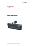
User’s Manual
Contents
1: Overview.......................................................................................................................................................................... 1
2: Terminal Specifications ................................................................................................................................. 1
2-1: Standard Specifications ....................................................................................................................................................... 1
2-2: Customer Defined Features:............................................................................................................................................... 1
3: Terminal RS232C Communication Link Details ........................................................... 2
3-1: Connection Options ..............................................................................................................................................................2
3-2: Emergency Stop Switch Operation Details ...................................................................................................................... 3
3-3: Communication Parameters ............................................................................................................................................... 3
4: Keys, LED Location, and Key Code ............................................................................................ 5
5: Terminal Display..................................................................................................................................................... 6
Appendix: LCD Character Code of Fics -RT1 .................................................................................... 7
Terminal Model Designation........................................................................................................................... 8
Specifications are subject to change without notice due to product improvements
1
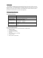
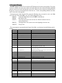
1: Overview
The Fics- RT1 is a handheld control terminal specifically designed for control of robotic systems and
automated machines. The Fics-RT1 integrates LCD display, keypad & operator safety devices into one
compact & convenient unit. Almost all features of the Fics-RT1 can be customer defined to produce a
truly dedicated control terminal for any motion control applications.
2: Terminal Specifications
2-1: Standard Specifications
Item
Keypad
Display
Emergency Stop Switch
Communication Interface
Power Supply
Working Temperature
Dimension . Weight
Cable Length
Description
(5× 8+4) mechanical key switches
4 row× 20 character LCD display
Mushroom style, push-lock type switch
RS232C/RS422, Max 19,200 bps
DC5V:
220mA max
DC12V (option):
210mA max
DC24V (option):
60mA max
08C ~ 408C
200×87×25.5 (mm)
290 (g)
2m, 5m standard
2-2: Customer Defined Features:
Customers can specify the following when ordering customer’s original terminal.
• Input power supply
• Communication protocol
• Keypad layout and definition
• Case color
• Cable (length, connector, and wiring)
• Emergency switch
• Others (contact our sales office)
2
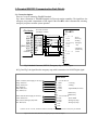
3: Terminal RS232C Communication Link Details
3-1: Connection Options
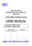
There are 3 ways of connecting Fics-RT1 terminal.
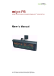
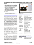
Fig.1 shows connection of Fics-RT1 terminal to Fics-series motion controllers. The signal from the
emergency stop switch is transmitted as DTR signal. If the Fics-RT1 cable is disconnected, activating
emergency stop does not affect system operation.
Fics-Series
RT1 Cable Connector
(DSUB 9pin Female)
Fics-RT1
CN1
NC 1
RXD 2
TXD 3
DTR 4
GND 5
[EMG] DSR 6
RTS 7
CTS 8
+5VOUT 9
1
2 TXD
3 RXD
4 DSR
5 GND
6 DTR
7
8
1 +5V
2 RXD
IN
3 TXD
4 DTR[EMG]
5 GND
;Power
;Receiving
;Sending
;Emergency
Stop
6 DSR
7
8
9
AWG26× 8,shield
+5V
IN
; RS422 only
; RS422 only
; Power
10 GND
11
12
13
14
Fig.1: Standard Connector, RS232C, Emergency Stop as DTR Output
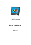
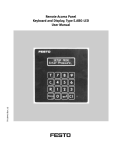
In Fig.2 and Fig.3, the signal from the emergency stop switch is transmitted as ON/OFF digital signal.
Fics-RT1
Yellow. . Red (Line) Power Supply 5V/12V OUT
Orange . Red (Line)
Orange . Black (Line)
Gray . Red (Line)
White . Black (Line)
Gray . Black (Line)
White . Red (Line) Power Supply 5V/12V OUT
Yellow . Black (Line)
Pink . Red (Line) Emergency Stop EMG
Pink . Black (Line)
1 +5V/12V/24V IN
2 RXD
; receiving
3 TXD
; sending
4 DTR
; Signal COM (for +24V)
5 GND*1
6 DSR
7
;RS422 only
;RS422 only
8
9 +5V/12V/24V IN
;Power GND
10 GND *1
11 EMG
;Emergency Stop
12 EMG
;Emergency Stop
13 NC
14 NC
*1) In the case of +5V/12V, COM and GND are internally connected. In the case of +24V, they are isolated
Fig.2: Free-end Cable, RS232C, Emergency Stop as A Direct Output
3
Fics-RT1
Yellow . Red (Line) Power Supply 5V/12V OUT
Orange .Red (Line)
Orange . Black (Line)
White . Black (Line)
Gray .Red (Line)
Gray . Black (Line)
White . Red (Line) Power Supply 5V/12V OUT
Yellow . Black (Line)
Pink .Red (Line) Emergency Stop E M G
Pink . Black (Line)
1
2
3
4
5
6
+5V/12V /24V IN
; Receiving
NC
*1
GND
NC
; Signal COM (for +24V)
; Sending
7 TXD+
8 TXD 9 +5V/12V /24V IN
*1
; Power GND
10 GND
11
; Emergency Stop
; Emergency Stop
12
13 NC
14 NC
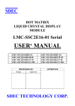
*1) In the case of +5V/12V, COM and GND are internally connected. In the case of +24V, they are isolated
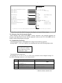
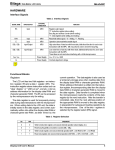
Fig.3: Free-end Cable, RS422, Emergency Stop Signal as An Open Collector Output
3-2: Emergency Stop Switch Operation Details
When emergency stop switch of Fics-RT1 is directly connected to the controlled equipment, the
emergency stop signal interacts directly with this equipment. In this case the CPU of Fics-RT1 does not
control or interact with emergency stop signal.
3-3: Communication Parameters
Communication parameters of Fics-RT1 can be changed by the following operations.
Pressing<SHIFT>, <CLR> and <MODE> keys simultaneously leads to the following display menu.
== Fics-RT1 V2.22 ==
<F1> <F2> <F3> <CLR>
NEXT CHNG SAVE QUIT
BAUD RATE = 9600
Communication stops at this point.
By operating <F1>, or <F2>, or <F3>, or <CLR> keys, parameters can be changed. Pressing <F1>
key switches the display menu to (1)~(5) as shown below.
No.
1
2
3
4
5
Parameter Name & Set Value
BAUD RATE = 9600
DATA BITS = 8
PARITY = NONE
STOP BITS = 1
KEY BREAK = CODE
Available Choices
300/600/1200/2400/4800/9600/19200
8/7
NONE/EVEN/ODD
1/2
NONE/ZERO/CODE
* Bold face indicates default value.
4
Parameter values can be chosen by pressing <F2> key.
Press <F3> key to update the parameter settings. The display menu becomes
<F1> <F2> <F3> <CLR>
YES
No
ARE YOU SURE?
YES: update parameters
No: do not update parameters
Press <CLR> to terminate
5
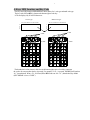
4: Keys, LED Location, and Key Code
The Keys and LED location of Fics-RT1 are shown below for 1-axis type and multi-axis type.
The key code of Fics-RT1 is shown at the bottom right of each key.
LCD can display 4 by 20 ASCII characters.
Multi-Axis Type
1-Axis Type
12345678901234567890
12345678901234567890
1
2
3
4
1
2
3
4
LCD
—Ε@LED
—Ε@LED
LED3
29
LED4
LED5
2A
2B
LED0 LED1 LED2
LED3
2C
29
LED4
LED5
2A
2B
LED0 LED1LED2
•Ô•@LED
2C
•Ô•@LED
01
09
11
19
21
01
09
11
19
21
02
0A
12
1A
22
02
0A
12
1A
22
03
0B
13
1B
23
03
0B
13
1B
23
04
0C
14
1C
24
04
0C
14
1C
24
05
0D
15
1D
25
05
0D
15
1D
25
06
0E
16
1E
26
06
0E
16
1E
26
07
0F
17
1F
27
07
0F
17
1F
27
08
10
18
20
28
08
10
18
20
28
The hexadecimal values shown in bold face at the bottom right corner of each key represents
the code to be sent out when the key is pressed. For example, if <F1> is pressed, Fics-RT1 will send out
“01” (hexadecimal). When <F1> is released, Fics-RT1 sends out “80 + 01” (hexadecimal) by default
(KEY BREAK is set as “CODE”).
6
5: Terminal Display
Fics-RT1 displays, on its LCD, the received ASCII character at the current cursor position. Every time
it receives a character, the cursor moves from left to right. When the cursor reaches the furthest right-hand
point, the cursor moves to the left-hand side of next row. When the cursor reaches the right-hand side of
the last row, it moves to the left-hand side of the first row. For the corresponding characters and their
ASCII code, refer to the Appendix.
Characters between 00h~1Fh, 80h~9Fh, except the following code, are treated as error code. When
error code XX is sent to Fics-RT1, error ‘XX’ will be displayed on LCD.
00h(RT1):
Connection Hand-Shake Code (Fics-RT1 sends 00h out)
08h(BS):
Back Space Code
0Ah(LF):
Line Feed Code (cursor moves to next row. When it reaches the last row,
cursor will not move)
0Dh(CR):
Cartridge Return Code (cursor moves to the beginning in the same row)
1Bh(ESC): Escape Code
The escape sequence, represented by the Escape Code (1Bh) + one character, has the following special
meaning.
ESC A
ESC B
ESC C
ESC D
ESC E
ESC F
ESC G
ESC H
ESC J
ESC K
ESC L
ESC M
ESC N
Cursor UP
Cursor Down
Cursor Right
Cursor Left
Clear Display & Home Cursor
Cursor On
Cursor Off
Cursor Home
Erase To End Of Screen
Erase To End Of Line
Long Bell
Erase Line
Key Brake Code
ESC O
Key Brake None
ESC P
Key Brake Zero
ESC R
ESC S
ESC T
ESC U
ESC V
ESC Y Pr Pc
Enable Cursor Blink
Disable Cursor Blink
Short Tone
Enable Key Click
Disable Key Click
Position Cursor At Pr, Pc
ESC Z
ESC [0a
ESC [1a
ESC [2a
ESC [3a
ESC [4a
ESC [5a
ESC [0b
ESC [1b
ESC [2b
ESC [3b
ESC [4b
ESC [5b
Report Device ID
LED0 ON
LED1 ON
LED2 ON
LED3 ON
LED4 ON
LED5 ON
LED0 OFF
LED1 OFF
LED2 OFF
LED3 OFF
LED4 OFF
LED5 OFF
Cursor moves 1 row up
Cursor moves 1 row down
Cursor moves 1 character right
Cursor moves 1 character left
Clear display and cursor moves to the home position
Erase from cursor position to the end of screen
Erase from cursor position to the end of line
When key is pressed generate the key code. When key is
released generate `key code`+`80h`
When key is pressed generate the key code. When key is
released do nothing
When key is pressed generate the key code. When key is
released generate `00h` code
Active buzzer with short tone
Beep when key is clicked
Disable beep when key is clicked
Cursor moves to row P r and column Pc
Row1, Col1=(20h+row position), (20h+column position)
Send Fics-RT1 identification code( ’ RT1 V2.22‘ )
ø Connection Test: send 00h to Fics-RT1, if 00h is received, then Fics-RT1 is connected.
7
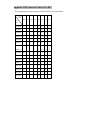
Appendix: LCD Character Code of Fics-RT1
The correspondence between characters and their ASCII code is given below.
upper
4bits
0000 0001 0010 0011 0100 0101 0110 0111
lower
4bits
xxxx0000
RT1
0
@
P
`
p
xxxx0001
!
1
A
Q
a
q
xxxx0010
“
2
B
R
b
r
xxxx0011
#
3
C
S
c
s
xxxx0100
$
4
D
T
d
t
xxxx0101
%
5
E
U
e
u
xxxx0110
&
6
F
V
f
v
xxxx0111
‘
7
G
W
g
w
(
8
H
X
h
x
)
9
I
Y
i
y
*
:
J
Z
j
z
+
;
K
[
k
{
,
<
L
¥
l
|
-
=
M
]
m
}
xxxx1110
.
>
N
^
n
xxxx1111
/
?
O
_
o
xxxx1000
BS
xxxx1001
xxxx1010
LF
xxxx1011
ESC
xxxx1100
xxxx1101
CR
8
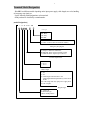
Terminal Model Designation
Fics-RT1 has different models depending on the input power supply, cable length, case color, handling
of emergency stop signal, etc.
Use the following model designation to select terminal.
OEM products are classified by terminal number.
[Model
Designation]
1 2 A D- XXX - BK
Case Type
BK: Black
GY: Gray
BU: Blue
XXX: Terminal number
(Contact our sales office for terminal number)
Emergency Stop Signal
D: Output as DTR line of RS232C
B: EMG-SW direct output (normally closed)
C: EMG-SW direct output (open collector)
External Input Power
A: DC 5V
B: DC12V
C: DC24V
Cable Length
2: 2m
5: 5m
X: Cable length other than 2m or 5m
Cable length should be specified in () at the end of
model.
For cable longer than 5m, input power supply must
be 12V or higher .
Keypad Type
1: 1-Axis type
6: Multi-axis type
Others: OEM products