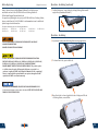
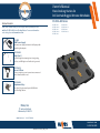
1
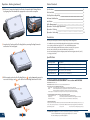
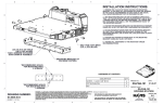
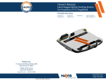
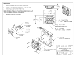
Owner’s Manual
Havis Docking Station for
Dell Latitude Rugged Extreme Notebooks
DS-DELL-400 Series
Related Products
Havis offers a wide variety of accessory products specifically for use
with the DS-DELL-400 Series Docking Station. For more information
or to order, please visit www.havis.com.
DS-DELL-401
DS-DELL-401-3
DS-DELL-402
DS-DELL-402-3
DS-DELL-403
DS-DELL-405
DS-DELL-405-3
DS-DELL-406
DS-DELL-406-3
LPS-105
90W Power Supply
External power supply and cable for Dell Laptops with
cigarette lighter adaptor.
DS-DA-102
Night Eyes II
In-vehicle night time viewing from six long lasting,
soft true, red LED lights on a flexible steel gooseneck.
DS-DA-412
Screen Stiffener
Secure your laptop screen to prevent excess wear and
reduce vibration while in use.
DS-DA-502
Replacement Keys
Set of two (2) replacement keys for DS-DELL-400
Series Docking Stations.
Havis, Inc.
75 Jacksonville Road
Warminster, PA 18974
www.havis.com
1-800-524-9900
www.havis.com
1-800-524-9900
DS-DELL-400-SERIES_OMN_9-14
Before Beginning
(Original Instructions)
Havis is pleased to provide this Owner’s Manual to aid in the proper
installation and use of the DS-DELL-400 Series Docking Station for
Dell Latitude Rugged Extreme Notebooks
For questions regarding the set-up of your DS-DELL-400 Series Docking Station,
please contact Havis at 1-800-524-9900 or visit www.havis.com for additional
product support and information.
This Owner’s Manual applies to the following Part Numbers:
DS-DELL-401
DS-DELL-402
DS-DELL-403
DS-DELL-405-3
DS-DELL-401-3
DS-DELL-402-3
DS-DELL-405
DS-DELL-406
Operation - Undocking (continued)
5) For theft deterrence, secure laptop by locking Docking Station with
supplied key (Hardware Kit Item 2).
DS-DELL-406-3
Operation - Undocking
• NEVER STOW OR MOUNT THE DOCKING STATION DIRECTLY IN A VEHICLE
AIRBAG DEPLOYMENT ZONE.
1) If previously locked, unlock Docking Station using supplied key.
• DO NOT USE COMPUTER WHILE DRIVING.
• READ ALL INSTRUCTIONS THOROUGHLY BEFORE BEGINNING INSTALLATION.
• FOR THE DS-DELL-401, DS-DELL-401-3, DS-DELL-402, DS-DELL-402-3, DS-DELL-405,
DS-DELL-405-3, DS-DELL-406, & DS-DELL-406-3 DOCKING STATIONS:
DO NOT CONNECT DIRECTLY TO VEHICLE VOLTAGE SOURCE: This product requires
a certified, automotive grade, Dell approved 90W power source rated for a
continuous, regulated 19.5VDC output (Havis Part Number LPS-105 or equivalent).
Failure to comply with this requirement will cause product damage that is NOT
repairable and is NOT covered under warranty.
2) To release Rear Hook, press in the Lock.
• FOR DOCKING STATION MODELS EQUIPPED WITH A BUNDLED POWER SUPPLY
(DS-DELL-402, DS-DELL-402-3, DS-DELL-406, DS-DELL-406-3) REFER TO THE SUPPLIED LIND
POWER SUPPLY REFERENCE GUIDE.
3) Once Rear Hook is released, grab both sides of laptop and lift out
of Docking Station, rear end first.
2
11
Operation - Docking (continued)
Table of Contents
2) With rear of computer elevated, load front of computer into Docking Station
by aligning Front Hooks with the appropriate recesses in the computer.
Specifications
Parts Included
Port Replication Capability
Antenna Identification
Installation
Cable Management
Operation - Initial Laptop Adjustment
Operation - Docking
Operation - Undocking
3
4
5
5
6
7
8
9
11
Precautions
3) Lower back of laptop onto the Docking Station, ensuring Docking Connector
and Locator Pins are aligned.
•
•
•
•
•
•
Do not place metal objects or containers of liquid on top of the Docking Station
If a malfunction occurs, immediately unplug the Power Supply and remove the laptop
Use only the specified Power Supply (Part # LPS-105) with this Docking Station
Do not store the Docking Station where water, moisture, steam, dust, etc. are present
Do not connect cables into ports other than what they are specified for
Do not leave the Docking Station in a high temperature environment (greater than 71°C, 160°F)
for a long period of time
Specifications
4) With computer seated on the Docking Station;
- apply downward pressure to
rear center of laptop and,
- pull out the Front Latching Handle until it clicks.
Power Supply Input
19.5V DC-In
Dimensions
10.8” ( 27.6 cm) H x 12.4” ( 31.5 cm ) W x 2.7” ( 6.9 cm ) D
Weight
5.25 lbs ( 2.38 kg )
Operating Environment
-29° C to 63° C ( 20° F to 145°F )
Storage Environment
-51° C to 71° C ( -60° F to 160° F )
EC DECLARATION OF CONFORMITY in accordance with EN 50498
Manufacturers Name: Havis, Inc.
Manufacturers Address: 47801 Anchor Court, Plymouth Twp, MI 48170 USA
Declares under our sole responsibility that the product:
Product name: Havis Docking Station For Dell Latitude 12 and 14 Rugged Extreme Notebooks
Model:
DS-DELL-40X, where ‘X’ may be any alphanumeric character and which describes product options.
May be followed by any alphanumeric characters which describe product options.
Product Options: This declaration covers all options of the above product which bear the CE Marking.
Push
Is in conformity with the following standards or other normative documents:
Automotive EMC Directive
EN 50498:2010, Electromagnetic compatibility (EMC) 2004/108/EC:
Product family standard for aftermarket electronic equipment in vehicles
Directive 2011/65/EU
Restriction of the use of certain hazardous substances (RoHS)
Supplementary Information:
The product herewith complies with the requirements of the Automotive EMC Directive 2004/108/EC, Annex I, 6.5, 6.6, 6.8,
and 6.9. This product requires the use of a recommended e-Marked automotive power supply when used within vehicles.
Plymouth twp, MI, USA
Pull
10
June 10, 2014 Bruce Jonik, Director of Engineering , Havis, Inc.
FCC 47CFR, Part 15 compliance: This is an FCC Class B device. Any changes or modifications
to the model DS-DELL-40X not expressly approved by Havis, Inc. could void
the user's authority to operate this equipment.
3
Parts Included
Operation - Initial Laptop Adjustment (continued)
Docking Station
3) Lower the laptop onto the Docking Station, ensuring Docking Connector and
Locator Pins are aligned. Press in the Front Hooks until each hook is secure in
the computer recess. You will hear an audible clicking noise as Front Hook
ratchets into engagement. Complete process for both Front Hooks.
Rear Fences
Strain Relief Points
Rear Hook
Locator Pins
Docking Connector
Barrel Lock
Front Hook
Release Buttons
Latching Handle
Front Hooks
4) Lastly, engage the Rear Hook by;
- applying downward pressure to rear
center of laptop and,
- pulling out the Front Latching Handle until it clicks.
Your Laptop is now secure and the Docking Station is configured to your
computer model. No further adjustments are necessary unless you switch
computer models.
Push
Mounting Bracket
Hardware Kit
This Hardware Kit includes:
1. Zip Ties (6)
2. Keys (2)
3. 1/4”-20 x 5/8” long
Button Head Screws (9)
Operation - Docking
Pull
DO NOT FORCE LAPTOP ONTO DOCKING STATION. IF THERE IS RESISTANCE,
CHECK ALIGNMENT OF COMPUTER ON DOCKING STATION.
Tools required for installation:
• 5/32” Hex Drive
(For attaching Mounting Bracket
to Motion Device with Button Head
1/4”-20 Screws)
4
1) Once Docking Station is adjusted to your computer model, ensure the Rear
Hook is released by pushing in the Lock.
9
Operation - Initial Laptop Adjustment
Port Replication Capability
Rearward Facing Ports - Advanced Port Replication
BECAUSE DOCKING STATION IS COMPATIBLE WITH MULTIPLE COMPUTER MODELS,
FAILURE TO PROPERLY ADJUST FOR YOUR SPECIFIC COMPUTER MODEL MAY
RESULT IN LOSS OF PROPER FUNCTION OR DAMAGE TO LAPTOP OR DOCKING STATION.
(DS-DELL-401, DS-DELL-401-3, DS-DELL-402, DS-DELL-402-3)
DO NOT FORCE NOTEBOOK ONTO DOCKING STATION.
IF THERE IS RESISTANCE, CHECK THE ALIGNMENT
OF NOTEBOOK ON DOCKING STATION.
Antennas
(DS-DELL-401-3,
DS-DELL-402-3)
(optional)
Power Ethernet USB 3.0 HDMI
Input
RJ45
(x3)
VGA
Serial
(x2)
Rearward Facing Ports - Basic Port Replication
(DS-DELL-405, DS-DELL-405-3, DS-DELL-406, DS-DELL-406-3)
Your notebook’s Alignment
Sockets will align with
the Docking Station’s
Locator Pins.
1) Ensure the Rear Hook is disengaged by pushing the Lock to release.
Antennas
(DS-DELL-405-3,
DS-DELL-406-3)
(optional)
Power Ethernet USB 3.0
Input
RJ45
(x3)
Forward Facing Ports (All Docking Stations)
2) Release each Front Hook individually by;
- pressing the Front Hook Release
Button and,
- pulling the Front Hook to its fullest extension.
Green LED
Indicator
(Docked)
USB 2.0
Mic /
Speaker
Antenna Identification (DS-DELL-401-3, DS-DELL-402-3, DS-DELL-405-3, DS-DELL-406-3)
Rearward Facing Antennas
8
Laptop Interface
5
Installation
Cable Management
1) Remove the Mounting Bracket from the packaging. Install the
Mounting Bracket to the Motion Device using (4) 1/4“-20 x 5/8” long
screws (Hardware Kit Item 3). Torque screws to 80 in-lbs (9.0Nm) ± 10%.
1) Orient the Docking Station in a position that is comfortable to work with.
2) Install all cables that are necessary for computing needs.
Use Zip Ties (Hardware Kit Item 1) to strain relieve cables to the Strain
Relief Points, routing all cables together to the front of the Docking Station.
3) Secure cable bundle to the Mounting Bracket with a supplied Zip Tie.
4) Create a service loop with cable bundle to ensure that no tension is on the
connectors and to enable intended motion.
5) Tie off cables onto a stationary part of the mounting system.
NOTE: Numerous hole patterns present in Mounting Bracket will accomodate Havis Motion
Devices as well as most competitors’
1/4”-20 Screws
(Mounting system not included with Docking Station)
Mounting Bracket
Use as many zip ties as
necessary to secure cables.
Typical Motion Device Example
(not included)
NOTE: We recommend applying a drop of medium strength (blue)
thread locking adhesive to the threads of all fasteners.
2) Lower the Docking Station to the Mounting Bracket as shown and secure
with (4) 1/4”-20 x 5/8” long screws (Hardware Kit Item 3). Torque screws
to 80 in-lbs (9.0 Nm) ± 10%.
This loop must be large enough
to allow full range of expected
rotation and extension without
stressing connections.
Collect cables to secure
to the mounting system
(Note: mounting system not included)
6
1/4”-20 Screws
www.havis.com • 1-800-524-9900
7
Operation - Initial Laptop Adjustment
Port Replication Capability
Rearward Facing Ports - Advanced Port Replication
BECAUSE DOCKING STATION IS COMPATIBLE WITH MULTIPLE COMPUTER MODELS,
FAILURE TO PROPERLY ADJUST FOR YOUR SPECIFIC COMPUTER MODEL MAY
RESULT IN LOSS OF PROPER FUNCTION OR DAMAGE TO LAPTOP OR DOCKING STATION.
(DS-DELL-401, DS-DELL-401-3, DS-DELL-402, DS-DELL-402-3)
DO NOT FORCE NOTEBOOK ONTO DOCKING STATION.
IF THERE IS RESISTANCE, CHECK THE ALIGNMENT
OF NOTEBOOK ON DOCKING STATION.
Antennas
(DS-DELL-401-3,
DS-DELL-402-3)
(optional)
Power Ethernet USB 3.0 HDMI
Input
RJ45
(x3)
VGA
Serial
(x2)
Rearward Facing Ports - Basic Port Replication
(DS-DELL-405, DS-DELL-405-3, DS-DELL-406, DS-DELL-406-3)
Your notebook’s Alignment
Sockets will align with
the Docking Station’s
Locator Pins.
1) Ensure the Rear Hook is disengaged by pushing the Lock to release.
Antennas
(DS-DELL-405-3,
DS-DELL-406-3)
(optional)
Power Ethernet USB 3.0
Input
RJ45
(x3)
Forward Facing Ports (All Docking Stations)
2) Release each Front Hook individually by;
- pressing the Front Hook Release
Button and,
- pulling the Front Hook to its fullest extension.
Green LED
Indicator
(Docked)
USB 2.0
Mic /
Speaker
Antenna Identification (DS-DELL-401-3, DS-DELL-402-3, DS-DELL-405-3, DS-DELL-406-3)
Rearward Facing Antennas
8
Laptop Interface
5
Parts Included
Operation - Initial Laptop Adjustment (continued)
Docking Station
3) Lower the laptop onto the Docking Station, ensuring Docking Connector and
Locator Pins are aligned. Press in the Front Hooks until each hook is secure in
the computer recess. You will hear an audible clicking noise as Front Hook
ratchets into engagement. Complete process for both Front Hooks.
Rear Fences
Strain Relief Points
Rear Hook
Locator Pins
Docking Connector
Barrel Lock
Front Hook
Release Buttons
Latching Handle
Front Hooks
4) Lastly, engage the Rear Hook by;
- applying downward pressure to rear
center of laptop and,
- pulling out the Front Latching Handle until it clicks.
Your Laptop is now secure and the Docking Station is configured to your
computer model. No further adjustments are necessary unless you switch
computer models.
Push
Mounting Bracket
Hardware Kit
This Hardware Kit includes:
1. Zip Ties (6)
2. Keys (2)
3. 1/4”-20 x 5/8” long
Button Head Screws (9)
Operation - Docking
Pull
DO NOT FORCE LAPTOP ONTO DOCKING STATION. IF THERE IS RESISTANCE,
CHECK ALIGNMENT OF COMPUTER ON DOCKING STATION.
Tools required for installation:
• 5/32” Hex Drive
(For attaching Mounting Bracket
to Motion Device with Button Head
1/4”-20 Screws)
4
1) Once Docking Station is adjusted to your computer model, ensure the Rear
Hook is released by pushing in the Lock.
9
Operation - Docking (continued)
Table of Contents
2) With rear of computer elevated, load front of computer into Docking Station
by aligning Front Hooks with the appropriate recesses in the computer.
Specifications
Parts Included
Port Replication Capability
Antenna Identification
Installation
Cable Management
Operation - Initial Laptop Adjustment
Operation - Docking
Operation - Undocking
3
4
5
5
6
7
8
9
11
Precautions
3) Lower back of laptop onto the Docking Station, ensuring Docking Connector
and Locator Pins are aligned.
•
•
•
•
•
•
Do not place metal objects or containers of liquid on top of the Docking Station
If a malfunction occurs, immediately unplug the Power Supply and remove the laptop
Use only the specified Power Supply (Part # LPS-105) with this Docking Station
Do not store the Docking Station where water, moisture, steam, dust, etc. are present
Do not connect cables into ports other than what they are specified for
Do not leave the Docking Station in a high temperature environment (greater than 71°C, 160°F)
for a long period of time
Specifications
4) With computer seated on the Docking Station;
- apply downward pressure to
rear center of laptop and,
- pull out the Front Latching Handle until it clicks.
Power Supply Input
19.5V DC-In
Dimensions
10.8” ( 27.6 cm) H x 12.4” ( 31.5 cm ) W x 2.7” ( 6.9 cm ) D
Weight
5.25 lbs ( 2.38 kg )
Operating Environment
-29° C to 63° C ( 20° F to 145°F )
Storage Environment
-51° C to 71° C ( -60° F to 160° F )
EC DECLARATION OF CONFORMITY in accordance with EN 50498
Manufacturers Name: Havis, Inc.
Manufacturers Address: 47801 Anchor Court, Plymouth Twp, MI 48170 USA
Declares under our sole responsibility that the product:
Product name: Havis Docking Station For Dell Latitude 12 and 14 Rugged Extreme Notebooks
Model:
DS-DELL-40X, where ‘X’ may be any alphanumeric character and which describes product options.
May be followed by any alphanumeric characters which describe product options.
Product Options: This declaration covers all options of the above product which bear the CE Marking.
Push
Is in conformity with the following standards or other normative documents:
Automotive EMC Directive
EN 50498:2010, Electromagnetic compatibility (EMC) 2004/108/EC:
Product family standard for aftermarket electronic equipment in vehicles
Directive 2011/65/EU
Restriction of the use of certain hazardous substances (RoHS)
Supplementary Information:
The product herewith complies with the requirements of the Automotive EMC Directive 2004/108/EC, Annex I, 6.5, 6.6, 6.8,
and 6.9. This product requires the use of a recommended e-Marked automotive power supply when used within vehicles.
Plymouth twp, MI, USA
Pull
10
June 10, 2014 Bruce Jonik, Director of Engineering , Havis, Inc.
FCC 47CFR, Part 15 compliance: This is an FCC Class B device. Any changes or modifications
to the model DS-DELL-40X not expressly approved by Havis, Inc. could void
the user's authority to operate this equipment.
3
Before Beginning
(Original Instructions)
Havis is pleased to provide this Owner’s Manual to aid in the proper
installation and use of the DS-DELL-400 Series Docking Station for
Dell Latitude Rugged Extreme Notebooks
For questions regarding the set-up of your DS-DELL-400 Series Docking Station,
please contact Havis at 1-800-524-9900 or visit www.havis.com for additional
product support and information.
This Owner’s Manual applies to the following Part Numbers:
DS-DELL-401
DS-DELL-402
DS-DELL-403
DS-DELL-405-3
DS-DELL-401-3
DS-DELL-402-3
DS-DELL-405
DS-DELL-406
Operation - Undocking (continued)
5) For theft deterrence, secure laptop by locking Docking Station with
supplied key (Hardware Kit Item 2).
DS-DELL-406-3
Operation - Undocking
• NEVER STOW OR MOUNT THE DOCKING STATION DIRECTLY IN A VEHICLE
AIRBAG DEPLOYMENT ZONE.
1) If previously locked, unlock Docking Station using supplied key.
• DO NOT USE COMPUTER WHILE DRIVING.
• READ ALL INSTRUCTIONS THOROUGHLY BEFORE BEGINNING INSTALLATION.
• FOR THE DS-DELL-401, DS-DELL-401-3, DS-DELL-402, DS-DELL-402-3, DS-DELL-405,
DS-DELL-405-3, DS-DELL-406, & DS-DELL-406-3 DOCKING STATIONS:
DO NOT CONNECT DIRECTLY TO VEHICLE VOLTAGE SOURCE: This product requires
a certified, automotive grade, Dell approved 90W power source rated for a
continuous, regulated 19.5VDC output (Havis Part Number LPS-105 or equivalent).
Failure to comply with this requirement will cause product damage that is NOT
repairable and is NOT covered under warranty.
2) To release Rear Hook, press in the Lock.
• FOR DOCKING STATION MODELS EQUIPPED WITH A BUNDLED POWER SUPPLY
(DS-DELL-402, DS-DELL-402-3, DS-DELL-406, DS-DELL-406-3) REFER TO THE SUPPLIED LIND
POWER SUPPLY REFERENCE GUIDE.
3) Once Rear Hook is released, grab both sides of laptop and lift out
of Docking Station, rear end first.
2
11
Owner’s Manual
Havis Docking Station for
Dell Latitude Rugged Extreme Notebooks
DS-DELL-400 Series
Related Products
Havis offers a wide variety of accessory products specifically for use
with the DS-DELL-400 Series Docking Station. For more information
or to order, please visit www.havis.com.
DS-DELL-401
DS-DELL-401-3
DS-DELL-402
DS-DELL-402-3
DS-DELL-403
DS-DELL-405
DS-DELL-405-3
DS-DELL-406
DS-DELL-406-3
LPS-105
90W Power Supply
External power supply and cable for Dell Laptops with
cigarette lighter adaptor.
DS-DA-102
Night Eyes II
In-vehicle night time viewing from six long lasting,
soft true, red LED lights on a flexible steel gooseneck.
DS-DA-412
Screen Stiffener
Secure your laptop screen to prevent excess wear and
reduce vibration while in use.
DS-DA-502
Replacement Keys
Set of two (2) replacement keys for DS-DELL-400
Series Docking Stations.
Havis, Inc.
75 Jacksonville Road
Warminster, PA 18974
www.havis.com
1-800-524-9900
www.havis.com
1-800-524-9900
DS-DELL-400-SERIES_OMN_9-14