1
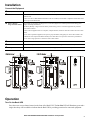
Installation Connect the Equipment Battery Connector Connect the battery. Refer to “Connect the Battery” on page 1. DSL/Modem/FAX/Phone Connect one end of a DSL/Modem/FAX/Phone cable to a telephone wall outlet and the other end to the IN port on the Back-UPS. Connect one end of a DSL/Modem/FAX/Phone cable to a modem, FAX machine or telephone and the other end to the OUT port on the Back-UPS. Battery Backup + Surge Protection outlets These outlets provide battery backup power to connected equipment for a limited period of time during power outages and voltage fluctuations. The Battery Backup + Surge Protection outlets provide battery power to connected equipment only when the Back-UPS is turned on. Connect critical equipment such as a computer, computer monitor, modem or other data sensitive devices to these outlets. Do not connect aquarium equipment, laser printers, paper shredders, sump pumps, or fans to these outlets as the modified sine wave output of the Back-UPS may cause these devices to experience a decrease in performance. Do not connect surge protectors or extension cords to these outlets. AC Power Cable Use this cable to connect the Back-UPS to AC power. Circuit breaker Use to reset the system after an overload condition has occurred causing the circuit breaker to trip. USB port To use PowerChute software, connect a USB cable (not supplied) to the PowerChute USB port. Battery Connector In Battery Connector Circuit Breaker Push to Reset bu043e Battery Backup + Surge Protection Battery Backup + Surge Protection Battery Backup + Surge Protection Circuit Breaker Push to Reset Battery Backup + Surge Protection Out PowerChute USB Port DSL/Modem/Fax/Phone In DSL/Modem/Fax/Phone Out PowerChute USB Port bu226c bu226d Operation Turn On the Back-UPS Press the POWER ON/OFF button located on the front of the Back-UPS. The On Line LED will illuminate green and a single short beep will be audible to indicate that the Back-UPS is providing protection for connected equipment. Back-UPS BX800CI-RS/BX1100CI-RS Installation and Operation 3