1
MEDIA CABINET
AVR - ASD
INSTALLATION INSTRUCTIONS
3
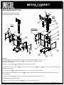
Assembly of all units is the same.
AVR9 and ASD9 have oval sides.
ASD7
7
8
1
ASD9
8
15
M8 Screws
4
9
13
14
11
6
9
15
2
12
5
Assembly:
Identify Base 2 . If you have the AVR5, 7 or 9 do not fit Column Stoppers 5 . For ASD5, 7 or 9
using columns, locate the 2 Column Stoppers 5 in the receptacles in the base to prevent
the columns hitting the floor.
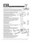
1. and 2. Fix the side panels 9 to the base using the M8 screws provided.
3. and 4. Locate the rod on the door 6 in the hole in the corner of the base 2 and Top 8 . Fix the Top to the Side Panels using
the M8 screws provided.
5. Fix the Rear Panel 11 to the Base, Side Panels and Top using the M8 screws provided.
6. If columns are being used place the columns 1 through the Top and locate them into the holes in the Base, (resting on the
column stoppers).
7. Place column adaptor 3 down the columns at the desired height and tighten grub screws.
8. See separate Instructions to fit Screen.
9. Cable up unit then press in mast inserts 7 between columns (cut-outs to rear).
DRAWN BY: Andrew Griffiths
DRAWN BY DATE: 06 December 2013
REVISION:
A-001
DRAWING NO.
Ass--20018188
SHEET 2 OF 2
SHEET NAME: INSTRUCTIONS