1
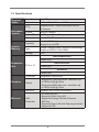
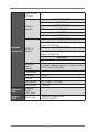
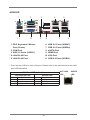
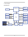
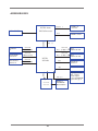
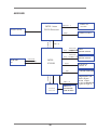
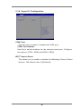
AD2550RA/U3S3
AD2550R/U3S3
AD2550R
User Manual
Version 1.0
Published Feb 2013
Copyright©2013 ASRock INC. All rights reserved.
1
Copyright Notice:
No part of this manual may be reproduced, transcribed, transmitted, or translated in
any language, in any form or by any means, except duplication of documentation by
the purchaser for backup purpose, without written consent of ASRock Inc.
Products and corporate names appearing in this manual may or may not be registered trademarks or copyrights of their respective companies, and are used only for
identiication or explanation and to the owners’ beneit, without intent to infringe.
Disclaimer:
Speciications and information contained in this manual are furnished for informational use only and subject to change without notice, and should not be constructed
as a commitment by ASRock. ASRock assumes no responsibility for any errors or
omissions that may appear in this manual.
With respect to the contents of this manual, ASRock does not provide warranty of
any kind, either expressed or implied, including but not limited to the implied warranties or conditions of merchantability or itness for a particular purpose.
In no event shall ASRock, its directors, oficers, employees, or agents be liable for
any indirect, special, incidental, or consequential damages (including damages for
loss of proits, loss of business, loss of data, interruption of business and the like),
even if ASRock has been advised of the possibility of such damages arising from
any defect or error in the manual or product.
This device complies with Part 15 of the FCC Rules. Operation is subject to the following two conditions:
(1) this device may not cause harmful interference, and
(2) this device must accept any interference received, including interference that
may cause undesired operation.
CALIFORNIA, USA ONLY
The Lithium battery adopted on this motherboard contains Perchlorate, a toxic
substance controlled in Perchlorate Best Management Practices (BMP) regulations
passed by the California Legislature. When you discard the Lithium battery in California, USA, please follow the related regulations in advance.
“Perchlorate Material-special handling may apply, see
www.dtsc.ca.gov/hazardouswaste/perchlorate”
ASRock Website: http://www.asrock.com
1
Contents
1 Introduction ....................................................... 5
1.1
1.2
1.3
1.4
1.5
Package Contents ...............................................
Speciications ......................................................
Motherboard Layout ............................................
I/O Panel .............................................................
Block Diagram .....................................................
5
6
10
16
19
2 Installation ......................................................... 22
2.1
2.2
2.3
2.4
2.5
2.6
2.7
Pre-installation Precautions ................................
Screw Holes ........................................................
Installation of Memory Modules (SO-DIMM) .......
Expansion Slots (PCI Express Slots) ..................
Onboard Headers and Connectors .....................
Driver Installation Guide .......................................
Hot Plug for Hard Disk Drives ..............................
2
22
22
23
24
25
31
32
3 UEFI SETUP UTILITY ......................................... 33
3.1 Introduction .........................................................
3.1.1 UEFI Menu Bar...........................................
3.1.2 Navigation Keys .........................................
3.2 Main Screen ........................................................
3.3 Advanced Screen ................................................
3.3.1 CPU Coniguration .....................................
3.3.2 Chipset Coniguration .................................
3.3.3 Storage Coniguration ................................
3.3.4 Super IO Coniguration...............................
3.3.5 ACPI Coniguration .....................................
3.3.6 USB Coniguration......................................
3.3.7 Voltage Control ...........................................
3.3.8 Trusted Computing .....................................
3.3.9 Serial Port Console Redirection .................
3.4 Hardware Health Event Monitoring Screen .........
3.5 Boot Screen ........................................................
3.6 Security Screen ...................................................
3.7 Exit Screen ..........................................................
33
33
34
35
36
37
38
39
41
42
44
45
46
47
48
49
51
52
4 Software Support .............................................. 53
4.1 Install Operating System .....................................
4.2 Support CD Information ......................................
4.2.1 Running Support CD ..................................
4.2.2 Drivers Menu ..............................................
4.2.3 Utilities Menu ..............................................
4.2.4 Contact Information ....................................
53
53
53
53
53
53
5 Troubleshooting ................................................ 54
5.1 Troubleshooting Procedures ............................... 54
5.2 Technical Support Procedures ............................ 56
5.3 Returning Merchandise for Service ..................... 56
3
Chapter 1: Introduction
Thank you for purchasing ASRock AD2550RA/U3S3 / AD2550R/U3S3 /
AD2550R motherboard, a reliable motherboard produced under ASRock’s
consistently stringent quality control. It delivers excellent performance with
robust design conforming to ASRock’s commitment to quality and endurance.
In this manual, chapter 1 and 2 contains the introduction of the motherboard and step-by-step hardware installation guide. Chapter 3 and 4 contains the coniguration guide of BIOS setup and information of the Support
CD.
Because the motherboard speciications and the BIOS software
might be updated, the content of this manual will be subject to
change without notice. In case any modiications of this manual
occur, the updated version will be available on ASRock’s website without further notice. You may ind the latest VGA cards
and CPU support list on ASRock’s website as well. ASRock
website http://www.asrock.com
If you require technical support related to this motherboard,
please visit our website for speciic information about the model
you are using.
www.asrock.com/support/index.asp
1.1 Package Contents
ASRock AD2550RA/U3S3 / AD2550R/U3S3 / AD2550R Motherboard
(Mini ITX Form Factor: 6.7-in x 6.7-in, 17.0 cm x 17.0 cm)
ASRock AD2550RA/U3S3 / AD2550R/U3S3 / AD2550R Quick Installation
Guide
ASRock AD2550RA/U3S3 / AD2550R/U3S3 / AD2550R Support CD
5 x Serial ATA (SATA) Data Cables (Optional)
1 x I/O Panel Shield
4
1.2 Speciications
Physical
Status
Processor
System
System
Memory
Form Factor
Mini ITX
Dimension
6.7'' x 6.7'' (17.02 cm x17.02 cm)
CPU
Supports Intel® Dual-Core Atom D2550
Processor
Socket
micro-FCBGA11
Power Phase 1+1 Power Phase Design
Chipset
Intel® ICH10R
Capacity
2 x SO-DIMM slots
Support up to 4GB
Type
Single Channel DDR3 memory technology
Supports DDR3 1066 DIMM
Voltage
1.5V
AD2550RA/U3S3
1 slots (x1)
Expansion
Slot
PCIe x 16
AD2550R/U3S3
1 slots (x1)
AD2550R
1 slots (x4)
Graphics
Ethernet
Controller
Integrated (GMA3600)
Output
- Supports D-Sub with max. resolution up
to 1920x1200 @ 60Hz
- Supports HDMI with max. resolution up
to 1920x1200 @ 60Hz
Interface
Gigabit LAN 10/100/1000 Mb/s
LAN
Controller
- 2 x Intel 82574L
- Supports Wake-On-LAN
- Supports Energy Eficient Ethernet
802.3az
- Supports Dual LAN with Teaming function
- Supports PXE
5
SATA
controller
Intel ICH10R : 5* x SATA2 3.0 Gb/s ,
support RAID 0, 1, 5, 10
(Default:5 SATA ports, w/eSATA ; Option: 6
SATA ports. wo/eSATA)
AD2550RA/U3S3
Storage
Marvell SE9172: 2 x SATA3 6.0 Gb/s
Additional
SATA
controller
AD2550R/U3S3
Marvell SE9172: 2 x SATA3 6.0 Gb/s
AD2550R
N/A
PS/2 KB/
mouse
1
VGA port
D-sub x 1 , HDMI x1
eSATA
1 (If without eSATA, the number of SATA2
ports will change from 5 to 6)
AD2550RA/U3S3
6
USB 2.0 port
AD2550R/U3S3
6
AD2550R
Rear Panel
I/O
8
AD2550RA/U3S3
Etron EJ188: 2 x USB 3.0
USB 3.0 port
AD2550R/U3S3
Etron EJ188: 2 x USB 3.0
AD2550R
N/A
Lan port
- 2 x RJ45 Gigabit Ethernet LAN ports
- LAN Ports with LED (ACT/LINK LED and
SPEED LED)
COM port
1
6
Type A USB
2.0 port
1
AD2550RA/U3S3
2 (Each support 2 USB 2.0)
USB 2.0
header
AD2550R/U3S3
2 (Each support 2 USB 2.0)
AD2550R
1 (Each support 2 USB 2.0)
AD2550RA/U3S3
Etron EJ188: 1 x USB 3.0 header (Each
support 2 USB 3.0)
Internal
Connector
USB 3.0
header
AD2550R/U3S3
Etron EJ188: 1 x USB 3.0 header (Each
support 2 USB 3.0)
AD2550R
N/A
Auxiliary
panel
header
1 (include chassis intrusion , location button
& LED , front LAN LED)
Front panel
1
Speaker
1 (4 pin)
TPM-S
1
Fan header
3 (1 x 4-pin , 2 x 3-pin)
ATX power
1 (24-pin)
Onboard
LED
Standby
PWR
LED 5vsb
1
System
BIOS
BIOS type
- 16Mb SPI Flash ROM
- AMI UEFI BIOS
7
Hardware
Monitor
Temperature
- CPU Temperature Sensing
- System Temperature Sensing
Fan
- CPU/Rear/Front Fan Tachometer
- CPU Quiet Fan (Allow Chassis Fan Speed
Auto-Adjust by CPU
Temperature)
- CPU Fan Multi-Speed Control
Voltage
Voltage Monitoring: +12V, +5V, +3V, CPU
Vcore, memory
Support OS OS
Features
Unique
Features
Microsoft® Windows® 7 / Home Server
2011 / Storage
Server 2008 R2 / Server 2008 R2 and
Fedora ( 64bit OS* no g
raphic driver support, need to use inbox
graphic driver)
- ASRock Instant Flash
- ASRock Crashless BIOS
- Boot Failure Guard (B.F.G.)
Physical
* For detailed product information, please visit our website: http://www.asrock.com
8
1.3 Motherboard Layout
AD2550RA/U3S3
1 2
3
4
5
17.0cm (6.7 in)
RoHS
AD2550RA/U3S3
CPU_FAN1
HDMI1
USB 2.0
T: USB2
B: USB3
USB 2.0
T: USB4
B: USB5
Top:
RJ-45
USB 2.0
T: USB6
B: USB7
Top:
RJ-45
6
17.0cm (6.7 in)
eSATA
FSB800
FSB800
CPU_FAN2
DDR3_A2 (64 bit, 204-pin module)
COM1
VGA1
DDR3_A1 (64 bit, 204-pin module)
USB 3.0
T: USB0
B: USB1
Ps2
Keyboard /
Mouse
1
USB3_23
Super
IO
LAN
24
LAN
CHA_FAN1
16Mb
BIOS
AUX_PANEL1
Bottom:
Optical
SPDIF
Center:
REAR SPK
Top:
Central/Bass
Bottom:
MIC IN
Center:
FRONT
Top:
LINE IN
1
CMOS
Battery
1
USB01
HD_AUDIO1
1
7
8
9
TPMS1
1
1
USB89
USB10
SATA2_4
10
SATA2_2
PLED PWRBTN
SPEAKER1
PANEL1
1
AUDIO
CODEC
1
SATA2_3
HDLED RESET
SATA2_1 SATA2_0 SATA3_1 SATA3_0
PCIE1
23 22 21
20
19 18
9
17 16
15
14 13 12 11
1
CPU Fan Connector (CPU_FAN1)
2
CPU Fan Connector (CPU_FAN2)
3
USB 3.0 Header (USB3_23, Black)
4
CPU Heatsink
5
2 x 204-pin DDR3 SO-DIMM Slots
(DDR3_A1, DDR3_A2, Black)
6
ATX Power Connector (ATXPWR1)
7
Chassis Fan Connector (CHA_FAN1)
8
USB 2.0 Header (USB01, Blue)
9
SATA2 Connector (SATA2_2, Blue)
10
SATA3 Connector (SATA3_0, White)
11
SATA3 Connector (SATA3_1, White)
12
SATA2 Connector (SATA2_0, Blue)
13
SATA2 Connector (SATA2_1, Blue)
14
SATA2 Connector (SATA2_3, Blue)
15
SATA2 Connector (SATA2_4, Blue)
16
USB 2.0 Header (USB89, Blue)
17
System Panel Header (PANEL1, White)
18
PCI Express 1.0 x16 Slot (PCIE1, Blue)
19
Vertical Type A USB (USB10)
20
Chassis Speaker Header (SPEAKER 1, White)
21
TPM-S Header (TPMS1)
22
Front Panel Audio Header (HD_AUDIO1, White)
23
Auxiliary panel header (AUX_PANEL1)
24
Intel ICH10R Chipset
10
AD2550R/U3S3
1 2
3
4
5
17.0cm (6.7 in)
RoHS
AD2550R/U3S3
CPU_FAN1
HDMI1
USB 2.0
T: USB2
B: USB3
USB 2.0
T: USB4
B: USB5
Top:
RJ-45
USB 2.0
T: USB6
B: USB7
Top:
RJ-45
LAN
6
17.0cm (6.7 in)
eSATA
FSB800
FSB800
CPU_FAN2
DDR3_A2 (64 bit, 204-pin module)
VGA1
COM1
DDR3_A1 (64 bit, 204-pin module)
USB 3.0
T: USB0
B: USB1
Ps2
Keyboard /
Mouse
1
USB3_23
Super
IO
23
LAN
CHA_FAN1
16Mb
BIOS
AUX_PANEL1
1
CMOS
Battery
1
USB01
7
8
9
TPMS1
1
1
USB89
USB10
SATA2_4
10
SATA2_2
PLED PWRBTN
SPEAKER1
PANEL1
1
1
SATA2_3
HDLED RESET
SATA2_1 SATA2_0 SATA3_1 SATA3_0
PCIE1
22
21
20
19 18
11
17 16
15
14 13 12 11
1
CPU Fan Connector (CPU_FAN1)
2
CPU Fan Connector (CPU_FAN2)
3
USB 3.0 Header (USB3_23, Black)
4
CPU Heatsink
5
2 x 204-pin DDR3 SO-DIMM Slots
(DDR3_A1, DDR3_A2, Black)
6
ATX Power Connector (ATXPWR1)
7
Chassis Fan Connector (CHA_FAN1)
8
USB 2.0 Header (USB01, Blue)
9
SATA2 Connector (SATA2_2, Blue)
10
SATA3 Connector (SATA3_0, White)
11
SATA3 Connector (SATA3_1, White)
12
SATA2 Connector (SATA2_0, Blue)
13
SATA2 Connector (SATA2_1, Blue)
14
SATA2 Connector (SATA2_3, Blue)
15
SATA2 Connector (SATA2_4, Blue)
16
USB 2.0 Header (USB89, Blue)
17
System Panel Header (PANEL1, White)
18
PCI Express 1.0 x16 Slot (PCIE1, Blue)
19
Vertical Type A USB (USB10)
20
Chassis Speaker Header (SPEAKER 1, White)
21
TPM-S Header (TPMS1)
22
Auxiliary panel header (AUX_PANEL1)
23
Intel ICH10R Chipset
12
AD2550R
1 2
3
4
17.0cm (6.7 in)
CPU_FAN1
HDMI1
USB 2.0
T: USB2
B: USB3
USB 2.0
T: USB4
B: USB5
Top:
RJ-45
USB 2.0
T: USB6
B: USB7
Top:
RJ-45
LAN
5
17.0cm (6.7 in)
eSATA
FSB800
FSB800
VGA1
COM1
CPU_FAN2
DDR3_A2 (64 bit, 204-pin module)
AD2550R
DDR3_A1 (64 bit, 204-pin module)
USB 2.0
T: USB0
B: USB1
Ps2
Keyboard /
Mouse
RoHS
Super
IO
19
LAN
CHA_FAN1
16Mb
BIOS
AUX_PANEL1
1
CMOS
Battery
7
TPMS1
1
1
USB89
USB10
SATA2_4
SATA2_2
PLED PWRBTN
SPEAKER1
PANEL1
1
1
SATA2_3
HDLED RESET
SATA2_1 SATA2_0
PCIE1
18
6
17
16
15 14
13
13 12
11
10 9 8
1
CPU Fan Connector (CPU_FAN1)
2
CPU Fan Connector (CPU_FAN2)
3
CPU Heatsink
4
2 x 204-pin DDR3 SO-DIMM Slots
(DDR3_A1, DDR3_A2, Black)
5
ATX Power Connector (ATXPWR1)
6
Chassis Fan Connector (CHA_FAN1)
7
SATA2 Connector (SATA2_2, Blue)
8
SATA2 Connector (SATA2_0, Blue)
9
SATA2 Connector (SATA2_1, Blue)
10
SATA2 Connector (SATA2_3, Blue)
11
SATA2 Connector (SATA2_4, Blue)
12
USB 2.0 Header (USB89, Blue)
13
System Panel Header (PANEL1, White)
14
PCI Express 1.0 x16 Slot (PCIE1, Blue)
15
Vertical Type A USB (USB10)
16
Chassis Speaker Header (SPEAKER 1, White)
17
TPM-S Header (TPMS1)
18
Auxiliary panel header (AUX_PANEL1)
19
Intel ICH10R Chipset
14
1.4 I/O Panel
AD2550RA/U3S3
1
2
3
4
5
6
8
7
9
10
17
16
15
14
13
1 PS/2 Keyboard / Mouse
Port (Green)
2 COM Port
3 USB 2.0 Ports (USB23)
* 4 LAN RJ-45 Port
* 5 LAN RJ-45 Port
6 Central / Bass (Orange)
7 Rear Speaker (Black)
8 Line In (Light Blue)
9 Front Speaker (Lime)
10
11
12
13
14
15
16
17
12 11
Microphone (Pink)
Optical SPDIF Out Port
USB 2.0 Ports (USB67)
USB 2.0 Ports (USB45)
eSATA Port
HDMI Port
VGA Port
USB 3.0 Ports (USB01)
* There are two LEDs on each LAN port. Please refer to the table below for the LAN
port LED indications.
LAN Port LED Indications
Activity/Link LED
Status Description
Off
No Link
Blinking Data Activity
On
100Mbps connection
Status
Off
Orange
Green
SPEED LED
Description
10Mbps connection
100Mbps connection
1Gbps connection
15
ACT/LINK
LED
SPEED
LED
LAN Port
AD2550R/U3S3
1
2
11
10
3
4
9
1 PS/2 Keyboard / Mouse
Port (Green)
2 COM Port
3 USB 2.0 Ports (USB23)
* 4 LAN RJ-45 Port
* 5 LAN RJ-45 Port
5
8
7
6
7
8
9
10
11
USB 2.0 Ports (USB67)
USB 2.0 Ports (USB45)
eSATA Port
HDMI Port
VGA Port
USB 3.0 Ports (USB01)
6
* There are two LEDs on each LAN port. Please refer to the table below for the LAN
port LED indications.
LAN Port LED Indications
Activity/Link LED
Status Description
Off
No Link
Blinking Data Activity
On
100Mbps connection
Status
Off
Orange
Green
SPEED LED
Description
10Mbps connection
100Mbps connection
1Gbps connection
16
ACT/LINK
LED
SPEED
LED
LAN Port
AD2550R
1
2
11
10
3
4
9
1 PS/2 Keyboard / Mouse
Port (Green)
2 COM Port
3 USB 2.0 Ports (USB01)
* 4 LAN RJ-45 Port
* 5 LAN RJ-45 Port
5
8
7
6
7
8
9
10
11
USB 2.0 Ports (USB67)
USB 2.0 Ports (USB54)
eSATA Port
HDMI Port
VGA Port
USB 2.0 Ports (USB01)
6
* There are two LEDs on each LAN port. Please refer to the table below for the LAN
port LED indications.
LAN Port LED Indications
Activity/Link LED
Status Description
Off
No Link
Blinking Data Activity
On
100Mbps connection
Status
Off
Orange
Green
SPEED LED
Description
10Mbps connection
100Mbps connection
1Gbps connection
17
ACT/LINK
LED
SPEED
LED
LAN Port
1.5 Block Diagram
AD2550RA/U3S3
INTEL Atom
D2550 Processor
VGA CONN
Diboofm!B
PLTRST#
EEJ1
Etron EJ188
USB 3.0 x4
QDJf!y2!Cvt
QDJf!y2!Cvt
INTEL
ICH10R
Line
In
PLTRST#
QDJf!y2!Cvt
Front
MIC
Rear
Out
Front
Out
TBUB
SPDIF
MIC
NUVOTON
ACZ_RST#
NTC6776D
18
Intel
82574L GLAN1
SATAII x5
eSATA x1
TQJ
AMI SPI 16M ROM
VTC!3/1
High-Speed USB
Rear x6 port
Front x4 port
1 port on MiniPCIE
1 port on Type A
Super I/O
Audio Codec
RTL ALC892
Intel
82574L GLAN1
RSTOUT0#
QDJf!y2!Cvt
RSTOUT1#
Cen/
Sub
HDMI CONN
RSTOUT0#
QDJf!y2!Cvt
RSTOUT1#
Front
Out
1066 MHz
ENJ!y5
RSTOUT2#
PCIE Slot
x1
Marvell 9172
SATA3 x2
DDR3 x2
RS232 x1
PS2 KB/MS
H/W Monitor
AD2550R/U3S3
INTEL Atom
D2550 Processor
VGA CONN
Diboofm!B
PLTRST#
EEJ1
QDJf!y2!Cvt
Etron EJ188
USB 3.0 x4
QDJf!y2!Cvt
Marvell 9172
SATA3 x2
QDJf!y2!Cvt
HDMI CONN
RSTOUT0#
QDJf!y2!Cvt
Intel
82574L GLAN1
RSTOUT0#
RSTOUT1#
QDJf!y2!Cvt
INTEL
ICH10R
PLTRST#
RSTOUT1#
1066 MHz
ENJ!y5
RSTOUT2#
PCIE Slot
x1
DDR3 x2
TBUB
NTC6776D
19
SATAII x5
eSATA x1
TQJ
AMI SPI 16M ROM
VTC!3/1
High-Speed USB
Rear x6 port
Front x4 port
1 port on MiniPCIE
1 port on Type A
Super I/O
NUVOTON
Intel
82574L GLAN1
RS232 x1
PS2 KB/MS
H/W Monitor
AD2550R
INTEL Atom
D2550 Processor
VGA CONN
Diboofm!B
PLTRST#
EEJ1
DDR3 x2
1066 MHz
HDMI CONN
ENJ!y5
RSTOUT0#
QDJf!y2!Cvt
Intel
82574L GLAN1
RSTOUT0#
QDJf!y2!Cvt
RSTOUT2#
QDJf!y2!Cvt
INTEL
ICH10R
PLTRST#
PCIE Slot
x4
TBUB
NTC6776D
20
SATAII x5
eSATA x1
TQJ
AMI SPI 16M ROM
VTC!3/1
High-Speed USB
Rear x6 port
Front x4 port
1 port on MiniPCIE
1 port on Type A
Super I/O
NUVOTON
Intel
82574L GLAN1
RS232 x1
PS2 KB/MS
H/W Monitor
Chapter 2: Installation
This is a Mini-ITX form factor (6.7" x 6.7", 17.0 x 17.0 cm) motherboard. Before you
install the motherboard, study the coniguration of your chassis to ensure that the
motherboard its into it.
Make sure to unplug the power cord before installing or removing the
motherboard. Failure to do so may cause physical injuries to you and
damages to motherboard components.
2.1 Screw Holes
Place screws into the holes indicated by circles to secure the motherboard to the
chassis.
Do not over-tighten the screws! Doing so may damage the motherboard.
2.2 Pre-installation Precautions
Take note of the following precautions before you install motherboard components
or change any motherboard settings.
1. Unplug the power cord from the wall socket before touching any component.
2. To avoid damaging the motherboard components due to static electricity,
NEVER place your motherboard directly on the carpet or the like. Also
remember to use a grounded wrist strap or touch a safety grounded object
before you handle components.
3. Hold components by the edges and do not touch the ICs.
4. Whenever you uninstall any component, place it on a grounded antistatic pad or
in the bag that comes with the component.
Before you install or remove any component, ensure that the power is
switched off or the power cord is detached from the power supply.
Failure to do so may cause severe damage to the motherboard, peripherals,
and/or components.
21
2.3 Installation of Memory Modules (SO-DIMM)
AD2550RA/U3S3 / AD2550R/U3S3 / AD2550R motherboard provides two 204-pin
DDR3 (Double Data Rate 3) SO-DIMM slots.
1. It is not allowed to install a DDR or DDR2 memory module into DDR3
slot; otherwise, this motherboard and SO-DIMM may be damaged.
2. Please install the memory module from DDR3_A2 slot for the irst
priority.
Installing a SO-DIMM
Please make sure to disconnect power supply before adding or
removing SO-DIMMs or the system components.
Step 1.
Step 2.
Unlock a SO-DIMM slot by pressing the retaining clips outward.
Align a SO-DIMM on the slot such that the notch on the SO-DIMM
matches the break on the slot.
The SO-DIMM only its in one correct orientation. It will cause permanent damage to the motherboard and the SO-DIMM if you force the SODIMM into the slot at incorrect orientation.
Step 3.
Firmly insert the SO-DIMM into the slot until the retaining clips at both
ends fully snap back in place and the SO-DIMM is properly seated.
22
2.4 Expansion Slots (PCI Express Slots)
There is 1 PCI Express slot on this motherboard.
PCIE slots:
AD2550RA/U3S3 / AD2550R/U3S3
PCIE1 (PCIE 1.0 x1 slot) is used for PCI Express x1 lane width cards.
AD2550R
PCIE1 (PCIE 1.0 x4 slot) is used for PCI Express x4 lane width cards.
Installing an expansion card
Step 1.
Step 2.
Step 3.
Step 4.
Step 5.
Step 6.
Before installing an expansion card, please make sure that the
power supply is switched off or the power cord is unplugged.
Please read the documentation of the expansion card and make
necessary hardware settings for the card before you start the
installation.
Remove the system unit cover (if your motherboard is already
installed in a chassis).
Remove the bracket facing the slot that you intend to use. Keep
the screws for later use.
Align the card connector with the slot and press irmly until the
card is completely seated on the slot.
Fasten the card to the chassis with screws.
Replace the system cover.
23
2.5 Onboard Headers and Connectors
Onboard headers and connectors are NOT jumpers. Do NOT
place jumper caps over these headers and connectors. Placing jumper caps over the headers and connectors will cause
permanent damage to the motherboard!
SATA2_1
(see p.10,12,14)
SATA2_4 SATA2_2
SATA2_3
Serial ATA3 Connectors
SATA3_0
SATA3_1
(see p.10,12)
Serial ATA (SATA)
Data Cable
SATA2_0
Serial ATA2 Connectors
These ive Serial ATA2
(SATA2) connectors support SATA data cables for
internal storage devices.
The current SATA2 interface
allows up to 3.0 Gb/s data
transfer rate.
These two Serial ATA3
(SATA3) connectors support SATA data cables for
internal storage devices.
The current SATA3 interface
allows up to 6.0 Gb/s data
transfer rate.
Either end of the SATA data
cable can be connected to
SATA / SATA2 / SATA3 hard
disks or the SATA2 / SATA3
connectors on this motherboard.
24
Besides two default USB
2.0 ports on the I/O panel,
there are are two USB 2.0
headers and one port on
this motherboard. Each USB
2.0 header can support two
USB 2.0 ports.
USB 2.0 Headers
and Ports
(9-pin USB0_1)
(see p.10,12)
(9-pin USB8_9)
(see p.10,12,14)
(USB6)
(see p.10,12,14)
TPMS Header
This connector supports
Trusted Platform Module
(TPM) system, which can
securely store keys, digital
certiicates, passwords, and
data. A TPM system also
helps enhance network security, protects digital identities, and ensures platform
integrity.
(17-pin TPMS1)
(see p.10,12,14)
System Panel Header
This header accommodates
several system front panel
functions.
(9-pin PANEL1)
(see p.10,12,14)
Connect the power switch, reset switch and system status indicator on the chassis to this header according to the pin assignments
below. Note the positive and negative pins before connecting the
cables.
25
PWRBTN (Power Switch):
Connect to the power switch on the chassis front panel. You may
conigure the way to turn off your system using the power switch.
RESET (Reset Switch):
Connect to the reset switch on the chassis front panel. Press the
reset switch to restart the computer if the computer freezes and
fails to perform a normal restart.
PLED (System Power LED):
Connect to the power status indicator on the chassis front panel.
The LED is on when the system is operating. The LED keeps
blinking when the sys-tem is in S1/S3 sleep state. The LED is off
when the system is in S4 sleep state or powered off (S5).
HDLED (Hard Drive Activity LED):
Connect to the hard drive activity LED on the chassis front panel.
The LED is on when the hard drive is reading or writing data.
The front panel design may differ by chassis. A front panel module mainly consists of power switch, reset switch, power LED,
hard drive activity LED, speaker and etc. When connecting your
chassis front panel module to this header, make sure the wire assignments and the pin assignments are matched correctly.
Auxiliary Panel Header
This header supports multiple functions on the front
panel, including front panel
SMB, internet status indicator and chassis intrusion pin.
(18-pin AUX_PANEL1)
(see p.10,12,14)
A. Front panel SMBus connecting pin (6-pin FPSMB)
This header allows you to connect SMBus (System Management
Bus) equipment. It can be used for communication between
peripheral equipment in the system, which has slower
transmission rates, and power management equipment.
26
B. Internet status indicator (2-pin LAN1_LED, LAN2_LED)
These two 2-pin headers allow you to use the Gigabit internet
indicator cable to connect to the LAN status indicator. When this
indicator lickers, it means that the internet is properly connected.
C. Chassis intrusion pin (4-pin CHASSIS)
This header is provided for host computer chassis with chassis
intrusion detection designs. In addition, it must also work with
external detection equipment, such as a chassis intrusion
detection sensor or a microswitch. When this function is activated,
if any chassis component movement occurs, the sensor will
immediately detect it and send a signal to this header, and the
system will then record this chassis intrusion event. The default
setting is set to the CASEOPEN and GND pin; this function is off.
D. Locator LED (6-pin LOCATOR)
This header is for the locator switch and LED on the front panel.
Speaker Header
Please connect the speaker
to this header.
(4-pin SPEAKER1)
(see p.10,12,14)
Front Panel Audio Header
This is an interface for front
(9-pin HD_AUDIO1)
panel audio cable that allows
(see p.10)
convenient connection and
control of audio devices.
1. High Deinition Audio supports Jack Sensing, but the panel wire on
the chassis must support HDA to function correctly. Please follow the
instruction in our manual and chassis manual to install your system.
2. If you use AC’97 audio panel, please install it to the front panel audio
header as below:
A. Connect Mic_IN (MIC) to MIC2_L.
B. Connect Audio_R (RIN) to OUT2_R and Audio_L (LIN) to OUT2_L.
C. Connect Ground (GND) to Ground (GND).
D. MIC_RET and OUT_RET are for HD audio panel only. You don’t
need to connect them for AC’97 audio panel.
27
CPU Fan Connectors
(4-pin CPU_FAN1)
(see p.10,12,14)
GND
+12V
CPU_FAN_SPEED
FAN_SPEED_CONTROL
Please connect the CPU fan
cable to the connector and
match the black wire to the
ground pin.
Though this motherboard provides a 4-Pin CPU fan (Quiet Fan)
connector, 3-Pin CPU fans can still work successfully even without the fan speed control function. If you plan to connect a 3-Pin
CPU fan to the CPU fan connector on this motherboard, please
connect it to Pin 1-3.
Pin 1-3 Connected
3-Pin Fan Installation
(3-pin CPU_FAN2)
(see p.10,12,14)
GND
+ 12V
CPU_ FAN_SPEED
ATX Power Connector
(24-pin ATXPWR1)
(see p.10,12,14)
12
24
1
13
Please connect an ATX power supply to this connector.
Though this motherboard provides a 24-pin ATX power connector, it can still work if you adopt a traditional
20-pin ATX power supply. To use a 20-pin ATX power
supply, please plug your power supply along Pin 1
and Pin 13.
12
24
20-Pin ATX Power Supply Installation 1
13
28
Chassis Fan Connector
(3-pin CHA_FAN1)
GND
+12V
CHA_FAN_SPEED
(see p.10,12,14)
USB 3.0 Headers
(see p.10,12)
IntA_P_D+
IntA_P_DGND
IntA_P_SSTX+
IntA_P_SSTXGND
IntA_P_SSRX+
IntA_P_SSRXVbus
ID
1
Vbus
IntA_P_SSRXIntA_P_SSRX+
GND
IntA_P_SSTXIntA_P_SSTX+
GND
IntA_P_DIntA_P_D+
29
Please connect the fan cable
to the fan connector and
match the black wire to the
ground pin.
Besides eight default USB
3.0 ports on the I/O panel,
there are two USB 3.0
header on this motherboard.
Each USB 3.0 header can
support two USB 2.0 ports.
2.6 Driver Installation Guide
To install the drivers to your system, please insert the support CD to your
optical drive irst. Then, the drivers compatible to your system can be autodetected and listed on the support CD driver page. Please follow the order
from top to bottom to install those required drivers. Therefore, the drivers
you install can work properly.
30
2.7 Hot Plug for Hard Disk Drives
This motherboard supports Hot Plug for HDDs in AHCI / RAID mode.
What is Hot Plug?
If the HDDs are NOT set for RAID, it is called “Hot Plug” for the
action to insert and remove the HDDs while the system is still
powered on and in working condition. However, please note that
it cannot perform Hot Plug if the OS has been installed into the
HDD.
31
Chapter 3: UEFI SETUP UTILITY
3.1 Introduction
This section explains how to use the UEFI SETUP UTILITY to conigure
your system. The UEFI chip on the motherboard stores the UEFI SETUP
UTILITY. You may run the UEFI SETUP UTILITY when you start up the
computer. Please press <F2> or <Del> during the Power-On-Self-Test
(POST) to enter the UEFI SETUP UTILITY, otherawise, POST will continue
with its test routines.
If you wish to enter the UEFI SETUP UTILITY after POST, restart the system by pressing <Ctl> + <Alt> + <Delete>, or by pressing the reset button
on the system chassis. You may also restart by turning the system off and
then back on.
Because the UEFI software is constantly being updated, the
following UEFI setup screens and descriptions are for reference
purpose only, and they may not exactly match what you see on
your screen.
3.1.1 UEFI Menu Bar
The top of the screen has a menu bar with the following selections:
Main
For setting system time/date information
Advanced
For advanced system conigurations
H/W Monitor Displays current hardware status
Boot
For coniguring boot settings and boot priority
Security
For security settings
Save & Exit Exit the current screen or the UEFI Setup Utility
Server Mgmt For managing the server
Event Logs For event log coniguration
32
3.1.2 Navigation Keys
Use <
> key or <
> key to choose among the selections on
the menu bar, and use <
> key or <
> key to move the cursor
up or down to select items, then press <Enter> to get into the sub
screen. You can also use the mouse to click your required item.
Please check the following table for the descriptions of each navigation
key.
Navigation Key(s)
+ / <Tab>
<PGUP>
<PGDN>
<HOME>
<END>
<F1>
<F7>
<F9>
<F10>
<F12>
<ESC>
Function Description
To change option for the selected items
Switch to next function
Go to the previous page
Go to the next page
Go to the top of the screen
Go to the bottom of the screen
To display the General Help Screen
Discard changes and exit the SETUP UTILITY
Load optimal default values for all the settings
Save changes and exit the SETUP UTILITY
Print screen
Jump to the Exit Screen or exit the current screen
33
3.2 Main Screen
When you enter the UEFI SETUP UTILITY, the Main screen will appear
and display the system overview.
34
3.3 Advanced Screen
In this section, you may set the conigurations for the following items: CPU
Configuration, Chipset Configuration, Storage Configuration, Super IO
Configuration, ACPI Configuration, USB Configuration, Voltage Control,
,Trusted Computing, and Serial Port Console Redirection.
Setting wrong values in this section may cause the system to
malfunction.
Instant Flash
Instant Flash is a UEFI lash utility embedded in Flash ROM. This
convenient UEFI update tool allows you to update system UEFI
without entering operating systems first like MS-DOS or Windows®. Just save the new UEFI ile to your USB lash drive, loppy disk or hard drive and launch this tool, then you can update
your UEFI only in a few clicks without preparing an additional
loppy diskette or other complicated lash utility. Please be noted
that the USB lash drive or hard drive must use FAT32/16/12 ile
system. If you execute Instant Flash utility, the utility will show
the UEFI iles and their respective information. Select the proper
UEFI ile to update your UEFI, and reboot your system after the
UEFI update process is completed.
35
3.3.1 CPU Coniguration
Intel Hyper Threading Technology
To enable this feature, a computer system with an Intel processor
that supports Hyper-Threading technology and an operating system that includes optimization for this technology is required. This
option will be hidden if the installed CPU does not support HyperThreading technology.
No-Execute Memory Protection
No-Execution (NX) Memory Protection Technology is an enhancement to the IA-32 Intel Architecture. An IA-32 processor with “No
Execute (NX) Memory Protection” can prevent data pages from
being used by malicious software to execute codes. This option
will be hidden if the current CPU does not support No-Excute
Memory Protection.
36
3.3.2 Chipset Coniguration
Spread Spectrum for Clockgen
Select [Disabled] for better system stability.
Restore on AC/Power Loss
This allows you to set the power state after an unexpected AC/
power loss. If [Power Off] is selected, the AC/power remains off
when the power recovers. If [Power On] is selected, the AC/power
resumes and the system starts to boot up when the power recovers.
Onboard LAN1
This allows you to enable or disable the Onboard LAN1.
Onboard LAN2
This allows you to enable or disable the Onboard LAN2.
Onboard HD Audio
Select [Auto], [Enabled] or [Disabled] for the onboard HD Audio
feature. If you select [Auto], the onboard HD Audio will be disabled
when PCI Sound Card is plugged.
Front Panel
Select [Auto] or [Disabled] for the onboard HD Audio Front Panel.
*Onboard HD Audio is designed only for AD2550RA/U3S3.
37
3.3.3 Storage Coniguration
Onboard SATAII Mode
This item is for eSATA 5 and SATA2_0 to SATA2_4 ports. Use this
to select SATA mode. Coniguration options: [IDE Mode], [AHCI
Mode], [RAID Mode] and [Disabled]. The default value is [AHCI
Mode].
AHCI (Advanced Host Controller Interface) supports NCQ and
other new features that will improve SATA disk performance but
IDE mode does not have these advantages.
Hard Disk S.M.A.R.T.
Use this to enable or disable S.M.A.R.T. (Self-Monitoring, Analysis, and Reporting Technology).
Marvell SATA3 Operation Mode
This item is for SATA3_0 and SATA3_1 ports. Use this to select Marvell SATA3 operation mode. Coniguration options: [IDE
Mode], [AHCI Mode], [RAID Mode] and [Disabled]. The default
value is [AHCI Mode].
Marvell SATA3 Bootable
Use this to enable or disable Onboard Marvell SATA3 Option
ROM. If Option ROM is disabled, you cannot use the SATA devices connected to the Marvell SATA3 controller as Boot Device.
*Marvell SATA3 Operation Mode is designed only for AD2550RA/U3S3
and AD2550RA/U3S3.
38
We recommend to use Intel® ICH10R SATA ports (SATA2_0 to
SATA2_4) for your bootable devices. This will minimum your
boot time and get the best performance. But if you still want to
boot from the Marvell SATA3 controller, you can enable it from
the UEFI.
39
3.3.4 Super IO Coniguration
COM1 Port
Use this item to enable or disable the COM1 port.
COM1 Port Address
Use this to set the address for the onboard serial port. Coniguration options: [3F8h / IRQ4] and [3E8h / IRQ4].
WDT Timeout Reset
This allows you to enable or disable the Watchdog Timeout Reset
function. The default value is [Disabled].
40
3.3.5 ACPI Coniguration
Suspend to RAM
Use this item to select whether to auto-detect or disable the Suspend-to-RAM feature. Selecting [Auto] will enable this feature if
the OS supports it.
Check Ready Bit
Use this to enable or disable Check Ready Bit.
ACPI HPET Table
Use this item to enable or disable ACPI HPET Table. The default
value is [Enabled].
Deep S5
Use this item to enable or disable the Deep S5 (Shut Down)
power saving mode.
PS/2 Keyboard Power On
Use this item to enable or disable PS/2 keyboard to turn on the
system from the power-soft-off mode.
PCI Devices Power On
Use this item to enable or disable PCI devices to turn on the system from the power-soft-off mode.
Ring-In Power On
Use this item to enable or disable Ring-In signals to turn on the
system from the power-soft-off mode.
41
RTC Alarm Power On
Use this item to enable or disable RTC (Real Time Clock) to power on the system.
USB Keyboard/Remote Power On
Use this item to enable or disable USB Keyboard/Remote to turn
on the system from the power-soft-off mode.
USB Mouse Power On
Use this item to enable or disable USB Mouse to turn on the system from the power-soft-off mode.
42
3.3.6 USB Coniguration
USB 2.0 Controller
Use this item to enable or disable the use of USB 2.0 controller.
USB 3.0 Controller
Use this item to enable or disable the use of USB 3.0 controller.
Legacy USB Support
Use this option to select legacy support for USB devices. There
are four coniguration options: [Enabled], [Auto], [Disabled] and
[UEFI Setup Only]. The default value is [Enabled]. Please refer to
below descriptions for the details of these four options:
[Enabled] - Enables support for legacy USB.
[Auto] - Enables legacy support if USB devices are connected.
[Disabled] - USB devices are not allowed to use under legacy
OS and UEFI setup when [Disabled] is selected. If you have USB
compatibility issues, it is recommended to select [Disabled] to
enter OS.
[UEFI Setup Only] - USB devices are allowed to use only under
UEFI setup and Windows / Linux OS.
Legacy USB 3.0 Support
Use this option to select legacy support for USB 3.0 devices.
*USB 3.0 Controller and Legacy USB 3.0 Support are designed only for
AD2550RA/U3S3 and AD2550R/U3S3.
43
3.3.7 Voltage Control
.
DRAM Voltage
Use this to select DRAM Voltage. The default value is [Auto].
+1.05V_CORE Voltage
Use this to select +1.05V_CORE Voltage. The default value is
[Auto].
+1.5V_ICH Voltage
Use this to select +1.5V_ICH Voltage. The default value is [Auto].
+1.1V_ICH Voltage
Use this to select +1.1V_ICH Voltage. The default value is [Auto].
44
3.3.8 Trusted Computing
TPM Support
Use this option to enable or disable BIOS support for security
devices. The default value is [Disabled].
45
3.3.9 Serial Port Console Redirection
Console Redirection
Use this option to enable or disable Console Redirection.
Console Redirection Settings
Use this option to conigure Console Redirection Settings.
46
3.4 Hardware Health Event Monitoring Screen
In this section, it allows you to monitor the status of the hardware on your
system, including the parameters of the CPU temperature, motherboard
temperature and the critical voltage.
CPU Fan 1 Setting
This allows you to set the speed of CPU fan 1. The default value
is [Full On].
CPU Fan 2 Setting
This allows you to set the speed of CPU fan 2. The default value
is [Full On].
Case Open Feature
This allows you to enable or disable the Case Open Feature. The
default value is [Enabled].
47
3.5 Boot Screen
In this section, it will display the available devices on your system for you
to conigure the boot settings and the boot priority.
Boot Option #1
Select boot option #1.
Boot Option #2
Select boot option #2.
USB Device BBS Priorities
Set the boot priorities for USB devices.
Setup Prompt Timeout
This shows the number of seconds to wait for setup activation
key. 65535(0XFFFF) means indeinite waiting.
Bootup NumLock State
If this item is set to [On], it will automatically activate the Numeric
Lock function after boot-up.
Full Screen Logo
Use this item to enable or disable OEM Logo. The default value
is [Enabled].
AddOn ROM Display
Use this option to adjust AddOn ROM Display. If you enable the
option “Full Screen Logo” but you want to see the AddOn ROM
information when the system boots, please select [Enabled]. Coniguration options: [Enabled] and [Disabled]. The default value is
[Enabled].
48
Boot From Onboard LAN
Use this item to enable or disable the Boot From Onboard LAN
feature.
49
3.6 Security Screen
In this section, you may set or change the supervisor/user password for
the system. For the user password, you may also clear it.
Secure Boot
Use this to enable or disable Secure Boot Control. The default
value is [Disabled].
50
3.7 Exit Screen
Save Changes and Exit
When you select this option, the following message “Save coniguration changes and exit setup?” will pop-out. Select [Yes] to
save the changes and exit the UEFI SETUP UTILITY.
Discard Changes and Exit
When you select this option, the following message “Discard
changes and exit setup?” will pop-out. Select [Yes] to exit the
UEFI SETUP UTILITY without saving any changes.
Discard Changes
When you select this option, the following message “Discard
changes?” will pop-out. Select [Yes] to discard all changes.
Load UEFI Defaults
Load UEFI default values for all the setup questions. F9 key can
be used for this operation.
Launch EFI Shell from ilesystem device
Attempt to Launch EFI Shell application (Shell64.ei) from one of
the available ilesystem devices.
51
Chapter 4: Software Support
4.1 Install Operating System
This motherboard supports Microsoft® Windows® Server 2003 / 2003 R2
/ 2008 / 2008 R2 / Linux compliant. Because motherboard settings and
hardware options vary, use the setup procedures in this chapter for general
reference only. Refer your OS documentation for more information.
4.2 Support CD Information
The Support CD that came with the motherboard contains necessary drivers and useful utilities that enhance the motherboard’s features.
4.2.1 Running The Support CD
To begin using the support CD, insert the CD into your CD-ROM
drive. The CD automatically displays the Main Menu if “AUTORUN”
is enabled in your computer. If the Main Menu does not appear automatically, locate and double click on the ile “ASRSETUP.EXE” in the
Support CD to display the menu.
4.2.2 Drivers Menu
The Drivers Menu shows the available device’s drivers if the system
detects installed devices. Please install the necessary drivers to activate the devices.
4.2.3 Utilities Menu
The Utilities Menu shows the application softwares that the motherboard supports. Click on a speciic item then follow the installation
wizard to install it.
4.2.4 Contact Information
If you need to contact ASRock or want to know more about ASRock,
you’re welcome to visit ASRock’s website at http://www.asrock.com;
or you may contact your dealer for further information.
52
Chapter 5: Troubleshooting
5.1 Troubleshooting Procedures
Follow the procedures below to troubleshoot your system.
Always unplug the power cord before adding, removing or changing
any hardware components. Failure to do so may cause physical
injuries to you and damages to motherboard components.
1. Disconnect the power cable and check whether the PWR LED is off.
2. Unplug all cables, connectors and remove all add-on cards from the
motherboard. Make sure that the jumpers are set to default settings.
3. Conirm that there are no short circuits between the motherboard
and the chassis.
4. Install a CPU and fan on the motherboard, then connect the chassis
speaker and power LED.
If there is no power...
1. Conirm that there are no short circuits between the motherboard
and the chassis.
2. Make sure that the jumpers are set to default settings.
3. Check the settings of the 115V/230V switch on the power supply.
4. Verify if the battery on the motherboard provides ~3VDC. Install a
new battery if it does not.
If there is no video...
1. Try replugging the monitor cables and power cord.
2. Check for memory errors.
If there are memory errors...
1. Verify that the DIMM modules are properly seated in the slots.
2. Use recommended DDR3 1600/1333/1066 ECC DIMMs.
3. If you have installed more than one DIMM modules, they should be
identical with the same brand, speed, size and chip-type.
4. Try inserting different DIMM modules into different slots to identify
53
faulty ones.
5. Check the settings of the 115V/230V switch on the power supply.
Unable to save system setup conigurations...
1. Verify if the battery on the motherboard provides ~3VDC. Install a
new battery if it does not.
2. Conirm whether your power supply provides adaquate and stable
power.
Other problems...
1. Try searching keywords related to your problem on ASRock’s FAQ
page:
http://www.asrock.com/support/faq.asp
2. Try downloading and updating the latest UEFI on ASRock’s website:
http://www.asrock.com/support/download.asp
54
5.2 Technical Support Procedures
If you have tried the troubleshooting procedures mentioned above and the
problems are still unsolved, please contact ASRock’s technical support
with the following information:
1. Your contact information
2. Model name, BIOS version and problem type.
3. System coniguration.
4. Problem description.
You may contact ASRock’s technical support at:
http://www.asrock.com/support/tsd.asp
5.3 Returning Merchandise for Service
For warranty service, the receipt or a copy of your invoice marked with the
date of purchase is required. By calling your vendor or going to our RMA
website (http://www.asrock.com/support/index.asp?cat=RMA) you may
obtain a Returned Merchandise Authorization (RMA) number.
The RMA number should be displayed on the outside of the shipping
carton which is mailed prepaid or hand-carried when you return the
motherboard to the manufacturer. Shipping and handling charges will be
applied for all orders that must be mailed when service is complete.
This warranty does not cover damages incurred in shipping or from failure
due to alteration, misuse, abuse or improper maintenance of products.
Contact your distributor irst for any product related problems during the
warranty period.
55