1
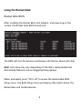
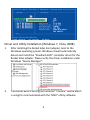
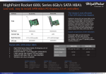
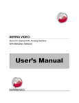
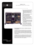
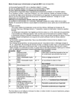
Rocket 640L/644L 6Gb/s SATA Host Adapter Quick Installation Guide v1.1 1 Contents HighPoint Rocket640L/644L....................................................................................3 Hardware Installation.............................................................................................3 Using the Rocket64xL Adapter………........................................................................4 Rocket 64xL BIOS....................................................................................................4 Driver and Utility Installation (Windows 7, Vista, 2008)..........................................5 Customer Support..................................................................................................7 Contact information...............................................................................................7 FCC Part 15 Class B Radio Frequency Interference statement..................................8 2 HighPoint Rocket 640L/644L – 4‐Port SATA 6Gb/s PCI‐E 2.0 HBA The Rocket 640L/644L SATA 6Gb/s HBA is an ideal, cost‐effective solution for adding high‐speed storage to desktop and workstation PC’s. The Rocket 640L provide 4x SATA port and the Rocket 644L provide 4x eSATA ports. The 4 independent SATA port supports up to 4 SATA 3Gb/s and 6Gb/s hard drives and SSD’s. The Rocket 640L/644L is fully backwards compatible with PCI‐E 1.0 x4, x8 and x16 slots, and supports all generations of SATA hard drives and SSD’s. Hardware Installation Installing the Rocket 64xL Host Adapter Note: Make sure the system is powered‐off before installing the Rocket 64xL host adapter. 1) Open the system chassis and locate an unused PCI‐E (2.0 or 1.0) ×4 (or x8/x16) slot. 2) Remove the PCI slot cover. 3) Gently insert the Rocket 64xL into the PCI‐E slot, and secure the bracket to the system chassis. 4) After installing the adapter, attach the hard disks or disk enclosure to the Rocket 64xL card using the SATA cables. 5) Close and secure the system chassis. 3 Using the Rocket 64xL: Rocket 64xL BIOS After installing the Rocket 64xL host adapter, and powering on the system, the Rocket 64xL BIOS should post. The BIOS will scan for devices and display information about each disk. Note: Scan time may vary depending on the disk’s make/model and disk related features such as Staggered Drive Spinup. When prompted, press “Ctrl + M” to access the Rocket 64xL BIOS Setup menu. The BIOS Setup menu will display information about the Rocket 64xL and hosted devices: 4 Driver and Utility Installation (Windows 7, Vista, 2008) 1. 3. After installing the Rocket 64xL host adapter, boot to the Windows operating system. Windows should automatically detect and install the “Standard AHCI” controller driver for the Rocket 64xL adapter. Please verify the driver installation under Windows “Device Manager”: The Rocket 64xL is coming with another “Console” device which is using for communicated with the “MSU” utility software: 5 4. 5. 6. 7. Browse to the location of the “Console” device driver and click “Next”. Driver location (Rocket 64xL Software CD): /Driver/R64xL/Windows/driver When asked: “Would you like to install this driver software?” select “Install”. Install the MSU utility. Double Click the “MSUSetup” program to install the utility. Driver location (Rocket 64xL Software CD): /Driver/R64xL/Windows/utility: After the utility is installed, please click the shortcut on the Windows desktop to run the utility. 6 Kit contents Rocket 64xL host controller Software CD Quick Installation Guide Low profile bracket Customer Support If you encounter any problems while utilizing the Rocket series host adapter, or have any questions about this or any other HighPoint Technologies, Inc. product, feel free to contact our Customer Support Department. Web Support: http://www.highpoint‐tech.com/websupport/ HighPoint Technologies, Inc. websites: http://www.highpoint‐tech.com 7 FCC Part 15 Class B Radio Frequency Interference statement This equipment has been tested and found to comply with the limits for a Class B digital device, pursuant to part 15 of the FCC Rules. These limits are designed to provide reasonable protection against harmful interference in a residential installation. This equipment generates uses and can radiate radio frequency energy and, if not installed and used in accordance with the instructions, may cause harmful interference to radio communications. However, there is no guarantee that interference will not occur in a particular installation. If this equipment does cause harmful interference to radio or television reception, which can be determined by turning the equipment off and on, the user is encouraged to try to correct the interference by one or more of the following measures: Reorient or relocate the receiving antenna. Increase the separation between the equipment and receiver. Connect the equipment into an outlet on a circuit different from that to which the receiver is connected. Consult the dealer or an experienced radio/TV technician for help. Modifications not expressly approved by the manufacturer could void the user’s authority to operate the equipment under FCC rules. This device complies with part 15 of the FCC Rules. Operation is subject to the following two conditions: (1) this device may not cause harmful interference, and (2) this device must accept any interference received, including interference that may cause undesired operation. European Union Compliance Statement This Information Technologies Equipment has been tested and found to comply with the following European directives: European Standard EN55022 (1998) Class B European Standard EN55024 (1998) 8