1
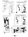
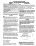
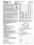
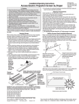
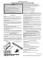
Premier by Draper Page 2 of 3 Screen Needs to Run Up More ➀ Run screen down about 1' and turn off. ➁ With the up switch on, turn the UP limit screw (II) counterclockwise (three turns of screw equals ½ roller revolution). ➂ Repeat steps 1 and 2 until desired position is reached. CAUTION: Do NOT allow the dowel to wrap up over the roller when the screen is running up! This could damage the screen. Case Dimensions 51/4" Mounting hole 113/16" Limit Adjustments (Built-in Low Voltage Motors) (Height adjustments are made from wall switch) Please Note: Screen limits are factory set for optimum performance of the screen. Any adjustment of these limits could void the warranty. Please check with Draper prior to resetting screen limits. CAUTION: Always be prepared to shut screen off manually when new adjustment is being tested. Screen may be severely damaged if viewing surface is allowed to run too far up or too far down. CAUTION: Be sure all switches are in “off” position before adjusting limit switches. To Motor ➀ Connect the switch to the motor via the terminal blocks, or via the with U Dmodular cable. C + Built-In modular port using four conductor When using modular 5V p o o Low Voltage DC w m m cable, the cable connectors MUSTn NOT be crimped in reverse, as with o n standard telephone cable. ➁ Set the slide switch to the lower position. Press and hold the DOWN button on the switch to move the viewing surface to the desired lower limit. If the screen moves in the opposite direction, To Motor To Motor release the DOWN button and press and with with Slide + Built-In UD C Built-In Switch hold down the STOP button for four seconds. Low Voltage p o o 5V Low Voltage w m DC n Back View m This will reverse the operao n tion of the UP and DOWN FUNCTION POSITION switches. Set LOWER limit DOWN 3 Move slider switch into Set UPPER limit UP center position.Wait a CENTER Normal Operation To Motor couple of seconds. with Slide Built-In Switch Please Note: If you move the slider switch Low Voltage Back View from down to up in one motion it sets the two Please Note: 5V DC must be limits in the same position. FUNCTION POSITION connected to be able to set Set LOWER limit DOWN ➃ Set the slide switch to the higher position. wall switch. Move the viewing surface to the desired upper limitsUPusingSetthe UPPER limit limit by pressing and holding the UP button on the wall switch. Normal Operation CENTER ➄ Return the slide switch to the center position to return to normal operation. ➅ To set the viewing surface to an alternate format position, move the viewing surface to the desired position and press the STOP button. Press and hold the STOP button for at least three seconds to record the position. Please Note: Pressing and releasing the UP button on the switch will move the screen to its upper limit. Pressing and releasing the DOWN button will move the screen to its lower limit. While the motor is in motion, pressing the STOP button for less than two seconds will stop the viewing surface at its present position. Once the motor is stopped, pressing the STOP button will move the viewing surface to its alternate format position. Pressing and holding the STOP button, when the motor is at rest or in motion, for at least three seconds will record a new alternate format position. 57/8" 7/8" dia. electrical connection hole 21/8" 1" 15/16" Types of Installation P OT S Wall Optional Ceiling Opening Trim Kit (Dims-Side View) Appropriate hardware provided by installer. P OT S Tab-Tension Adjustment Procedure for Premier Suspended 21/16" Appropriate hardware provided by installer. 11/16" 21/8" If using "S" Hooks )by others), be sure to crimp both ends of the "S" Hooks. 4" 63/4" Built-in Low Voltage Motor: Switch-to-Motor— Dry Contacts or Data Cable connection Please Note: 5V DC must be connected to be able to set limits using the wall switch. Back of wall switch. Motor Data Cable plugged in here Tensioning Cable UD P O W N C 5V O M M O N UP 5V COM DWN Adjustment Screw Data Cables to switches or to additional motors can be plugged into any of the three open jacks. the +5V Determine which side requires adjustment. Secure dowel with one hand. Caution: Do not touch or bend surface. Using Phillips-head screwdriver, depress spring-loaded adjustment screw (see drawing) and slowly turn clockwise to tighten tension, or counterclockwise to Dowel loosen tension. The screw adjusts in ¼ turn increments. Adjust only one increment (¼ turn). If problem is not corrected, leave screen in position for 24 hours to allow surface material to stretch into position. If problem still is not corrected, repeat steps 2 and 3. 8" www.draperinc.com (765) 987-7999 Please Note: This Splitter/Jack is located inside the motor-end endcap of your screen. To access, remove access panel from endcap. Please Note: Although both Dry Contact and Data Cable connections are shown, you should only use one connection type per motor.