1
Projector
IN5132/IN5142/IN5134/IN5134a/
IN5144/IN5144a/IN5135/IN5145
User's Manual (detailed)
Operating Guide
Thank you for purchasing this projector.
WARNING ►Before using this product, read all manuals for this product.
Be sure to read Safety Guide first. After reading them, store them in a safe
place for future reference.
About this manual
Various symbols are used in this manual. The meanings of these symbols are
described below.
WARNING This symbol indicates information that, if ignored, could possibly
result in personal injury or even death due to incorrect handling.
CAUTION This symbol indicates information that, if ignored, could possibly
result in personal injury or physical damage due to incorrect handling.
NOTICE
This entry indicates the potential for trouble.
Refer to the pages written following this symbol.
NOTE • The information in this manual is subject to change without notice.
• The manufacturer assumes no responsibility for any errors that may appear in
this manual.
• The reproduction, transfer or copy of all or any part of this document is not
permitted without express written approval.
Trademark acknowledgment
• Mac® is a registered trademark of Apple Inc.
• Windows®, DirectDraw® and Direct3D® are registered trademarks of Microsoft Corporation
in the U.S. and/or other countries.
• VESA and DDC are trademarks of the Video Electronics Standard Association.
•H
DMITM, the HDMI logo, and High-Definition Multimedia Interface are trademarks or registered
trademarks of HDMI Licensing LLC in the United States and other countries.
• Trademark PJLink is a trademark applied for trademark rights in
Japan, the United States of America and other countries and areas.
• Blu-ray DiscTM and Blu-rayTM are trademarks of Blu-ray Disc Association.
• DICOM® is the registered trademark of the National Electrical Manufacturers Association
for its standards publications relating to digital communications of medical information.
All other trademarks are the properties of their respective owners.
009-1419-02
1
Contents
Menu Items
Introduction . . . . . . . . . . . . . . . 3
Features . . . . . . . . . . . . . . . . . . . . . . . 3 EASY MENU. . . . . . . . . . . . . . . 42
Checking package contents . . . . . . . . . 3 PICTURE menu . . . . . . . . . . . . 44
Part names . . . . . . . . . . . . . . . . . . . . . 4
IMAGE menu. . . . . . . . . . . . . . 47
Projector, Control panel and Indicators,
Ports, Remote control
INPUT menu . . . . . . . . . . . . . . 50
Setting up . . . . . . . . . . . . . . . . . 7
SETUP menu. . . . . . . . . . . . . . 54
Arrangement. . . . . . . . . . . . . . . . . . . . 7
Connecting your devices. . . . . . . . . . 10 AUDIO menu . . . . . . . . . . . . . . 57
Fastening the cables
SCREEN menu. . . . . . . . . . . . . 59
Fastening the adapter cover. . . . . . . 15 OPTION menu. . . . . . . . . . . . . 65
Using the security bar and slot . . . . . 15
Connecting a power supply. . . . . . . . 16 NETWORK menu. . . . . . . . . . . 76
Remote control. . . . . . . . . . . . 17 SECURITY menu. . . . . . . . . . . 87
Installing the batteries. . . . . . . . . . . . 17 Presentation tools . . . . . . . . . 94
Using the REMOTE ID function . . . . 17 PC-LESS Presentation. . . . . . . . . . . 94
Thumbnail Mode, Full Screen Mode,
Changing the remote control signal frequency. . . . 18
Slideshow Mode, Playlist
About the remote control signal . . . . 18
Simple PC mouse & keyboard control. . . . . 19 USB Display . . . . . . . . . . . . . . . . . . 104
Starting USB Display, Right-Click menu,
Status Monitor . . . . . . . . . . . . 20
floating menu, Options window
<Only for IN5142, IN5144, IN5144a and
IN5145>
Maintenance. . . . . . . . . . . . . 108
Replacing the lamp. . . . . . . . . . . . . 108
Cleaning and replacing the air filter . 110
Other care. . . . . . . . . . . . . . . . . . . . 112
Troubleshooting . . . . . . . . . . 113
Warnings displayed on the Status Monitor. . . 113
Displaying the projector condition . . . . . . . 20
Displaying the log. . . . . . . . . . . . . . . 22
Power on/off . . . . . . . . . . . . . . 24
Turning on the power . . . . . . . . . . . . 24
Turning off the power . . . . . . . . . . . . 24
<Only for IN5142, IN5144, IN5144a and
Operating . . . . . . . . . . . . . . . . 25
IN5145>
Adjusting the volume. . . . . . . . . . . . . 25 Related messages . . . . . . . . . . . . . 113
Turning off the source image and audio temporarily. Regarding the indicator lamps . . . . 115
25
Resetting all settings. . . . . . . . . . . . 117
Selecting an input signal. . . . . . . . . . 26 Situations that may be easily mistaken for
Selecting an aspect ratio. . . . . . . . . . 27 machine defects . . . . . . . . . . . . . . . . 118
Adjusting the projector's elevator . . . . . 28
Specifications. . . . . . . . . . . . 123
Adjusting the lens . . . . . . . . . . . . . . . 29
Adjusting the zoom and focus,
Adjusting the lens position, lens memory
Using the automatic adjustment feature. . .
Adjusting the position . . . . . . . . . . . .
Correcting the distortion . . . . . . . . . .
Using the magnify feature. . . . . . . . .
Temporarily freezing the screen . . . .
Temporarily shutting the screen . . . .
PbyP. . . . . . . . . . . . . . . . . . . . . . . . .
31
31
32
35
36
36
37
<Only for IN5134a, IN5144a, IN5135 and
IN5145>
Using the menu function . . . . . . . . . . 39
2
OSD indicators
Introduction
Introduction
Features
The projector provides you with the following features:
ü T
he HDMI ports can support a variety of digital image equipment providing
you with clearer pictures.
ü The extremely bright lamp and high quality optical system fulfills the demands
of professional applications.
ü O
ptional lenses and a wide lens shift range provides you with the opportunity
to install the product wherever you want.
ü The lens shutter allows you to hide images you do not want to display to the
audience and helps you to appear more professional.
ü The wealth of I/O ports should support almost any business need.
Checking package contents
See the Contents of package section in the User’s Manual (concise). Your
projector should come with the items shown there. If any items are missing,
contact your dealer immediately.
WARNING ►Keep small parts away from children and pets. Small parts
should not be placed in the mouth. If swallowed, contact a physician immediately
for emergency treatment.
NOTE • Keep the original packing materials for future reshipment. Be sure
to use the original packing materials when moving the projector. Use special
caution with the lens.
• The projector may make a rattling sound when tilted, moved or shaken
because a flap to control the air flow inside of the projector will move. Be aware
that this is not a failure or malfunction.
3
Introduction
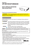
Part names
Projector
(1) Lamp cover (&108)
The lamp unit is inside.
(2)
(10)
(2) Speakers (x2) (&25, 57)
(4)
(3) Filter cover (&110)
(3)
The air filter and intake vent are inside.
(7)
(5)
(6) (2)
(8)
(4) Elevator feet (x2) (&28)
(9) (4)
(5) Elevator buttons (x2) (&28)
(15)
(6) Remote sensors (x2) (&18, 71)
(12)
(7) Lens
(8) Lens cover
(9) Indicators (&5)
(10)
(11)
(10) Intake vents
(5)
(6)
(11) Control panel (&5)
(1)
(12) S
tatus Monitor (&20)
(13)
<Only for IN5142, IN5144, IN5144a and
IN5145>
(13) AC IN (AC inlet) (&16)
(14) Exhaust vents
(15) Ports (&5)
(16) Security bar (&15)
(17) Security slot (&15)
(18) Grip (&below)
(19) Safety bar (&15)
(17)
(19)
(16)
(18)
(14)
(10)
WARNING ►Do not open or remove any portion of the product, unless
directed to do so by the manuals.
Grip
►Do not subject the projector to unstable conditions.
►Do not apply shock or pressure to this product. Place
your hands on the grip on the bottom of the projector when
carrying the projector. Remove all the attachments from
the projector, including the power cord and cables, before
carrying the projector.
►Do not look into the lens or the openings on the projector while the lamp is on.
CAUTION ►Do not touch around the lamp cover and the exhaust
vents during use or just after use, since it is too hot.
►Do not attach anything onto the lens except the projector's lens cover
because it could damage or melt the lens.
(continued on next page)
4
Introduction
Part names (continued)
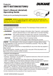
Control panel and Indicators
(9) (10) (11) (12) (13) (14)
(1) STANDBY/ON button (&24)
(2) INPUT button (&26, 39)
(3) MENU button (&39)
(4) LENS SHIFT button (&29)
(5) ZOOM button (&29)
(6) FOCUS - / + buttons (&29)
(7) SHUTTER button (&36)
(3)
(8) FUNCTION button (&22, 29)
(4)
(9) FILTER indicator (&117)
(10) SHUTTER indicator (&36)
(6)
(11) SECURITY indicator (&93)
(2)
(12) LAMP indicator (&115, 116)
(13) TEMP indicator (&115, 116)
(14) POWER indicator (&24, 115, 116)
(5)
(8)
(1)
(7)
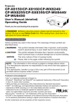
Ports (&10 ~ 14)
(1) COMPUTER IN1 port
(2) COMPUTER IN2 ports
(G/Y, B/Cb/Pb, R/Cr/Pr, H, V)
(3) LAN port
(4) USB TYPE A ports
(5) USB TYPE B port
(6) HDMI 1 port
(7) HDMI 2 port
(8) COMPONENT ports
(Y,Cb/Pb, Cr/Pr)
(9) S-VIDEO port
(10) VIDEO port
(11) AUDIO IN1 port
(12) AUDIO IN2 port
(13) AUDIO IN3 (L, R) ports
(14) AUDIO OUT (L, R) ports
(15) MONITOR OUT port
(16) REMOTE CONTROL IN port
(17) REMOTE CONTROL OUT port
(18) CONTROL port
(5) (6) (10) (7)
(4)
(2)
(3)
(1)
(9)
(18)
(16)
(continued on next page)
(17) (14)
(8) (13) (12) (11) (15)
5
Introduction
Part names (continued)
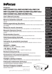
Remote control
(1) STANDBY button (&24)
(1)
(3)
(2) ON button (&24)
(3) ID - 1 / 2 / 3 / 4 buttons (&17)
(4)
(7)
(4) COMPUTER 1 button (&26)
(8)
(5) COMPUTER 2 button (&26)
(10)
(6) COMPUTER 3 button *
(13)
(7) LAN button (&26)
(14)
(8) USB TYPE A button (&26)
(16)
(9) USB TYPE B button (&26)
(10) COMPONENT button (&26)
(26)
(17)
(11) S-VIDEO button (&26)
(18)
(12) VIDEO button (&26)
(13) HDMI 1 button (&26)
(19)
(14) HDMI 2 button (&26)
(27)
(15) DIGITAL button *
(20)
(32)
(16) PAGE UP / PAGE DOWN buttons (&19, 96)
(30)
(17) F5 button (&18, 19)
(31)
(18) ENTER button (&19, 22, 39)
(19) RESET button (&39)
(20) ESC button (&19, 39)
(21) ▲/▼/◄/►cursor buttons
(22) MENU button (&39)
(34) (36)
(23) VOL + / - buttons (&25)
(35)
(24) AV MUTE button (&25)
(25) MAGNIFY ON / OFF buttons (&35)
(26) FREEZE button (&36)
(27) PbyP button ○ (&37)
(28) ASPECT button (&27)
(29) AUTO button (&31)
(30) POSITION button (&30, 31, 40)
(31) KEYSTONE button (&32)
(32) MY BUTTON - 1, 2, 3, 4 buttons (&68)
(37)
(33) LENS SHIFT button (&29)
(34) LENS MEMORY button (&30)
Back of
(35) FOCUS + / - buttons (&29)
the remote control
(36) ZOOM + / - buttons (&29)
(37) Battery cover (&17) (38) Wired remote control port (&14) (38)
(2)
(5)
(6)
(9)
(11)
(12)
(15)
(23)
(25)
(24)
(21)
(22)
(28)
(29)
(33)
NOTE • Any button marked with “*” is not supported on this projector (&114).
• Any button marked with “○” is only available for IN5134a, IN5144a, IN5135 and IN5145.
• Each time you press a button (except for the ID buttons), the ID button associated
with the current selected ID number will light (&17).
6
Setting up
Setting up
Install the projector appropriately for your environment and mounting situation.
When installing in a special application such as for ceiling mount application,
additional mounting accessories (&Specifications in the User’s Manual
(concise)) and service may be required. Before installing the projector, contact
your dealer about your application.
Arrangement
Besides the following, refer to tables T-1 to T-5 at the back of the User's Manual
(concise) to determine screen size and projection distance. The values shown in
the table are calculated for a full size screen.
Projector top
Projector bottom
Ⓗ × Ⓥ : Screen size
ⓐ : Projection distance
(from the front of the projector unit)
ⓑ , ⓒ : Screen height
(continued on next page)
7
Setting up
Arrangement (continued)
WARNING ►Install the projector where you can access the power
outlet easily. If something unusual occurs, unplug the projector immediately.
Otherwise a fire or electric shock may occur.
►Do not subject the projector to unstable conditions. If the projector falls or
topples over, it could result in injury or damage the projector and other nearby
items. Using a damaged projector could result in a fire and an electric shock.
• Do not place the projector in unstable places, such as an inclined surface,
places subject to vibration, on top of a wobbly table or cart, or a surface that is
smaller than the projector.
• Do not position the projector on its side, front or rear.
• Do not attach or place anything on the projector unless specified in this
manual.
• Do not use any mounting accessories except those specified by the
manufacturer. Read and keep the all accessory manuals.
• For special applications such as ceiling mount applications, contact your dealer
beforehand.
• IN5142, IN5144, IN5144a and IN5145 only: The projector can be installed in
any direction with appropriate mounting accessories. Contact your dealer about
such a situation.
• Place your hands on the grip on the bottom of the projector when carrying the
projector. Remove all the attachments from the projector, including the power
cord and cables, before carrying the projector.
►Do not install the projector near thermally conductive or flammable
items. Such items when heated by the projector could result in a fire and burns.
• Do not place the projector on a metal stand.
►Do not place the projector where any oils, such as cooking or machine
oil, are used. Oil may harm the product, resulting in malfunction, or falling from
the mounted position.
►Do not place the projector in a place where it may get wet. Getting the
projector wet or inserting liquid into the projector could cause a fire or electric
shock, and damage the projector.
• Do not place the projector near water, such as in a bathroom, kitchen, or
poolside.
• Do not place the projector outdoors or by the window.
• Do not place anything containing liquid near the projector.
(continued on next page)
8
Setting up
Arrangement (continued)
CAUTION ►Place the projector in a cool place with sufficient
ventilation. The projector may shutdown automatically or may malfunction if its
internal temperature is too high.
• Using a damaged projector could result in a fire and an electric shock.
• Do not place the projector in direct sunlight or near hot objects such as heaters.
• Do not place the projector where the air from an air conditioner or similar unit
will blow on it directly.
• Keep a space of 30 cm or more between the side of the projector and other
objects such as walls.
• Do not place the projector on carpet, cushions or bedding.
• Do not plug, block or cover the projector's ventilation holes. Do not place
anything around the projector that could be sucked in or stick to the projector's
intake vents.
• Do not place the projector where it can be exposed to magnetic fields. Doing
so can cause the cooling fans inside the projector to malfunction.
►Avoid placing the projector in smoky, humid or dusty places. Placing
the projector in such places could cause a fire, an electric shock and projector
malfunction.
• Do not place the projector near humidifiers. In particular, ultrasonic humidifiers
atomize chlorine and minerals from the tap water and can leave deposits inside
the projector causing image degradation and other problems.
• Do not place the projector in a smoking area, kitchen, passageway or by a
window.
NOTICE • Position the projector to prevent light from directly hitting the
projector's remote sensor.
• Do not place the product in a place where radio interference may be caused.
• Set the ALTITUDE of the SERVICE item in the OPTION menu correctly. We
recommend leaving it set to AUTO under normal circumstances (&69). If the
projector is used with a wrong setting, it may damage the projector itself or the
parts inside.
• Keep heat-sensitive items away from the projector. Otherwise, they may be
damaged by the heat from the projector.
9
Setting up
Connecting your devices
Before connecting the projector to a device, consult the device manual to
confirm that the device is compatible with this projector and prepare the required
accessories, such as appropriate cables. Contact your dealer when the required
accessory did not come with the product or an accessory is damaged.
After verifying that the projector and the devices are turned off, make all
connections per the following instructions. Refer to the illustrations on the
subsequent pages. Before connecting the projector to a network system, be sure
to read Network Guide too.
►Use only compatible accessories. Otherwise a fire or damage may occur to
the projector and devices.
WARNING • Only use accessories specified and recommended by the
projector’s manufacturer. Some regulations may apply.
• Do not disassemble or modify the projector or its accessories.
• Do not use damaged accessories. Be careful not to damage the accessories.
Route cables so that they cannot be stepped on or pinched.
►For a cable with a core at only one end, connect the end with the core to
the projector. That may be required by EMI regulations.
• CAUTION Do not turn the projector on or off while connected to a device
in operation, unless specified by the device manual. Otherwise a device or
projector malfunction may occur.
NOTE • Some input port functions can be selected based on your usage
requirements. Check the reference page indicated beside each port in the
following illustration.
• Be careful not connect a connector to a wrong port. Otherwise a device or
projector malfunction may occur.
- When connecting a connector to a port, make sure that the shape of the
connector fits the port.
-T
ighten the screws to connect a connector equipped with screws to a port.
- Use cables with straight plugs, not L-shaped ones, as the input ports of the
projector are recessed.
About Plug-and-Play capability
• Plug-and-Play is a system composed of a computer, its operating system
and peripheral equipment (i.e. display devices). This projector is VESA DDC
2B compatible. Plug-and-Play can be used by connecting this projector to a
computer that is VESA DDC (display data channel) compatible.
- Take advantage of this feature by connecting a computer cable to the
COMPUTER IN1 port (DDC 2B compatible). Plug-and-Play may not work
properly if any other type of connection is attempted.
- Use standard drivers in your computer as this projector is a Plug-and-Play
monitor.
(continued on next page)
10
Setting up
Connecting your devices (continued)
(&26, 104)
(&26)
(&57)
(&26)
Computer
NOTE • Before connecting the projector to a computer, consult the computer’s
manual and check the signal compatibility, synchronization methods and the
display resolution output to the projector.
- Some signals may need an adapter to input to this projector.
- Some computers have multiple screen display modes which may include
some signals which are not compatible with this projector.
- Although the projector can display signals with a resolution up to UXGA
(1600x1200) or up to WUXGA (1920x1200) for the IN5135 and IN5145,
the signal will be converted to the projector’s native resolution before being
displayed. The best display performance will be achieved if the resolutions of
the input signal and the projector's native resolution are identical.
• If you connect this projector to a notebook computer, you must output the
display to the projector, or output simultaneously to the computer's internal
display and the projector. Contact the computer's manual for the settings.
• Depending on the input signal, the projector's automatic adjustment function
may take time and may not operate correctly.
- Note: A composite sync signal or sync-on-green signal may confuse the
projector's automatic adjustment function (&52).
- If the automatic adjustment function does not work correctly, you may not see
the dialog to set the display resolution. In this case, use an external display
device. You may be able to see the dialog and set an appropriate display
resolution.
(continued on next page)
11
Setting up
Connecting your devices (continued)
(&76) (&19)
Computer
External
device
Access
point
(&76)
USB
wireless
adapter
(optional)
(&76)
USB
storage
device
(&94, 104)
WARNING ►Heat may build up in the USB wireless adapter. To avoid possible burns, disconnect the projector power cord for 10 minutes before touching
the adapter.
►When using the USB wireless adapter, be sure to connect the adapter to the USB
TYPE A port furthest from the LAN port and use the supplied adapter cover (&15).
CAUTION ► Before connecting the projector to a network system be sure
to obtain the network administrator's approval.
►Do not connect the LAN port to any network that might have excessive voltage.
►The designated USB wireless adapter that is sold as an option is required to use
the wireless network function of this projector. Before connecting the USB wireless
adapter, turn off the projector's power and disconnect the power cord. Do not use
any extension cable or device when connecting the adapter to the projector.
►Before removing the USB storage device from the port of the projector, be sure
to use the REMOVE USB function on the Thumbnail screen to protect your data
(&97).
►To connect both the LAN cable and USB device to the projector, only use the
USB TYPE A port furthest from the LAN port or a LAN cable that is flat on the
side where the plug’s wire is visible. Otherwise, both of them cannot be connected correctly, or a wire may break causing a malfunction.
NOTE • If an oversized USB storage device blocks the LAN port, only use the
USB TYPE A port furthest from the LAN port or use a USB extension cable to
connect the USB storage device.
12
(continued on next page)
Setting up
Connecting your devices (continued)
(&57)
(&26)
(&26)
(&26, 52)
VCR/DVD/
Blu-ray DiscTM
player
NOTE • The HDMI ports of this model are compatible with HDCP (High-bandwidth Digital Content Protection) and therefore capable of displaying video
signals from HDCP compatible DVD players and the like.
- The HDMI ports support the following signals:
Video signal : 480i@60, 480p@60, 576i@50, 576p@50, 720p@50/60,
1080i@50/60, 1080p@50/60
Audio signal : Format Linear PCM
Sampling frequency 48kHz / 44.1kHz / 32kHz
- This projector can be connected with other HDMITM compatible equipment, but
some equipment may not be compatible with the projector and may not work
properly (for example, no video being displayed).
- Be sure to use an HDMITM cable that has the HDMITM logo.
- Use a Category 2-certified HDMITM cable to input a 1080p@50/60 signal to
the projector.
- When the projector is connected with a device with a DVI connector, use a
DVI to HDMITM cable to connect to the HDMITM input.
• The HDMITM cables may become disconnected easily because there are no
mechanical locks on the cables or connectors. We recommend fastening the
cables to the projector to prevent the cables from coming off (&14).
(continued on next page)
13
Setting up
Connecting your devices (continued)
Another
projector
Speakers
(with an amplifier)
(&56) Monitor
(Wired)
Remote
control
NOTE • To use a wired remote control, connect a wired remote control to the
REMOTE CONTROL IN port. You can also connect another projector to the
REMOTE CONTROL OUT port to control it from the wired remote control. You
can use this projector as a remote control-relay with the REMOTE CONTROL
IN and OUT ports. To connect the wired remote control or another projector
to the REMOTE CONTROL IN or OUT ports, use audio cables with 3.5 mm
diameter stereo mini plugs. This function is useful when a wireless remote
signal cannot reliably reach the projector.
Fastening the cables
To tie the signal cables and prevent them
from coming off, fasten them to the projector
using commercially available plastic cable
ties. Use a cable tie 2.0 x 5.0mm or smaller.
We recommend curling the end of the tie
slightly before you thread it to the tie holder,
so that you can get it through easily.
Tie holder
Cable tie
WARNING ►Do not bind the power cord.
CAUTION ►Only use plastic ties to fasten the cables. A metal tie may
damage the cables and tie holder.
►Do not bind the cables too tightly. The cables or the hole may be damaged.
14
Setting up
Fastening the adapter cover
When using the USB wireless adapter, be
sure to connect the adapter to the USB
TYPE A port furthest from the LAN port
and use the supplied adapter cover.
1.
2.
3.
Tab
1
Loosen the screw (marked with a
triangle) on the bottom left of the
USB TYPE A ports.
Insert the cover tab into the hole at
the upper right of the USB TYPE A
ports in the direction of the arrow.
Align the screw holes on the projector and the cover. Then
insert the screw removed from the projector into the hole
and tighten the screw.
2
3
WARNING ►Keep small parts away from children and pets. Do not to put
them in the mouth.
►Heat may build up in the USB wireless adapter. To avoid possible burns
disconnect the projector power cord for 10 minutes before touching the adapter.
Security slot
Using the security bar and slot
A commercially available anti-theft cable
can be attached to the security bar on the
projector. Refer to the illustration to choose
an anti-theft cable.
This product also has a security slot for a
Kensington lock.
For details, see the security tool manual.
11mm
Anti-theft
cable
19mm
15mm
security bar
WARNING ►Do not use the security bars and slot to prevent the projector
from falling down, since this is not what it was designed for.
CAUTION ►Do not place the anti-theft cable near the exhaust vents since
they may may become too hot.
NOTE • The security bar and slot cannot prevent all thefts. They are intended
to deter thefts.
• The safety bar (&4) can be used like the security bar.
15
Setting up
Connecting a power supply
the power cord into the projector's AC
1. Plug
IN (AC inlet).
plug the power cord’s plug into a
2. Firmly
power outlet. After a few seconds, the
AC IN
Power
cord
POWER indicator will light steady orange.
Remember that when the DIRECT POWER ON
function activated (&66), the power supply connection
will make the projector turn on.
WARNING ►Do not connect the projector to a power supply when no lens
unit is attached to it.
►Use extra caution when connecting the power cord, as incorrect or faulty
connections may result in fire and/or electrical shock.
• Do not touch the power cord with a wet hand.
• Only use the power cord that came with the projector. If it is damaged, contact
your dealer to get a new one. Never modify the power cord.
• Only plug the power cord into an outlet whose voltage is matched with the
power cord. The power outlet should be close to the projector and easily
accessible. Remove the power cord for complete separation.
• Do not distribute the power supply to multiple devices. Doing so may overload
the outlet and connectors, loosen the connection, or result in fire, electric shock
or other accidents.
• Connect the ground terminal for the AC inlet of this unit to the ground terminal
of the building using an appropriate power cord (bundled).
NOTICE • This product is also designed for IT power systems with a phasetophase voltage of 220 to 240 V.
16
Remote control
Remote control
Installing the batteries
Insert batteries into the remote control before using it (batteries not included). If
the remote control starts to malfunction, try replacing the batteries. If the remote
control will not be used for a long period, remove the batteries from the remote
control and store them in a safe place.
1
2
Holding the hook part of the battery
cover, remove it.
Align and insert two AA batteries (HITACHI
MAXELL or HITACHI MAXELL ENERGY,
3
Part No.LR6 or R6P - not included)
according to their plus and minus terminals
as indicated in the remote control.
Replace the battery cover in the direction of the arrow
and snap it back into place.
1.
2.
3.
WARNING ►Always handle batteries with care and use them only as directed.
Improper use may result in battery explosion, cracking or leakage, which could result
in fire, injury and/or pollution of the surrounding environment.
• Be sure to use only the batteries specified. Do not use batteries of different types
simultaneously. Do not mix new and used batteries.
• Make sure the plus and minus terminals are correctly aligned when loading batteries.
• Keep batteries away from children and pets.
• Do not recharge, short circuit, solder or disassemble batteries.
• Do not place batteries fire or water. Keep batteries in a dark, cool and dry place.
• If you observe battery leakage, wipe out the leakage and then replace batteries.
If the leakage adheres to your body or clothes, rinse well with water immediately.
• Obey the local laws on disposing batteries.
Using the REMOTE ID function
Utilize this function to control specific projectors with the
remote control by assigning ID numbers to multiple projectors
of the same type simultaneously.
Assign an ID number to each projector before using the
REMOTE ID item in the SERVICE menu of the OPTION
menu (71). Press the ID button with the same ID number
as assigned to the projector you are going to control. The ID
button selected will light for several seconds.
ID buttons
NOTE • Each time you press a button (other than an ID button), the ID button
associated with the currently selected ID number will light.
• To confirm a projector's current ID, press any ID button for 3 seconds. The
projector's ID will display on the screen regardless of which ID button is
pressed.
17
Remote control
Changing the remote control signal frequency
There are two choices to control the signal frequency mode of the remote control,
Mode 1:NORMAL and Mode 2:HIGH. If the remote control does not function
properly, try changing its mode.
In order to set the Mode, press and hold the two button combination listed below
for about 3 seconds.
(1) To set Mode 1:NORMAL
AV MUTE and ZOOM buttons
(2) To set Mode 2:HIGH
.F5 and KEYSTONE buttons
(2)
F5 button
KEYSTONE
button
(1)
AV MUTE
button
ZOOM button
Remember to use the same mode
for the projector's REMOTE FREQ. in the SERVICE item of the OPTION menu
(71).
About the remote control signal
The remote control works with the
projector’s remote sensors. This
30° 30°
projector has two remote sensors on the
front and back sides.
The sensors can sense signals within
the following range:
60 degrees (30 degrees to the left and right of the
sensor) within approximately 3 meters.
3m
30° 30° 3m
(approx.)
NOTE • You can deactivate one of the sensors using the REMOTE RECEIV.
item in the SERVICE menu of the OPTION menu (71).
• The remote control signal may be able to be reflected off of the screen or
other item. If it is difficult to send the signal to the sensor directly, try reflecting
the signal.
• The remote control uses infrared light to send signals to the projector (Class 1
LED), so be sure to use the remote control in an area free from obstacles that
could block the remote control’s signal to the projector.
• The remote control may not work correctly if strong light (such as direct
sun light) or light from an extremely close range (such as from an inverter
fluorescent lamp) shines on the remote sensor of the projector. Adjust the
position of projector avoiding those lights.
18
Remote control
Simple PC mouse & keyboard control
When the projector’s USB TYPE B port and the
computer’s type A USB port are connected and
MOUSE is selected for the USB TYPE B item in the
OPTION menu (67), the remote control will work
like a simple PC mouse and keyboard.
(1) PAGE UP key: Press the PAGE UP button.
(2) PAGE DOWN key: Press the PAGE DOWN button.
(3) Mouse left button: Press the ENTER button.
(1)
(4) Move pointer: Use the cursor buttons
▲, ▼, ◄ and ►.
(2)
(5) ESC key: Press the ESC button.
(7)
(6) Mouse right button: Press the RESET button.
(7) F5 key: Press the F5 button.
NOTICE ►Improper use of the simple mouse &
keyboard function could damage your equipment.
When using this function, connect this product only
to a computer. Be sure to check your computer’s
manuals before connecting this product to a
computer.
USB TYPE B
port
(3)
(4)
(6)
(5)
NOTE • When the simple mouse & keyboard function of this product does not
work correctly, check the following:
• When a USB cable connects this projector with a computer having a built-in
pointing device (e.g. track ball) like a laptop PC, open BIOS setup menu, then
select the external mouse and disable the built-in pointing device, because the
built-in pointing device may have priority to this function.
• Windows 95 OSR 2.1 or higher is required for this function. This function may not
work depending on the computer’s configurations and mouse drivers. This function can
work with computers that use a standard USB mouse or keyboard.
• Pressing two buttons at once will not work (for instance, you cannot press two
buttons simultaneously to move the mouse pointer diagonally).
• This function is only activate when the projector is working properly. This
function is unavailable:
- When the lamp is warming up. (The POWER indicator blinks green.)
- When either USB TYPE A or USB TYPE B is the selected input source.
- While displaying BLANK (59), TEMPLATE (63) or MY IMAGE (84)
screen.
- When any menu is displayed on the screen.
- When the cursor buttons are being used to operate the sound or screen
functions such as adjusting the sound volume, correcting the keystone,
correcting the picture position and magnifying the screen.
19
Status Monitor <Only for IN5142, IN5144, IN5144a and IN5145>
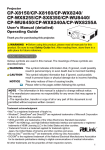
Status Monitor
<IN5142, IN5144, IN5144a and IN5145 only>
The Status Monitor is the LCD window on the rear
panel of the IN5142, IN5144, IN5144a and IN5145.
The Status Monitor displays the projector's present
condition, including errors, setup information and error
history.
Status Monitor
Displaying the projector condition
If no buttons are being operated, the Status Monitor will display the projector's
condition as per below.
NOTE • If the STANDBY MODE item of SETUP menu is set to SAVING (56),
the Status Monitor displays nothing while the projector is in standby mode.
• When INSTALLATION in the SETUP menu is set to FRONT / CEILING or REAR /
CEILING, the Status Monitor contents are displayed upside down (55).
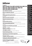
In a normal state
The Status Monitor displays the state of the projector
in three lines.
1st line : Displays the projector condition. While the
lamp is on, the selected port is displayed.
Displayed conditions are:
STANDBY: The projector is in standby mode.
WARM UP: The projector is warming up.
SEARCHING: The projector is searching an input signal.
COOL DOWN: The projector is cooling down.
2nd line
S T ANDBY
# 1 2 3 4 5 6 7 8 9 0 AB
23°C
example
: While the lamp is on, the detected input signal condition is
displayed. Otherwise, the projector's serial number is displayed.
Displayed conditions are:
SYNC OUT: Detected input signal is out of specified range.
NO SIGNAL: There is no input signal.
CONNECTED: The LAN or USB TYPE B port is selected, the projector is
connected to the network (or the computer) and an image is being transferred
to the projector.
HOLD: The LAN port is selected and the projector is connected to the network
but no image is transferred.
NOT CONNECTED: The LAN or USB TYPE B port is selected, but the
projector is not connected to the network or the computer.
(continued on next page)
20
Status Monitor <Only for IN5142, IN5144, IN5144a and IN5145>
Displaying the projector condition (continued)
: When the lamp is on, it displays the supplied voltage and
3rd line peripheral Celsius temperature.
NOTE • Nothing is displayed on the 2nd line of the monitor, when the projector
is searching for an input signal and when the USB TYPE A ports are set to
normal condition.
• "NO SIGNAL" is displayed on the 2nd line of the monitor (67) when the
USB TYPE B port is selected.
• The displayed temperature might differ from the actual peripheral temperature
because the displayed temperature is measured inside of the projector.
Error states:
The Status Monitor displays error warnings in capital
letters. To resolve the errors, refer to the sections
"Related messages" (114) and "Regarding the
indicator lamps" (115, 116).
Displayed warnings:
COVER: The lamp cover has not been securely fastened.
example
Refer to the blinking LAMP indicator in the table (115).
FAN: The cooing fan is not operating.
Refer to the blinking TEMP indicator in the table (116).
LAMP: The lamp does not light.
Refer to the solid LAMP indicator in the table (115).
TEMP: The projector's inside becomes over heated.
Refer to the solid TEMP indicator in the table (116).
AIR (AIR FLOW): The internal temperature is rising.
Refer to the description of the message, "CHECK THE AIR FLOW" in the
table (114).
COLD: The inside of the projector may be too cold.
Refer to the alternate blinking LAMP and TEMP indicators in the table
(116).
FILTR (FILTER): It is time to clean the air filter.
Refer to the blinking LAMP and TEMP indicators in the table (116).
CO V E R
NOTE • When one of the FAN, LAMP, COVER, or TEMP errors displays, the
backlight blinks simultaneously.
21
Status Monitor <Only for IN5142, IN5144, IN5144a and IN5145>
Displaying the log
You can use the buttons to review the present setup information and the error
history on the Status Monitor.
NOTE • While the projector is warming up, button presses are ignored.
• When the USB TYPE A port is selected, use the buttons on the control panel
to display the logs. The Status Monitor button on the remote control may be
unavailable.
• When the projector is in standby mode and the STANDBY MODE item of
SETUP menu is set to SAVING (56), the Status Monitor will not display
anything and the buttons will not operate.
• The Status Monitor and the OSD menu cannot be operated at same time.
When the projector is acting normally, or is
displaying an AIR FLOW, COLD or FILTER
error, press the FUNCTION button on the
control panel or press the ENTER button on
the remote control for three seconds. The
monitor backlight turns on.
To display the setup information including
usage time
Use the ◄/► buttons to switch display.
First display
Usage time
FUNCTION
button
ENTER
button
Network
information
Usage time: The Status Monitor displays the
lamp time (the hours the present lamp has
been used), the filter time (the hours the
air filter has been used) and the projector
usage time.
0
L AMP
2250h
F I L TER 1 2 8 3 5 h
S Y S T EM 2 2 3 8 6 h
Lamp time
Filter time
Projector
usage time
Usage time (example)
Network information: The network information is displayed over three pages.
Use the ▲/▼ buttons to switch the page. Information will display on each
page as shown below.
2nd page : Subnet mask
(wireless and wired)
1st page
: IP address
(wireless and wired)
3rd page
: Default gateway
(wireless and wired)
(continued on next page)
22
I P ADDRESS
W1 9 2 1 6 8 0 0 2 1 9 6
N192168001075
Network information
(example)
Wireless
Wired
Status Monitor <Only for IN5142, IN5144, IN5144a and IN5145>
Displaying the log (continued)
NOTE • The Status Monitor and its backlight will return to its previous state
when any button (except the cursor buttons) is pressed and when no buttons
are pressed for 30 seconds.
• The projector usage time is the amount of time the projector lamp has been
on since the projector was manufactured. LAMP TIME in the OPTION menu
(67) does not reset this timer.
• If the ▲/▼ buttons are pressed while the usage time is displayed, the usage
time switches to the previous time when an error occurred.
Log number
T
o display error history
Press the ▲ button to display the previous
1 PRE V I OUS
error log. If a warning has been displayed, the
7 F I L T ER ERRO
Error
first previous error log will be current error.
AC 2 4 0 V
35°C
The Status Monitor displays the log number,
the error that occurred, and the supplied
Error log (example)
voltage and peripheral temperature at that
time. Press the ► button to display the time
when each error occurred.
Usage time
Use the ▲/▼ buttons to change the
Error log1
(error log1)
log. The display switches with the
◄/► buttons to each log. Up to 10
Usage time
error logs including the present one
First display
(current)
can be displayed.
Error log10
Usage time
(error log10)
NOTE • The Status Monitor and its backlight will return to its previous state
when any button (except the cursor buttons) is pressed and when no buttons
are pressed for 30 seconds.
• When less than 10 errors have occurred, "NO DATA" will display regardless of
the fact that an error is visible in the error log.
23
Power on/off
Power on/off
Turning on the power
1.
Make sure the power cord is firmly and
correctly connected to the projector and
the outlet.
POWER indicator
STANDBY button
ON button
sure the POWER indicator is
2. Make
steady orange (115). Then remove the
lens cover.
STANDBY/ON button
Press the STANDBY/ON button on the
projector or the ON button on the remote
control.The projection lamp will light up and POWER indicator will begin
blinking green. When the power is completely on, the indicator will stop
blinking and become steady green (115).
To display the picture, select an input signal according to the section Selecting an
input signal (26).
3.
Turning off the power
the STANDBY/ON button on the projector or the STANDBY button on
1. Press
the remote control.
The message “Power off?” will appear on the screen for about 5 seconds.
the STANDBY/ON or STANDBY button again while the message is
2. Press
displayed.
The projector lamp will go off, and the POWER indicator will begin blinking
orange. The POWER indicator will stop blinking and become steady orange
when the lamp cooling is complete (115).
3. After the POWER indicator turns steady orange, attach the lens cover.
After turning the projector off, do not turn the projector on again for at least 10
minutes. Do not turn the projector off immediately after turning it on. Doing so can
cause the lamp to malfunction and shorten the lifetime of lamp or other parts.
WARNING ►A strong light is emitted when the projector’s power is on.
Do not look into the projector lens or look inside of the projector through any of
the projector’s openings.
►Do not touch around the lamp cover or the exhaust vents during use or just
after use, because they are too hot.
NOTE • Turn the power on/off in the right order. Power the projector on before
other connected devices.
• This projector can be turned on/off automatically. Refer to the DIRECT POWER
ON (66) and AUTO POWER OFF (66) items of the OPTION menu.
24
Operating
Operating
Adjusting the volume
the VOL + / - buttons to adjust the volume.
1. Use
A dialog will appear on the screen to aid you in
adjusting the volume. If you do not do anything,
the dialog will automatically disappear after a few
seconds.
VOL + / buttons
NOTE • When is selected for current source, the volume adjustment is
disabled. See the AUDIO SOURCE item of AUDIO menu (57).
• Even if the projector is in standby mode, the volume is adjustable when both
of the following conditions are true:
- An option other than is selected for AUDIO OUT STANDBY in the AUDIO
SOURCE item of the AUDIO menu (57).
- NORMAL is selected in the STANDBY MODE item of the SETUP menu (56).
Turning off the source image and audio temporarily
AV MUTE button on the remote control.
1. Press
The BLANK screen will be displayed instead of
the source image and the internal speakers will be
muted. Refer to the BLANK item in SCREEN menu
to learn about the BLANK screen (59).
To exit from AV MUTE mode and restore the screen
and audio, press AV MUTE button again.
AV MUTE
button
NOTE • The projector automatically exits from AV MUTE mode when some
control buttons are pressed.
CAUTION ►If you wish to have a blank screen while the projector's lamp
is on, use the AV MUTE function above or the lens shutter function (36). Any
other action may damage the projector.
25
Operating
Selecting an input signal
the INPUT button on the projector.
1. Press
Each time you press the button, the projector
switches its input port from the current port as per
below.
COMPUTER IN1 COMPUTER IN2 LAN
INPUT button
VIDEO
USB TYPE A
S-VIDEO
USB TYPE B
COMPONENT HDMI 2 HDMI 1
NOTE • If some ports have been skipped in SOURCE SKIP of the OPTION
menu, those input ports cannot be selected (65).
• When AUTO SEARCH in the OPTION menu is ON, the projector will keep
checking the ports sequentially until an input signal is detected (65).
• It may take several seconds to project images from the USB TYPE B port.
the COMPUTER 1 / 2, LAN, USB TYPE A / B, HDMI 1 / 2,
1. Press
COMPONENT, S-VIDEO or VIDEO button on the remote control.
The port corresponding to each button is selected as per below.
Button
COMPUTER 1
COMPUTER 2
LAN
USB TYPE A
USB TYPE B
HDMI 1
HDMI 2
COMPONENT
S-VIDEO
VIDEO
Ports
COMPUTER IN1
COMPUTER IN2
LAN
USB TYPE A
USB TYPE B
HDMI 1
HDMI 2
COMPONENT
S-VIDEO
VIDEO
Buttons for input
ports
NOTE • While ON is selected for AUTO SEARCH item in OPTION menu,
the projector will keep checking every port sequentially until an input signal is
detected (65).
• It may take several seconds to project images from the USB TYPE B port.
26
Operating
Selecting an aspect ratio
the ASPECT button on the remote control.
1. Press
Each time you press the button, the projector switches
the aspect ratio as follows.
For a computer signal
IN5132, IN5142:
NORMAL 4:3 16:9 16:10
IN5134, IN5134a, IN5144, IN5144a, IN5135, IN5145:
NORMAL 4:3 16:9 16:10 NATIVE
ASPECT
button
For an HDMITM signal
IN5132, IN5142:
NORMAL 4:3 16:9 16:10 14:9
IN5134, IN5134a, IN5144, IN5144a, IN5135, IN5145:
NORMAL 4:3 16:9 16:10 14:9 NATIVE
F
or a video signal, s-video signal or component video signal
IN5132, IN5142:
4:3 16:9 14:9
IN5134, IN5134a, IN5144, IN5144a, IN5135, IN5145:
4:3 16:9 16:10 14:9 NATIVE
When there is no signal or an input signal from the LAN, USB TYPE A
or USB TYPE B ports is being used:
IN5132, IN5142: 4:3 (fixed)
IN5134, IN5134a, IN5144, IN5144a, IN5135, IN5145: 16:10 (fixed)
NOTE • The ASPECT button does not work when no compatible signal is
inputted.
• The NORMAL mode keeps the source's original aspect ratio setting.
27
Operating
Adjusting the projector’s elevator
When the projector surface is slightly uneven to the
left or right, use the elevator feet to place the projector
horizontally.
You can also tilt the projector using the feet to project at
an appropriate angle to the screen, elevating the front
side of the projector up to 9 degrees.
This projector has 2 elevator feet and 2 elevator buttons.
To adjust an elevator foot, you must push the elevator
button which is on the same side as it.
Holding the projector, push the elevator buttons to
loosen the elevator feet.
Position the front side of the projector to the desired
height.
Release the elevator buttons in order to lock the
elevator feet.
After verifying that the elevator feet are locked, put
the projector down gently.
If necessary, the elevator feet can be manually
twisted to make more precise adjustments. Hold the
projector when twisting the feet.
1.
2.
3.
4.
5.
To loose an
elevator foot,
push the elevator
button on the
same side as it.
To finely
adjust, twist
the foot.
CAUTION ►Do not handle the elevator buttons without holding the
projector, since the projector may fall down.
►Do not tilt the front of the projector beyond 9 degrees. A projector tilt
exceeding this restriction can cause a projector malfunction and shorten the
lifetime of the lamp or the projector itself. IN5142, IN5144, IN5144a and IN5145
only: It is possible to install the projector in any direction with specified mounting
accessories. Contact your dealer about such a situation.
28
Operating
Adjusting the lens
Adjusting the zoom and focus
The ZOOM or FOCUS dialog will appear when you
press any of the buttons from ZOOM, ZOOM -,
ZOOM +, FOCUS + and FOCUS -.
Use the ZOOM + / - buttons on the remote
control or ZOOM button and ◄/► cursor buttons
on the projector to adjust the screen size.
Use the FOCUS + / - buttons to focus the picture.
1.
LENS SHIFT button
ZOOM + / - buttons
FOCUS + / - buttons
2.
NOTE • The projector may ignore button operations when the lens is moving.
LENS SHIFT
button
ZOOM button
Adjusting the lens position
Press the LENS SHIFT button. The LENS SHIFT dialog will appear. Using the ▲/▼/◄/►buttons while the
dialog is displayed, shift the lens. Generally, you get
better image quality when the lens is set to the center.
Press the LENS SHIFT button again to exit the
LENS SHIFT function.
FOCUS - / +
buttons
FUNCTION
button
CENTERING
Press the ENTER or INPUT button while the dialog is
displayed to perform the CENTERING feature, which
adjusts the lens to the center. A confirmation message
will be displayed. Pressing the ►button performs CENTERING. You can also perform CENTERING in the
standby mode by pressing the FUNCTION and LENS
SHIFT buttons on the control panel for 3 seconds simultaneously.
CAUTION ►Do not put your fingers or any other items around the lens. The
moving lens could catch them in the space around the lens and result in an injury.
NOTE • While the lens is moving to the center, the menu will disappear and an
hourglass icon will appear on the screen. CENTERING may take some time until
the lens reaches the center.
• The projector may ignore button operations when the lens is being moved.
• When the projector is in the standby mode, the CENTERING feature is disabled if
the STANDBY MODE item of SETUP menu is set to SAVING. Perform CENTERING
before the projector's power is turned off, or set the STANDBY MODE to NORMAL.
• The adjustable range of LENS SHIFT varies depending on the type of lens
mounted in the projector. Therefore the LENS SHIFT adjustment may not reach the
end of the indicator in the dialog. This is not a failure.
29
Operating
Adjusting the lens (continued)
Lens memory
This projector is equipped with memory functions for
lens adjustments (LENS SHIFT and LENS TYPE). Up
to 3 sets of adjustments can be saved.
To use the lens memory feature, press the POSITION
or FUNCTION button while the LENS SHIFT dialog is
displayed. Then the LENS MEMORY dialog will appear. The current lens adjustments are displayed on the
“CURRENT” line. The adjustments already saved in the
lens memory are displayed on the lines of SAVE and
LOAD-1 to 3.
SAVE:
To store the current lens adjustments, select one of the
"SAVE" options numbered 1 to 3 (number of the lens
memory options) and press the ►or the ENTER button.
Remember that the data currently saved will be
lost when saving new data into the memory.
FUNCTION
button
POSITION
button
LENS MEMORY
button
LOAD:
To recall saved adjustments, select one of the
"LOAD" options numbered 1 to 3 (number of the
lens memory options) and press the ►or the
ENTER button.
Remember that the data currently loaded will be lost when loading new data
from the memory. If you want to keep the current adjustments, save them before
performing a LOAD function.
CLEAR LENS MEMORY:
To clear the adjustments saved in a lens memory, select CLEAR LENS MEMORY
and press the ►or the ENTER button. The CLEAR LENS MEMORY dialog will be
displayed. Select the number associated with the lens memory to be cleared using
the ▲/▼ buttons and press the ►button. A confirmation message will be displayed.
Press the ►button again to clear the lens memory.
NOTE • The projector may ignore button operations when the lens is being
moved.
• You can perform the LOAD function using the LENS MEMORY button.
30
Operating
Using the automatic adjustment feature
the AUTO button on the remote control.
1. Press
Pressing this button performs the following.
F
or a computer signal
AUTO
The vertical position, the horizontal position and the
button
horizontal phase will be automatically adjusted.
Make sure the application window is set to its
maximum size before to attempting to use this feature. A dark picture may still be
inadjusted correctly. Use a bright picture when adjusting.
F
or a video signal and s-video signal
The video format best suited for the respective input signal will be selected
automatically. This function is only available when the AUTO is selected for
the VIDEO FORMAT item in the INPUT menu (51). The vertical position and
horizontal position will be automatically set to the default.
For a component video signal
The vertical position and horizontal position will be automatically set to the default.
The horizontal phase will be automatically adjusted.
NOTE • The automatic adjustment operation requires approx. 10 seconds, and
may not operate correctly with some inputs.
• When this function is performed for a video signal, certain extra items such as a
line may appear outside the picture.
• When this function is performed for a computer signal, a black frame may be
displayed on the edge of the screen, depending on the computer model.
• The items adjusted by this function may vary when FINE or DISABLE is selected for
the AUTO ADJUST item of the SERVICE item in the OPTION menu (69).
Adjusting the position
the POSITION button on the remote control when no menu is
1. Press
indicated. The “POSITION” indication will appear on the screen.
the ▲/▼/◄/► cursor buttons to adjust the picture
2. Use
position.
POSITION
button
When you want to reset the operation, press RESET
button on the remote control during the operation.
To complete this operation, press POSITION button again. Even if you do not do
anything, the dialog will automatically disappear after a few seconds.
NOTE • When this function is performed on a video signal or an s-video signal,
certain extra items such as a line may appear outside of the picture.
• When this function is performed on a video signal or s-video signal, the range of
this adjustment depends on OVER SCAN in the IMAGE menu (48) setting. It is
not possible to adjust this function when OVER SCAN is set to 10.
• If the POSITION button is pressed when a menu is indicated on screen, the
displayed picture does not move its position but the menu does.
• This function is unavailable for a signal from the LAN, USB TYPE A / B or HDMI 1 / 2 port.
31
Operating
Correcting the distortion
To correct the distortion of a projected image, you can select one of three
options, AUTO, MANUAL and PERFECT FIT. First press the KEYSTONE
button to display the KEYSTONE menu, and point at one
of items with the ▲/▼ buttons.
KEYSTONE
AUTO: performs an automatic vertical keystone
button
correction. (&54)
MANUAL: a
llows you to adjust the vertical and horizontal
keystone manually.
PERFECT FIT: a
llows you to adjust each of the screen
corners and sides to correct the
distortion.
Then follow the procedures shown below for the item
you selected.
NOTE • The menu or dialog will automatically disappear after several seconds
of inactivity. Press the KEYSTONE button again, or point the cursor at EXIT in
the dialog and press the ►or the ENTER button to end the operation and close
the menu or dialog.
• When the screen is adjusted by PERFECT FIT, neither AUTO nor MANUAL is
selectable. If you wish to use these functions, refer to step 3 in the PERFECT
FIT item to initialize the adjustment of PERFECT FIT.
• When TRANSITION DETECTOR is ON, these functions are unavailable
(&90).
AUTO:
When AUTO is highlighted, pressing the ► or ENTER button performs
automatic vertical keystone correction.
NOTE • When the projector is in one of the following conditions, the automatic
vertical keystone correction feature may not work correctly or at all.
- REAR / CEILING or FRONT / CEILING is selected for the INSTALLATION
item in the SETUP menu, and the projector screen is slanted or tilted downwards.
- The ZOOM adjustment is not set to the full WIDE (wide-angle focus).
- The projector is nearly horizontal (about ±4°).
- The projector is inclined at about ±35 degrees or over.
• When the horizontal lens shift is not set to the center, this function may not
work well.
32
Operating
Correcting the distortion (continued)
MANUAL:
When MANUAL is highlighted, pressing the ► or
ENTER button displays the KEYSTONE_MANUAL
dialog.
1.
2.
Select vertical or horizontal keystone ( / )
with the ▲/▼ buttons.
Use the ◄/► buttons to adjust the keystone distortion.
NOTE • When the zoom adjustment is set to the TELE (telephoto focus), this
function may be excessive. This function should be used when the zoom adjustment is set to the full WIDE (wide-angle focus) whenever possible.
• When the horizontal lens shift is not set to the center, this function may not
work well.
• Point at RETURN in the dialog with the ▲/▼ buttons and press ◄ or the
ENTER button to return to the KEYSTONE menu.
PERFECT FIT:
When PERFECT FIT is highlighted, pressing the
► or ENTER button displays the KEYSTONE_
PERFECT FIT dialog.
This projector is equipped with a test pattern for
PERFECT FIT. Select the test pattern icon
shown in the lower left of the dialog with the ◄/▼
buttons. When you press the ENTER or INPUT
button, the test pattern appears or disappears.
If it is necessary to initialize the current
adjustment, point at RESET in the dialog
with the RESET button, and press the ENTER or
INPUT button.
Select one of the corners to be adjusted with
the ▲/▼/◄► buttons and press the ENTER
or INPUT button. IN5132, IN5142, IN5134,
IN5134a, IN5144, and IN5144a only: the sides
can also be adjusted.
1.
IN5132, IN5142, IN5134,
IN5134a, IN5144, IN5144a
2.
(continued on next page)
IN5135, IN5145
33
Operating
Correcting the distortion (continued)
3. Adjust the selected part as per below.
● To adjust a corner, use the ▲/▼/◄/► buttons to adjust the position of the
corner.
● <Only for IN5132, IN5142, IN5134, IN5134a, IN5144 and IN5144a>
To adjust the upper or lower side, use the ◄/► buttons to select any one
point on the side, and use the ▲/▼ buttons to adjust the distortion of the
side.
● <Only for IN5132, IN5142, IN5134, IN5134a, IN5144 and IN5144a>
To adjust the left or right side, use the ▲/▼ buttons to select any one point
on the side, and use the ◄/► buttons to adjust the distortion of the side.
● To adjust another corner or side, press the ENTER or INPUT button and
follow the procedure from step 2.
projector is equipped with a memory feature for PERFECT FIT
4. This
adjustment. Up to 3 sets of adjustments can be saved.
● SAVE:
To store the current PERFECT FIT adjustment, select one of the SAVE
icons numbered 1 to 3 (number of the memory options) with the ◄ /▲/▼
buttons and press the ENTER or INPUT button.
Remember that the currently saved memory data will be lost when saving
new data into the memory.
● LOAD:
To recall saved adjustments, select one of the LOAD icons
numbered 1
to 3 (number of the memory options) with the ◄ /▲/▼ buttons and press
the ENTER or INPUT button.
Remember that the current adjustments will be lost when loading new data
from memory. If you want to keep the current adjustments, save it before
performing a LOAD function.
NOTE • <Only for IN5132, IN5142, IN5134, IN5134a, IN5144 and IN5144a>
Each corner and side can be adjusted individually but in some cases it may
be adjusted in conjunction with another corner or side. This is due to control
restrictions and is not a malfunction.
• LOAD functions are skipped when there is no linked memory data.
• There may be some noise and the image may flicker for a moment when
loading data. This is not a malfunction.
• Point at RETURN in the dialog with the ▲/▼ buttons and press the ◄ or the
ENTER button to return to the KEYSTONE menu.
34
Operating
Using the magnify feature
the MAGNIFY ON button on the remote
1. Press
control.
The picture will be magnified, and the MAGNIFY
dialog will appear on the screen. When the
MAGNIFY ON button is pressed for the first time
after the projector is turned on, the picture will be
zoomed 1.5 times. On the dialog, triangle marks to
show each direction will be displayed.
MAGNIFY
ON / OFF
buttons
projector's display magnification switches with every press
2. The
of the MAGNIFY ON button.
For computer signals, HDMITM (RGB) signals, input signals from the
LAN, USB TYPE A or USB TYPE B ports
1.5times 2 times 3 times 4 times 1 time
For video signals, s-video signals, component video signals or
HDMITM (Component) signals
1.5times 2 times 1 time
the triangles are displayed on the dialog, use the ▲/▼/◄/► cursor
3. While
buttons to shift the magnified area.
4. Press the MAGNIFY OFF button on the remote control to exit magnification.
NOTE • The MAGNIFY dialog will automatically disappear in several seconds
with no operation. To bring the menu dialog back, press the MAGNIFY ON button again.
• Magnification is automatically disabled when the signal being displayed or its
display condition changes.
• When magnification is active, keystone distortion settings may vary. They will
be restored when magnification is disabled.
• Some horizontal stripes may be visible on the image when magnification is
active.
• The MAGNIFY function is unavailable when:
-An incompatible sync signal is input.
-There is no input signal.
35
Operating
Temporarily freezing the screen
the FREEZE button on the remote control.
1. Press
The “FREEZE” indicator will appear on the screen
(however, the indicator will not appear when OFF
is selected for the MESSAGE item in the SCREEN
menu (61)).
FREEZE
button
To exit the FREEZE mode and restore the screen to normal, press the
FREEZE button again.
NOTE • The projector automatically exits from the FREEZE mode when some
control buttons are pressed.
• If the projector continues projecting a still image for a long time, the image
may become burned into the LCD panel. Do not leave the projector in the
FREEZE mode for too long.
• Images might appear degraded when this function is in operation, but this is
not a malfunction.
Temporarily shutting the screen
the SHUTTER button on the control panel.
1. Press
The mechanical lens shutter closes and the
screen turns to black. The SHUTTER indicator
on the projector blinks yellow while the shutter is
closed.
To open the shutter and restore the screen, press
the SHUTTER button again.
SHUTTER
button
CAUTION ►If you wish to have a blank screen while the projector's lamp is
on, use the lens shutter function above or the AV MUTE function (25). Doing
anything else may damage the projector.
NOTE • The projector will turn off automatically when the time set up by the
SHUTTER TIMER passes (66).
• When turning off power normally, the lens shutter opens automatically. If AC
power supply is disconnected while opening or closing the lens shutter, the
moving of the lens shutter stops. However, the next time the projector is turned
on, the lens shutter opens again automatically.
36
Operating
PbyP (Picture by Picture) <Only for IN5134a, IN5144a, IN5135 and IN5145>
PbyP is a function for displaying two different picture signals on a screen that is
split into main and sub areas for each signal.
PbyP
button
main
area
Normal mode
sub
area
PbyP mode
Press the PbyP button on the remote control. This activates the PbyP mode. The
displayed image before the PbyP button was pressed will be displayed as the
main area. Most operations are effective for the main area only. Only the audio
input signal of the main area will be output.
To cancel the PbyP mode, press the PbyP button again.
NOTE • If the LAN or USB TYPE A / B port is selected when the PbyP button
is pressed, input from the other port is displayed on the main area.
• When in the PbyP mode, use the MENU button on the remote control or ▲/▼
buttons on the control panel to display the OSD menu.
• Certain functions cannot be used in the PbyP mode.
• Most of the time, messages will be displayed when buttons are pressed that
cannot be used (114).
• The functions on the OSD menu that cannot be used are displayed in gray
and cannot be selected.
S
etting information
The setting information will appear for several
seconds when the PbyP function starts. The input
information for each area will be displayed. A blue
frame around the main area and an audio mark
indicating the audio output will also be displayed.
The information can be redisplayed with the ◄/►
buttons after it has been erased.
C
hanging the main area
The position of the main area can be
toggled with the ◄/► buttons when the
setting information is displayed on the
screen. The blue frame and the audio
mark will move together with it.
(continued on next page)
main
area
Audio mark
Frame
main area sub area
Input information
sub
area
sub
area
main
area
37
Operating
COMPUTER IN2
LAN
USB TYPE A
USB TYPE B
HDMI 1
HDMI 2
COMPONENT
S-VIDEO
VIDEO
COMPUTER IN1 X
O
X
X
X
O
O
O
O
O
COMPUTER IN2 O
X
X
X
X
O
O
O
O
O
LAN X
X
X
X
X
X
X
X
X
X
USB TYPE A X
X
X
X
X
X
X
X
X
X
USB TYPE B X
X
X
X
X
X
X
X
X
X
HDMI 1 O
O
X
X
X
X
X
O
O
O
HDMI 2 O
O
X
X
X
X
X
O
O
O
COMPONENT O
O
X
X
X
O
O
X
O
O
S-VIDEO O
O
X
X
X
O
O
O
X
O
VIDEO O
O
X
X
X
O
O
O
O
X
Sub area
Main area
COMPUTER IN1
PbyP (Picture by Picture) <Only for IN5134a, IN5144a, IN5135 and IN5145>
(continued)
C
hanging the picture input signal
Press any button to select an input port on the remote control or press the
INPUT button on the control panel. A dialog box to select the input signal for
the main area will be displayed. Choose a signal using the ▲/▼ buttons. To
change the signal in the sub area, use the ◄/► buttons to temporarily switch
to the sub area.
You cannot display the same signal on both areas. The table below provides
details on available input signal combinations. Any combinations marked with
"X" cannot be selected.
main area sub area
Input signal
NOTE • The combined input signals marked with an "O" can be selected
and displayed in the PbyP mode even when the port is set to SKIP with the
SOURCE SKIP on the OPTION menu (65).
P
byP SWAP function
Press the MY BUTTON assigned to
PbyP SWAP (68). The position of both
areas is exchanged without any setting
changes.
main
area
sub
area
sub
area
main
area
NOTE • Some signals may not display correctly in PbyP mode, even if they
normally can.
38
Operating
Using the menu function
This projector has the following menus:
PICTURE, IMAGE, INPUT, SETUP, AUDIO, SCREEN, OPTION, NETWORK,
SECURITY and EASY MENU.
EASY MENU consists of functions often used, and the other menus are classified
into each purpose and brought together as the ADVANCED MENU.
Each of these menus is operated using the same methods. When the projector is
displaying the menu system, the projector's MENU button acts as a cursor button.
Basic menu operations are described below.
ENTER button
Cursor buttons
MENU
button
RESET button
ESC button
INPUT
button
start the MENU, press the MENU button. EASY MENU will appear just
1. To
after the projector is powered on, otherwise the MENU you last used (EASY
or ADVANCED) will appear
EASY MENU
2. In(1)the
Use the ▲/▼ cursor buttons to select an item
to operate. If you want to make changes in the
ADVANCED MENU, select the ADVANCED MENU.
(2) Use the ◄/► cursor buttons to operate the item.
In the ADVANCED MENU
(1) Use the ▲/▼ cursor buttons to select a menu.
If you want to change make changes in the EASY
MENU, select the EASY MENU.
The items in the menu appear on the right side.
(2) Press the ► cursor button or the ENTER button to
move the cursor to the right side. Then use the
▲/▼ cursor buttons to select an item to operate and press the ► cursor
button or the ENTER button to progress. The operation menu or dialog of
the selected item will appear.
(3) Use the buttons as instructed in the OSD to operate the item.
(continued on next page)
39
Operating
Using the menu function (continued)
close the MENU, press the MENU button again or select EXIT and press
3. To
the ◄ cursor button or the ENTER button. Even if you do not do anything, the
dialog will automatically disappear after about 30 seconds.
NOTE • If you want to move the menu position,
press the POSITION button and then use the cursor
buttons.
• Some functions cannot be performed when a certain
POSITION
button
input port is selected, or when a certain input signal is
displayed.
• If you want to reset the function, press the RESET button on the remote
control while the function is active. Note: some items (ex. LANGUAGE,
VOLUME) cannot be reset.
• In the ADVANCED MENU, when you want to return to the previous menu,
press the ◄ cursor button or ESC button on the remote control.
Indication in OSD (On Screen Display)
The general OSD meanings are described below:
Indication
EXIT
RETURN
Selecting this word returns the menu to the previous menu.
CANCEL or NO
OK or YES
40
Meaning
Selecting this word closes the OSD menu. It's the same as
pressing the MENU button.
Selecting this word cancels the operation in the present
menu and returns to the previous menu.
Selecting this word performs the prepared function or shifts
the menu to the next menu.
Operating
Using the menu function (continued)
Containing items of each menu
The items contained in the menus are as per below;
Menu
Items
ASPECT, AUTO KEYSTONE,
KEYSTONE,
KEYSTONE,
EASY MENU (42) PERFECT FIT, PICTURE MODE, ECO MODE, INSTALLATION,
RESET, FILTER TIME, LANGUAGE, ADVANCED MENU, EXIT
PICTURE (44)
BRIGHTNESS, CONTRAST, GAMMA, COLOR TEMP, COLOR,
TINT, SHARPNESS, ACTIVE IRIS, MY MEMORY
IMAGE (47)
ASPECT, OVER SCAN, V POSITION, H POSITION, H PHASE,
H SIZE, AUTO ADJUST EXECUTE
INPUT (50)
PROGRESSIVE, VIDEO NR, COLOR SPACE, COMPONENT,
VIDEO FORMAT, HDMI FORMAT, HDMI RANGE,
COMPUTER IN, FRAME LOCK, RESOLUTION
SETUP (54)
AUTOKEYSTONE,
KEYSTONE,
KEYSTONE,
PERFECTFIT, AUTO ECO MODE, ECO MODE, INSTALLATION,
STANDBY MODE, MONITOR OUT
AUDIO (57)
VOLUME, SPEAKER, AUDIO SOURCE, HDMI AUDIO
SCREEN (59)
LANGUAGE, MENU POSITION, BLANK, START UP, MyScreen,
MyScreen Lock, MESSAGE, SOURCE NAME, TEMPLATE, C. C.
OPTION (65)
SOURCE SKIP, AUTO SEARCH, AUTO KEYSTONE,
DIRECT POWER ON, AUTO POWER OFF, SHUTTER TIMER,
USB TYPE B, LAMP TIME, FILTER TIME, MY BUTTON,
SERVICE
NETWORK (76)
WIRELESS SETUP, WIRELESS INFORMATION, WIRED SETUP,
WIRED INFORMATION, PROJECTOR NAME, MY IMAGE,
AMX D. D., PRESENTATION, SERVICE
SECURITY (87)
SECURITY PASSWORD CHANGE, MyScreen PASSWORD,
PIN LOCK, TRANSITION DETECTOR, MY TEXT PASSWORD,
MY TEXT DISPLAY, MY TEXT WRITING,
SECURITY INDICATOR, STACK LOCK
41
EASY MENU
EASY MENU
From the EASY MENU, you can perform the items
shown in the table below.
Select an item using the ▲/▼ cursor buttons. Then
follow the instructions below.
Item
Description
ASPECT
Using the ◄/► buttons switches the aspect ratio mode.
See the ASPECT item in IMAGE menu (47).
AUTO KEYSTONE
Using the ► button performs the auto keystone function.
See the AUTO KEYSTONE item in SETUP menu (54).
KEYSTONE
Using the ◄/► buttons corrects the vertical keystone distortion.
See the
KEYSTONE item in SETUP menu (54).
KEYSTONE
Using the ◄/► buttons corrects the horizontal keystone distortion.
See the
KEYSTONE in SETUP menu (55).
PERFECT FIT
PICTURE MODE
Pressing the ► button displays the PERFECT FIT dialog.
See the PERFECT FIT item in SETUP menu (55).
Using the ◄/► buttons switches the picture mode.
The picture modes are combinations of GAMMA and COLOR TEMP
settings. Choose a suitable mode according to the projected source.
NORMAL ó CINEMA ó DYNAMIC ó BOARD(BLACK)
DICOM SIM. ó DAYTIME ó WHITEBOARD ó BOARD(GREEN)
(continued on next page)
(continued on next page)
42
EASY MENU
Item
Description
NORMAL
CINEMA
DYNAMIC
BOARD(BLACK)
BOARD(GREEN)
WHITEBOARD
DAYTIME
DICOM SIM.
PICTURE MODE
(continued)
ECO MODE
INSTALLATION
GAMMA
1 DEFAULT
2 DEFAULT
3 DEFAULT
4 DEFAULT
4 DEFAULT
5 DEFAULT
6 DEFAULT
7 DEFAULT
COLOR TEMP
2 MID
3 LOW
1 HIGH
4 Hi-BRIGHT-1
5 Hi-BRIGHT-2
2 MID
6 Hi-BRIGHT-3
2 MID
• When the combination of GAMMA and COLOR TEMP differs from
the pre-assigned modes above, the display on the menu for the
PICTURE MODE is “CUSTOM”. Refer to the GAMMA and COLOR
TEMP (44, 45) items in PICTURE menu.
• Lines or other noise might appear on the screen when this function
operating, but this is not a malfunction.
• DICOM SIM. is the projector's DICOM® ("Digital Imaging and
Communication in Medicine") simulation mode. This mode simulates
the DICOM standard, which is a standard applicable to digital
communications in medicine, and can be useful for displaying medical
images, such as X-rays photos. This projector is not a medical device
and is not compliant to the DICOM standard, and neither the projector
nor the DICOM SIM. mode should be used for medical diagnosis.
Using the ◄/► buttons turns off/on the Eco mode.
See the ECO MODE item in SETUP menu (55).
Pressing the ► button displays the INSTALLATION dialog.
See the INSTALLATION item in SETUP menu (55).
RESET
Performing this item resets all of the EASY MENU items except for
FILTER TIME and LANGUAGE.
A dialog is displayed for confirmation. Select OK using the ► button
to perform the reset.
FILTER TIME
The air filter usage time is shown in this menu.
Performing this item resets the filter usage time.
A dialog is displayed for confirmation. Select OK using the ► button
to perform the reset.
See the FILTER TIME item in OPTION menu (67).
LANGUAGE
Using the ◄/► buttons changes the display language.
See the LANGUAGE item in SCREEN menu (59).
Press the ► or ENTER button to use the PICTURE, IMAGE, INPUT,
ADVANCED MENU SETUP, AUDIO, SCREEN, OPTION, NETWORK or SECURITY
menu.
EXIT
Press the ◄ or the ENTER button to close the OSD menu.
43
PICTURE menu
PICTURE menu
From the PICTURE menu, you can perform the items
shown in the table below.
Select an item using the ▲/▼ cursor buttons, and
press the ► cursor button or the ENTER button to
perform this item. Then follow the instructions below.
Item
BRIGHTNESS
CONTRAST
Description
Using the ◄/► buttons adjusts brightness.
Dark ó Light
Using the ◄/► buttons adjusts contrast.
Weak ó Strong
Using the ▲/▼ buttons switches the gamma mode.
1 DEFAULT 1 CUSTOM 2 DEFAULT 2 CUSTOM 3 DEFAULT
7 DEFAULT
4 DEFAULT
3 CUSTOM
7 CUSTOM
6 CUSTOM 6 DEFAULT 5 CUSTOM 5 DEFAULT 4 CUSTOM
To adjust CUSTOM
GAMMA
Selecting a CUSTOM mode and then pressing the ► button or
the ENTER button causes a dialog to appear that will aid you in
adjusting the mode. This function is useful
when you want to change the brightness
of particular tones.
Choose an item using the ◄/► buttons,
and adjust the level using the ▲/▼ buttons.
You can display a test pattern to check your
adjustments by pressing the ENTER button.
Each time you press the ENTER button, the
pattern changes as per below.
No pattern ð Gray scale of 9 steps
Ramp Gray scale of 15 steps
Except for the darkest bar on the left, the eight equalizing bars
correspond to the test pattern's eight tone levels (9 steps of gray
scale). If you want to adjust the 2nd tone from the left end on the test
pattern, use the equalizing adjustment bar “1”. The darkest test pattern
on the left cannot be controlled with any of equalizing adjustment bars.
• Lines or other noise might appear on the
screen when this function is operated, but
this is not a malfunction.
(continued on next page)
44
PICTURE menu
Item
Description
Using the ▲/▼ buttons switches the color temperature mode.
1 HIGH 1 CUSTOM 2 MID 2 CUSTOM 3 LOW 3 CUSTOM
4 Hi-BRIGHT-1
6 CUSTOM
6 Hi-BRIGHT-3 5 CUSTOM 5 Hi-BRIGHT-2 4 CUSTOM
To adjust CUSTOM
COLOR TEMP
Selecting a CUSTOM mode and then
pressing the ► button or the ENTER
button displays a dialog to aid you in
adjusting the OFFSET and GAIN of the
selected mode.
OFFSET adjustments change the color intensity on the whole tones
of the test pattern. GAIN adjustments mainly affect color intensity on
the brighter tones of the test pattern.
Choose an item using the ◄/► buttons, and adjust the level using
the ▲/▼ buttons.
You can display a test pattern to check your adjustments by
pressing the ENTER button.
Each time you press the ENTER button, the pattern changes as per
below.
No pattern ð Gray scale of 9 steps
Ramp Gray scale of 15 steps
• Lines or other noise may appear on the screen
when this function is operated, but this is not a
malfunction.
COLOR
Using the ◄/► buttons adjusts the strength of the whole color.
Weak ó Strong
• This item can only be selected with a video, s-video and
component video signal.
• For an HDMITM signal, this item can also be selected if either (1) or
(2) applies.
(1) HDMI FORMAT item in the INPUT menu for selected port is set
to VIDEO.
(2) HDMI FORMAT item in the INPUT menu for selected port is set to
AUTO, and the projector recognizes that it receives video signals.
TINT
Using the ◄/► buttons adjusts the tint.
Reddish ó Greenish
• This item can only be selected for a video, s-video and component
video signal.
• For an HDMITM signal, this item can also be selected if either (1) or
(2) applies.
(1) HDMI FORMAT item in the INPUT menu for selected port is set
to VIDEO.
(2) HDMI FORMAT item in the INPUT menu for selected port is set to
AUTO, and the projector recognizes that it receives video signals.
(continued on next page)
45
PICTURE menu
Item
SHARPNESS
Description
Using the ◄/► buttons adjusts the sharpness.
Weak ó Strong
• There may be some noise and/or the screen may flicker for a
moment when an adjustment is made. This is not a malfunction.
Using the ▲/▼ cursor buttons changes the active iris control mode.
PRESENTATION ó THEATER ó OFF
ACTIVE IRIS
MY MEMORY
46
PRESENTATION : The active iris displays the best presentation
image for both bright and dark scenes.
THEATER : The active iris displays the best theater image for
both bright and dark scenes.
OFF : The active iris is always open.
• The screen may flicker when the PRESENTATION or THEATER
modes are selected. If this occurs select OFF.
This projector has 4 memories for adjustment data (for all the items
of the PICTURE menu).
Selecting a function using the ▲/▼ buttons and pressing the ► or
ENTER button performs each function.
SAVE-1 ó SAVE-2 ó SAVE-3 ó SAVE-4
LOAD-4 óLOAD-3 ó LOAD-2 ó LOAD-1
SAVE-1, SAVE-2, SAVE-3, SAVE-4
Performing a SAVE function saves the current adjustment data and
associates it with the number included in the function name.
• Remember that the currently saved memory data will be lost when
saving new data into the memory.
LOAD-1, LOAD-2, LOAD-3, LOAD-4
Performing a LOAD function loads the data associated with the
number in the function name, and adjusts the picture automatically
depending on the data.
• LOAD functions are skipped when there is no data associated with
the function name.
• Remember that the current adjustments will be lost when loading
new data from memory. If you want to keep the current adjustments,
save it before performing a LOAD function.
• There may be some noise and the screen may flicker for a
moment when loading data. This is not a malfunction.
• You can perform the LOAD function using MY BUTTON. See MY
BUTTON item in OPTION menu (68).
IMAGE menu
IMAGE menu
From the IMAGE menu, you can perform the items
shown in the table below.
Select an item using the ▲/▼ cursor buttons, and
press the ► cursor button or the ENTER button
to perform this item. Then follow the instructions
below. Item
Description
Using the ▲/▼ buttons switches the aspect ratio mode.
ASPECT
For a computer signal
IN5132, IN5142:
NORMAL ó 4:3 ó 16:9 ó 16:10
IN5134, IN5134a, IN5144, IN5144a, IN5135, IN5145:
NORMAL ó 4:3 ó 16:9 ó 16:10 ó NATIVE
For an HDMITM signal
IN5132, IN5142:
NORMAL ó 4:3 ó 16:9 ó 16:10 ó 14:9
IN5134, IN5134a, IN5144, IN5144a, IN5135, IN5145:
NORMAL ó 4:3 ó 16:9 ó 16:10 ó 14:9 ó NATIVE
For a video signal, s-video signal or component video signal
IN5132, IN5142:
4:3 ó 16:9 ó 14:9
IN5134, IN5134a, IN5144, IN5144a, IN5135, IN5145:
4:3 ó 16:9 ó 16:10 ó 14:9 ó NATIVE
For an input signal from the LAN, USB TYPE A or USB TYPE B
ports, or if there is no signal
IN5132, IN5142: 4:3 (fixed)
IN5134, IN5134a, IN5144, IN5144a, IN5135, IN5145: 16:10 (fixed)
• The NORMAL mode keeps the original aspect ratio of the signal.
(continued on next page)
47
IMAGE menu
Item
Description
OVER SCAN
Using the ◄/► buttons adjusts the over-scan ratio.
Small (magnifies picture) ó Large (reduces picture)
• This item can only be selected for a video, s-video and component
video signal.
• For an HDMITM signal, this item can also be selected if either (1) or
(2) applies.
(1) HDMI FORMAT item in the INPUT menu for selected port is set
to VIDEO.
(2) H
DMI FORMAT item in the INPUT menu for selected port is set to
AUTO, and the projector recognizes that it receives video signals.
V POSITION
Using the ◄/► buttons adjusts the vertical position.
Down ó Up
• Over-adjusting the vertical position may cause noise to appear on
the screen. If this occurs, reset the vertical position to the default
setting. Pressing the RESET button when the V POSITION is
selected will reset the V POSITION to the default setting.
• When this function is performed on a video signal or an s-video
signal, the range of this adjustment depends on the OVER SCAN
setting (above). You cannot adjust this OVER SCAN is set to 10.
• This function is unavailable with LAN, USB TYPE A / B or HDMI 1 /
2 port signals.
H POSITION
Using the ◄/► buttons adjusts the horizontal position.
Right ó Left
• Over-adjusting the horizontal position may cause noise to appear on
the screen. If this occurs, reset the horizontal position to the default
setting. Pressing the RESET button when the H POSITION is selected
will reset the H POSITION to the default setting.
• When this function is performed on a video signal or an s-video
signal, the range of this adjustment depends on OVER SCAN
setting (above). You cannot adjust this OVER SCAN is set to 10.
• This function is unavailable with LAN, USB TYPE A / B or HDMI 1 /
2 port signals.
(continued on next page)
48
IMAGE menu
Item
Description
H PHASE
Using the ◄/► buttons adjusts the horizontal phase to eliminate flicker.
Right ó Left
• This item can only be selected for a computer signal or a
component video signal. This function is unavailable with LAN, USB
TYPE A / B or HDMI 1 / 2 port signals.
H SIZE
Using the ◄/► buttons adjusts the horizontal size.
Small ó Large
• This item can only be selected for a computer signal. This function
is unavailable with LAN, USB TYPE A / B or HDMI 1 / 2 port signals.
• When this adjustment is excessive, the picture may not display
correctly. In this case, reset the adjustment by pressing the RESET
button on the remote control during this operation.
• Images might appear degraded when this function is operated, but
this is not a malfunction.
AUTO ADJUST
EXECUTE
Selecting this item performs the automatic adjustment function.
For a computer signal
The vertical position, the horizontal position and the horizontal
phase will be automatically adjusted.
Make sure the application window is set to its maximum size before
attempting to use this function. A dark picture may still be inadjusted
correctly. Use a bright picture when adjusting.
For a video signal and s-video signal
The video format best suited for the respective input signal will be
selected automatically. This function is only available when AUTO is
selected for the VIDEO FORMAT item in the INPUT menu (51).
The vertical position and horizontal position will be automatically set
to the default.
For a component video signal
The vertical position and horizontal position will be automatically set
to the default. The horizontal phase will be automatically adjusted.
• The automatic adjustment operation requires approx. 10 seconds.
Also note that it may not operate correctly with some inputs.
• When this function is performed for a video signal, an extra item
such as a line may appear outside a picture.
• When this function is performed for a computer signal, a black
frame may be displayed on the edge of the screen, depending on
the computer model.
• The items adjusted by this function may vary when the FINE or
DISABLE is selected for the AUTO ADJUST item of the SERVICE
item in the OPTION menu (69).
49
INPUT menu
INPUT menu
From the INPUT menu, you can perform the items
shown in the table below.
Select an item using the ▲/▼ cursor buttons, and
press the ► cursor button or the ENTER button to
perform this item. Then follow the instructions below.
Item
Description
Using the ▲/▼ buttons switches the progress mode.
TV ó FILM ó OFF
PROGRESSIVE
VIDEO NR
• This function only works for composite, s-video, component and
HDMITM signals (of 480i@60 or 576i@50 or 1080i@50/60).
• When TV or FILM is selected, the screen image will be sharp.
FILM adapts to the 2-3 Pull-Down conversion system, but may
cause certain image defects (for example, jagged line) when
viewing quick moving objects. In this case, select OFF, even though
the screen image may lose sharpness.
Using the ▲/▼ buttons switches the noise reduction mode.
HIGH ó MID ó LOW
• This function only works for composite, s-video, component and
HDMITM signals (of 480i@60 or 576i@50 or 1080i@50/60).
Using the ▲/▼ buttons switches the color space mode.
AUTO ó RGB ó SMPTE240 ó REC709 ó REC601
COLOR SPACE
COMPONENT
• This item can only be selected with computer signals and
component video signals (except for signals from the LAN, USB
TYPE A and USB TYPE B ports and SCART RGB.)
• The AUTO mode automatically selects the optimum mode.
• The AUTO operation may not work well with some signals. In this
case, it may be good to select a different mode than AUTO.
Using the ▲/▼ buttons switches the COMPONENT port functions.
COMPONENT ó SCART RGB
When SCART RGB is selected, the COMPONENT (Y, Cb/Pb, Cr/
Pr) and VIDEO ports will function as a SCART RGB port. A SCART
adapter or SCART cable is required for a SCART RGB input to the
projector. For details, contact your dealer.
(continued on next page)
50
INPUT menu
Item
Description
VIDEO FORMAT
You can choose the video format for the S-VIDEO and VIDEO ports.
(1) U
se the ▲/▼ buttons to
select the input port.
(2) U
sing the ◄/► buttons
switches the video format
mode.
AUTO ó NTSC ó PAL ó SECAM
N-PAL ó M-PAL ó NTSC4.43
• This item only affects video signals from the VIDEO and S-VIDEO
ports.
• The AUTO mode automatically selects the optimum mode.
• The AUTO operation may not work well with some signals. If the
picture becomes unstable (e.g. an irregular picture, lack of color),
select the mode appropriate for the input signal.
HDMI FORMAT
You can choose the HDMITM input signal video format for the HDMI
1 and 2 ports.
(1) U
se the ▲/▼ buttons to
select the HDMI port to be
set.
(2) U
se the ◄/►buttons to select the video format.
AUTO ó VIDEO ó COMPUTER
AUTO: automatically sets the optimum mode.
VIDEO: sets the suitable mode for DVD signals.
COMPUTER: sets the suitable mode for computer signals.
• When COMPUTER is selected, the functions COLOR (PICTURE
menu), TINT (PICTURE menu) and OVER SCAN (IMAGE menu)
are unavailable.
HDMI RANGE
You can choose the HDMITM input signal digital range for the HDMI
1 and 2 ports.
(1) U
se the ▲/▼ buttons to
select the HDMI port to be
set.
(2) U
se the ◄/►buttons to select the digital range.
AUTO ó NORMAL ó ENHANCED
AUTO: a
utomatically sets the optimum mode.
NORMAL: s ets the suitable mode for DVD signals. (16-235)
ENHANCED: s ets the suitable mode for computer signals. (0-255)
• If
���������������������������������������������������������������������
the screen image contrast is too strong or too weak, try a different mode.
(continued on next page)
51
INPUT menu
Item
Description
COMPUTER IN
The computer input signal type for COMPUTER IN1 and IN2 ports
can be chosen.
(1) Use the ▲/▼ buttons to select the COMPUTER IN port to be set.
(2) U
se the ◄/► buttons to select
the computer input signal type.
AUTO ó SYNC ON G OFF
• Selecting the AUTO mode allows
you to input a sync on G signal or component video signal from the
port.
• In the AUTO mode, the picture may be distorted with certain input
signals. In this case, remove the signal connector so that no signal
is received and select the SYNC ON G OFF, and then reconnect the
signal.
FRAME LOCK
Set the frame lock function on/off for each port.
(1) U
se the ▲/▼ buttons to select
the input ports.
(2) U
se the ◄/► buttons to turn the
frame lock function on/off.
ON ó OFF
• This item can only be performed on a signal with a vertical
frequency of 49 to 51Hz, 59 to 61 Hz.
• When ON is selected, moving pictures are displayed more
smoothly.
(continued on next page)
52
INPUT menu
Item
Description
RESOLUTION
The resolution for the COMPUTER IN1 and COMPUTER IN2 input
signals can be chosen on this projector.
(1) In the INPUT menu select the RESOLUTION using the ▲/▼
buttons and press the ► button.
The RESOLUTION menu will be
displayed.
(2) In the RESOLUTION menu select the
resolution you wish to display using
the ▲/▼ buttons.
Selecting AUTO will set a resolution
appropriate to the input signal.
(3) Pressing the ► or ENTER button when
selecting a STANDARD resolution will
automatically adjust the horizontal and
STANDARD
vertical positions, clock phase and
↓
horizontal size.
The INPUT_INFORMATION dialog will be
displayed.
(4) To set a custom resolution use the ▲/▼ buttons to select
the CUSTOM and the RESOLUTION_CUSTOM box will be
displayed.
CUSTOM
Set the horizontal (HORZ) and
↓
vertical (VERT) resolutions using
the ▲/▼/◄/► buttons.
This function may not support all
resolutions.
(5) Move the cursor to OK on screen and press the ► or ENTER
button. The message "ARE YOU SURE YOU WISH TO
CHANGE RESOLUTION?" appears. To save the setting, press
the ► button.
The horizontal and vertical positions, clock phase and horizontal
size will be automatically adjusted.
The INPUT_INFORMATION dialog
will be displayed.
(6) To revert back to the previous resolution without saving changes,
move the cursor to CANCEL on screen and press the ◄ or the
ENTER button.
The screen will then return to the RESOLUTION menu displaying
the previous resolution.
• For some images, this function may not work well.
53
SETUP menu
SETUP menu
From the SETUP menu, you can perform the items
shown in the table below.
Select an item using the ▲/▼ cursor buttons, and
press the ► cursor button or the ENTER button to
perform this item. Then follow the instructions below.
Item
Description
Selecting this item performs the Automatic Keystone distortion
correction. The projector automatically corrects vertical keystone
distortion due to the (forward/backward) setup angle.
When this function is selected, it will only be performed once. When
the projector slant changes, perform this function again.
• The adjustable range of this function will vary among inputs. For
some inputs, this function may not work well.
• When the projector is in one of the following modes, the automatic
vertical keystone correction feature may not work correctly or at all:
AUTO KEYSTONE - REAR / CEILING or FRONT / CEILING is selected for the
INSTALLATION item in the SETUP menu, and the projector screen
is slanted or tilted downwards.
- The ZOOM adjustment is not set to the full WIDE (wide-angle
focus).
- The projector is nearly horizontal (±4°).
- The projector is inclined more than 35 degrees.
• This function is unavailable when the TRANSITION DETECTOR
(90) is ON or the screen is adjusted by PERFECT FIT (33,
34).
KEYSTONE
Using the ◄/► buttons corrects the vertical keystone distortion.
Shrink the bottom of the image ó Shrink the top of the image
• The adjustable range of this function will vary among inputs. For
some inputs, this function may not work well.
• When the zoom adjustment is set to TELE (telephoto focus), this
function may be excessive. This function should be used when
the zoom adjustment is set to the full WIDE (wide-angle focus)
whenever possible.
• This function is unavailable when the TRANSITION DETECTOR
(90) is ON or the screen is adjusted by PERFECT FIT (33,
34).
(continued on next page)
54
SETUP menu
Item
KEYSTONE
PERFECT FIT
Description
Using the ◄/► buttons corrects the horizontal keystone distortion.
Shrink the right of the image ó Shrink the left of the image
• The adjustable range of this function will vary among inputs. For
some inputs, this function may not work well.
• When the horizontal lens shift is not set to the center, this function
may not work well.
• This function is unavailable when the TRANSITION DETECTOR
(90) is ON or the screen is adjusted by PERFECT FIT (33,
34).
Select this to display the PERFECT FIT dialog.For details, see
PERFECT FIT in Correcting the distortion (33, 34).
• This is unavailable when the TRANSITION DETECTOR is ON
(90).
Using the ▲/▼ buttons turns on/off the AUTO ECO MODE.
ON ó OFF
AUTO ECO MODE • When ON is selected, the projector will always be set to Eco mode
at start-up regardless of the ECO MODE (below) setting. An
OSD message “AUTO ECO MODE” will be displayed for ten seconds when the projector starts with this function activated.
ECO MODE
Using the ▲/▼ buttons turns off/on the Eco mode.
NORMAL ó ECO
• When the ECO is selected, acoustic noise and screen brightness
are reduced.
• When AUTO ECO MODE (above) is ON, the projector will
always be set to Eco mode at start-up regardless of this setting.
Pressing the ►button displays the dialog for changing the
INSTALLATION setting.
FRONT / DESKTOP
REAR / DESKTOP
INSTALATION
REAR / CEILING
FRONT / CEILING
Use the ▲/▼ buttons to select the desired setting on the
INSTALLATION dialog, and press the ENTER button of the remote
control or the INPUT button of the projector to perform this item.
If TRANSITION DETECTOR is ON and the INSTALLATION status
is changed, the TRANSITION DETECTOR ON alarm (90) will be
displayed when the projector is restarted.
(continued on next page)
55
SETUP menu
Item
Description
STANDBY MODE
Using the▲/▼ buttons switches the standby mode setting between
NORMAL and SAVING.
NORMAL ó SAVING
When SAVING is selected, the power consumption in standby mode
is lowered with some functional restrictions as per below:
• When SAVING is selected and the projector is in standby mode,
all RS-232 communication and network controls are disabled
except the power on command. If COMMUNICATION TYPE in the
COMMUNICATION menu is set to NETWORK BRIDGE, all of the
RS-232 commands are disabled (72).
• When SAVING is selected and the projector is in standby mode,
the AUDIO OUT STANDBY setting of AUDIO SOURCE (57) is
disabled, and no signal will be output from the AUDIO OUT port.
• When SAVING is selected and the projector is in standby mode,
the STANDBY setting of MONITOR OUT is disabled, and no signal
is output from the MONITOR OUT port.
• When SAVING is selected and the projector is in standby mode,
the CENTERING feature is disabled.
• <IN5142, IN5144, IN5144a and IN5145 only> When SAVING is
selected and the projector is in standby mode, the Status Monitor
and its button operation are unavailable.
MONITOR OUT
56
While the image signal from the input
port chosen in step (1) is projected, the
image signal from the input
port selected in step (2) is output to
MONITOR OUT port.
(1) Choose a picture input port using
▲/▼ buttons.
Choose STANDBY to select the
picture output in the standby mode.
(2) Select one of the COMPUTER IN
ports using ◄/► buttons.
Select OFF to disable the MONITOR
OUT port for the input port or standby
mode chosen in the step (1).
• <IN5132, IN5142, IN5134, IN5134a,
IN5144, IN5144a only> You cannot
select COMPUTER IN1 or COMPUTER
IN2 for step (1) or step (2).
<IN5132, IN5142, IN5134,
IN5134a, IN5144, IN5144a>
<IN5135, IN5145>
AUDIO menu
AUDIO menu
From the AUDIO menu, you can perform the items
shown in the table below. Select an item using the ▲/▼
cursor buttons, and press the ► cursor button or the
ENTER button to perform this item. Then follow the
instructions below.
Item
Description
VOLUME
Using the ◄/► buttons adjusts the volume.
Low ó High
SPEAKER
Using the ▲/▼ buttons turns on/off the built-in speaker.
ON ó OFF
When OFF is selected, the built-in speaker does not work.
AUDIO SOURCE
While the image signal from the input port chosen in step (1) is
projected, the audio signal from the input port selected in step
(2) is output to both the AUDIO OUT port and built-in speaker of
this projector. However, the built-in speaker does not work when
SPEAKER is OFF.
(1) C
hoose a picture input port using the
▲/▼ buttons.
Choose AUDIO OUT STANDBY to
select the sound output in the standby
mode.
(2) S
elect an audio input port or the mute
icon using the ◄/► buttons.
The icons indicate the following;
No.1: AUDIO IN1 port
No.2: AUDIO IN2 port
No.3: AUDIO IN3 ports
No.4: LAN port
No.5: USB TYPE A ports No.6: USB TYPE B port
No.7: HDMI 1 port
No.8: HDMI 2 port
: mutes the sound
• Audio input from port nos.4 to 8 can only be selected by each of
the picture input ports.
• C.C. (Closed Caption) is automatically activated when is selected
and an input signal containing C.C. is received. This function is
only available when the signal is NTSC for VIDEO or S-VIDEO, or
480i@60 for COMPONENT, COMPUTER IN1 or COMPUTER IN2,
and when AUTO is selected for DISPLAY in the C.C. menu under the
SCREEN menu (64).
(continued on next page)
57
AUDIO menu
Item
Description
TM
HDMI AUDIO
58
The HDMI audio mode for the HDMI 1 and 2 ports can be chosen.
(1) U
se the ▲/▼ buttons to select the
HDMI port to be set.
(2) U
se the ◄/►buttons to select the
mode of HDMITM audio.
Check each of the modes provided and select the suitable one
for your HDMITM audio device.
SCREEN menu
SCREEN menu
From the SCREEN menu, you can perform the items
shown in the table below.
Select an item using the ▲/▼ cursor buttons, and
press the ► cursor button or the ENTER button to
perform this item. Then follow the instructions below.
Item
LANGUAGE
Description
Using the ▲/▼/◄/► buttons switches the OSD (On Screen
Display) language.
ENGLISH ó FRANÇAIS ó DEUTSCH ó ESPAÑOL
(shown in the LANGUAGE dialog)
Press the ENTER or INPUT button to save the language setting.
MENU POSITION
Using the ▲/▼/◄/► buttons adjusts the menu position.
To cancel the operation, press the MENU button on the remote
control or do not operate the menu for about 10 seconds.
Using the ▲/▼ buttons switches the BLANK screen.
The BLANK screen is displayed when the AV MUTE button on the
remote control is pressed.
MyScreen ó ORIGINAL ó BLUE ó WHITE ó BLACK
BLANK
MyScreen : S
creen can be saved with the MyScreen item (60).
ORIGINAL : The standard screen.
BLUE, WHITE, BLACK : A plain screen in each color.
• To avoid image burn-in, the MyScreen or ORIGINAL screen will
change to a plain black screen after several minutes.
Using the ▲/▼ buttons switches the mode for the start-up screen.
The start-up screen is a screen displayed when no signal or an
incompatible signal is detected.
MyScreen ó ORIGINAL ó OFF
START UP
MyScreen : S
creen can be saved with the MyScreen item (60).
ORIGINAL : The standard screen.
OFF : A plain black screen.
• To avoid image burn-in, the MyScreen or ORIGINAL screen will
change to the BLANK screen (above) after several minutes. If
the BLANK screen is the MyScreen or ORIGINAL, a plain black
screen is used instead.
• When ON is selected for the MyScreen PASSWORD item in the
SECURITY menu (88), the START UP is set to MyScreen.
(continued on next page)
59
SCREEN menu
Item
Description
MyScreen
This item allows you to capture a personal MyScreen image which
can be used as the BLANK or START UP screen. Display the image
you want to capture before accomplishing the following steps.
(1) S
electing this item displays a dialog
titled “MyScreen”. It will ask you
if you want to capture the current
screen for your MyScreen image.
Please wait until the target image is displayed, and press the
ENTER or INPUT button. The image will freeze and the frame
for capturing it will appear.
To cancel this process, press the RESET button on the remote
control.
(2) U
sing the ▲/▼/◄/► buttons adjusts
the frame position.
Move the frame to the position of the
image which you want to use. For some
input signals, the frame may not be able
to be moved.
To start saving the image, press the
ENTER or INPUT button on the remote
control.
To restore the screen and return to the previous dialog, press the
RESET button on the remote control.
Saving the image may take several minutes.
When this is completed, the saved screen image and the
following message are displayed for several seconds:
“MyScreen registration is finished.”
If the image is not saved, the following message is displayed:
“A capturing error has occurred. Try again.”
• This function cannot be selected when MyScreen Lock (61) is
ON.
• This function cannot be selected when MyScreen PASSWORD in
SECURITY menu (88) is ON
• This function is unavailable for LAN, USB TYPE A / B or HDMI 1 /
2 port signals.
• Drawings using the Drawing function cannot be captured (104).
(continued on next page)
60
SCREEN menu
Item
MyScreen Lock
MESSAGE
Description
Using the ▲/▼ buttons turns on/off the MyScreen lock function.
ON ó OFF
When ON is selected, the item MyScreen is locked. Use this
function for protecting the current MyScreen.
• This function cannot be selected when ON is selected to the
MyScreen PASSWORD item in SECURITY menu (88).
Using the ▲/▼ buttons turns on/off the message function.
ON ó OFF
When ON is selected, the following messages will appear:
“AUTO IN PROGRESS” while automatically adjusting
“NO INPUT IS DETECTED”
“SYNC IS OUT OF RANGE”
“INVALID SCAN FREQ.”
“Unavailable”
“+++ FOCUS +++”
“Searching….” when searching for an input
“Detecting….” when an input signal is detected
“AUTO ECO MODE” when starting up with AUTO ECO MODE
The input signal source will be displayed when changing sources
The aspect ratio will be displayed when changing modes
The PICTURE MODE will be displayed when changing modes
The ACTIVE IRIS will be displayed when changing modes
The MY MEMORY will be displayed when changing modes
The “FREEZE” and “II” will display when the screen has been
frozen by using the FREEZE button.
The TEMPLATE will be displayed when changing templates.
The ECO MODE will be displayed when changing modes.
• When OFF is selected, do not forget if you have frozen the image.
Do not mistake freezing for a malfunction (36).
(continued on next page)
61
SCREEN menu
Item
Description
SOURCE NAME
Each input port for this projector can have a name applied to it.
(1) U
se the ▲/▼ buttons on the SCREEN menu to select SOURCE
NAME and press the ► or ENTER button.
The SOURCE NAME menu will be displayed.
(2) U
se the ▲/▼ buttons on the SOURCE
NAME menu to select the port to be
named and press the ► button. The
SOURCE NAME dialog will be displayed.
The right side of the menu will remain
blank until a name is specified.
(3) S
elect an icon you would like to assign to
the port in the SOURCE NAME dialog.
The name assigned to the port will also
automatically change based on your icon
selection. Press the ENTER or INPUT
button to make your icon selection.
(4) S
elect the number you would like to
assign to the port along with the icon.
You can select the 1, 2, 3, 4 or blank (no
number assigned).
Then press the ENTER or INPUT button.
(5) If you would like to modify the name assigned
to the port, select CUSTOM NAME and press
the ENTER or INPUT button.
(continued on next page)
62
SCREEN menu
Item
Description
SOURCE NAME
(continued)
(6) The current name will be displayed on
the first line. Use the ▲/▼/◄/► buttons
and the ENTER or INPUT button to
select and enter characters. To erase 1
character at a time, press the RESET
button or press the ◄ and INPUT button
simultaneously. Also if you highlight
DELETE or ALL CLEAR on screen and
press the ENTER or INPUT button, you
can erase one character or all characters
at a time. The name can be up to 16
characters.
(7) To change an existing character, press
the ▲ button to move the cursor to the
first line, and use the ◄/► buttons to
highlight the character to be changed.
After pressing the ENTER or INPUT button,
the character is selected. Then, follow
step (6) as per above.
(8) T
o finish entering text, move the cursor to OK on the screen and
press the ►, ENTER or INPUT button. To revert to the previous
name without saving changes, move the cursor to CANCEL on
the screen and press the ◄, ENTER or INPUT button.
TEMPLATE
Using the ▲/▼ cursor buttons switches the mode for the template
screen.
Press the ► cursor (or the ENTER) button to display the selected
template, and press the ◄ cursor button to close the displayed
screen.
The last selected template is displayed when the MY BUTTON
allocated to the TEMPLATE function is pressed (68).
TEST PATTERN ó DOT-LINE1 ó DOT-LINE2 ó DOT-LINE3
STACK ó MAP2 ó MAP1 ó CIRCLE2 ó CIRCLE1 ó DOT-LINE4
You can turn a map upside down and scroll it horizontally when
MAP1 or MAP2 is selected. To invert or scroll the map, when MAP1
or MAP2 is displayed, press the RESET button on the remote at
least three seconds to display the guides.
(continued on next page)
63
SCREEN menu
Item
Description
C.C. displays a transcript or dialog of the
audio portion of videos, files and other
presentations, including relevant sounds.
An NTSC format video or a 480i@60 format
component video source supporting closed
captioning is required to use this function.
Depending on the signal source and the equipment being used,
this function may not work properly. In this case, turn off Closed
Captioning.
DISPLAY
Select the Closed Captioning DISPLAY option using ▲/▼ buttons.
AUTO ó ON ó OFF
C.C.
(Closed Caption)
AUTO : C
losed Captioning automatically appears when a C.C.
compatible input signal is selected and the AUDIO SOURCE
is muted.
ON : Closed Captioning is on.
OFF : Closed Captioning is off.
• Captions are not displayed when the OSD menu is active.
• Closed Captioning displays the dialogue, narration, and / or sound
effects of a television program or other video sources. Closed
Captioning availability is depending upon the broadcaster and/or
content.
MODE
Select the Closed Captioning MODE option using the ▲/▼ buttons.
CAPTIONS ó TEXT
CAPTIONS : Display Closed Captioning.
TEXT : D
isplay text data, which is for additional information such
as news reports or a TV program guide. The information
covers the entire screen. Not all of the C.C. program has text
information.
CHANNEL
Select the Closed Captioning CHANNEL option using the ▲/▼
buttons.
1ó2ó3ó4
1: Channel 1, primary channel / language
2: Channel 2
3: Channel 3
4: Channel 4
The channel data may vary, depending on the content. Some
channels may be used for a secondary language or be empty.
64
OPTION menu
OPTION menu
From the OPTION menu, you can perform the items
shown in the table below.
Select an item using the ▲/▼ cursor buttons, and
press the ► cursor button or the ENTER button to
perform this item, except items LAMP TIME and
FILTER TIME. Then follow the instructions below.
Item
Description
SOURCE SKIP
Ports can be ignored by the AUTO SEARCH function (below)
and when using buttons on the control panel.
(1) C
hoose a picture input port using the
▲/▼ buttons.
(2) U
sing the ◄/►buttons turns the
SOURCE SKIP function on/off.
NORMAL SKIP
The port that is set to SKIP will be ignored.
• You cannot SKIP all of the ports simultaneously.
• This setting is not valid when in the PbyP mode (37).
AUTO SEARCH
Using the ▲/▼ buttons turns the automatic signal search function
on/off.
ON OFF
When ON is selected, the projector automatically cycles through
input ports in the following order looking for an active source. The
search is started from the current port. When an input is found, the
projector will stop searching and display the image.
COMPUTER IN1 COMPUTER IN2 LAN USB TYPE A
VIDEO
USB TYPE B
S-VIDEO ï COMPONENT ï HDMI 2 HDMI 1
• It may take several seconds to project the images from the
USB TYPE B port.
AUTO
KEYSTONE
Using the ▲/▼ buttons turns the automatic keystone function on/
off.
ON OFF
ON: Automatic keystone distortion correction will be performed
whenever the projector slant changes.
OFF: D
isables automatic keystone correction. Execute the AUTO
KEYSTONE (EXECUTE) in the SETUP menu for automatic
keystone distortion correction.
• When the projector is suspended from the ceiling, turn this feature
OFF since it will not operate correctly.
• This function is unavailable when the Transition Detector is on
(90).
(continued on next page)
65
OPTION menu
Item
Description
DIRECT POWER
ON
Using the ▲/▼ buttons turns the DIRECT POWER ON function on/
off,
ON OFF
When this function is ON, the lamp inside the projector will automatically
turn on when the projector is supplied with power instead of following
the usual procedure (24).
• After the lamp is turned on using the DIRECT POWER ON function
and the 30 minutes have lapsed without a signal source input or
any user operation, the projector will turn off, even when the AUTO
POWER OFF function (below) is disabled.
Using the ▲/▼ buttons adjusts the time to count down to
automatically turn the projector off.
Long (max. 99 minutes) ó Short (min. 0 minute = DISABLE)
AUTO POWER
OFF
SHUTTER TIMER
When the time is set to 0, the projector will not turn off automatically.
When the time is set to 1 to 99 and there has been not been a
compatible signal within that time, the projector lamp will turn off.
If one of the projector or remote control buttons is pressed or a
command (except read commands) is transmitted to the CONTROL
port during the corresponding time, the projector will not turn off.
Refer to the section Turning off the power (24).
Using the ▲/▼ buttons sets the time from closing the lens shutter
to automatically turning the projector off.
1h ó 3h ó 6h
• The shutter will open automatically when the projector is turned on
again.
(continued on next page)
66
OPTION menu
Item
Description
USB TYPE B
Using the ▲/▼ buttons selects the function of USB TYPE B port.
To use this function, you need to connect the projector's USB TYPE
B port to the computer's Type A USB port.
MOUSE USB DISPLAY
MOUSE: The remote control works like a simple mouse and
keyboard for the computer.
USB DISPLAY: The port will receive image input signals from the
computer (104).
• It may take several seconds to project the images from the USB
TYPE B port.
• In the following situations, a message will appear stating that USB
TYPE B port is unavailable as an image input when:
- This setting is switched to MOUSE while a picture is being
projected from the USB TYPE B port.
- This setting is switched to USB DISPLAY while this setting is set to
MOUSE.
LAMP TIME
The lamp time is the amount of time the lamp has been used since
it was last reset. Lamp Time is shown in the OPTION menu.
Pressing the RESET button on the remote control or the ► button
of the projector displays a dialog.
To reset the lamp time, select OK using the ► button.
CANCEL OK
• In order to maintain LAMP TIME accuracy, only reset the lamp
time when you have replaced the lamp.
• See the section Replacing the lamp (108) for lamp
replacement information.
• The lamp time can be viewed in the Status Monitor on the IN5142,
IN5144, IN5144a, IN5145 (22).
FILTER TIME
The filter time is the amount of time the filter has been used since it
was last reset. Filter Time is shown in the OPTION menu.
Pressing the RESET button on the remote control or the ► button
of the projector displays a dialog.
To reset the filter time, select OK using the ► button.
CANCEL OK
• In order to maintain FILTER TIME accuracy, only reset the filter
time when you have cleaned or replaced the filter.
• See the section Cleaning and replacing the air filter (110) for
filter cleaning and replacement instructions.
• The filter time can be viewed in the Status Monitor on the IN5142,
IN5144, IN5144a, IN5145 (22).
(continued on next page)
67
OPTION menu
Item
Description
MY BUTTON
This item assigns one of the following functions to MY BUTTON (1
to 4) on the remote control (6).
(1)Use the ▲/▼ buttons on the MY BUTTON menu to select a
button from MY BUTTON - 1 to 4 and press the ► or ENTER
button to display the MY BUTTON setup dialog.
(2)Then using the ▲/▼/◄/► buttons highlight one of the following
functions for the chosen button. Press the ENTER or INPUT
button to save the setting.
SLIDESHOW: Selects the USB TYPE A port input and starts a
Slideshow.
MY IMAGE: Displays the MY IMAGE menu (84).
MESSENGER: Turns the messenger text displayed on the screen
on/off (5. Messenger Function in the Network Guide).
When there is no text data to display, the message ”NO
MESSENGER DATA" appears.
SHUTTER: Opens and closes the lens shutter (36).
PbyP SWAP: <Only for the IN5134a, IN5144a, IN5135 and IN5145>
When in PbyP mode (38), swaps the position of the picture on
the right with the one on the left.
INFORMATION: Displays SYSTEM_INFORMATION,
INPUT_INFORMATION (75), WIRELESS INFORMATION
(80), WIRED INFORMATION (82) or nothing.
AUTO KEYSTONE: Performs automatic keystone distortion
correction (54).
MY MEMORY: Loads one of the saved MY MEMORY
settings(46). When more than one set of data is saved, the
adjustment changes with each push of the MY BUTTON.
When no data is saved in memory, the
dialog "No saved data" appears.
When the current adjustment is not
saved to memory, the dialog shown on
the right appears.
If you want to keep the current adjustment, press
the ► button to exit. Otherwise loading new data will overwrite the
current adjustments.
ACTIVE IRIS: Changes the active iris mode (46).
PICTURE MODE: Changes the PICTURE MODE (42).
FILTER RESET: Displays the filter time reset confirmation dialogue
(67).
TEMPLATE: Makes the saved test pattern TEMPLATE item (63)
appear and disappear.
MUTE: Turns audio mute on/off.
RESOLUTION: Turns the RESOLUTION dialog (53) on/off.
ECO MODE: Turns the ECO MODE dialog (55) on/off.
(continued on next page)
68
OPTION menu
Item
Description
Select this to display the SERVICE menu.
Select an item using the ▲/▼ buttons,
and press the ► button or the ENTER
button on the remote control to perform
this item.
ALTITUDE
Using the ▲/▼ buttons switches the rotation speed of the
cooling fans. We recommend leaving it set to AUTO under most
circumstances
HIGH-2 ó HIGH-1 ó NORMAL ó AUTO
SERVICE
AUTO: The projector changes the rotation speed automatically to
accomodate for altitude and other environmental factors.
When there is trouble with the AUTO mode, choose one of
the options below.
NORMAL: This mode can be used below 1600m (5250ft.).
HIGH-1: This mode can be used between 1600 to 2300m (5250 to
7550ft.).
HIGH-2: This mode can be used above 2300m (7550ft.).
AUTO ADJUST
Using the ▲/▼ buttons selects one of the modes. When DISABLE
is selected, the automatic adjustment feature is disabled.
FINE ó FAST ó DISABLE
FINE: Finer tuning including H.SIZE adjustment.
FAST: F
aster tuning. Sets the H.SIZE according to a table of preset
data based on the input signal.
• Depending on a variety of conditions, such as the input image,
cables, and projector environment, etc., the automatic adjustment
function may not work correctly. In this case, choose DISABLE to
disable automatic adjustments, and make adjustments manually.
GHOST
(1) S
elect the ghost's color element using
the ◄/► buttons.
(2) Adjust the selected element using the ▲/▼ buttons to eliminate
the ghost.
(continued on next page)
69
OPTION menu
Item
SERVICE
(continued)
Description
FILTER MESSAGE
Use the ▲/▼ button to set the notification timer for displaying a
message to replace the filter unit
IN5132, IN5134, IN5134a, IN5135:
1000h ó 2000h ó 5000h ó 10000h ó 15000h ó OFF
IN5142, IN5144, IN5144a, IN5145:
1000h ó 2000h ó 5000h ó 10000h ó 15000h ó 20000h ó OFF
After choosing any item except OFF, the message “REMINDER
*** HRS PASSED....” will appear after the timer reaches the time
intervals set by this feature (114).
When OFF is chosen, the message will not appear. Utilize this
feature to keep the air filter clean and to set replacement times
appropriate for your projector environment.
• Periodically take care of the filter unit, even if no message
displays. If the air filter becomes blocked by dust or other matter,
the internal temperature will rise, which could cause a malfunction,
or reduce the projector lifetime.
• Be careful with the projector's operating environment and the filter
unit condition.
LENS TYPE
(1)Select the lens type being used using the ▲/▼ buttons and
press the ► or ENTER button. If AUTO is selected, the projector
determines the lens type automatically.
(2)A confirmation message will be displayed. Press the ► or
ENTER button to save the lens type setting.
• This setting influences the keystone distortion, etc.
• The lens type determined by the projector will be displayed on the
right of "AUTO".
• If the projector cannot determine the lens type automatically when
this item is set to AUTO, "UNKNOWN LENS" is displayed on the
right of "AUTO".
• Ask your dealer about optional lenses.
LENS LOCK
Using the ▲/▼ buttons turns the lens lock feature on/off. When ON
is selected, the buttons (ZOOM, ZOOM + / -, FOCUS + / -, LENS
SHIFT, LENS MEMORY) are locked.
ON ó OFF
(continued on next page)
70
OPTION menu
Item
Description
KEY LOCK
(1)Use the ▲/▼ buttons to choose the control option.
CONTROL PANEL ó REMOTE CONTROL
(2)Use the ◄/► buttons to select ON or
OFF.
ON ó OFF
Selecting ON in Step 2 locks all the buttons except STANDBY,
ON and STANDBY/ON for the control option selected in Step 1.
Selecting OFF releases the locked buttons on the control option
selected in Step 1.
• Use this function to prevent tampering and accidental operation.
• It is not possible to disable both options simultaneously.
SERVICE
(continued)
REMOTE RECEIV.
(1)Select a remote sensor using the ▲/▼ button.
FRONT ó REAR
(2)Switch it on/off using the ◄/► button.
ON ó OFF
• When one sensor is turned off, the other cannot be turned off too.
REMOTE FREQ.
(1)Use the ▲/▼ button to change the projector's remote sensor
frequency setting (4, 18).
1:NORMAL ó 2:HIGH
(2)Use the ◄/► button to change the
projector's remote sensor on or off.
ON ó OFF
Both 1:NORMAL and 2:HIGH are ON by default. If the remote
control does not function correctly, disable one of them.
• It is not possible to disable both options simultaneously.
REMOTE ID
Use the ▲/▼ buttons on the REMOTE ID menu to select ID and
press the ► button.
ALL ó 1 ó 2 ó 3 ó 4
The projector is controlled by the remote control which shares the
same ID number. When ALL is selected, the projector is controlled
by a remote control irrespective of the ID setting.
(continued on next page)
71
OPTION menu
Item
Description
Selecting this item displays COMMUNICATION
menu.
In this menu, you can configure the projector's
serial communication settings using the CONTROL
port.
SERVICE
(continued)
• Select an item using the cursor buttons ▲/▼.
Then press the ► button to open the submenu
for setting the item you selected. Or, press the ◄
button instead of the ► button to go back to the
previous menui without changing the setup. Each
submenu can be operated as described above.
• When COMMUNICATION TYPE (below) is
OFF, all other items in the COMMUNICATION
menu are unavailable except STACK.
• For serial communication functions, refer to the
Network Guide.
COMMUNICATION COMMUNICATION TYPE
Select the communication type for transmission via
the CONTROL port.
NETWORK BRIDGE (WIRELESS)
NETWORK BRIDGE (WIRED)
OFF
NETWORK BRIDGE: Select this type, if an
external device must be used as a network
terminal between this projector and the computer.
Select WIRELESS or WIRED as your network
connection mode.
The CONTROL port does not accept RS-232
commands (6. Network Bridge Function in
the Network Guide)
OFF: Select this mode to receive RS-232
commands using the CONTROL port.
• OFF is the default setting.
• When you select NETWORK BRIDGE, check the
TRANSMISSION METHOD (73) settings.
(continued on next page)
72
OPTION menu
Item
Description
SERIAL SETTINGS
Select the CONTROL port serial communication
settings.
BAUD RATE
4800bps ó 9600bps ó 19200bps ó 38400bps
PARITY
NONE ó ODD ó EVEN
• When the COMMUNICATION TYPE is OFF
(72), the BAUD RATE is set to 19200bps and
PARITY is set NONE.
SERVICE
(continued)
COMMUNICATION TRANSMISSION METHOD
(continued)
Select the NETWORK BRIDGE communication
transmission method for the CONTROL port.
HALF-DUPLEX ó FULL-DUPLEX
HALF-DUPLEX: This method allows the projector
to communicate both ways, but only in one
direction, either transmitting or receiving, at a
time.
FULL-DUPLEX: This method allows the projector
to communicate both ways, transmitting and
receiving data simultaneously.
• HALF-DUPLEX is the default setting.
• If you select HALF-DUPLEX, check the
RESPONSE LIMIT TIME (74) setting.
(continued on next page)
73
OPTION menu
Item
Description
RESPONSE LIMIT TIME
Select the time period which the projector should
wait to receive response data from a device
communicating using the NETWORK BRIDGE and
HALF-DUPLEX methods via the CONTROL port.
OFF ó 1s ó 2s ó 3s
SERVICE
(continued)
OFF: Select this mode if the responses from the
device do not need to be monitored. In this mode,
the projector can send data out to the computer
continuously.
1s /2s /3s: Select the time period which the
projector should wait to receive response data
from the device. The projector does not send out
COMMUNICATION any data from the CONTROL port while waiting
(continued)
for a response.
• This menu is only available when NETWORK
BRIDGE is the selected COMMUNICATION
TYPE and HALF-DUPLEX is the selected
TRANSMISSION METHOD (73).
• OFF is the default setting.
SERIAL PORT ECHO
Controls whether the serial port echoes characters.
STACK
Select this to display the STACK menu. For more
information, see the Instant Stack Guide.
• When STACK MODE is set to MAIN or SUB,
the items in the COMMUNICATION menu are
unavailable.
(continued on next page)
74
OPTION menu
Item
Description
INFORMATION
Selecting this item displays a dialog titled “INPUT_INFORMATION”.
It shows information about the current input.
SERVICE
(continued)
• The “FRAME LOCK” message on the dialog means the frame lock
function is working.
• The “SCART RGB” message means the COMPONENT ports are
working as a SCART RGB input port. Refer to the COMPONENT
item in the INPUT menu (50).
• This item cannot be selected when there is no signal or sync out.
• When MY TEXT DISPLAY is ON, MY TEXT is displayed together
with the input information in the INPUT_INFORMATION box (92).
FACTORY RESET
Selecting OK using the ► button performs this function. This
function causes all the menu items to return to their initial settings.
Note: LAMP TIME, FILTER TIME, LANGUAGE, FILTER MESSAGE,
STANDBY MODE, COMMUNICATION, NETWORK and SECURITY
settings are not reset.
CANCEL OK
FIRMWARE
Displays the latest firmware code.
75
NETWORK menu
NETWORK menu
Remember that incorrect network settings on this
projector may cause network problems. Contact your
network administrator before connecting to an existing
access point on the network.
Select “NETWORK” from the main menu to access the
following functions.
Select an item using the ▲/▼ cursor buttons on the
projector or remote control, and press the ► cursor button on the projector or
remote control, or the ENTER button on the remote control to perform this item.
Then follow the instructions below.
See the Network Guide for more details about NETWORK operation.
NOTE • To use the wireless network function of this projector, the optional
specified USB wireless adapter is required. Do not use any extension cables or
devices when connecting the adapter to the projector.
• Wired and wireless LAN cannot be connected to the projector using the same
network simultaneously.
• Do not define the same network address for both wireless and wired LAN.
• If you are not utilizing SNTP (3.1.8 Date/Time Settings in the Network
Guide), DATE AND TIME must be defined during the initial installation.
•When the STANDBY MODE in the SETUP menu is set to SAVING and the
projector is in standby mode, the network communication control is disabled.
Connect the network communication to the projector after setting STANDBY
MODE to NORMAL (56).
Item
Description
Select this to display the WIRELESS
SETUP menu for the wireless LAN.
Use the ▲/▼ buttons to select an item,
and the ► or ENTER button on the remote
control to perform the item.
WIRELESS
SETUP
MODE
(continued on next page)
76
Use the ▲/▼ buttons to select the network
communication system mode. Select the item
based on your computer settings.
ADHOC INFRASTRUCTURE
To save the setting, press the ► button.
• When ADHOC is selected, IEEE802.11 n cannot
be used.
• When ADHOC is set to MODE, ENCRYPTION
(78) switches to OFF automatically.
NETWORK menu
Item
Description
Use the ▲/▼ buttons to turn DHCP on/off.
ON OFF
Select OFF when the network does not have DHCP
DHCP
(Dynamic Host enabled. To save the setting, press the ► button.
Configuration • When DHCP changes to ON, it takes a little time
Protocol)
to obtain the IP address from DHCP server.
• Auto IP function will assign an IP address if the
projector cannot obtain an IP address from the
server even if DHCP is ON.
IP ADDRESS
WIRELESS
SETUP
(continued)
Use the ▲/▼/◄/► buttons to enter the IP
ADDRESS.
This function can only be used when DHCP is
OFF.
• The IP ADDRESS is the number that identifies
this projector on the network. You cannot have two
devices with the same IP ADDRESS on the same
network.
• The IP ADDRESS 0.0.0.0 is prohibited.
SUBNET
MASK
Use the ▲/▼/◄/► buttons to enter the SUBNET
MASK used by your computer.
This function can only be used when DHCP is
OFF.
• The SUBNET MASK 0.0.0.0 is prohibited.
DEFAULT
GATEWAY
Use the ▲/▼/◄/► buttons to enter the DEFAULT
GATEWAY (a node on a computer network that
serves as an access point to another network)
address.
This function can only be used when DHCP is
OFF.
DNS SERVER
Use the ▲/▼/◄/► buttons to input the DNS
server address.
The DNS server is a system to control domain
names and IP addresses on the Network.
TIME
DIFFERENCE
Use the ▲/▼ buttons to enter TIME DIFFERENCE.
Set TIME DIFFERENCE to match your computer.
If you are unsure what to enter, contact your IT
manager.
Use the ► button to return to the menu after
setting TIME DIFFERENCE.
• When this item is set, TIME DIFFERENCE in the
WIRED SETUP menu will be overwritten with the
same setting (82).
(continued on next page)
77
NETWORK menu
Item
Description
DATE AND
TIME
Use the ▲/▼/◄/► buttons to enter the Year (last
two digits), Month, Date, Hours and Minutes.
• When this item is set, TIME DIFFERENCE in the
WIRED SETUP menu will be overwritten with the
same setting (82).
• When SNTP is enabled, the projector will
override this setting and retrieve DATE AND TIME
information from the Time server. (3.1.8 Date/
Time Settings in the Network Guide)
• If STANDBY MODE in the SETUP menu is set
to SAVING and the projector is turned off (or AC
power is turned off), this setting will be reset.
(56).
CH
Use the ▲/▼ buttons to select the wireless LAN
channel to be used when MODE (76) is set to
ADHOC. Select the item based on your computer
settings.
The channels 1 to 11 are available. To save the
setting, press the ► button.
• Available channels will vary per country. In
addition, a wireless network card may be required
based on the country.
• This item can only be selected when MODE
is set to ADHOC. When MODE is set to
INFRASTRUCTURE, the channel is automatically
selected.
WIRELESS
SETUP
(continued)
Use the ▲/▼ buttons to select the encryption
method to be used.
WPA2-PSK(AES) WPA2-PSK(TKIP)
OFF
WPA-PSK(AES)
WEP 64bitWEP 128bitWPA-PSK(TKIP)
ENCRYPTION
To save the setting, press the ► button.
• When MODE (76) is set to ADHOC, WPA-PSK
and WPA2-PSK are disabled.
• If IEEE802.11 n is used while MODE is set to
INFRASTRUCTURE, TKIP and WEP are disabled.
Communication will switch automatically to
IEEE802.11 b/g unless OFF or AES is selected.
(continued on next page)
78
NETWORK menu
Item
Description
Use the ▲/▼
buttons to select the
SSID to display the
SSID menu.
#1 DEFAULT #2 DEFAULT #3 DEFAULT
#5 CUSTOM #4 DEFAULT
Select DEFAULT (#1~#4) and press ► or the
ENTER button.
WIRELESS
SETUP
(continued)
SSID
To adjust CUSTOM
Press the ► or ENTER button when #5 CUSTOM
is selected. The SSID #5 CUSTOM menu will
appear.
(1)The current SSID will be displayed on the
first line. If nothing has been entered yet, the line
will be blank. Use the ▲/▼/◄/► buttons and
the ENTER or INPUT button to select and enter
characters. To erase 1 character at one time, press
the RESET button or press the ◄ and INPUT
button simultaneously. You can also highlight
DELETE or ALL CLEAR on the screen and press
the ENTER or INPUT button to erase 1 character
at a time or all of the characters. The SSID can be
up to 32 characters.
(2)To change an
existing character,
press the ▲/▼
button to move
the cursor to one
of the first 2 lines,
and use the ◄/►
buttons to highlight
the character to
be changed. After
pressing the ENTER
or INPUT button,
the character is
selected. Then,
repeat item (1)
above.
(3)When finished
entering text, move
the cursor to OK and press the ►, ENTER or INPUT
button. To keep the previous name without saving
the changes, move the cursor to CANCEL and press
the ◄, ENTER or INPUT button.
(continued on next page)
79
NETWORK menu
Item
Description
Select this to display the WIRELESS INFORMATION dialog to view
the wireless LAN settings. Use the ▲/▼ buttons to switch the page.
The first page shows the wireless LAN settings. The second and
subsequent pages display the wireless LAN connection devices
signal information
WIRELESS
INFORMATION
• For PASSCODE details, refer to the LiveViewer manual.
• Nothing (blank) is shown in the PROJECTOR NAME (83) and
SSID (79) field until you setup those items. Only the first 16
characters of the PROJECTOR NAME will be displayed.
• IP ADDRESS, SUBNET MASK and DEFAULT GATEWAY indicate
0.0.0.0 under the following conditions:
(1) The USB wireless adapter is not inserted into the projector.
(2) DHCP is ON and the projector did not receive an address from
the DHCP server.
• Nothing (blank) is shown in the CH and SPEED fields if the USB
wireless adapter is not inserted.
• The CH field will display actual performance and setting
information instead of in the WIRELESS SETUP menu.
• An icon is displayed to the left of the device SSID connected to the
projector.
(continued on next page)
80
NETWORK menu
Item
Description
Select this to display the WIRED SETUP
menu for the wired LAN.
Use the ▲/▼ buttons to select an item,
and the ► or ENTER button on the remote
control to perform the item.
Use the ▲/▼ buttons to turn DHCP on/off.
ON OFF
Select OFF when the network does not have
DHCP enabled. To save the setting, press the ►
DHCP
(Dynamic Host button.
Configuration • When the DHCP setting changes to ON, it will
take some time to obtain IP address from DHCP
Protocol)
server.
• Auto IP function will be assigned an IP address if
the projector could not obtain an IP address from
server even if DHCP is ON.
WIRED SETUP
IP ADDRESS
SUBNET
MASK
DEFAULT
GATEWAY
DNS SERVER
Use the ▲/▼/◄/► buttons to enter the IP
ADDRESS.
This function can only be used when DHCP is
OFF.
• The IP ADDRESS is the number that identifies
this projector on the network. You cannot have two
devices with the same IP ADDRESS on the same
network.
• The IP ADDRESS 0.0.0.0 is prohibited.
Use the ▲/▼/◄/► buttons to enter the same
SUBNET MASK used by your computer.
This function can only be used when DHCP is
OFF.
• The SUBNET MASK 0.0.0.0 is prohibited.
Use the ▲/▼/◄/► buttons to enter the DEFAULT
GATEWAY (a node on a computer network that
serves as an access point to another network)
address.
This function can only be used when DHCP is
OFF.
Use the ▲/▼/◄/► buttons to input the DNS
server address.
The DNS server is a system to control domain
names and IP addresses on the Network.
(continued on next page)
81
NETWORK menu
Item
Description
TIME
DIFFERENCE
Use the ▲/▼ buttons to enter the TIME
DIFFERENCE.
Set the TIME DIFFERENCE to match your
computer. If you are unsure what to enter, contact
your IT manager.
Use the ► button to return to the menu after
setting TIME DIFFERENCE.
• When this item is set, TIME DIFFERENCE in the
WIRED SETUP menu will be overwritten with the
same setting (77).
DATE AND
TIME
Use the ▲/▼/◄/► buttons to enter the Year (last
two digits), Month, Date, Hours and Minutes.
• When this item is set, TIME DIFFERENCE in the
WIRED SETUP menu will be overwritten with the
same setting (78).
• The projector will override this setting and retrieve
DATE AND TIME information from the Time server
when SNTP is enabled. (3.1.8 Date/Time
Settings in the Network Guide)
• If STANDBY MODE in the SETUP menu is set
to SAVING and the projector is turned off (or AC
power is turned off), this setting will be reset.
(56).
WIRED SETUP
(continued)
Select this to display the WIRED INFORMATION dialog to view the
wired LAN settings.
WIRED
INFORMATION
• For more details about PASSCODE, refer to the LiveViewer
manual.
• Only the first 16 characters of the PROJECTOR NAME are
displayed.
• IP ADDRESS, SUBNET MASK and DEFAULT GATEWAY indicate
0.0.0.0 when DHCP is ON and the projector has not received an
address from DHCP server.
(continued on next page)
82
NETWORK menu
Item
Description
PROJECTOR
NAME
(1) Use the ▲/▼ buttons on the
NETWORK menu to select the
PROJECTOR NAME and press
the ► button. The PROJECTOR
NAME dialog will be displayed.
(2) The current PROJECTOR NAME will be displayed on the first 3
lines. A projector name will be pre-assigned by default.
Use the ▲/▼/◄/► buttons and the ENTER or INPUT button to
select and enter characters.
To erase 1 character at one time, press the RESET button
or press the ◄ and INPUT button simultaneously. Also if you
highlight DELETE or ALL CLEAR and push the ENTER or
INPUT button, you can erase one character or all characters at a
time.The PROJECTOR NAME can be up to 64 characters.
(3) To change an existing character,
press the ▲/▼ button to move
the cursor to one of the first 3
lines, and use the ◄/► buttons
to highlight the character to be
changed. After pressing the
ENTER or INPUT button, the
character is selected. Then, repeat
item (2) above.
(4) To finish entering text, move the cursor
to OK and press the ►, ENTER or
INPUT button. To revert to the previous PROJECTOR NAME
without saving changes, move the cursor to CANCEL and press
the ◄, ENTER or INPUT button.
(continued on next page)
83
NETWORK menu
Item
MY IMAGE
Description
Select this to display the MY IMAGE
menu.
Use the application to transfer the
image data. It can be downloaded
from the InFocus website.
(www.infocus.com/support).
Use the ▲/▼ buttons to select a still MY IMAGE image (4. My
Image Function in the Network Guide) and the ► or ENTER button
to display the image.
• If no images have been saved, you cannot select an image.
• Only 16 characters of the image names can be displayed.
To switch the displayed image
Use the ▲/▼ buttons.
To return to the menu
Press the ◄ button on the remote control.
To erase the displayed image and its source file in the projector.
(1) P
ress the RESET button on the remote
control while displaying the image in the MY
IMAGE DELETE menu.
(2) P
ress the ► button to perform to erase.
To keep the image, press the ◄ button.
AMX D.D.
(AMX Device
Discovery)
Use the ▲/▼ buttons to turn the AMX Device Discovery on/off.
ON OFF
When ON is selected, the projector can be detected by AMX
controllers connected to the same network. More information about
AMX Device Discovery, visit the AMX website.
URL: http://www.amx.com/ (as of Feb. 2012)
(continued on next page)
84
NETWORK menu
Item
Description
Select this to display the PRESENTATION menu.
Use ▲/▼ buttons to select one of the following items, then press ►
or the ENTER button to use the function.
• To use Network Presentation, an exclusive application, LiveViewer
is required. It can be installed from the bundled application CD. You
can also download the latest version and relevant information from
the InFocus website (www.infocus.com/support). For more details
about Network Presentation and instructions to install the LiveViewer,
refer to the LiveViewer manual.
If you set a computer to Presenter mode while its
image is projected, the projector is occupied by the
computer and access from any other computer is
blocked.
Use this function to quit Presenter mode and allow
QUIT
other computers to access the projector.
PRESENTER Select this item to display a dialog.
MODE
Press ► button to choose OK in the dialog.
Presenter mode is cancelled and a message is
displayed indicating the result.
• To choose a Presenter mode setting, use
LiveViewer.
PRESENTATION
For details, refer to the LiveViewer manual.
MULTI PC
MODE
If you set one or more computers to the Multi PC
mode on LiveViewer and send their images to the
projector, you can select the display mode on the
projector from the two options below.
-S
ingle PC mode: displays the image of a single
computer on full screen.
- Multi PC mode: displays up to four computer images
by dividing the screen into quarter sections.
Select this item to display a dialog.
Use the dialog to change the display mode as
explained below.
• To change from Multi PC
mode to Single PC mode, select
one of computers in the dialog
using the ▲/▼/◄/► buttons
and press the ENTER or INPUT
button.
Press the ► button to choose OK, and then press
ENTER or INPUT again. The image for the selected
computer is displayed on full screen.
(continued on next page)
(continued on next page)
85
SECURITY menu
Item
Description
MULTI PC
MODE
(continued)
PRESENTATION
(continued)
• To change from Single PC mode to Multi PC mode,
press ► button to choose OK in the dialog and press
the ENTER or INPUT button.
The display mode will change.
• For details on how to switch the display mode to Multi
PC mode on your computer, refer to the LiveViewer
manual.
• The Presenter mode setting of the selected
computer becomes valid when the display mode is
changed to Single PC mode.
The Presenter mode setting
is unavailable when the
display mode changes to Multi
PC mode, regardless of the
computer settings.
For details, refer to the LiveViewer manual.
Select this to display the user name. This function
helps you identify which computer is sending the
DISPLAY
current image.
USER NAME • You can choose a user name for each computer
in LiveViewer. For details, refer to the LiveViewer
manual.
Executing this item restarts and initializes the network functions.
Choose the NETWORK RESTART EXECUTE using the button ►.
SERVICE
Then use the button ► to execute.
When you choose restart, network communciation will be cut off.
If DHCP is ON, the IP address may change.
After selecting NETWORK RESTART EXECUTE, the NETWORK
menu may not be available for approximately 30 seconds.
86
SECURITY menu
SECURITY menu
This projector is equipped with security functions.
From the SECURITY menu, you can perform the items
shown in the table below.
To use the SECURITY menu: User registration is required
before using the security functions.
Enter to the SECURITY menu
1. P
ress the ► button. The ENTER PASSWORD box will be displayed.
2. U
se the ▲/▼/◄/► buttons to enter the password. The factory
default password is as follows.
IN5132, IN5142: 6007
IN5134, IN5134a, IN5144, IN5144a: 4407
IN5135, IN5145: 6107
This password can be changed (below). Move the cursor to the
right side of the ENTER PASSWORD box and press the ► button to
display the SECURITY menu.
• We strongly recommend changing the factory default password as
soon as possible.
• If an incorrect password is entered, the ENTER PASSWORD box
will be displayed again. If an incorrect password is entered 3 times,
the projector will turn off. Afterwards the projector will turn off every
time an incorrect password is entered.
3. Items shown in the table below can be performed.
If you have forgotten your password
(1) While the ENTER PASSWORD box is displayed, press and hold the
RESET button on the remote control for about 3 seconds or press
and hold the INPUT button for 3 seconds while pressing the ►
button on the projector.
(2) A 10 digit Inquiring Code will be displayed. Contact your dealer with
the 10 digit Inquiring Code. Your password will be sent to you after
your user registration has been verified.
• If the Inquiring Code is displayed and no one operates the keys for approximately 55 seconds, the
menu will close. If necessary, repeat the process starting from item (1). Item
SECURITY
PASSWORD
CHANGE
Description
(1) Use the ▲/▼ buttons on the SECURITY menu
to select SECURITY PASSWORD CHANGE
and press the ► button to display the ENTER
NEW PASSWORD box.
(2) U
se the ▲/▼/◄/► buttons to enter the new password.
(3) Move the cursor to the right side of the ENTER
NEW PASSWORD box and press the ► button
to display the NEW PASSWORD AGAIN box.
Enter the same password again.
(4) M
ove the cursor to the right side of the NEW
PASSWORD AGAIN box and press the ►
button and the NOTE NEW PASSWORD box
will be displayed for about 30 seconds. Write
down the password at this time.
Pressing the ENTER button on the remote control or ► button on the
projector will close the NOTE NEW PASSWORD box.
• Do not forget your password.
(continued on next page)
87
SECURITY menu
Item
Description
The MyScreen PASSWORD function can be used to prohibit access to the
MyScreen function and prevent the current MyScreen image from being
overwritten.
1 Turning on the MyScreen PASSWORD
MyScreen
PASSWORD
1-1 Use the ▲/▼ buttons on the SECURITY menu to
select MyScreen PASSWORD and press the ►
button to display the MyScreen PASSWORD on/
off menu.
1-2 Use the ▲/▼ buttons on the MyScreen
PASSWORD on/off menu to select ON.
The ENTER NEW PASSWORD box (small)
will be displayed.
ENTER NEW PASSWORD
box (small)
1-3 Use the ▲/▼/◄/► buttons to enter the
password. Move the cursor to the right side
of the ENTER NEW PASSWORD box (small)
and press the ► button to display the NEW
PASSWORD AGAIN box. Enter the same
PASSWORD again.
1-4 Move the cursor to the right side of the
NEW PASSWORD AGAIN box and press
the ► button to display the NOTE NEW
PASSWORD box.
This will display for about 30 seconds. Write down the password at this time.
Press the ENTER button on the remote control or ► button on the projector
to return to the MyScreen PASSWORD on/off menu.
When a password is set for MyScreen:
• The MyScreen registration function (and menu) will be unavailable.
• The MyScreen Lock menu will be unavailable.
• The START UP setting will be locked on MyScreen (and the menu will be
unavailable).
Turning the MyScreen PASSWORD off will allow normal operation of these
functions.
• Do not forget your MyScreen PASSWORD.
2 Turning off the MyScreen PASSWORD
2-1 Follow the procedure in 1-1 to display the MyScreen PASSWORD on/off
menu.
2-2 Select OFF to display the ENTER
PASSWORD box (large). Enter the password
and the screen will return to the MyScreen
PASSWORD on/off menu.
ENTER PASSWORD box
If an incorrect PASSWORD is entered, the menu
(large)
will close. If necessary, repeat the process
starting from item 2-1.
3 If you have forgotten your password
3-1 Follow the procedure in 1-1 to display the MyScreen PASSWORD on/off
menu.
3-2 Select OFF to display the ENTER PASSWORD box (large). A 10 digit
Inquiring Code will be displayed inside the box.
3-3 Contact your dealer with the 10 digit Inquiring Code. Your password will
be sent to you after your user registration has been verified.
(continued on next page)
88
SECURITY menu
Item
Description
PIN LOCK is a function which prevents the projector from being used unless
a registered Code is entered.
1 Turning on the PIN LOCK
PIN LOCK
1-1 Use the ▲/▼ buttons on the SECURITY menu
to select PIN LOCK and press the ► button or
the ENTER button to display the PIN LOCK on/off
menu.
1-2 Use the ▲/▼ buttons on the PIN LOCK on/
off menu to select ON and the Enter PIN
Code box will be displayed.
1-3 Input a 4 digit PIN code using the ▲/▼/◄/►,
COMPUTER 1 and INPUT buttons.
The PIN Code again box will appear.
Reenter the same PIN code. This
will complete the PIN code registration.
• If the Enter PIN Code box or the PIN Code
Again box is displayed and no one operates the keys for approximately
55 seconds, the menu will close. If necessary, repeat the process starting
from item 1-1.
Afterwards, the Enter PIN Code box will display each time AC power has
been turned off and the projector is restarted. Enter the registered PIN code.
The projector can be used after the correct PIN code has been entered. If
an incorrect PIN code is entered, the Enter PIN code box will be displayed
again.
If an incorrect PIN code is entered 3 times, the projector will turn off.
Afterwards the projector will turn off every time an incorrect PIN code is
entered. If the Enter PIN code box is displayed and no one operates the
keys for approximately 5 minutes, the projector will turn off.
This function is activated when AC power to the projector has been turned
off and the projector is restarted.
• Do not forget your PIN code.
2 Turning off the PIN LOCK
2-1 Follow the procedure in 1-1 to display the PIN LOCK on/off menu.
2-2 Use the ▲/▼ buttons to select OFF and the Enter PIN Code box will be
displayed.
Enter the registered PIN code to turn the PIN LOCK function off.
If an incorrect PIN code is entered 3 times, the projector will turn off.
3 If you have forgotten your PIN code
3-1 While the Enter PIN code box is displayed, press and hold the RESET
button for three seconds or press and hold the INPUT button for 3
seconds while pressing the ► button on the projector.
A 10 digit Inquiring Code will be displayed.
• If the Inquiring Code is displayed and no
one operates the keys for approximately 5
minutes, the projector will turn off.
3-2 Contact your dealer with the 10 digit Inquiring Code. Your PIN code will
be sent to you after your user registration has been verified.
(continued on next page)
89
SECURITY menu
Item
Description
If this function is ON and the projector's vertical angle
or INSTALLATION setting is different from the previous
recorded setting, the TRANSITION DETECTOR ON alarm
will be displayed instead of an input signal.
• To display the input signal again, turn this function OFF.
• The projector will display the TRANSITION DETECTOR ON alarm for
approximately 5 minutes and then the lamp will turn off.
• The keystone adjustment feature is not available while the Transition Detector
function is on.
1 Turning on the TRANSITION DETECTOR
TRANSITION
DETECTOR
1-1 Use the ▲/▼ buttons on the SECURITY menu to
select TRANSITION DETECTOR and press the
► or ENTER button to display the TRANSITION
DETECTOR on/off menu.
1-2 Use the ▲/▼ buttons on the TRANSITION
DETECTOR on/off menu to select ON. Selecting
ON will save the setting of the current angle and
the INSTALLATION setting. The ENTER NEW
PASSWORD box (small) will be displayed.
ENTER NEW PASSWORD
1-3 Use the ▲/▼/◄/► buttons to enter a
box (small)
password. Move the cursor to the right side
of the ENTER NEW PASSWORD box (small)
and press the ► button to display the NEW
PASSWORD AGAIN box. Enter the same
password again.
1-4 Move the cursor to the right side of the
NEW PASSWORD AGAIN box and press
the ► button to display the NOTE NEW
PASSWORD box. It will display for about
30 seconds. Write the password down at this
time.
Press the ENTER button on the remote control or the ► button on the
projector to return to the TRANSITION DETECTOR on/off menu.
• Do not forget your TRANSITION DETECTOR password.
• This function will only activate when AC power has been turned off and the
projector has been restarted.
• If this feature has been turned ON and the projector is on an unstable
surface, this feature may not function properly.
2 Turning off the TRANSITION DETECTOR
2-1 Follow the procedure in 1-1 to display the TRANSITION DETECTOR on/off menu.
2-2 Select OFF to display the ENTER PASSWORD
box (large). Enter the password and the screen
will return to the TRANSITION DETECTOR on/
off menu.
If an incorrect password is entered, the menu will
close. If necessary, repeat the process starting from ENTER PASSWORD box
(large)
item 2-1.
3 If you have forgotten your password
3-1 Follow the procedure in 1-1 to display the TRANSITION DETECTOR on/off menu.
3-2 Select OFF to display the ENTER PASSWORD box (large). A 10 digit
Inquiring Code will be displayed inside the box.
3-3 Contact your dealer with the 10 digit Inquiring Code. Your password will be
sent to you after your user registration has been verified.
90
SECURITY menu
Item
Description
The MY TEXT PASSWORD function can prevent the MY TEXT from being
overwritten. When the password is set for the MY TEXT;
• The MY TEXT DISPLAY menu will be unavailable, which can prohibit
changing the DISPLAY setting.
• The MY TEXT WRITING menu will be unavailable, which can prevent the
MY TEXT from being overwritten.
1 Turning on the MY TEXT PASSWORD
MY TEXT
PASSWORD
1-1 Use the ▲/▼ buttons on the SECURITY menu to
select the MY TEXT PASSWORD and press the
► button to display the MY TEXT PASSWORD
on/off menu.
1-2 Use the ▲/▼ buttons on the MY TEXT
PASSWORD on/off menu to select ON. The
ENTER NEW PASSWORD box (small) will
be displayed.
1-3 Use the ▲/▼/◄/► buttons to enter the
ENTER NEW PASSWORD
box (small)
password. Move the cursor to the right side
of the ENTER NEW PASSWORD box (small)
and press the ► button to display the NEW
PASSWORD AGAIN box, and then enter the
same password again.
1-4 Move the cursor to the right side of the NEW
PASSWORD AGAIN box and press ► button
to display the NOTE NEW PASSWORD box
for about 30 seconds. Write the password
down at this time.
Press the ENTER button on the remote control or ► button on the projector
to return to the MY TEXT PASSWORD on/off menu.
2 Turning off the MY TEXT PASSWORD
2-1 Follow the procedure in 1-1 to display the MY TEXT PASSWORD on/off
menu.
2-2 Select OFF to display the ENTER
PASSWORD box (large). Enter the password
and the screen will return to the MY TEXT
PASSWORD on/off menu.
If an incorrect password is entered, the menu will
ENTER PASSWORD box
close. If necessary, repeat the process starting
(large)
from item 2-1
3 If you have forgotten your password
3-1 Follow the procedure in 1-1 to display the MY TEXT PASSWORD on/off
menu.
3-2 Select OFF to display the ENTER PASSWORD box (large). A 10 digit
inquiring code will be displayed inside the box.
3-3 Contact your dealer with the 10 digit inquiring code. Your password will
be sent to you after your user registration has been verified.
(continued on next page)
91
SECURITY menu
Item
MY TEXT
DISPLAY
MY TEXT
WRITING
Description
(1) U
se the ▲/▼ buttons on the SECURITY menu to
select the MY TEXT DISPLAY and press the ► or
ENTER button to display the MY TEXT DISPLAY
on/off menu.
(2) U
se the ▲/▼ buttons on the MY TEXT DISPLAY on/off menu to select
on or off.
ON ó OFF
When this is set to ON, the START UP screen
will display MY TEXT and when INFORMATION
on the SERVICE menu is selected, INPUT_
INFORMATION will display.
• This function is only available when the MY TEXT
PASSWORD function is set to OFF.
(1) U
se the ▲/▼ buttons on the
SECURITY menu to select the MY
TEXT WRITING and press the ►
button. The MY TEXT WRITING dialog
will display.
(2) The current MY TEXT will be displayed
on the first 3 lines. If nothing has been
entered yet, the lines will be blank.
Use the ▲/▼/◄/► buttons and the
ENTER or INPUT button to select and
enter characters. To erase 1 character
at one time, press the RESET button
or press the ◄ and INPUT button
simultaneously. Also if you highlight
DELETE or ALL CLEAR on screen
and press the ENTER or INPUT
button, you can erase one character
or all characters at a time. Up to 24
characters can be entered on each MY
TEXT line.
(3) To change an existing character, press
the ▲/▼ button to move the cursor to
one of the first 3 lines, and use the ◄/►
buttons to highlight the character to be
changed.
After pressing the ENTER or INPUT button, the character is selected.
Then, repeat item (2) above.
(4) To finish entering text, move the cursor to OK and press the ►, ENTER
or INPUT button. To revert to the previous MY TEXT without saving
changes, move the cursor to CANCEL and press the ◄, ENTER or
INPUT button.
• The MY TEXT WRITING function is only available when the MY TEXT
PASSWORD function is OFF.
(continued on next page)
92
SECURITY menu
Item
SECURITY
INDICATOR
STACK LOCK
Description
Select this to display the SECURITY INDICATOR dialog. Use the
▲/▼ buttons to select ON or OFF.
ON ó OFF
When PIN LOCK or TRANSITION DETECTOR is ON and this is
turned ON, the SECURITY indicator blinks yellow in the standby
mode (89, 90).
Select this to display the STACK LOCK dialog. For more
information, see the Instant Stack Guide.
93
Presentation tools
Presentation tools
The projector has the following convenient tools that enable on-screen
presentations easily and quickly:
- PC-LESS Presentation (below)
- USB Display (104)
- Network Presentation
For more details about Network Presentation, refer to the Network Guide and
the LiveViewer manual.
PC-LESS Presentation
PC-LESS Presentation reads image and audio data from a storage media device
inserted into the USB TYPE A ports and displays images in the following modes.
PC-LESS Presentation can be started by selecting the USB TYPE A as the input
source.
This feature allows you to make your presentations without your computer.
- Thumbnail mode (95)
- Full Screen mode (99)
- Slideshow mode (101)
[Supported storage media]
• USB memory (USB memory type, USB hard disk and USB card reader type)
NOTE • Some USB memory devices and/or USB hubs may not operate properly.
• USB devices with security software may not work.
• Be careful when inserting or removing a USB device. (12, 97)
[Supported format]
• FAT12, FAT16 and FAT32
NOTE • NTFS is not supported.
[Supported file format and its extension]
• JPEG (.jpeg, .jpg)
* Progressive is not supported.
• Bitmap (.bmp)
*1
6bit mode and compressed bitmap is not supported.
• PNG (.png)
* Interlace PNG is not supported.
• GIF (.gif)
• Movie (.avi, .mov)
*S
upported video format: Motion-JPEG
Supported audio format: WAV (Linear PCM, Stereo
16bit), IMA-ADPCM
(continued on next page)
94
Presentation tools
PC-LESS Presentation (continued)
NOTE • Files with a resolution larger than the following are not supported.
IN5132, IN5142: 1024 x 768 (Still), 768 x 576 (Movie)
IN5134, IN5134a, IN5144, IN5144a: 1280 x 800 (Still), 768 x 576 (Movie)
IN5135, IN5145: 1920 x 1200 (Still), 768 x 576 (Movie)
(* Some computers may not support these resolutions.)
• Files with a resolution smaller than 36 x 36 are not supported.
• Files with a resolution smaller than 100 x 100 may not be displayed.
• Movie images with a frame rate higher than 15 fps cannot be displayed.
• Movie images with a bit rate higher than 20 Mbps cannot be displayed.
• Some supported files may not be displayed.
• Only a frame appears when the image data content cannot be displayed in
the Thumbnail mode.
• Even with the file format and audio format combinations described above,
playback of some files may fail.
Thumbnail Mode
The Thumbnail mode displays the images saved in a USB storage device on the
Thumbnail screen. A maximum of 20 images can be displayed on a screen.
After you select some images in the Thumbnail mode, you can jump into Full
Screen mode or Slideshow mode if desired.
Thumbnail mode will start automatically when the USB TYPE A source is
selected.
Selected image
Thumbnail menu
Thumbnail images
95
Presentation tools
PC-LESS Presentation (continued)
Button Operation
You can control the images on the Thumbnail screen with the remote control,
control panel or Web Remote Control. The following functions can be supported
while the Thumbnail screen is displayed.
Button operation
Functions
Remote
control
Control panel
Web Remote
Control
▲/▼/◄/►
▲/▼/◄/►
[▲]/[▼]/[◄]/[►]
Moves the cursor.
PAGE UP
PAGE DOWN
-
[PAGE UP]
[PAGE DOWN]
Switches pages.
[ENTER]
• Displays the selected image
on the Full Screen mode when a
cursor is on a Thumbnail image.
• Displays the SETUP menu
(below) for the selected image
when a cursor is on a Thumbnail
image number.
ENTER
INPUT
The SETUP menu for the selected image
Item
SETUP
96
Functions
Use the ◄/► cursor buttons to switch each setting or use the ►
cursor button to perform the functions as follows.
RETURN
Press the ► cursor button or ENTER to return to the Thumbnail
screen.
START
Switch to ON to set the selected image as the first image in the
Slideshow. This setting information will be saved in the playlist.
txt file (103).
STOP
Switch to ON to set the selected image as the last image in the
Slideshow. This setting information will be saved in the playlist.
txt file (103).
SKIP
Switch to ON to skip the selected image in the Slideshow. This
setting information will be saved in the playlist.txt file (103).
ROTATE
Press the ► cursor or the ENTER button to rotate the selected
still image 90 degrees clockwise. This setting information will be
saved in the playlist.txt file (103).
Presentation tools
PC-LESS Presentation (continued)
Thumbnail Menu Operation
You can also control the images by using the Thumbnail screen menu.
Item
Functions
Moves to an upper folder.
SORT
Allows you to sort files and folders as following.
RETURN
Press the ► cursor button or ENTER to return to the Thumbnail
screen.
NAME UP
Sorts in ascending order by file name.
NAME DOWN
Sorts in descending order by file name.
DATE UP
Sorts in ascending order by file date.
DATE DOWN
Sorts in descending order.by file date.
▲/▼
Go to previous / next page.
SLIDESHOW
Configures and starts the Slideshow (101).
RETURN
Press the ► cursor button or ENTER to return to the Thumbnail
screen.
PLAY
Press the ► cursor button or ENTER to start the Slideshow.
START
Sets the beginning number of the Slideshow.
STOP
Sets the end number of the Slideshow.
INTERVAL
Sets the time intervals for displaying still images during the
Slideshow. Do not set the time intervals too short (such as several
seconds), because it may take more than several seconds to read
and display an image file, especially if it is in a very deep level of
the directory or there are a lot of files saved in the same directory.
PLAY MODE
Selects the Slideshow mode.
ONE TIME : Play the Slideshow one time.
ENDLESS : Play the Slideshow continuously.
INPUT
Switches the input port.
MENU
Displays the menu.
REMOVE USB
Be sure to use this function before removing the USB storage
device from the projector. If you do not do this, the projector will
not recognize any USB storage devices until you insert it again
into the USB TYPE A port.
/
Turns the sound on/off for files containing audio data.
(continued on next page)
97
Presentation tools
PC-LESS Presentation (continued)
NOTE • These operations are not accessible when the projector OSD is
displayed.
• The Thumbnail mode is able to display up to 20 files in a page.
• When a Thumbnail screen, Slideshow, or Full Screen image is displayed, you
cannot change the input port using the INPUT button.
• When playing back audio data included in a movie, the image quality may
deteriorate. If you want the image quality to have priority, turn the sound off by
setting ♪ to off.
• If one of the AUDIO IN ports is selected or is selected for USB TYPE A in
AUDIO SOURCE of the AUDIO menu (57), ♪ cannot be operated.
• Some error icons may be displayed on the Thumbnail screen.
This file seems to be broken or not supported format.
A file that cannot be displayed on the
Thumbnail screen is indicated by a file
format icon.
98
Presentation tools
PC-LESS Presentation (continued)
Full Screen Mode
The Full Screen mode shows a full display image. To display in Full Screen mode,
select an image in the Thumbnail screen. Then press the ENTER button on the
remote control, the INPUT button on the control panel or click [ENTER] on the
Web Remote Control.
Full screen display
Operations for still images
When a still image is displayed, the following operations will occur in Full Screen
mode.
Button operation
Functions
Remote
control
Control panel
Web Remote
Control
▼
►
or
PAGE DOWN
▼
or
►
[▼]
[►]
or
[PAGE DOWN]
Shows the next file.
▲
◄
or
PAGE UP
▲
or
◄
[▲]
[◄]
or
[PAGE UP]
Shows the previous file.
ENTER
INPUT
[ENTER]
Displays a Thumbnail.
99
Presentation tools
PC-LESS Presentation (continued)
Operations for movie
When a movie is playing in Full Screen mode, you
can press one of the cursor buttons, the ENTER or
the INPUT button on the remote control, control panel
or Web Remote Control to display a remote control icon and progress bar. The
following operations are available when the remote control icon and progress bar
are displayed.
Button operation
Functions
Remote
control
Control panel
Web Remote
Control
▲
▲
[▲]
(Play) /
►
►
[►]
(FF) Fast-forward
◄
◄
[◄]
(REW) Fast-rewind
ENTER
INPUT
[ENTER]
(Stop), Displays a Thumbnail.
(Pause) toggle
PAGE DOWN
–
[PAGE DOWN]
Shows the next file.
PAGE UP
–
[PAGE UP]
Shows the previous file.
NOTE • These operations are not available when the projector OSD is displayed.
• When a Thumbnail screen, Slideshow, or Full Screen image is displayed, you
cannot change the input port using the INPUT button
100
Presentation tools
PC-LESS Presentation (continued)
Slideshow Mode
The Slideshow mode displays images in full screen and changes the images
based on the timing chosen in INTERVAL on the Thumbnail menu (97).
You can start this function from the Slideshow menu. To display the Slideshow
menu, select the SLIDESHOW button in the Thumbnail menu and press the
ENTER button on the remote control or INPUT button on the control panel, or
click [ENTER] on the Web Remote Control.
Button Operation
When the Slideshow is displaying still images, the following button operations are
available. The same button operations are available when movies are displayed in
Full Screen mode.
Button operation
Remote
control
Control panel
Web Remote
Control
ENTER
INPUT
[ENTER]
Functions
Displays Thumbnail.
NOTE • These operations are not available when the projector OSD is
displayed.
• When a Thumbnail screen, Slideshow, or Full Screen image is displayed, you
cannot change the input port using the INPUT button
• When the Slideshow mode is ONE TIME and the last file is a still image, that
image will remain displayed until the ENTER button on the remote control or
Web Remote Control, or the INPUT button on the control panel is pressed.
101
Presentation tools
PC-LESS Presentation (continued)
Operating by SLIDESHOWin the Thumbnail menu
You can customize your Slideshow. Configure the
SLIDESHOW item in the Thumbnail menu (97).
Item
Functions
SLIDESHOW
RETURN
Returns to the Thumbnail mode.
PLAY
Play the Slideshow.
START
Sets the beginning Slideshow slide
STOP
Sets the ending Slideshow slide.
INTERVAL
Sets the time intervals for displaying still images during the
Slideshow. Do not set the time intervals too short (such as several
seconds), because it may take more than several seconds to read
and display an image file, especially if it is in a very deep level of
the directory or there are a lot of files saved in the same directory
PLAY MODE
Selects the Slideshow mode.
ONE TIME : Play the Slideshow one time.
ENDLESS : Play the Slideshow continuously.
NOTE • The Slideshow settings are saved to the playlist.txt file on the
storage media. If the file does not exist, it will be generated automatically.
• The settings for START, STOP, INTERVAL, and PLAY MODE are saved to the
Playlist.
• If the storage media is write-protected or the playlist.txt is a read-only file, it
will be impossible to change the Slideshow settings.
102
Presentation tools
PC-LESS Presentation (continued)
Playlist
The Playlist is a DOS format text file, which decides the order to display still image
files in the Thumbnail mode or in Slideshow.
The playlist file name is playlist.txt and it can be edited on a computer.
When a PC-LESS Presentation is started or a Slideshow is configured, the file is
created in a folder that contains the selected image files.
[Example of playlist.txt files]
START setting : STOP setting : INTERVAL setting : PLAY MODE setting :
img001.jpg: : : :
img002.jpg:600: : :
img003.jpg:700:rot1: :
img004.jpg: : :SKIP:
img005.jpg:1000:rot2:SKIP:
The playlist.txt file contains the following information.
Each piece of information requires to be separated by “:”, and “:” at the end of
each line.
1st line: START, STOP, INTERVAL and PLAY MODE settings (97).
2nd and subsequent lines: file name, time intervals, rotation setting and skip
setting.
time intervals: They can be set from 0 to 999900 (ms) with an increment of 100
(ms).
rotation setting: “ rot1” means a rotation at 90 degrees clockwise; “rot2” and
“rot3” increase another 90 degrees in order.
skip setting: “ SKIP” means that the image will not be displayed in the
Slideshow.
NOTE • The maximum length in a line on the playlist.txt file is 255 characters
including linefeeds. If any line exceeds the limit, the playlist.txt file becomes
invalid.
• Up to 999 files can be registered to the Playlist. However, if folders exist in the
same directory, the number of files decreases based on the number of folders.
Any files over the limit will not be shown in the Slideshow.
• If the storage device is protected or does not have sufficient space, the
playlist.txt file cannot be created.
• For the Slideshow settings, refer to the Slideshow mode (101) section.
103
Presentation tools
USB Display
The projector can display images transferred from a computer via a USB cable (&11).
NOTE • When the computer resolution is greater than the projector
specifications, the projector will shrink the computer image to the size specified
below before it displays the image.
IN5132, IN5142: 1024 x 768 (XGA)
The other models: 1280 x 800
Even if the native projector resolution is higher than above, the transferred
image will be displayed in the smaller resolution. If your computer does not
support the display resolution specified above, then the the largest compatible
resolution will be selected.
Hardware and software requirement for computer
• OS: One of the following. (32 bit version only)
Windows ® XP Home Edition /Professional Edition
Windows Vista ® Home Basic /Home Premium /Business /Ultimate /Enterprise
Windows ® 7 Starter /Home Basic /Home Premium /Professional / Ultimate /
Enterprise
• CPU: Pentium 4 (2.8 GHz or higher)
• Graphic card: 16 bit, XGA or higher
• Memory: 512 MB or higher
• Hard disk space: 30 MB or higher
• USB(A) Port
• USB cable : 1 piece
104
Presentation tools
USB Display (continued)
Starting USB Display
Set the USB TYPE B to USB DISPLAY in the OPTION menu. When you connect
your computer to the projector's USB TYPE B port using a USB cable, the
projector will be recognized as a CD-ROM drive by your computer. The embedded
software, “LiveViewerLiteForUSB.exe”, will run automatically and the application,
“LiveViewer Lite for USB”, will be available on your computer for USB Display.
The application, “LiveViewer Lite for USB”, will automatically close when the USB
cable is unplugged.
NOTE • If the software does not start automatically (this typically happens
when the CD-ROM autorun function is disabled on your operating system),
follow the instructions below.
(1) Click on the toolbar [Start] button and select “Run”
(2) Enter F:\LiveViewerLiteForUSB.exe and then press the [OK]
If your CD-ROM drive is not drive F on your computer, you will need to
replace F with the correct drive letter assigned to your CD-ROM drive.
• CD-ROM autorun is disabled when the screensaver is running.
• When a password-protected screensaver is running, image transmissions from the
computer are suspended. To resume transmissions, exit the screensaver.
• Check our website for the latest software version and its manual.(&User's
Manual (concise)). Follow the update instructions on the website.
Once this application starts, it will appear as an icon
in the Windows notification area. You can exit the
application from your computer by selecting QUIT
on the menu.
NOTE • LiveViewer (refer to the Network
Guide) and this application cannot be used
simultaneously. If you connect your computer
to the projector using a USB cable while
LiveViewer is running, the following message will be displayed.
• Depending your computer's software, not all of the images on your computer
may be able to be transferred using “LiveViewer Lite for USB”.
• If your computer has applications with firewall functions, disable the firewall
according to the user's manual.
• Some security software may block image transmission. Change the software
security settings to allow the use of “LiveViewer Lite for USB”.
• If the audio input from USB TYPE B (57) is selected and the sound level is
still low despite maximizing the projector's volume level, check your computer
audio settings and raise the volume level accordingly.
105
Presentation tools
USB Display (continued)
Right-Click menu
The menu shown on the right is displayed when
you right-click the application icon in the Windows
notification area.
Display : A floating menu is displayed, and the
icon disappears from the Windows
notification area.
Quit
: The application is closed, and the icon disappears from the Windows
notification area.
NOTE • If you wish to restart the application, you need to unplug the USB
cable and plug it again.
floating menu
If you select “Display” on the Right-Click
menu, the floating menu shown in the right
will appear on your computer screen.
1
3
4
5
1 Start capture button
Transmissions will start and images
2
will be displayed on the projector.
2S
top capture button
Image transmission is stopped.
3 Hold button
The image on the projector’s screen is temporarily frozen. The last image before
the button is clicked remains on the screen. You can revise the image data on
your computer without showing it on the projector's screen.
4 Option button
The Options window is displayed.
5 Minimize button
The floating menu is closed, and the icon reappears in the Windows notification
area.
NOTE • If the start/stop capture buttons are clicked repeatedly, images may
not be displayed on screen.
106
Presentation tools
USB Display (continued)
Options window
If you select the Option button on the floating
menu, the Options window is displayed.
Optimize Performance
The “LiveViewer Lite for USB” captures screenshots
as JPEGs and sends them to the projector.
The “LiveViewer Lite for USB” has two compression
rates for JPEG data.
Transmission speed
Speed takes priority over image quality.
This makes the JPEG compression rate higher. The screen on the projector is
rewritten quicker because the transferred data is smaller, but the image quality
suffers.
Image quality
Image quality takes priority over transmission speed.
This makes the JPEG compression rate lower. The screen on the projector is
rewritten slower because the transferred data is larger, but the image quality is
better.
Keep PC resolution
If you remove the checkmark in the [Keep PC resolution] box, your computer's
screen resolution will change as per below and your display speed may be faster.
IN5132, IN5142: 1024 x 768 (XGA)
The other models: 1280 x 800
If your computer does not support the display resolution specified above, then the
the largest compatible resolution will be selected.
Sound
Turns the sound on/off. The image quality may deteriorate when you play back
audio data transferred simultaneously with image data. To make the image quality
a higher priority, turn off the sound by selecting the checkbox.
Display LiveViewer Lite for USB
If you want to display the "LiveViewer Lite for USB" application window on the
screen, check the box.
About
The “LiveViewer Lite for USB” version information
NOTE • When the resolution is changed, the icon arrangement on the computer
desktop screen may change.
• If one of the AUDIO IN ports is selected or if USB TYPE B is set to in the
AUDIO SOURCE menu (57), audio sound operation in the Options window
will be disabled.
107
Maintenance
Maintenance
Replacing the lamp
A lamp has a finite product life. Using the lamp for long periods of time could
cause the pictures to appear darker or the color tone to be poor. Note that each
lamp has a different lifetime, and some may rupture or burn out soon after you
start using them. We recommended that you keep a spare lamp on hand. Use the part
number below when speaking with your dealer.
Part number <IN5132, IN5134, IN5134a, IN5135>: SP-LAMP-080
Part number <IN5142, IN5144, IN5144a, IN5145>: SP-LAMP-081
Replacing the lamp
1.
the projector is ceiling mounted, or if the lamp has
2. Ifbroken,
you can ask the dealer to replace the lamp
3
Turn the projector off, and unplug the power cord. Allow
the projector to cool for at least 45 minutes.
for you, if desired.
Lamp cover
If you replace the lamp yourself, follow these instructions:
the lamp cover screw (marked by arrow) and
3. Loosen
then slide the lamp cover down and remove the cover.
the 3 lamp screws (marked by arrows),
4. Loosen
and slowly pull the lamp out by the handles. Never
5.
loosen any other screws.
Insert the new lamp, and re-tighten the 3 lamp
screws firmly to lock the lamp in place.
Handles
4, 5
the lamp cover with the projector and slide
6. Align
the lamp cover back in place. Then firmly fasten
7.
the lamp cover screw.
Turn the projector on and reset the lamp time
using the LAMP TIME item in the OPTION menu.
6
(1) Press the MENU button to display a menu.
(2) Highlight the ADVANCED MENU in the menu using the ▼/▲
button, then press the ► button.
(3) Highlight OPTION in the left column of the menu using the
▼/▲button, then press the ► button.
(4) Highlight LAMP TIME using the ▼/▲ button, then press the ► button. A dialog will appear.
(5) Press the ► button to select OK on the dialog. The lamp time will be reset.
CAUTION ►Do not touch the inside of the projector, when the lamp has
been removed.
NOTE • Only reset the lamp time the lamp has been replaced in order to
maintain accurate lamp information.
108
Maintenance
Replacing the lamp (continued)
Lamp warning
HIGH VOLTAGE
HIGH TEMPERATURE
HIGH PRESSURE
WARNING ►The projector uses a high-pressure mercury glass lamp. The
lamp may burn out or rupture with a loud bang if the lamp is jolted or scratched,
handled while hot, or worn over time. Note that each lamp has a different lifetime,
and some may rupture or burn out soon after you start using them. In addition, if the
bulb ruptures, it is possible for shards of glass to fly into the lamp housing, and for
gas containing mercury and dust containing fine particles of glass to escape from the
projector’s vent holes.
►Regarding lamp disposal: This product contains a mercury lamp; do not put
it in a trash. Dispose of it in accordance with environmental laws.
• For lamp recycling, go to www.lamprecycle.org (in the US).
• For product disposal, contact your local government agency
or www.eiae.org (in the US) or www.epsc.ca (in Canada).
For more information, call your dealer.
Disconnect
the plug
from the
power
outlet
• If the lamp should break (it will make a loud bang when it does), unplug
the power cord from the outlet, and make sure to request a replacement
lamp from your local dealer. Note that shards of glass could damage the
projector’s internals, or cause injury during handling, so please do not try to
clean the projector or replace the lamp yourself.
• If the lamp should break (it will make a loud bang when it does), ventilate the
room well, and make sure not to inhale the gas or fine particles that come out from
the projector's vent holes, and not to get them into your eyes or mouth.
• Before replacing the lamp, turn the projector off and unplug the power
cord, then wait at least 45 minutes for the lamp to cool sufficiently. Handling
the lamp while hot can cause burns, as well as lamp damage.
• Never unscrew except the designated screws (marked by an arrow).
• Do not open the lamp cover while the projector is suspended from a
ceiling. This is dangerous, since if the lamp’s bulb has broken, the shards
will fall out when the cover is opened. In addition, working in high places is
dangerous, so ask your local dealer to have the lamp replaced even if the
bulb is not broken.
• Do not use the projector with the lamp cover removed. When reinstalling
the lamp cover, make sure that the screws are screwed in firmly. Loose
screws could result in damage or injury.
• Use only specified lamps. Lamps which do not meet lamp specifications for
this model could cause a fire, damage or shorten the life of this product.
• If the lamp breaks soon after the first time it is used, it is possible that
there are electrical problems elsewhere besides the lamp. If this happens,
consult your local dealer or service representative.
• Handle with care: jolting or scratching could cause the lamp bulb to
rupture during use.
• Using the lamp for long periods of time can cause the lamp to become
dim, not to light up or to rupture. When the pictures appear dark, or when
the color tone is poor, please replace the lamp as soon as possible. Do not
use old (used) lamps; this is a cause of breakage.
109
Maintenance
Cleaning and replacing the air filter
Check and clean the air filter periodically. When the indicators or a message
prompts you to clean the air filter, please clean the air filter as soon as possible.
The filter unit, which contains 2 sheets of filters, is inside the filter cover. In
addition, an extra air filter is attached to inside of the IN5142, IN5144, IN5144a
and IN5145. filter cover. If one of the filters is damaged or heavily soiled, replace
the entire filter unit with a new one.
When purchasing a new filter from your dealer, request a filter unit with the
following part number:
Part number <IN5132, IN5134, IN5134a, IN5135>: SP-FILTER-02
Part number <IN5142, IN5144, IN5144a, IN5145>: SP-FILTER-03
1.
2.
3.
4.
5.
6.
7.
8.
9.
Turn the projector off, and unplug the power 2
cord. Allow the projector to sufficiently cool
down.
Use a vacuum cleaner on and around the
filter cover.
Pick and pull up on the filter cover knobs
to take it off.
Filter cover
3
Press up slightly the bottom side knobs
to unlock the bottom side of the filter unit.
Pull the center knob to take the filter unit
off.
Use a vacuum cleaner for the projector
Filter cover
Extra
knobs
filter vent and the outside of the filter unit.
air filter
The filter unit consists of two parts. Press
down around the interlocking parts to
<Only for IN5142,
unlock it and separate the two parts.
IN5144, IN5144a and IN5145>
Use a vacuum cleaner to clean the inside
of each part of the filter unit. If the filters
4, 5
Filter unit
are damaged or heavily soiled, replace
them with new ones.
Combine the two parts to reassemble the
Filter unit
filter unit.
knobs
Put the filter unit back into the projector.
6
Interlocking
parts
(continued on next page)
7
110
Maintenance
Cleaning and replacing the air filter (continued)
10.
Put the filter cover back into the place.
11.
Turn the projector on and reset FILTER TIME in the EASY MENU.
(1) Press the MENU button to display a menu.
(2) Highlight FILTER TIME using the ▲/▼ cursor buttons, then press the ►
cursor (or the ENTER / the RESET) button. A dialog will appear.
(3) Press the ► cursor button to select OK on the dialog. It resets the filter
time.
WARNING ► Before maintaining the air filter, verify the power cable is
unplugged, then allow the projector to cool sufficiently.
►Only use the specified air filter. Do not use the projector without an air filter or
the filter cover. It could result in a fire or projector malfunction.
►Clean the air filter periodically. If the air filter becomes clogged by dust or
the like, internal temperatures rise and could cause a fire, burns or a projector
malfunction.
NOTE • Reset the filter time only after you have cleaned or replaced the air
filter in order to maintain accurate air filter information.
• The projector may display a message such as the “CHECK THE AIR FLOW”
or turn off the projector to prevent the projector from overheating.
111
Maintenance
Other care
Inside of the projector
In order to ensure the safe use of your projector, have it cleaned and inspected by
your dealer annually.
Caring for the lens
If the lens is damaged, soiled or foggy, it could affect the image display quality.
Take care of the lens. Handle with care.
the projector off, and unplug the power cord. Allow the projector to cool
1. Turn
sufficiently.
verifying the projector has cooled adequately, lightly wipe the lens with a
2. After
commercially available lens-cleaning wipe. Do not touch the lens directly with
your hand.
Caring for the projector cabinet and remote control
Improper care can cause problems, such as discoloration, peeling paint, etc.
the projector off, and unplug the power cord. Allow the projector to cool
1. Turn
sufficiently.
verifying the projector has cooled adequately, lightly wipe with gauze or
2. After
a soft cloth.
If the projector is extremely dirty, dip a soft cloth in water or a neutral cleaner
diluted in water, wring well and then wipe the projector lightly. Then, wipe
lightly with a soft, dry cloth.
WARNING ►Before caring for your projector, verify the power cord is
unplugged, and allow the projector to cool sufficiently. Caring for the projector
while it is hot can cause a burn and/or projector malfunction.
►Do not service the inside of the projector personally. Doing is so dangerous.
►Do not get the projector wet or allow liquids to spill into the projector. This can
result in a fire, an electric shock, and/or projector malfunction.
• Do not put anything containing water, cleaners or chemicals near the projector.
• Do not use aerosols or sprays.
CAUTION ►Take good care of the projector by following these instructions.
Incorrect care could cause an injury and cause problems such as discoloration,
peeling paint, etc.
►Do not use cleaners or chemicals other than those specified in this manual.
►Do not polish or wipe the projector with hard objects.
NOTICE ►Do not touch the lens surface with your hands.
112
Troubleshooting
Troubleshooting
If something unusual happens, stop using the projector immediately.
WARNING ►Never use the projector if something unusual is observed
Troubleshooting
such as smoke, a strange odor, excessive sound, damage to the projector or
its accessories, liquids or foreign matter have gotten into the projector, etc. In
such cases, immediately disconnect the power plug from the power outlet. After
verifying that the smoke or odor has stopped, contact to your dealer or service
company.
If a problem occurs with the projector, review the following troubleshooting tips
before requesting repair.
If the problem remains unresolved, contact your dealer or service company. They
can tell you what your warranty status is.
Warnings displayed on the Status Monitor
<Only for IN5142, IN5144, IN5144a and IN5145>
If an error occurs, a warning will be displayed on the Status Monitor (21). Refer
to the tables in the sections "Related messages" and "Regarding the indicator
lamps".
Related messages
When a message appears, review the following troubleshooting tips in the table
below. Although these messages will automatically disappear after several
minutes, they will be reappear every time the power is turned on.
Message
Description
There is no input signal.
Confirm the signal input connection, and the status of
the signal source.
The USB TYPE B port is the selected picture input
source even if MOUSE is selected for USB TYPE B
(67).
Set USB TYPE B to USB DISPLAY in the OPTION
menu. In this case, you will not be able to use the simple
mouse and keyboard function. Otherwise select a
different port for picture input.
Projector is waiting for an image file.
Check the hardware connections, projector settings and
network-related settings.
The network connection between the projector and
computer may be disconnected. Re-connect them.
(continued on next page)
113
Troubleshooting
Related messages (continued)
Message
Description
The input signal's horizontal or vertical frequency is
not compatible with the projector.
Verify the specifications for your projector and the signal
source.
An improper signal is input.
Verify the specifications for your projector and the signal
source.
The internal temperature is rising.
Turn the power off, and allow the projector to cool down
at least 20 minutes. After having confirmed the following
items, turn the power ON again.
• Are the vents blocked?
• Is the air filter dirty?
• Does the peripheral temperature exceed 45°C?
• If you are using a IN5132, IN5134, IN5134a or IN5135,
does the peripheral temperature exceed 40°C?
• Is the ALTITUDE setting appropriate?
For more details about ALTITUDE, refer to ALTITUDE in
the SERVICE submenu of the OPTION menu (69). If
the projector has the wrong settings, it may damage the
projector itself or the parts inside.
A note of precaution when cleaning the air filter.
Turn the power off immediately, and clean or change the
air filter. Refer to the Cleaning and replacing the air
filter section of this manual. After you have cleaned or
changed the air filter, reset the filter timer (67, 110).
The buttons cannot be operated.
Check the button you are going to use (6). Even when
a usable button is pressed, none of the button operations
are available under these conditions:
-When the lens is moving, button operation from the
control panel and remote control may be ignored.
-Pressing a source button may be ignored, when all
the input ports are set to SKIP in the SOURCE SKIP
submenu of the OPTION menu.
114
Troubleshooting
Regarding the indicator lamps
When the LAMP, TEMP and POWER indicators are acting unusual, review the
following table.
POWER
LAMP
TEMP
Description
indicator indicator indicator
Solid
The projector is in a standby state.
OFF
OFF
Refer to the section “Power on/off”.
Orange
Blinking
Green
OFF
OFF
The projector is warming up.
Solid
Green
OFF
OFF
The projector is in an ON state.
Blinking
Orange
OFF
OFF
The projector is cooling down.
Blinking
Red
(discretionary)
(discretionary)
Please wait.
Normal operations can be performed.
Please wait.
The projector is cooling down. An error has
been detected.
Please wait until the POWER indicator finishes
blinking, and then follow the directions below.
The lamp does not light, and the inside of the
projector may be overheated.
Blinking
or
Solid
Red
Solid
Red
OFF
Turn the power off, and allow the projector to cool
down at least 20 minutes. After the projector has
cooled down sufficiently, verify the following items,
and then turn the power on again.
• Are the vents blocked?
• Is the air filter dirty?
• Does the peripheral temperature exceed 45°C?
• If you are using an IN5132, IN5134, IN5134a or
IN5135, does the peripheral temperature exceed
40°C?
If indicators are doing the same thing, change the
lamp according to section Replacing the lamp.
The lamp cover has not been securely
fastened.
Blinking
or
Solid
Red
Blinking
Red
OFF
Turn the power off, and allow the projector to cool
down at least 45 minutes. After the projector has
cooled down sufficiently, verify the attachment state
of the lamp cover. After performing any needed
maintenance, turn the power on again. If the
indicators are doing the same thing, contact your
dealer or service company.
(continued on next page)
115
Troubleshooting
Regarding the indicator lamps (continued)
POWER
LAMP
TEMP
indicator indicator indicator
Description
The cooling fan is not operating.
Blinking
or
Solid Red
Blinking
Red
OFF
Turn the power off, and allow the projector to cool
down at least 20 minutes. After the projector has
cooled down sufficiently, verify that no foreign matter
has become caught in the fan, etc., and then turn the
power on again.
If the same indication is displayed after this, contact
your dealer or service company.
The inside of the projector has possibly
become overheated.
Blinking
or
Solid Red
OFF
Turn the power off, and allow the projector to cool
down at least 20 minutes. After the projector has
cooled down sufficiently, verify the following items,
and then turn the power on again.
• Are the vents blocked?
• Is the air filter dirty?
Solid Red • Does the peripheral temperature exceed 45°C?
• If you are using the IN5132, IN5134, IN5134a or
IN5135, does the peripheral temperature exceed
40°C?
• Is the ALTITUDE setting appropriate?
For ALTITUDE details, refer to ALTITUDE of
SERVICE in the OPTION menu (69). If the
projector has the wrong settings, it may damage the
projector itself or the parts inside.
It is time to clean the air filter.
Solid
Green
Solid
Green
Blinking
Green for
approx. 3
seconds.
Simultaneous
blinking Red
Alternative
blinking Red
OFF
(continued on next page)
116
OFF
Turn the power off immediately, and clean or change
the air filter according to section Cleaning and
replacing the air filter. After cleaning or changing
the air filter, be sure to reset the filter timer.
The inside of the projector has possibly
become too cold.
Use the unit within the usage temperature
parameters (0°C to 40°C or 45°C (User's Manual
(concise))). After you are finished, turn the power
back on.
At least 1 Power ON schedule is saved to the
projector.
Refer to 3.1.7 Schedule Settings in the Network
Guide.
Troubleshooting
Regarding the indicator lamps (continued)
NOTE • When the inside of the projector becomes overheated, the projector
will automatically shut down (for safety purposes) and the indicator lamps may
also be turned off. In this case, disconnect the power cord, and wait at least 45
minutes. After the projector has cooled down sufficiently, verify the lamp and
lamp cover are securely attached, and then turn the power on again.
For the SECURITY indicator, see SECURITY INDICATOR in the SECURITY
menu (93).
For the SHUTTER indicator, see the section "Temporarily shutting the screen"
(36).
The FILTER indicator shows the condition of the air filter. Utilize this feature to
keep the inside of the projector in good condition.
FILTER indicator
OFF
Solid Orange
Solid Red
Description
The air filter is clean.
No maintenance is needed.
The air filter is getting clogged.
The filter needs to be cleaned.
The air filter is clogged.
You must turn the power off and clean the air filter
immediately.
NOTE • The FILTER indicator might turn solid orange or red when something
blocks the intake vents even though the air filter is clean.
• The FILTER indicator might light up differently from other indicators or display
messages related to cleaning the air filter. Follow the messages that are
displayed earlier.
Resetting all settings
When it is difficult to correct all of the menu settings, FACTORY RESET in the
SERVICE item of the OPTION menu (75) can be used to reset all settings (except
LANGUAGE, LAMP TIME, FILTER TIME, FILTER MESSAGE, STANDBY MODE,
COMMUNICATION, SECURITY and NETWORK) to their factory defaults.
117
Troubleshooting
Problems that can be easily mistaken for machine defects
Before assuming that the projector needs repair, review the following
troubleshooting tips:
Situation
Troubleshooting tips
The electrical power cord is unplugged.
Connect the power cord correctly.
The main power source was interrupted (for example
a power outage (blackout), etc.).
Disconnect the power plug from the power outlet, and
allow the projector to cool down at least 10 minutes, then
Power does not turn the power on again.
come on.
Either there is no lamp and/or lamp cover, or one of
these has not been securely fastened.
Turn the power off and disconnect the power plug from
the power outlet, and allow the projector to cool down
at least 45 minutes. After the projector has cooled down
sufficiently, verify the lamp and lamp cover are securely
attached, and then turn the power on again.
The signal cables are not correctly connected.
Correctly connect the connection cables.
No sounds or
pictures are
outputted.
16
16
108
10 ~ 14
Signal source does not correctly work.
Set up the signal source device correctly by referring to
the source device manual.
–
The input changeover settings are mismatched.
Select the input signal, and correct the settings.
26
AV MUTE function is working.
Press AV MUTE button on the remote control.
25
The USB TYPE B port is the selected picture input
source even if MOUSE is selected for USB TYPE B.
Set USB TYPE B to USB DISPLAY in the OPTION menu
to project the picture input to the port. Otherwise select a
different port for picture input.
67
The USB TYPE B port is not recognized as an input
port because of electrical noise.
Temporarily set USB TYPE B to MOUSE in the OPTION
menu, and then change it back to USB DISPLAY, so the
projector recognizes the USB TYPE B port as an input
port.
67
(continued on next page)
118
Reference
page
Troubleshooting
Problems that can be easily mistaken for machine defects (continued)
Situation
Troubleshooting tips
Reference
page
No sounds or
pictures are
outputted.
(continued)
The projector does not recognize the USB storage
device inserted into USB TYPE A ports.
Select REMOVE USB and then remove the USB storage
device. Insert it back into the port again.
Before removing the USB storage device, be sure to use
the REMOVE USB function on the Thumbnail screen,
which appears when the USB TYPE A is the selected
input source.
12, 97
The signal cables are not correctly connected.
Correctly connect the audio cables.
10 ~ 14
The volume is adjusted to an extremely low level.
Adjust the volume to a higher level using the menu
system or the remote control.
25, 57
Sound does not
come out.
No pictures are
displayed.
The AUDIO SOURCE/SPEAKER setting is not correct.
Correctly set the AUDIO SOURCE/SPEAKER in AUDIO
menu.
57
The mode selected for HDMI AUDIO is not
appropriate. Check each of the two modes provided and
select the appropriate one for your HDMITM audio device.
58
The Sound button (♪) or checkbox is disabled.
If you have selected USB TYPE A, turn the sound on
from the Thumbnail menu.
If you have selected USB TYPE B, remove the
checkmark from the Sound checkbox in the Options
window of “LiveViewer Lite for USB”.
If you have selected LAN, remove the checkmark from
the Sound checkbox in the Option menu of LiveViewer.
97, 107
The signal cables are not correctly connected.
Correctly connect the signal cables.
10 ~ 14
The brightness is adjusted to an extremely low level.
Adjust BRIGHTNESS to a higher level using the menu
system.
44
The computer cannot detect the projector as a plug
and play monitor.
Make sure the computer can detect a plug and play
monitor using another plug and play monitor.
10
The lens shutter is closed.
Check whether the SHUTTER indicator is blinking. If it
is blinking, press the SHUTTER button on the control
panel.
36
(continued on next page)
119
Troubleshooting
Problems that can be easily mistaken for machine defects (continued)
Troubleshooting tips
Reference
page
The batteries in the remote control are almost dead.
Replace the batteries.
17
Situation
The ID numbers set in the projector and the remote
The remote
control are different.
control does not Press the ID button with the same ID number as the
work.
projector, then perform the desired operation. The ID
number associated with the projector will display for
3 seconds when any of the ID buttons on the remote
control are pressed.
Video screen
display freezes.
Colors have
a faded- out
appearance,
or color tone is
poor.
Pictures appear
dark.
The FREEZE function is working.
Press the FREEZE button to restore the screen to
normal.
36
Color settings are not adjusted correctly.
Change the COLOR TEMP, COLOR and/or TINT
settings, using the menu system.
45
COLOR SPACE settings are not correct.
Change the COLOR SPACE setting to AUTO, RGB,
SMPTE240, REC709 or REC601.
50
The brightness and/or contrast are adjusted to an
extremely low level.
Adjust BRIGHTNESS and/or CONTRAST settings to a
higher level using the menu system.
44
The projector is operating in Eco mode.
Set ECO MODE to NORMAL and AUTO ECO MODE to
OFF, in the SETUP menu.
55
The lamp is approaching the end of its product life.
Replace the lamp.
108, 109
The lens cover is attached.
Remove the lens cover.
Pictures appear
blurry.
4
Either the focus and/or horizontal phase settings are
not properly adjusted.
Adjust the focus using the FOCUS + / - buttons, and/or H
PHASE using the menu system.
29, 49
The lens is dirty or misty.
Clean the lens. Refer to the Caring for the lens section.
112
(continued on next page)
120
17
Troubleshooting
Problems that can be easily mistaken for machine defects (continued)
Situation
Some kind
of image
degradation
such as
flickering or
stripes appear
on screen.
The sound
or image
is unstable
or is output
intermittently.
The computer
connected to
the USB TYPE
B port of the
projector does not
start up.
RS-232 does
not work.
Network does
not work
Troubleshooting tips
Reference
page
When the projector is operating in Eco mode,
flickering may appear on screen.
Set ECO MODE to NORMAL, and set AUTO ECO
MODE to OFF, in the SETUP menu.
55
The OVER SCAN ratio is too big.
Adjust OVER SCAN smaller in the IMAGE menu.
48
Excessive VIDEO NR.
Change the VIDEO NR setting in the INPUT menu.
50
The FRAME LOCK function cannot work with the
current input signal.
Set FRAME LOCK to OFF in the INPUT menu.
52
When LAN, USB TYPE A or USB TYPE B port is
selected, some parts of the output may be missing
due to signal processing delay.
Change the signal or use another port.
The computer cannot start up in the current
hardware configuration.
Disconnect the USB cable from the computer, then
reconnect it after the computer has been restarted.
26, 57
11, 12
The SAVING function is working.
Set STANDBY MODE to NORMAL in the SETUP menu.
56
The COMMUNICATION TYPE for the CONTROL port
is set to NETWORK BRIDGE.
Set COMMUNICATION TYPE to OFF in the OPTION SERVICE - COMMUNICATION menu.
72
The SAVING function is working.
Set STANDBY MODE to NORMAL in the SETUP menu.
56
The same network address is set for both wireless
and wired LAN.
Change the network address setting for wireless or wired
LAN.
77, 81
(continued on next page)
121
Troubleshooting
Problems that can be easily mistaken for machine defects (continued)
Situation
Troubleshooting tips
Reference
page
NETWORK
BRIDGE
function does
not work
The NETWORK BRIDGE function is turned off.
Set COMMUNICATION TYPE to NETWORK BRIDGE in
the OPTION - SERVICE - COMMUNICATION menu.
72
The SAVING function is working.
Set STANDBY MODE to NORMAL in the SETUP menu.
56
Schedule
function does
not work
When the
projector is
connected to
the network, it
powers off and
on as described
below.
Powers off
POWER
indicator blinks
orange several
times
Goes into
standby mode
The internal clock has been reset.
If the projector is in SAVING mode and the projector is
turned off (or AC power is turned off), the current date
and time setting has been reset.
Check the DATE AND TIME settings for WIRELESS
SETUP or WIRED SETUP in the NETWORK menu.
78, 82
Disconnect the LAN cable and check that the
projector is working properly.
If this situation occurs after connecting to the network,
there may be a loop between two Ethernet switching
hubs within the network, as explained below.
-There are two or more Ethernet switching hubs in the
network.
- Two of the hubs are connected twice by LAN cables.
- This double connection forms a loop between the two
hubs.
Such a loop may have an adverse effect on the projector
as well as other network devices.
Check the network connection and remove the loop by
disconnecting the LAN cables so that there is only one
connecting cable between the two hubs.
NOTE • Although bright or dark spots may appear on the screen, this is a
unique characteristic of liquid crystal displays, and it does not constitute or
imply a machine defect.
122
–
Specifications
Specifications
See Specifications in the User’s Manual (concise).
End User License Agreement for the Projector Software
• The projector software contains several independent software modules and
there are copyright or/and third party copyrights for each of these software
modules.
• Be sure to read the “End User License Agreement for the Projector Software”.
123