1
Installation Instructions
CPAE Columns
TOOLS REQUIRED FOR INSTALLATION
1/2"
nut driver
1/2"
PARTS
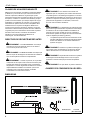
A (1)
[Extension column]
B (1)
[cable cover]
(2-CPAE300)
INSTALLATION
IMPORTANT ! : The following procedure assumes that
the UL Listed CPA ceiling plate (not included) has been
properly installed following instructions provided with
ceiling plate.
1.
5.
(CPAE-024 shown as example)
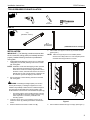
Place cable cover (B) onto column (A) at desired location.
(See Figure 1)
NOTE: Cable cover (B) may be cut into smaller pieces if
desired. Use a utility knife to cut cover and place pieces
at desired mounting locations on column.
Install CPAE Series Extension column into UL Listed CPA
ceiling plate (not included) following instructions included
with ceiling plate.
6
NOTE: Installation of hex head self-tapping screws (included
with Listed Chief accessories and mounts) will be
easier when screws are carefully aligned with holes in
extension column, and a drill and nut driver is used. If a
drill will NOT be used, a small amount of pressure will
be needed to get the self-tapping screws started.
2.
5
Secure extension column following instructions included
with ceiling plate.
5
WARNING: Exceeding the weight capacity can result in
6
serious personal injury or damage to equipment! It is the
installer’s responsibility to make sure the combined weight of
all components located within the mounting system of the
CPAE Extension Columns does not exceed 500 lbs (226.8 kg).
•
3.
4.
The weight capacity of the CPAE Extension Columns
may be LIMITED to the lowest weight capacity of any
other component or accessory used within the
mounting system.
Install and secure mount (not included) to lower end of
extension column (A) following instructions included with
mount.
Remove adhesive from back of cable cover (B).
Figure 1
6.
Route cables as desired through cover (B). (See Figure 1)
3